1
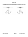
RotorSport UK Ltd Aircraft serial no. RSUK/CAVP/ Aircraft 25hr Service Worksheet Aircraft registration no. Worksheet date: Tsk Repetition or comments Actions taken & comment Eng’r Licenced Task Description No. initial Eng’r Purpose of this worksheet: To be applied for the first 25hr (+/-5hrs) service of a Cavalon Pro Gyroplane with Woodcomp KW-31 variable pitch propeller. If prior to renewal of the aircraft’s Certificate of Validity, the owner is also referred to the renewal requirement list on the RSUK website. Refer to Maintenance Manual RSUK0335. Some of the checks and serviceability are ‘on condition’, meaning the Engineer has the responsibility to decide if an item is acceptable for service. Some of the work involved affects CRITICAL PARTS and/or CRITICAL ASSEMBLIES (as identified below) – when working on these items follow only the procedures described in the Maintenance Manual RSUK0335. NOTE! Cowls and covers must be removed to undertake this service. Refer to Cavalon Pro Pilots Handbook RSUK0334 for guidance. The task numbers listed in the left-most column are rationalised i.e. identical on all Cavalon Pro Service Worksheets. The task numbers may not therefore be sequential Preparatory work 1 3 4 5 6 7 Review the aircraft documents (and the list of publications towards the end of this Worksheet) to determine any outstanding, specific or additional requirements to be conducted. Clean the aircraft, remove any dirt, dust, loose items. During cleaning inspect for any fluid leaks. Perform an external visual inspection of all cowlings and mast covers. Record any cosmetic damage on the graphic at the end of this document then remove the items. Perform a detailed inspection (no cracks, distortion, missing parts). Remove keel-tube cover, leaving loose on tube Remove all service covers (external), inspection hatches (internal) and the removable firewall panel. Perform a detailed inspection (no cracks, distortion, missing parts). Lift stick gaitor(s) away from the Velcro retention to cockpit floor Copyright RotorSport UK Ltd Consult RSUK to organise any repairs or replacements required Consult RSUK to organise any repairs or replacements required Page 1 of 17 Form F192 Rev2 dated 17.03.15 RotorSport UK Ltd Airframe Inspection 10 11 13 14 15 16 20 Check - Bolt torques – mast fittings Inspect – mast rubber bushings for failure or free play, shown by any sign of wear or damage between the upper mast (stainlesssteel) and lower mast (part of body) Inspect – upper mast for damage, twisting, buckling or other deformation, or cracks, especially at welded joints. Inspect – Condition of keel-tube and security of attachment to composite body (Screws and band-clamp) Check tail-plane horizontal (i.e. keel-tube not twisted) Inspect – keel-tube protection pads (condition and attachment). Inspect - External structure of body sound with no cracks, distortion or damage. Pay particular attention to the lower mast area around the air-intake duct. Undercarriage – main gear and brakes Inspect - landing gear spar and attachments to body for damage or fatigue (cracks & deformation). Copyright RotorSport UK Ltd Torque-check the M8 countersunk screws to 22Nm (2 pairs). If any visible movement remove screw, re-Loctite 243 and replace tightening to 25Nm +/3Nm. Second signature required if any screw removed/replaced. st 1 inspection Name: Engineer authorisation no: Sig:………………………………. nd Instrument S/No:………………………. 2 inspection Name: Engineer authorisation no: Or, qualified pilot licence no: Calibrated until:………………………… Sig:……………………………… If cracks or deformation found then ground aircraft and call RSUK for advice. If cracks or deformation found then ground aircraft and call RSUK for advice. If cracks or deformation found then ground aircraft and call RSUK for advice. CRITICAL PARTS & ASSEMBLY CRITICAL PARTS & ASSEMBLY Replace if worn – see Cavalon Pro AMM RSUK0335 If cracks or deformation found then ground aircraft and call RSUK for advice. If cracks or deformation found then ground aircraft and call RSUK for advice. Page 2 of 17 Form F192 Rev2 dated 17.03.15 RotorSport UK Ltd 21 22 Inspect – wheel spats general condition, security of mounting and tyre clearance. Inspect – main wheels general condition, correct pressure, condition of tread, correct seating of valve and cap, secure installation, free movement but no play in wheel bearings, presence and condition of creep-mark on tyre/rim No fabric to show through the tread area. Recommended 0.5mm min tread No cracks in side-walls Tyre pressure 1.8 to 2.2 bar (latter if heavily loaded). Increase to 2.3bar if operating at 560kg MTOW Tyres OK and pressures recorded as: Main LH…………….. Main RH…………….. Instrument S/No:………………………. Calibrated until:………………………… 23 25 40 41 42 43 50 51 52 Inspect – wheel brakes for secure installation and correct operation, no fluid leaks from caliper. Condition of pads and brake disc. Inspect – brake lines for secure installation, no leaks or chafing Undercarriage – nose-wheel Inspect – wheel spat for general condition, security of mounting and tyre clearance Inspect - nose-wheel general condition, correct pressure, condition of tread, correct seating of valve and cap, secure installation, free movement but no play in wheel bearings. Inspect - nose-wheel fork for general condition, secure installation, freedom of movement, no excessive play, distortion or damage Inspect - nose-wheel rubber damper general condition and correct operation External lights Op/C check red anti-collision light function and security(fitted to each mainwheel spat) Op/C check strobe function Op/C check nav light function Copyright RotorSport UK Ltd No fabric to show through the tread area. Recommended 0.5mm min tread No cracks in side-walls Tyre pressure 2.0 to 2.4bar (latter if heavily loaded) Tyre OK and pressure recorded as: Nose…………………. Red to left, green to right, white to rear Page 3 of 17 Form F192 Rev2 dated 17.03.15 RotorSport UK Ltd 53 54 Op/C check nose light function Op/C check landing light function and security (fitted in binnacle under nose) Electrical/instruments 60 Inspect – panel mounting screws secure 61 Inspect - panel connections for security 62 F/C – slip indicator 65 Inspect – gel battery for security of mounting, casing leakage and state of charge Op/C check function of instrument panel lights Op/C check function of cabin light (if fitted) 66 67 Confirm slip-string undamaged and free-moving If required connect ground-power to fully charge battery in anticipation of tests later in this Worksheet Rotor head 83 Inspect - brake pad for function. Pad replaceable as a service item 84 Op/C - Check roll and pitch trim cylinders for free function and slider damage or excess seal leakage. Check all attachment hardware secure and verify 4-off split pins in place and correctly formed: (Main bearing bolt, teeter bolt, pitch bolt, roll bolt) Seal service kit is available from RSUK 85 Second signature required if any pin replaced CRITICAL PARTS & ASSEMBLY st 1 inspection Name: A3-7 authorisation no: Sig:………………………………. nd 2 inspection Name: Engineer authorisation no: Or, qualified pilot licence no: Sig:……………………………… Copyright RotorSport UK Ltd Page 4 of 17 Form F192 Rev2 dated 17.03.15 RotorSport UK Ltd Rotor Head Controls 100 101 102 104 105 106 107 110 111 112 113 114 115 116 F/C - rod ends for cracks & freedom of movement both free and at control extremes F/C- rotor head reaches pitch and roll stops Inspect – pitch and roll angles achieved Inspect – pitch and roll cable attachments to upper mast secure Inspect (inside a/c) - all bearings free, all bearing retaining rivets secure, Pushrods, attachments and pivot mountings secure with no damage or chafing. Electrical cables and connectors undamaged. Service/lube – lubricate bearings and ball joints with Ballistol oil Inspect – push/pull cable mountings secure with no chafing. Op/C - for free play in stick control eg bearings or cable wear Nose-wheel and Rudder controls Op/C – Check pedals for ease of movement Inspect – tension of cable between central control link (mixer unit) and nose-wheel link and re-tension if required. Check turnbuckles secured and no chafing of cables. Service/lube - lubricate pedal bearing and sliding block of adjuster with Ballistol oil Inspect - visible rudder cables for frays, corrosion, wear or chafing, and any crimped fittings for signs of movement. Lubricate cables with Ballistol oil. Inspect – all clevis joints at central control link (mixer unit) secured, free to move and no chafing. Inspect – central control link (mixer unit) freedom of movement and main bolt secured. Inspect – security of wire-locking retaining the rudder cables to the keel-tube. Copyright RotorSport UK Ltd CRITICAL PARTS & ASSEMBLY Check from each seat See Cavalon AMM RSUK0335. Access main bolt through rubber plug located centrally underneath body Page 5 of 17 Form F192 Rev2 dated 17.03.15 RotorSport UK Ltd 117 118 Inspect - tail rod-end bearings for looseness and freedom of operation and fitted with snubbing washers. Lubricate control cables with Ballistol oil Inspect – security and integrity of keel tube in area of attachment to body 119 Inspect – integrity of tail attachment lugs welded to keel-tube (4-plcs) 120 Inspect - tail for security to airframe (4-bolts). Use 10x magnifying glass and suitable illumination to check for cracks in the tube Use 10x magnifying glass and suitable illumination to check for cracks on outside of the joint. Torque-check the M8 bolts to 12Nm (4-plcs). If any visible movement remove each bolt, re-Loctite 243 and replace, tightening to 15Nm Second inspection required if any bolt removed/replaced. Instrument S/No:………………………. Calibrated until:………………………… 121 Inspect – rudder to tail fastenings. Inspect tail and rudder for signs of composite damage and cleanliness of drain holes. Torque-check the single M6 or M8 bolt at the top bearing. If any visible movement remove bolt, re-Loctite 243 and replace,: M6 test at 8Nm, fit to 10Nm M8 test at 10Nm, fit to 12Nm Second inspection required if bolt removed/replaced. Instrument S/No:………………………. CRITICAL PARTS & ASSEMBLY CRITICAL PARTS & ASSEMBLY st 1 inspection Name: Engineer authorisation no: Sig:…………………………………. nd 2 inspection Name: Engineer authorisation no: Or, qualified pilot licence no: Sig:………………………………….. st 1 inspection Name: Engineer authorisation no: Sig:………………………………….. nd 2 inspection Name: Engineer authorisation no: Or, qualified pilot licence no: Sig:………………………………….. Calibrated until:………………………… Copyright RotorSport UK Ltd Page 6 of 17 Form F192 Rev2 dated 17.03.15 RotorSport UK Ltd 122 F/C rudder control cable tension (pedal load check) For limits and methods see Cavalon AMM RSUK0335 Instrument S/No:………………………. Reading…………………….. Calibrated until:………………………… 123 Inspect – rudder control angles For limits and methods see Cavalon AMM RSUK0335 Instrument S/No:………………………. Reading……………………… Calibrated until:………………………… 124 130 133 135 136 Overall check that all control system bolts are correct items, properly fitted and tight Engine NOTE! All engine checks to be in accordance with manufacturers manual! Engine service fasteners For engine servicing refer to the engine manual issued with the aircraft (Rotax 914F). The full annual engine service is required only when no engine servicing has been carried out in the last 12 months. Otherwise apply ‘on condition’. Servicing must be carried out in line with, and recorded on, the Rotax service schedule contained within the ‘Line Maintenance’ manual for the engine fitted. A record of any work carried-out must be made in the Engine Log Book. If the magnetic inspection plug or the crankshaft locking screw plug are disturbed then any wire-locking present must be properly reinstated Engine, other Service/lube - Ensure choke and throttles move freely from stop to stop, and that turbo detent can be felt correctly. Ensure cables are synchronised. Inspect engine bearer bolts for paint stripe, and if moved, re loctite and tighten to 35Nm. Otherwise check bolt torque. Reapply paint stripe as required. Instrument S/No:………………………. Calibrated until:………………………… Inspect - oil cooler general condition, security of mountings, no leaks or cracks in fittings. Copyright RotorSport UK Ltd Page 7 of 17 Form F192 Rev2 dated 17.03.15 RotorSport UK Ltd 137 138 139 140 141 142 143 144 145 150 151 154 156 Inspect – all oil hoses and pipes for secure installation, no leaks, chafing, hardening of pipes or abrupt direction changes. Check condition of heat-insulating tubes under engine. Inspect – oil thermostat assembly for secure attachment, no cracks or leaks from fittings. Inspect – all coolant hoses for condition and secure installation, no leaks, chafing or porosity. Inspect – condition of heat protection on coolant hose from Cylinder #2. Inspect - coolant radiator for secure installation, cleanliness, leaks or damage Inspect – radiator fan for correct operation, no damage to cage or blades Inspect – coolant overflow tank for correct coolant level, secure installation, no chafing Inspect – exhaust system for general condition, secure installation, no leaks, cracks or loose rivets. Check security of turbocharger installation Inspect – after-muffler clamps for deterioration and secure fitment and that wire-locking in place (2-plcs) Fuel system Inspect – security of fuel tanks and fuel cross-over tube/clamps. No evidence of leakage in fuel tank compartment. Inspect – operation and sealing of fuel-drain valve Inspect – fuel cap for condition, tightness, correct function and cleanliness of vent hole. Inspect - in area protected by removable firewall and in engine compartment check all fuel lines for condition, secure installation, presence of fire-protective sleeve, no chafing or kinks. Copyright RotorSport UK Ltd Fan runs in direction of ram-airflow with engine running. Use dipstick for coolant level. See Cavalon POH RSUK0334 Use tap-test to inspect for cracks Note that rubber strips are not fitted to Cavalon Pro Page 8 of 17 Form F192 Rev2 dated 17.03.15 RotorSport UK Ltd 157 158 159 170 171 174 176 177 178 Inspect – security and function of electric fuel pumps Op/C – correct operation and security of fuel shut-off valve, correct operation of safety-guard Op/C – functionality of fuel gauge Pre rotator Inspect – security of gearbox and pneumatic pipe to pre-rotator clutch. Inspect- drive shafts for bend or damage. No bearing play or cracks in flanges of u/j couplings Inspect – bendix to ring-gear engagement. Adjust if necessary Service/lube – clean then apply a minimal smear of light oil or WD40 to ring gear teeth Service/lube – sliding shaft coupling with grease and verify free movement Service/lube –uppermost drive shaft protected with Waxoyl Copyright RotorSport UK Ltd Function determined by sound on operation ie that the reading is consistent with that shown on the tank dip-stick See Cavalon AMM RSUK0335 NB: Do not lubricate the bendix mechanism Castrol LM or equivalent Apply with brush, do not spray. Page 9 of 17 Form F192 Rev2 dated 17.03.15 RotorSport UK Ltd Trim System, Rotor Brake & Pneumatics 183 Op/C – Full functional check, pneumatic system – refer as required to the maintenance manual for fault finding and rectification, and a more comprehensive understanding of the test background. REPEAT TEST FOR LEFT STICK (IF FITTED TO AIRCRAFT) Woodcomp KW-31 Propeller NOTE! All propeller checks to be in accordance with manufacturers manual! 190 Check – propeller blades for cracks, delamination or impact damage. 191 Check – security of propeller protection tape Check – satisfactory condition/function of the tab washers between mounting bolts and gearbox flange (6-plcs). 192 Copyright RotorSport UK Ltd In the ‘Brake’ position, engage brake, Max pressure obtained: confirm operation, and that function is acceptable. Pressurise to maximum. Change to flight – check for 8 sec max to release air from brake system. In ‘Flight’ position check that trim goes on and off in same direction as button. In ‘Flight’ position move stick fully forward. Depress pre rotator button. Ensure the rotor head cylinder engages, and pump runs – and when the stick is pulled back the pump stops. Return the stick to the front, release pre rotator and confirm that pressure is applied to trim and stick comes back slightly. Press right roll and ensure stick then moves right and bar indicator does the same. Repeat to left, then centralise indicator – and check for stick return to mid position. In ‘Brake’ position, put 3 bar pressure on and ensure pre rotator does not function Press the ‘Interlock release button’ and ensure that pre rotator functions (movement of head cylinder) with brake engaged. For propeller servicing refer to the Woodcomp User Manual UM-05 EN issued with the aircraft. Servicing must be carried out in line with the Woodcomp service schedule contained within the propeller manual. A record of any work carried-out must be made in the Propeller Log Book. Minor damage may be repaired as defined in Woodcomp User Manual Section 19 May be replaced as defined in Woodcomp User Manual Section 19 If replacement is required first tighten the bolts (progressively) to 22Nm before setting the tab locking. Page 10 of 17 Form F192 Rev2 dated 17.03.15 RotorSport UK Ltd 193 Check – security of brush box fasteners and condition of brushes Minimum engagement of brush in housing 4mm, (Original length 14mm) Instrument S/No:………………………. Calibrated until:………………………… 197 201 205 Adjust the propeller to the fully coarse pitch position, visually verifying that all blades move correctly and simultaneously and that the controller LED2 (Max) warning light functions correctly Return the propeller to the fully fine position, verifying correct function of the LED1 (Min) warning light. Rotor Cavalon Pro gyroplanes have a variant of RotorSystemII in which the blades have reduced angle of incidence (RotorSystem II 8.4m RAO). Identification is by red end-caps and black clamping profile. Inspect blades to manufacturers recommendations for any damage, splits etc. Confirm teeter bolt nut is hand tight (1-2Nm max) and split-pin fitted and correctly formed. These rotor blades are lifed at 2,500hrs. The rotor must not be replaced with a different type. Repair only as Cavalon AMM RSUK0335 CRITICAL PARTS & ASSEMBLY Dupilicate signature required if disturbed CRITICAL PARTS & ASSEMBLY st 1 inspection Name: Engineer authorisation no: Sig:………………………………….. nd 2 inspection Name: Engineer authorisation no: Or, qualified pilot licence no: Sig:………………………………….. Copyright RotorSport UK Ltd Page 11 of 17 Form F192 Rev2 dated 17.03.15 RotorSport UK Ltd 206 Check – torques on blade to hub bar bolts/nuts in situ If any evidence of blade to hub looseness it will be necessary to remove the rotor, dis-assemble blades from hub bar and check holes for wear or fretting. On re-assembly M8 Bolt torque is 25Nm. Refer to Section 9 “General Notes” of the Maintenance Manual for re-usage of nyloc nuts CRITICAL PARTS & ASSEMBLY Instrument S/No:………………………. Calibrated until:………………………… Body and doors 210 211 212 213 214 215 Inspect – doors for cracks, damage or distortion preventing easy opening and closing Inspect – door hinges for security, cracks or fractures Inspect – plexiglass surfaces (3-plcs) for cleanliness and obscurity. Determine if acceptable for flight F/C – opening and closing operation, and effectiveness of door locks F/C – free and correct operation of sliding side windows (DV windows) F/C – security and free movement of rotary window vents See Cavalon Pro AMM RSUK0335 for load values Pitot-static system 220 221 Inspect – pitot tube general condition, secure installation, no obstructions. . Check correct function of heater (Caution: risk of burn injury) Inspect – static ports open, placards installed, no obstructions Other Copyright RotorSport UK Ltd Page 12 of 17 Form F192 Rev2 dated 17.03.15 RotorSport UK Ltd 225 226 227 228 229 230 231 232 233 234 Inspect – Cabin ventilation – ensure port under body is free from obstruction F/C – Cabin heat (if fitted) – ensure watervalve opens and closes on cockpit demand and that electric fan starts on selection of “hot”. Inspect – seat mountings secure and backrest adjustment correct operation Inspect – all seat belt attachment points for tightness and security Inspect – headset connector plate in good condition and headset hanger secure Inspect - external radio antenna, check for damage and security. Inspect – external transponder antenna, check for damage and security Inspect; bearing temp indicator and OAT indicators for clear display Check Fire-warning LED flashes three times on power-up then off Overall check that all cockpit and panel fittings are secure Final ground run checks prior to release 250 Re-install the removeable firewall panel 251 Re-install keel-tube cover 252 Check all service pipes and cables around engine are secured Op/C – full functional check of engine start and run up to normal operating temperature Op/C- - with propeller set to fully fine ensure engine achieves at least 5,400rpm on one fuel pump only, and with both pumps running. OP/C - complete mag drop checks at 4,000rpm 253 254 255 Fitted centrally on the underbody Fitted to the rhs of the underbody. Follow safe practice, aircraft tied-down and with qualified operator or pilot only. Propeller may be damaged if in fully coarse pitch during this test RPM achieved:………………….. See Cavalon POH RSUK0334 for limits Mag drop L:…………………….. Mag drop R:…………………….. Copyright RotorSport UK Ltd Page 13 of 17 Form F192 Rev2 dated 17.03.15 RotorSport UK Ltd 256 257 259 260 Confirm-‘Gen’ light is on when engine not running, and off (or flickering gently) when running at above 2000rpm. Confirm-‘Gen2’ light is on when engine not running, and off (or flickering gently) when running at above 2000rpm. Inspect – instruments for measurements consistent with ambient conditions Observing Rotax shut-down requirements stop engine. Inspect - Power plant and coolant system for leaks Finalization work 270 Carry-out a tool and loose article check 271 Inside the a/c refit the stick gaitor(s). Verify full-and-free stick movement Re-install all inspection hatches (internal) and all service covers (external) Re-install all cowlings and mast cover 272 273 274 If external generator fitted Ensure all log book entries completed appropriately List of documents for Task 1 (Preparatory work) Confirm Service bulletins incorporated (from RSUK website, full list available with applicability) Confirm Airworthiness Directives incorporated (from CAA website, CAP747 and 661) CAP 747 Document date or issue checked, plus notes: CAP 661 Document date or issue checked, plus notes: EASA AD check (EASA website): note date checked and any actions required Copyright RotorSport UK Ltd Page 14 of 17 Form F192 Rev2 dated 17.03.15 RotorSport UK Ltd Confirm compliance to the Type Certificate Data Sheet (TCDS) for the Cavalon Pro. Note any non-compliances and actions taken. Tasks completed by (name): Engine hours logged: Signature: Initial: Airframe hours logged: Date: (to compare to check sheet) Aircraft hour-meter reading: The technical content of this document is approved under the authority of the UK CAA Design Organisation Approval Ref: DAI/9917/06 Certificate of Release to Service: The work recorded above (all pages) has been completed to my satisfaction and in that respect the aircraft is considered fit for flight. Comments: Name: Signature: Date Initial: (to compare to check sheet CAA Authorisation Ref No: Note to Engineer; remember to reference this worksheet and RSUK0335 within the logbooks, together with your CAA authorisation code. Work undertaken may be noted on this worksheet, or if required on another sheet (such as F093) also referenced in the logbook. Modifications undertaken must be noted with their MC approval no. Check the back pages to complete these too for modifications, service bulletins, ADs, etc. Copyright RotorSport UK Ltd Page 15 of 17 Form F192 Rev2 dated 17.03.15 RotorSport UK Ltd Any cosmetic damage noted on first inspecting the aircraft should be marked on this graphic and brought to the owner’s attention Copyright RotorSport UK Ltd Page 16 of 17 Form F192 Rev2 dated 17.03.15 RotorSport UK Ltd Appendix Requirements for certifying signatures/initials on this worksheet With the exception of “Permitted Pilot Maintenance” (see the relevant RSUK Aircraft Maintenance Manual and CAA publication CAP 733), all maintenance work on RSUK gyroplanes must be certified by a CAA Authorised Person (a Licenced Engineer). Case 1: for work not involving engine controls, or flying controls, or vital structural points The person(s) performing the work should complete the worksheet columns as below: If the person completing “Eng’r” does not have Licenced Engineer authorisation there must be a second initial by a CAA authorised person in each adjacent “Licenced Engineer” cell, denoting acceptance of the task specified. If the person has Engineer authorisation the “Eng’r” cell should be struck out and a single entry of initials made in the Licenced Eng’r certifier cell Case 2: for work where engine controls, or flying controls, or vital structural points are disturbed, where a duplicate inspection is required (and shown in the worksheet). The person(s) performing the work should complete the worksheet columns as shown above and repeated below: If the person completing “Eng’r” does not have Licenced Engineer authorisation there must be a second initial by an CAA authorised person in each adjacent “Licenced Eng’r” cell, denoting acceptance of the task specified. If the person has Licenced Engineer authorisation the “Eng’r” cell should be struck out and a single entry of initials made in the Licenced Eng’r cell In addition to the above there is a requirement for inspection, then duplicate inspection (by an independent person) of the finished task: st The licenced engineer certifying the task must enter his name, CAA authorisation number, and full signature under “1 inspection”. nd The independent second person must enter his name, CAA authorisation number or Pilots Licence number, and full signature under “2 inspection”. This second person must be suitably qualified and may be: another licenced or CAA authorised engineer a qualified gyroplane pilot. In this case the pilot must append his Pilot’s Licence number to his signature. It is the second signatory’s responsibility to ensure he/she understands the task and what it is they are inspecting and signing for. Verification of Initials, Signature and Authorisation The person performing the work must complete the “Tasks completed by” statement towards the end of the worksheet. The licenced engineer must complete and sign the “Maintenance Release” on the last page of the Worksheet. Copyright RotorSport UK Ltd Page 17 of 17 Form F192 Rev2 dated 17.03.15