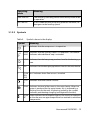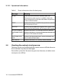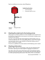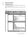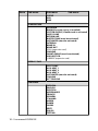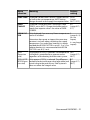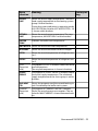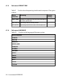
1
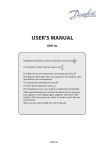
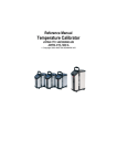
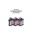
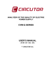
User manual
DHP-S&DP
VUIFM102
If these instructions are not followed during
installation and service, Danfoss A/Sliability
according to the applicable warranty is not
binding. Danfoss A/S retains the right to
make changes to components and specifications without prior notice.
© 2010 Copyright Danfoss A/S.
The Swedish language is used for the original
instructions. Other languages are a translation of original instructions.
(Directive 2006/42/EG)
Contents
1
2
Important information......................................................................................................................... 3
1.1
Safety precautions................................................................................................................................... 4
1.2
Protection.................................................................................................................................................... 5
About your heat pump........................................................................................................................ 6
2.1
3
Product description................................................................................................................................. 6
2.2
The principles of the heat pump........................................................................................................ 6
2.3
Hot water tank (option).......................................................................................................................... 8
2.4
Room sensor (option)............................................................................................................................. 8
Operating instructions......................................................................................................................... 9
3.1
Control panel............................................................................................................................................. 9
3.2
Checking the coolant circuit pressure............................................................................................ 14
3.3
Checking the water level in the heating system........................................................................ 15
3.4
Checking safety valves......................................................................................................................... 15
3.5
In the event of leakage......................................................................................................................... 16
4
Menu information............................................................................................................................... 17
5
Troubleshooting.................................................................................................................................. 25
6
Terms and abbreviations.................................................................................................................. 26
7
References............................................................................................................................................. 28
4.1
5.1
INFORMATION menu............................................................................................................................ 17
Alarm.......................................................................................................................................................... 25
VUIFM102 – 1
1
Important information
Note! If the installation is not used during the winter, the heating
system must be drained of water, otherwise there is a risk of frost
damage to the installation.
The system can be considered maintenance free but certain checks are
necessary.
Before changing the control computer’s settings, first find out what these
changes mean.
Contact your installer for any service work.
Caution! This apparatus is not intended for persons (including
children) with reduced physical, sensory or psychological
capacity, or who do not have knowledge or experience, unless
supervised or they have received instructions on how the
apparatus functions from a safety qualified person.
Note! Children are not permitted to play with the apparatus.
User manual VUIFM102 – 3
1.1
Safety precautions
1.1.1
Installation and maintenance
DANGER! Only authorized installers may install, operate and
carry out maintenance and repair work on the heat pump.
DANGER! Only authorized electricians may modify the electrical
installation.
DANGER! DANGER TO LIFE! Only authorized refrigeration
technicians may work on the refrigerant circuit.
1.1.2
System modifications
Only authorized installers may carry out modifications on the following
components:
•
•
•
The heat pump unit
The pipes for the refrigerant, brine, water and power
The safety valve
Do not carry out construction installations that may affect the operational
safety of the heat pump.
1.1.3
Safety valve
The following safety precautions apply to the hot water circuit’s safety
valve with corresponding overflow pipe:
•
•
Never block the connection to the safety valve’s overflow pipe.
Water expands when it is heated, this means that a small amount of
water is released from the system via the overflow pipe. The water
that exits the overflow pipe can be hot! Therefore, allow it to flow to
a floor drain where there is no risk of burning yourself.
4 – User manual VUIFM102
1.2
Protection
1.2.1
Corrosion Protection
Due to the risk of corrosion, avoid using different types of sprays in the
vicinity of the heat pump. This particularly applies to:
•
•
•
•
Solvents
Chlorinated cleaning agents
Paints
Adhesives
User manual VUIFM102 – 5
2
About your heat pump
2.1
Product description
The heat pump is a heating system for heating and hot water if an external
water heater is installed (accessory). It has a compressor developed solely
for heat pumps.
The heat pump is equipped with control equipment which is presented
in a graphical display. The control equipment is also prepared for monitoring via the internet.
Heat enters the house via a water borne heating system. The heat pump
supplies as much of the heat demand as possible before auxiliary heating
is engaged and assists. Additional heater is an accessory.
The heat pump heating system consists of two basic units:
•
•
Heat pump unit
•
•
Scroll compressor
Control equipment
The heat pump unit consists of the following components:
Stainless steel heat exchanger: condenser, evaporator and de-superheater
•
Circulation pumps for collector- and heating system
The control equipment controls the components included in the heating
installation (compressor, circulation pumps and exchange valve) and
determines when to start and stop the pump as well as producing heat
for the house or hot water. If the additional heat (accessory) is installed
the additional heating is controlled by the control equipment. The control
equipment unit consists of the following components:
•
•
•
2.2
Control computer, as well as operator’s panel with graphical display
Temperature sensors (outdoor, supply line, return line and hot water)
Room sensor (option)
The principles of the heat pump
A heat pump utilises the energy found in a natural heat source. Simply
put, it obtains energy in the form of heat from a heat source.
6 – User manual VUIFM102
The heat pump is, therefore, a very environmentally friendly and economical way of heating a house.
5
4
8
3
6
7
2
1
Figure 1.
The principles of the heat pump
The heat pump has four separate fluid circuits
•
Brine circuit (1) – is a fluid (brine) filled hose lowered into a lake, buried
in the ground or lowered into bedrock. The brine obtains energy from
the surroundings by the fluid temperature in the hose being heated
a few degrees.
•
Refrigerant circuit (7) – is a circuit in the heat pump that through
evaporation, compression and condensation takes energy from the
brine circuit and supplies it to the heat transfer fluid circuit. The refrigerant is chlorine free.
User manual VUIFM102 – 7
•
Heat transfer fluid circuit (8) – is the water that transports the heat/
energy to the heating system and the hot water tank.
•
Hot gas circuit – is a high temperature circuit for the hot water circuit’s
final heater. If the heat pump is not connected to any water heaters,
the hot gas circuit does not need to be connected.
The brine circuit (1) evaporates the refrigerant in the evaporator
(2), using heat from lake, ground or rock. The refrigerant is turned
to gas.
The refrigerant passes the compressor (3) where the pressure and
temperature are raised.
The refrigerant then continues to the de-superheater (4). Here a
small high temperature output is used, for example, to top up the
hot water temperature.
The heat transfer fluid circuit (hot gas circuit) condenses refrigerant
to liquid form in the condensor (5), by giving off heat to the house
and hot water.
The refrigerant then passes through the expansion valve (6) where
the pressure and temperature drop and converts the refrigerant
from liquid to liquid and gas. The process then starts again.
1.
2.
3.
4.
5.
2.3
Hot water tank (option)
The heat pump can also produce hot water for an external water heater.
The water temperature of the hot water tank is controlled by the control
switch and cannot be adjusted.
Hot water production stops when the control switch reaches its maximum
operating pressure.
2.4
Room sensor (option)
The heat pump system can be equipped with a room sensor as an option.
Only authorised electricians may carry out the installation.
See wiring diagram for connections.
8 – User manual VUIFM102
3
Operating instructions
3.1
Control panel
3.1.1
Function description
The heat pump has an integrated control system which automatically calculates the heat demand in the house to ensure that the correct amount
of heat is produced and emitted where necessary. There are many different values (parameters), which are required in order to do the calculation
of the heat demand.
During installation and service, the control panel is used to set and change
values that have to be adapted according to the house demand. The control panel is integrated into the front of the heat pump and consists of a
display, a keypad and an indicator. In the display, a simple menu system
is used to navigate the desired settings and values. During operation, the
User manual VUIFM102 – 9
display always shows the set ROOM value, the operating mode and the
status of the heat pump.
ROOM
20°C
NO HEAT DEMAND
1
OPERAT. AUTO
2
3
Figure 2.
Position
Display, keypad and indicator.
(20°C)
Description
1
The display text and symbols are only shown as examples. Certain
symbols cannot be displayed at the same time.
2
Keypad:
+ Plus sign used to scroll up a menu or increase the values.
- Minus sign used to scroll down a menu or reduce the values.
> Right arrow used to select a value or open a menu.
< Left arrow to cancel selection or exit a menu.
3
Indicator
The control system is operated via a user-friendly menu system, which is
shown in the display. Use the keypad’s four navigation symbols to navigate the menus and increase or reduce the set values.
The INFORMATION menu is opened by pressing the left or right buttons.
The INFORMATION menu has a number of sub menus, see Menyinformation.
10 – User manual VUIFM102
For installation and service, the SERVICE menu is used, which is opened
by pressing the left button for five seconds. The SERVICE menu has a
number of sub menus, see Menu information.
The INFORMATION and SERVICE menus are intended for two categories
of user, customers and installers. Customers may only open the INFORMATION menu with a limited number of settings. Installers have to be able
to change many settings in the control settings. The SERVICE menu is
therefore hidden from the customers.
1
2
Figure 3.
The menus are reached by pressing different buttons.
Position
Description
1
Information menu
Press the left or right buttons.
2
Service menu
Press and hold the left button for at least five seconds
The indicator at the bottom of the control panel has three modes:
•
•
Not lit, means that the heat pump is not powered.
•
Flashing, means an active alarm
When the light shines continuously, the heat pump has power and is
ready to produce heat or hot water.
Caution! During a service that consists of replacing the display
card, all heat pump settings are reset to factory settings.
Therefore note current settings before replacement.
User manual VUIFM102 – 11
3.1.2
Display
The display shows information about the heat pump’s operation, status
and any alarms, in text form. Operating mode and status, indicated by
symbols, are also shown in the lower part which shows the heat pump’s
active processes.
Note! To change the display language, press the following
sequence of buttons: right arrow, arrow down to bottom menu,
arrow right, scroll between languages using + or -. Then select
language using right arrow.
3.1.2.1 Operating modes
Table 1.
Shows the set operating mode of the heat pump.
Operating
mode
(OFF)
Meaning
The installation is fully switched off. This mode is also used
to acknowledge certain alarms.
Caution! If the operating mode OFF is to be
used for long periods during the winter, the
water in the heating system in the heating
system must be drained, otherwise there is a
risk of frost damage.
AUTO
The heat pump and the auxiliary heater are automatically
controlled by the control system.
HEAT PUMP
The control system is controlled so that only the heat pump
unit (compressor) is allowed to operate. In this operating
mode peak heating charging (anti-legionella function) of
the hot water will not run because the auxiliary heater is not
used.
12 – User manual VUIFM102
Operating
mode
Meaning
AUX. HEATER
The control system only permits the auxiliary heater to be
in operation.
HOT WATER
In this mode the heat pump only produces hot water, no
heat goes to the heating system.
3.1.2.2 Symbols
Table 2.
Symbols shown in the display.
Symbol
HP
1
Meaning
Indicates that the compressor is in operation.
LIGHT Indicates that the auxiliary heater is in operation. The number
NING indicates what additional step is activated.
HOUS Indicates that the heat pump produces heat for the heating sysE
tem.
TAP
F
Indicates that the heat pump produces heat for the water heater.
FLOW An F indicates that a flow sensor is installed.
SENSOR
CLOC
K
Indicates that tariff control is active.
TANK
Indicates the level of hot water in the water heater. When hot
water is produced for the water heater, this is indicated by a
flashing icon for the tank. A lightning symbol by the symbol
indicates peak heating charging (anti-legionella function).
SQUA Either indicates that the operating pressure switch has deployed,
RE
or that the pressure pipe temperature has reached its maximum
temperature.
User manual VUIFM102 – 13
3.1.2.3 Operational information
Table 3.
Shows information about the heat pump.
Message
Meaning
ROOM
Shows the set ROOM value. Standard value: 20°C.
If the accessory room sensor is installed it shows the
actual temperature and the desired indoor temperature
is shown within brackets.
START
Indicates that there is a need for heat production and that
the heat pump will start.
EVU STOP
Indicates that the additional function EVU is active. This
means that the heat pump is off as long as EVU is active.
NO HEAT DEMAND
Indicates that there is no heating production demand.
HEAT PUMP START -- Indicates that there is a heating production demand and
XX
will start in XX number of minutes.
3.2
HEAT PUMP+AUX.
HEAT
Indicates that heat production is active with both compressor and auxiliary heater.
AUX. HEATER
Indicates that there is an auxiliary heater demand.
Checking the coolant circuit pressure
The brine circuit must be filled with the correct amount of fluid otherwise
the installation may become damaged.
Ensure that system has the necessary pressure, however, not above maximum pressure of 6 bar.
14 – User manual VUIFM102
See the installation instructions when filling brine.
Symbol explanation
1
Used when filling
2
Connected to brine circuit
1
2
Figure 4.
system
3.3
Filling the brine
Checking the water level in the heating system
The line pressure of the installation must be checked once a month. Ensure
that heating system has the necessary pressure, however, not above maximum pressure of 6 bar.
You can use normal tap water when topping up the heating system. In
certain exceptional cases the water quality may be so poor (for example
very hard water) that it is not suitable for filling the heating system. If
unsure, contact your installer.
Do not use any additives for water treatment in the heating system’s water!
3.4
Checking safety valves
Both the safety valves for the heating system must be checked at least
four times a year to prevent lime deposits clogging the mechanism.
The safety valve of the water tank protects the enclosed heater against
over pressure in the water tank. It is mounted on the cold water inlet line,
its outlet opening facing downwards. If the safety valve is not checked
User manual VUIFM102 – 15
regularly, the water tank might be damaged. It is quite normal that the
safety valve lets out small amounts of water when the water tank is being
charged, especially if a lot of hot water was used previously.
Both safety valves can be checked by turning the cap a quarter of a turn
clockwise until the valve lets out some water through the overflow pipe.
If a safety valve does not work properly, it must be replaced. Contact your
installer.
The opening pressure of the safety valves is not adjustable.
3.5
In the event of leakage
In the event of leakage in the hot water pipes between the unit and water
taps, close the shut-off valve on the cold water inlet immediately. Contact
your installer, see References, Page 28.
In the event of leakage in the brine circuit, turn off the heat pump and call
your installer immediately, see References, Page 28.
16 – User manual VUIFM102
4
Menu information
4.1
INFORMATION menu
Open the menu by pressing the left or right button. The menu also shows
history and operating times.
Menus in italics are only visible if the expansion card (accessory) is installed.
Table 4. Used to change the heat pump's operating modes and to adjust
the heat curve.
Menu
Sub menu
Sub menu
Sub menu
Ø
CANCEL
Ø
INFORMATION
OPERAT.
AUTO
HEAT PUMP
AUX. HEATER (must
be activated)
HOT WATER (must be
activated)
MANUAL TEST
HEAT CURVE
CURVE
MIN
MAX
CURVE 5
CURVE 0
CURVE -5
HEAT STOP
REDUCTION
TANK TEMP (if buffer tank is activated)
OVERCHARGE (if buffer tank is activated)
ROOM FACTOR (if a room sensor is installed)
POOL (expansion card)
POOL HYSTERESIS (expansion card)
HEAT CURVE 2 (if shunt group is activated)
User manual VUIFM102 – 17
Menu
Sub menu
Sub menu
Sub menu
CURVE
MIN
MAX
TEMPERATURE
OUTDOOR
ROOM (if a room sensor is installed)
SYSTEM SUPPLY (if buffer tank is activated)
SUPPLY LINE
RETURN LINE
BUFFER TANK (must be activated)
HOT WATER (must be activated)
INTEGRAL
BRINE IN
BRINE OUT
POOL (expansion card)
COOLING
SHUNT GROUP (must be activated)
2ND HEAT CIR.
CURRENT (expansion card)
OPERAT. TIME
HEAT PUMP
AUX. HEAT 1
AUX. HEAT 2
AUX. HEAT 3
HOT WATER (must be activated)
COOLING
ACT COOLING
LANGUAGE
SVENSKA
ENGLISH
DEUTSCH
NEDERLANDS
FRANÇIS
ESPAÑOL
ITALIANO
NORSK
DANSK
SUOMI
EESTI
POLSKI
ČEŠTINA
18 – User manual VUIFM102
4.1.1
Sub-menu OPERAT.
Table 5.
Menu
selection
(OFF)
Used to select operating mode.
Meaning
Factory
setting
The installation is fully switched off. This mode is
also used to acknowledge certain alarms.
-
CANCEL = starting point, no changes made.
To select OFF as operating mode, press the minus
sign once to scroll down one step and press the
right arrow once.
AUTO
Automatic operation with both heat pump and
auxiliary heater permitted. If the number of power
stages for auxiliary heating are set to zero (SERVICE
-> AUX. HEATER -> MAX STEP) only AUTO or OFF
can be selected as operating mode.
HEAT PUMP Operation with only heat pump permitted.
-
Note! No peak heating charging
(anti-legionella function) with only
heat pump operation.
AUX.
HEATER
Operation with only auxiliary heater permitted.
-
HOT WATER Operation with heat pump for hot water produc- tion and auxiliary heater during peak heating
charging (anti-legionella function).
MANUAL
TEST
Only displayed when the value for MANUAL TEST is set to 2 in
The SERVICE menu. Outputs that control components are activated manually.
User manual VUIFM102– 19
4.1.2
Sub-menu HEAT CURVE
Table 6.
Used to change settings for the heat curve.
Menu
selection
Meaning
CURVE
Calculated supply temperature at 0°C outdoor
40°C
temperature. Shown as a graphic curve. The curve (for under
will be limited by the set values of MIN and MAX. floor heating
30°C)
(range:
22°C / 56°C)
MIN
Minimum permitted supply temperature, if the
temperature for heat stop has been reached and
the heat pump has stopped.
MAX
Maximum calculated setpoint value of the supply 55°C
temperature.
(for under
floor heating
45°C)
(range:
40°C / 85°C)
CURVE 5
Local increase or reduction of CURVE at an outdoor 0°C
temperature of +5°C. Shown in the graph for
(range: -5°C /
CURVE.
5°C)
CURVE 0
Local increase or reduction of CURVE at an outdoor 0°C
temperature of 0°C. Shown in the graph for CURVE. (range: -5°C /
5°C)
CURVE -5
Local increase or reduction of CURVE at an outdoor 0°C (range:
temperature of -5°C. Shown in the graph for
-5°C / 5°C)
CURVE.
HEAT STOP
Maximum outdoor temperature when heat production is permitted.
If the heat stop has been activated the outdoor
temperature must drop 3°C below this setting
before the heat pump resumes the heating cycle.
Factory
setting
10°C
(range:
10°C / 50°C)
17°C
(range: 0°C /
40°C)
REDUCTION Only appears if the tariff control function has been 2°C
activated. Lowering set room temperature. Active (range: 1°C /
when a 10 kΩ connection is placed across the EVU 10°C)
input connections.
20 – User manual VUIFM102
Menu
selection
Meaning
Factory
setting
TANK TEMP Displayed if buffer tank is active. Charges the buf- AUTO
fer tank to the set temperature. AUTO setting
(range:
charges the tank to the supply line setpoint value. 30°C / 55°C)
OVERCHARGE
Displayed if the buffer tank is active and TANK
TEMP is set to AUTO. Charges the buffer tank to
supply line setpoint value + the value of OVERCHARGE.
0°C
(range: 0°C /
5°C)
ROOM FAC- Only displayed if an accessory Room temperature 2
sensor is installed.
(range: 0 / 4)
TOR
(0 = no
Determines how great an impact the room tem- impact,
perature is to have when calculating the supply
4 = very large
temperature. For under floor heating it is recom- impact)
mended that ROOM FACTOR is set to 1, 2 or 3. For
radiator heating it is recommended that ROOM
FACTOR is set to 2, 3 or 4.
POOL
(Expansion
card)
Only appears if POOL is selected. The temperature 20°C
in the pool is controlled by a separate sensor
(range: 5°C /
regardless of the heating and hot water system. 40°C)
POOL HYSTE- Only appears if POOL is selected. The difference 0°C
RESIS (Expan- between the desired charge value (adjustable) and (range: 5°C /
sion card)
actual value to the pool sensor. Pool hysteresis
40°C)
does not affect the integral value.
User manual VUIFM102 – 21
4.1.3
Sub menu HEAT CURVE 2
Only appears if shunt group sensor is connected and activated in menu
SERVICE -> INSTALLATION -> SYSTEM -> SHUNT GROUP.
Table 7.
4.1.4
Used to change settings for heat curve 2.
Menu
selection
Meaning
Factory
setting
CURVE 2
Calculated shunt group temperature at 0°C out- 40°C
door temperature. Shown as a graphic curve. The (range:
curve will be limited by the set values of MIN and 22°C / 56°C)
MAX.
MIN
Minimum permitted shunt group temperature, if 10°C
the temperature for heat stop has not been
(range:
reached.
10°C / 50°C)
MAX
Maximum permitted shunt group temperature.
55°C
(range:
15°C / 70°C)
Sub-menu TEMPERATURE
The history of different temperature measurements can be viewed by
pressing the right arrow key. The graph shows the last 60 measurement
points for the set time interval (SERVICE -> INSTALLATION -> LOG TIME).
In the event of an alarm, history stops being logged until the alarm is reset
by changing the operating mode to OFF.
Table 8. Used to indicate the prevailing temperatures, history and set/calculated values.
Menu
selection
Meaning
Factory setting
OUTD
Shows the actual outdoor temperature.
-
ROOM
Shows the actual set temperature.
-
SYSTEM
SUPPLY
Displays system supply temperature at the buffer tank system.
22 – User manual VUIFM102
Menu
selection
Meaning
Factory setting
SUPPLY
LINE
Shows the actual supply temperature. The calcu- lated supply temperature to the heating system
group is within brackets.
During hot water production in operating mode
AUX. HEATER the value for HOT WATER STOP + 10°
is shown within brackets.
RETURN
LINE
Shows the actual return temperature. The stop
temperature, MAX RETURN is within brackets.
-
BUFFER
TANK
Indicates the buffer tank temperature.
-
HOT WATER Shows the actual hot water temperature.
-
INTEGRAL
Shows the actual calculated value for integral.
-
REFR 1
Shows the actual temperature of refrigerant sen- sor 1.
REFR 2
Shows the actual temperature of refrigerant sen- sor 2.
POOL
(Expansion
card)
Only appears if POOL is selected. Shows the actual pool temperature.
The set pool temperature is shown in brackets.
SHUNT
GROUP
Only appears if SHUNT GROUP is selected. Shows the actual supply temperature. The calculated
supply temperature to the shunt group is within
brackets.
2ND HEAT
CIR.
Shows the temperature of the second heating circuit if installed by the buffer tank system.
CURRENT
(Expansion
card)
Only appears if CURRENT LIMITER is selected.
Shows the actual current consumption. The set
value for MAX CURRENT is shown between brackets.
User manual VUIFM102 – 23
4.1.5
Sub-menu OPERAT.TIME
Table 9.
in hours.
Used to show the operating time for each component. Time given
Menu
selection
Meaning
Factory
setting
HEAT PUMP Compressor operating time for both heating and hot water production.
4.1.6
AUX. HEATER Operating time of auxiliary heater.
-
HOT WATER
-
Operating time for hot water with compressor.
Sub-menu LANGUAGE
Table 10. Used to set the language of the menu system.
Menu selection
SVENSKA
ENGLISH
DEUTSCH
NEDERLANDS
FRANÇAIS
ESPAÑOL
ITALIANO
NORSK
DANSK
SUOMI
EESTI
POLSKI
ČEŠTINA
24 – User manual VUIFM102
5
Troubleshooting
5.1
Alarm
In event of alarm this is indicated in the display with the text ALARM and
an alarm message, see following table. For alarms that are not reset automatically acknowledgement is required. Acknowledge the alarm by setting the heat pump to operating mode OFF.
Message
Meaning
HIGH PRESSURE
ERROR
Tripped high pressure switch. Compressor stopped.
LOW PRESSURE
ERROR
Tripped low pressure switch. Compressor stopped.
MOTOR P ERROR
Deployed overload relay (Overcurrent relay compressor),
or deployed overload relay for outdoor unit fan. Compressor stopped.
OUTDOOR SENSOR
Fault in outside sensor. When the control system calculates the heat demand, zero degrees is used.
SUPPLY LINE SENSOR
Supply line sensor error. Everything stops except the
heating system’s circulation pump.
RETURN LINE SENSOR
Return sensor fault. Return temperature = Supply line – 5
is used. Calculated supply temperature limited to maximum 45°C.
HOT WATER SENSOR Fault on sensor for start temperature. No hot water production.
ERR PHASE SEQ.
Alarm that indicates that there is an incorrect phase
sequence to the compressor. Only display and only the
first 10 minutes.
HIGH RETURN
Alarm that indicates that high return temperature prevents the compressor’s operation.
BRINEFLOW LOW
The flow sensor produces an alarm when the ambient
temperature of the brine circuit becomes too low.
In event of alarm the heat pump will if possible supply heating to the
house, primarily with the compressor, secondarily with the additional
heater. Hot water will stop to indicate that something noteworthy has
occurred.
User manual VUIFM102 – 25
6
Terms and abbreviations
Table 11.
Terms and abbreviations
Term
Explanation
Evaporator
In the evaporator, energy is retreived from the heat source
and the refrigerant passing through the evaporator turns
to gas.
De-superheater
In the de-superheater part of the total heating output is
released (approx. 15%). A higher temperature than the
normal condensation temperature can found here.
Integral
INTEGRAL is the heating system’s energy balance. Heat
generation is controlled by a calculated requirement. This
value is determined by comparing the actual supply temperature with its calculated supply temperature. The difference between the temperatures is added over time.
The resulting value is referred to as the integral. The integral is calculated automatically. The value of the integral
can be viewed in the display under the sub-menu TEMPERATURE.
Compressor
The compressor raises the temperature and pressure of
the refrigerant.
Condenser
In the condenser, the refrigerant supplies its heat energy
to the heat transfer fluid circuit.
Curve
The CURVE value is set via the display. The set value is the
calculated set point value of the flow line at outdoor temperature of 0°C.
Brine
Is a water based mixture that transports energy from the
heat source to the heat pump.
Brine circuit
The fluid circuit transports energy from the heat source to
the heat pump.
Refrigerant circuit
Is the circuit in the heat pump that through evaporation,
compression and condensation takes energy from the
brine circuit and supplies it to the heat transfer fluid circuit.
Refrigerant
Is the fluid that transports heat from the brine circuit and
supplies it to the heat transfer fluid circuit.
Radiator
Heater element, element.
26 – User manual VUIFM102
Term
Explanation
Control computer
The control computer controls the entire heating installation. All settings are stored and the history of the installation is registered here. The control computer’s settings
can be changed via the display.
Room
If ROOM shows 20°C the heat curve is unaffected. If ROOM
shows higher or lower, this indicates that the heat curve
has been adjusted up or down to change the indoor temperature.
Heat transfer fluid
circuit
The heat transfer fluid circuit obtains heat/energy from
the refrigerant circuit, which it then transports to the
water tank or heating system.
Heat curve
The control computer determines the correct temperature of the water to be distributed to the heating system
based on the heat curve. The indoor temperature is adjusted by changing the gradient of the heating system’s
CURVE.
User manual VUIFM102 – 27
7
References
Piping installation
Date
........................................................
Company
........................................................
Name
........................................................
Tel. No.
........................................................
Electrical Installation
Date
........................................................
Company
........................................................
Name
........................................................
Tel. No.
........................................................
System adjustment
Date
........................................................
Company
........................................................
Name
........................................................
28 – User manual VUIFM102
System adjustment
Tel. No.
........................................................
User manual VUIFM102 – 29
VUIFM102