1
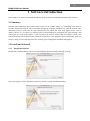
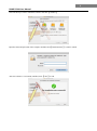
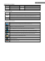
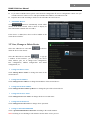
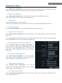
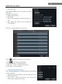
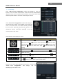
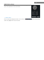
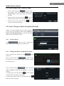
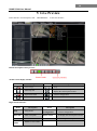
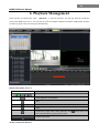
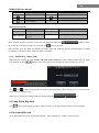
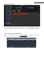
NVMS-1200 User Manual Contents 1 2 3 4 5 6 7 8 9 Software Introduction ........................................................................................................................................ 1 1.1 Summary ................................................................................................................................................ 1 1.2 Install and Uninstall ............................................................................................................................... 1 1.2.1 Install the Software .................................................................................................................... 1 Login Software .................................................................................................................................................. 3 2.1 Login ...................................................................................................................................................... 3 2.2 Control Panel Instruction ....................................................................................................................... 3 Device Management .......................................................................................................................................... 5 3.1 Add Device ............................................................................................................................................ 5 3.2 View, Change or Delete Device ............................................................................................................. 6 3.3 Area and Camera Management.............................................................................................................. 8 3.3.1 Area Management ...................................................................................................................... 8 3.3.2 Camera Management ................................................................................................................. 9 Group and Scheme Setting .............................................................................................................................. 14 4.1 Create, Change or Delete the Camera Group....................................................................................... 14 4.2 Add or Remove the Camera Group ..................................................................................................... 15 4.3 Create, Change or Delete Group Dwell Scheme ................................................................................. 15 4.3.1 Create Scheme ......................................................................................................................... 15 4.3.2 Change and Delete Group Dwell Scheme................................................................................ 15 Live Preview .................................................................................................................................................... 16 5.1 Preview ................................................................................................................................................ 17 5.1.1 Monitory Point Preview ........................................................................................................... 17 5.1.2 Stop Preview ............................................................................................................................ 17 5.2 Dwell Preview ..................................................................................................................................... 17 5.2.1 Group Dwell Preview .............................................................................................................. 17 5.2.2 Scheme Dwell Preview ............................................................................................................ 18 5.3 Preview Control ................................................................................................................................... 19 5.4 Snap ..................................................................................................................................................... 19 5.4.1 Snap ......................................................................................................................................... 19 5.4.2 Snap Number ........................................................................................................................... 20 5.4.3 Snap Path ................................................................................................................................. 20 5.5 Multi-screen to Preview ....................................................................................................................... 20 5.6 Talk and Broadcast............................................................................................................................... 20 5.6.1 Talk .......................................................................................................................................... 20 5.6.2 Broadcast ................................................................................................................................. 21 5.7 PTZ Control ......................................................................................................................................... 21 5.7.1 Parameter Configuration of PTZ ............................................................................................. 21 5.7.2 PTZ control .............................................................................................................................. 21 Playback Management ..................................................................................................................................... 22 6.1 Snap When Playback ........................................................................................................................... 23 6.2 Download Record ................................................................................................................................ 23 6.3 View the Progress of Downloading ..................................................................................................... 24 Alarm Management ......................................................................................................................................... 25 7.1 Sensor Alarm ....................................................................................................................................... 25 7.2 Motion Detection Alarm ...................................................................................................................... 26 7.3 Video Loss Alarm ................................................................................................................................ 26 7.4 Alarm Preview ..................................................................................................................................... 26 7.4.1 Alarm Preview Configuration .................................................................................................. 26 7.4.2 Alarm Preview ......................................................................................................................... 27 Local Log ......................................................................................................................................................... 28 8.1 Search log ............................................................................................................................................ 28 8.2 Log Maintenance ................................................................................................................................. 28 8.3 Export .................................................................................................................................................. 28 User Management ............................................................................................................................................ 29 9.1 Create a Resource with the Default Permission ................................................................................... 29 9.2 Create, Change and Delete Users ........................................................................................................ 29 9.3 Account Right Configuration............................................................................................................... 30 10 Basic ................................................................................................................................................................ 32 10.1 Location and Path ................................................................................................................................ 32 10.2 Backup and Restore ............................................................................................................................. 32 10.2.1 Backup System Configuration data ......................................................................................... 32 10.2.2 Restore System Configuration Data......................................................................................... 32 10.3 Manually Trigger the Alarm Output .................................................................................................... 33 1 NVMS-1200 User Manual 1 Software Introduction In this chapter, you will read a detailed introduction of the operation environment and install of this software. 1.1 Summary Network Video Monitoring System (hereinafter referred to as “NVMS-1200”) is a monitoring client which is specially designed for network video surveillance through the computer with MAC OS. After the network video monitoring system is well built, the super administrator can control the video input signal devices, such as cameras, domes, etc., to achieve live monitor, video record and backup by configuring the video parameters and viewing the live in the control panel. Users can choose the menu to control video surveillance system in the control panel. The main functions of the control panel include live view, playback, device management, group and scheme settings, user account and permission, local log, basic configuration and alarm management. 1.2 Install and Uninstall 1.2.1 Install the Software Double click “NVMS1200.pkg” file to enter the Installation Wizard. Click【Continue】to install. Choose the path you want to install the software by clicking “Change installation location” 2 NVMS-1200 User Manual Select the disk you want to install the software and click【Continue】. Input the name and password of the computer and then click【Install Software】 button to install. After the software is successfully installed, click【Close】to end. 3 NVMS-1200 User Manual 2 Login Software 2.1 Login First time to login: ① For the first time to run the NVMS-1200, you need to register a super administrator. You shall self-define the username and password. ② To avoid forgetting the password, you can set some questions to help you find the password quickly. ③ After you input your user name, password and set the questions and answers, click【Register】to enter into the software. Input the username and password you have created and then click【Login】to enter the control panel of the software. 2.2 Control Panel Instruction The control panel of NVMS-1200 is shown below. There are five areas in the main interface of this software. The descriptions of each area are as follows: 4 NVMS-1200 User Manual Area Description Area Description 1 Function Area 2 Tab Bar—to display the operated functions 3 Menu Bar 4 Alarm Information List. 5 Status information list Description of Menu Bar Menu Description Start Export the control panel, live preview, playback tab and lock or exit the client. View Export the live preview, control panel, local log, alarm preview, playback, user account and permission, basic configuration and device management and organize the live view System Help Including lock client,broadcast to device, switch user, import or export configuration, etc. View user manual and software version Descriptions of Function Module Menu Description Live Preview: To view live images and record, snap, control PTZ, etc. Playback: To remotely play the local record. Device Management: To create, modify or delete areas, devices and cameras. Group and Scheme Settings: To create, modify or delete camera groups and schemes. User Account and Permission: To add, modify, delete user and user permission. Local Log: To search, view and backup local log. Basic Configuration: To setup record partition and path, system startup and maintenance & backup and restoration. Alarm Management: To add or remove the sensor of the area; To setup alarm trigger and modify the area of the sensor. 5 NVMS-1200 User Manual 3 Device Management In the control panel, click icon to enter the device management interface. 3.1 Add Device Click button to enter the interface. ① Select device type and input device name; ② Input IP address or domain, port of the device and then enter its user name and password. ③ Create an area. If you haven’t created area, you can click “Create a New Area” to create. ④ Check “Upload bandwidth more than 2M” according to the actual network situation. Checking or not checking it will affect the stream choice of live preview. Note: You can click “Create an Area” shortcut menu under Device to create an area in the control panel. You can also check “Auto report” to add device. The setting steps are as follows: Choose the device type and check “Auto”. Input device name. If you want to add DVR, please enter NetworkSever tab from device. Check “Enable”, input IP address 6 NVMS-1200 User Manual and port (2009) of NVMS-1200 & device ID. If you want to add IP camera, please enter Network Configuration Server Configuration. Check “Do you want IP camera to connect server” and input NVMS-1200 Address, Port and Device ID. Input the Device ID according to the device ID of DVR or IP camera device. Add Online Devices Click button to automatically search online devices in the local network. Click a device to display its basic information. Double click it to add it. If the device is added, this device will be hidden in the search device interface. 3.2 View, Change or Delete Device Select the added device and click delete the device from the list. button to Select the added device and click to pop up a window. In this interface, you can change the device name, address, port, etc, or change basic configuration, time configuration, DDNS configuration and Email configuration, etc. Change the Device Name Click “Change Device Name” to change the name of the selected device. Change Device Address Click “Change Device Address” to change the IP address of the selected device. Change Device Port Number Click “Change the Port Number of Device” to change the port of the selected device. Change Device User Name Click “Change Device User Name” to change the device account name. Change Device Password Click “Change Device Password” to change device password. Change Connection Bandwidth Check “Upload bandwidth more than 2M” according to the actual situation. Note: Checking or not checking it will affect the stream choice of live preview. 7 NVMS-1200 User Manual Change Basic Configuration Click “Change Basic Configuration” to pop up a dialog box. You can change the basic configuration of device and check “Permission Check” or “Record Coverage” according to the actual situation. Change Time Configuration Click “Change Time Configuration” to enter the interface. Change the time and date if you need. Check “Sync by NTP Server” to synchronize with NTP server. View Device Log Click “View Device Log” to enter the interface. Choose the type of system logs; enter start time and enter time to search the log information of the device. View Disk Information Click “View Disk Information” to check the detail information of disk from the list. Change Network Configuration Click “Change Network Configuration” to enter the interface. You can change HTTP port, Server port; network address, etc. Note: If changing the port and IP address there, the network will disconnect. Then you need to accordingly change the port and IP address of the device connecting the NVMS-1200. Alarm Input Trigger and Schedule Configuration Click “Alarm Input Trigger and Schedule Configuration” to enter the interface. Select a sensor corresponding to the alarm input; choose a type and holding time for it. You also can set trigger alarm or other configurations. Please refer to the picture on the right. Device Alarm Output Configuration Click “Alarm Output Configuration” to enter the interface. Select an alarm output and holding time; then edit a name for it. You can enable buzzer alarm and set a time for it. Abnormal Alarm Configuration Click “Abnormal Alarm Configuration” in to enter the interface. Choose the alarm type according to your need. Enable “Buzzer Alarm” and select alarm out. User Information Management Click “User Information Management” shortcut to enter the interface. You can check the information of user who is logging in the device. 8 NVMS-1200 User Manual Email Configuration Click “Email Configuration” to enter the interface. You can configure the basic parameters of Email. DDNS Configuration Click “DDNS Configuration” to enter. You can configure the basic parameters of DDNS. 3.3 Area and Camera Management In the control panel, click “Change Camera Settings” under Device to enter the interface. You can modify or delete the area and manage the cameras. Select a camera you want to setup as shown in the below figure. Different devices have different functions. Not all devices have the above-mentioned camera settings. Please set up the camera parameters according to the features of your devices. 3.3.1 Click Area Management button to create area. Select an area and click change its name. Select an area and click it. Select an area and click button to button to delete to pop up a window. 9 NVMS-1200 User Manual ① Check the camera on the left column and click button to add the camera to the area. ② Check the camera on the right column and click button to remove the camera from the area. Select a camera and click button to modify the area of this camera. 3.3.2 Camera Management The real-time image will be displayed after selecting a camera. You can setup the parameters of this camera. Image Settings Image settings include image video parameter, image quality and image display. Click “Image video parameters” to enter the interface. ① Adjust the brightness, contrast, saturation and chroma of the image. ② Clicking 【Restore Default】 button will restore the above parameters to factory default settings. Click “Image Quality” under Image Settings to enter the interface. Choose the device stream, resolution, quality, etc. according to practical situation. Click “Image Display” to enter the interface. ① Create the camera’s name and set up its display position on the OSD including the time stamp. ② Click【Copy to】button to apply the settings to the selected channel. 10 NVMS-1200 User Manual Record Settings Click “Record Settings” to enter the interface as shown on the right. Under the record of device ① Enable schedule Record. ② Set schedule. ③ Choose pre-recording time, duration and record save time. ④ Click 【Copy to】 button to save the settings to the selected channel. The picture of setting schedule record of system: Click icon and move the cursor to select the time. Click icon to delete the selected time. Clicking “Manually” to manually input time Click “All” / “reverse” to quickly select the time. Click “Empty” to clear all the time. Motion Detection Alarm Settings Click “Area and Sensitivity” under Motion Detection Alarm Setting to enter the interface. ① Drag slide bar to set the sensitivity value. The higher the value is, the more sensitive it is. ② Click “Erase”/ “Add”, then hold press “Ctrl” and left click mouse to delete /add the area you want. 11 NVMS-1200 User Manual ③ Click 【All】/【Reverse】/【Clear All】 button to select area or clear all the area quickly. Click “Set Motion Alarm” under Motion Detection Alarm Setting to enter the interface. Note: Please refer to the user manual of the device for device linkage configuration. Click “System Trigger” under Motion Detection Alarm Setting to enter the interface. Under the system linkage, check “Trigger to Play Audio File”. If the motion alarm of a certain channel is triggered, there will be given out a sound like “beep”. Click 【Trigger the Big Screen】 button to select channel. If the motion alarm of the selected channel is triggered, a big picture will pop up on the screen. Video Loss Alarm Settings Click “Video Loss” to enter the interface. The steps of configuring video loss are same with the device settings, please refer to the video loss chapter of device user manual. Video Loss of System Click “Video Loss of System” to set. You can check “Trigger to Play Audio File”. If the video loss alarm of a certain channel is triggered, there will be given out a sound like “beep”. Click 【Trigger the Big Screen】 button to select channel. If the video loss alarm of the selected channel is triggered, a big picture will pop up on the screen. 12 NVMS-1200 User Manual PTZ Settings Click “PTZ Protocol Configuration” under PTZ Settings to enter the interface. You can enable or disable PTZ. From the Protocol and Baud Rate drop-down menu, choose a protocol and a baud rate to associate with the PTZ, and then input the address of the PTZ connecting the software. Click “Preset Point Configuration” under PTZ Settings to enter the interface. Enable corresponding preset points and create a new name in the “New Name” field by selecting the preset point. Adjust the dome direction, speed, etc by clicking the buttons. Click【Save Position】to save the current position of the dome. The definitions of the buttons are below: Buttons Description means the dome rotate up; dome rotate up right; rotate left down; rotate left; rotating means the dome rotate up left; means the means the dome rotate down. means the dome means the dome rotate right down; means the dome means the dome rotate right; means the dome stop Drag the slider bar to adjust rotation speed of the dome Focus button. Click obtain short focus button to obtain long focus. Click Iris button. Click button to increase light of the dome. Click to decrease light of the dome Zoom button. Click click button to button button to zoom in the picture of this camera. button to zoom out the picture of this camera Return to Area and Camera Management interface, and then click “Cruise Line Configuration” PTZ Settings. You can add/change/preview/delete curies. 13 NVMS-1200 User Manual In the Area and Camera Management interface, click “PTZ Track Settings” to see the picture on the right hand. You can set the PTZ track. Remove camera In the Area and Camera Management interface, select a camera, click window, click【OK】button to remove the camera. button to pop up a dialog 14 NVMS-1200 User Manual 4 Group and Scheme Setting In the interface of control panel, click “Group and Scheme Setting” to enter the interface. Please refer to the below picture: 4.1 Create, Change or Delete the Camera Group In the above interface, click button to create a group. Select a group in the group list, click to delete it. button Select a group and click button to enter the interface as shown on the right. You can change the group name and dwell time interval in this interface. 15 NVMS-1200 User Manual 4.2 Add or Remove the Camera Group ① Select a group and click button to enter the interface. Then click “Add or Remove the Camera Group” to pop up the window as shown on the right. ② Check cameras on the left and click button to add the selected cameras to the group on the right. ③ Check cameras on the right, then click to remove them from the group. button 4.3 Create, Change or Delete Group Dwell Scheme Scheme is used for dwelling group by group. Therefore, at least one group should be created. Click “Change or Delete the Group Dwell Scheme” on the left side of the menu to enter the interface as below. 4.3.1 Create Scheme Click button to create a scheme. The added scheme will be displayed in the scheme list. 4.3.2 Change and Delete Group Dwell Scheme Select a scheme in the scheme list, click to delete it. button Select a scheme and click button to enter the interface. You can change the name of scheme and the dwell time interval. Select a scheme and click button. Then click “Add or Remove Group of the Scheme” to enter the interface. Check group on the left and click button to add the selected group to the scheme on the right. Check group under scheme on the right and click button to remove the group. 16 NVMS-1200 User Manual 5 Live Preview In the interface of control panel, click “Live Preview” to enter the interface: Buttons description of live preview: Toolbar on the display window: Icon Description Icon Description Close image Snap Start/stop talk PTZ control. Clicking the icon will display the control panel of PTZ. Open/close audio Camera configuration Fit to window Zoon in Right button functions: Menu Description Menu Description Snap Snap picture Camera Configuration Enter the interface of the area and Camera configuration Start talk Start or stop talk PTZ Control To display the control panel of PTZ Stream Choose stream to view. Close Preview Close single channel preview Enable Audio Enable or close audio 17 NVMS-1200 User Manual 5.1 Preview 5.1.1 Monitory Point Preview To start the live preview, drag the cameras from the list to the right display window or select a window and double-click the camera to display the live image. You can drag the image to any window at random. Note: Node expansion rule: After the first time for setting the device and area, you shall obey the following rule to view all tree nodes: when the tree node is more than 64 nodes, the system will unfold the upper node by default. For example: A (There is camera group AC under A; sub-area a under AC; camera group ac under sub-area a). If the nodes number is more than 64, A will be unfolded and AC will be displayed, but a will not be unfolded and ac will not be displayed. If the node number of A is less than 64, A will be folded and all nodes need to be unfolded manually. 5.1.2 Stop Preview Close Preview of Channel Place your mouse on the window to display the menu toolbar, then click channel. icon to close preview of this Close Preview by Right-clicking Choose “Close Preview” by right-clicking the display window to close preview of this channel. Close All Preview Click icon on the main menu toolbar to close all the windows. 5.2 Dwell Preview After setting up group or scheme (Please refer to chapter 4 for creating group), enter to the live preview interface and click button to display the group list or scheme list. The below sections will introduce how to realize group dwell and scheme dwell. 5.2.1 Group Dwell Preview Start Group Dwell In the interface of live preview, click under scheme to any window( window at the set time. shortcut on the left side to display the groups. Drag a group icon stands for group). The cameras of this group will play one by one on this 18 NVMS-1200 User Manual Stop Group Dwell Right click the display window to select “Close Preview” to close preview of this channel or click the main menu bar to close all windows for stopping dwell. 5.2.2 icon on Scheme Dwell Preview Start Scheme Dwell In the interface of live preview, click shortcut on the left side and then drag a scheme to the right window to dwell ( icon stands for scheme).The screen mode will be distributed automatically according to the number of camera under the group 19 NVMS-1200 User Manual Note:To achieve dwell between devices, the device should be as a unit when adding groups. Then add all the groups into one scheme to dwell. Stop Scheme Dwell Click icon to close all the windows for stopping scheme dwell. 5.3 Preview Control Single Channel in Full Screen Double click the selected window to view in full screen. Double click again to recover the window. Stream of Live Preview Right click on the display window to choose recording stream. The above stream is main stream (eg: D1 25fps) and the below is sub stream(eg: CIF 6fps). Modify Device Stream: Click button on the display window to enter the Area and Camera Management interface. Click “Image Quality” under Image Setting to modify device stream. Please refer to chapter 3.3.2 Image Settings for details. Audio Right click on the displaying window to choose “Enable Audio” or click icon to enable audio of this channel. Note: Only one audio can be enabled at the same time. If enabling another channel’s audio, the enabled audio will be closed automatically. Zoom In Click image. icon on the toolbar in the displaying window to zoom in the image; click 5.4 Snap 5.4.1 Snap click button on the toolbar of the selected channel or right click to choose “Snap” to capture the pictures. After snapping pictures, a message prompt box will pop up to remind you the pictures are captured successfully and where the pictures are stored . icon to recover the 20 NVMS-1200 User Manual Note: Capturing pictures can be realized only in live preview or playback. 5.4.2 Snap Number In the interface of control panel, click “Set Snap Default Number” under Basic to configure the number you want to capture every time . 5.4.3 Snap Path In the control panel , click “Basic” to enter the interface. Click “Path of snap file” to select a folder to save the captured pictures. 5.5 Multi-screen to Preview In the interface of live preview, click button to plus a tab of live preview. Drag any tab of live preview to pop up an independent live preview interface as below. Multi-screen to display can be realized by dragging the independent interface to other screen (graphics card should support multi-screen output at the same time). Clicking the button of the live preview interface to choose “Tab View” can embed this tab in main interface .。 Note:1. 20 live preview tabs can be added. 2. Live preview interface can be displayed on multiple screens. 5.6 Talk and Broadcast 5.6.1 Talk Click button on display window or right click to pop up a menu bar. Choose “Start Talk” to enable bidirectional audio. Note: Since NVMS-1200 only allow opening one device’s talk at the same time, the system will stop talk with the 21 NVMS-1200 User Manual current device for enabling new talk with another device which is launching talk. 5.6.2 Broadcast ① Click “System” on the menu bar of software at the upper right ; choose “Broadcast” to enter the interface. ② Click button to pop up a window; then check the devices you want to broadcast, click 【OK】button to save the setting. ③ Click button to stop broadcast. 5.7 PTZ Control 5.7.1 Parameter Configuration of PTZ Please confirm the parameter of PTZ has been configured correctly before operating PTZ. Click icon in display window or “Change Camera Setting” under “Device” to enter the interface. Click “PTZ Setting” to enable PTZ and setup protocol, baud rate and address of PTZ. Note: Here the protocol, baud rate and address of PTZ must be consistent with the PTZ decoder. 5.7.2 PTZ control Return to the live preview interface after configuring parameter of PTZ; select the channel and click PTZ. icon or right click to choose “PTZ Control” to open the control panel of Click the direction buttons to control its rotational direction; drag the slider to control its speed. Click and buttons to adjust focus, iris and zoom. Select a preset point and click preset point to operate it. to operate this preset point or double click the Click【Cruise】button to list the cruises. Select a cruise and click cruising. PTZ can also support track, auto scan, wiper and light function. button to cruise; click button to stop 22 NVMS-1200 User Manual 6 Playback Management In the interface of control panel, click “Playback” to enter the interface. You can play back the record files saved in the HDD of the device. You can play the record of multiple channels meanwhile. Additionally, all those records are played at the same time point automatically. Buttons Description of Area 2 Icon Description Screen mode. 1,4,9,16,25 channels are optional Close playback of all channels Play Pause Stop Playback by single frame. When playback, click then click this button to play frame by frame. Playback speed bar Toolbar on Playback Window: button firstly and 23 NVMS-1200 User Manual Icon Description Icon Description Close playback Snap Open/close audio Zoom in Fit to window Right button functions: Menu Description Snap picture Snap Close Channel Menu Enable Audio Description Enable or close audio Close single channel preview In the playback interface, select the screen, date and channel and then click button to search the record file. After the record files are searched, click button to playback. In the timeline, green bar stands for manual record data; yellow bar stands for motion record data; blue bar stands for schedule record data; red bar stands for sensor record data. 6.1.1 Playback by Setting Time Right click the color bar to select “Set the Play Time of the Channel X”, then a dialog window pops up. Input time manually or click button to select time. The system will play the video from the time you set. Note: and buttons on the timeline are used to expand and narrow down the time bar, so you can choose a more accurate playback time. What’s more, you may also change playback speed by dragging bar. 6.2 Snap When Playback Click button on the playing window to capture pictures. A message prompt will pop up after snapping. 6.3 Download Record Click “Backup Record” in the control panel interface. This will bring up a window as shown below: 24 NVMS-1200 User Manual Select record channel, start time and end time, checkmark event type and then click【Record Search】button to search record information. After the information is searched, a backup information window will pop up by clicking【Download】button. Click【Browse】button to choose save path. Then click【OK】button to download record. 6.4 View the Progress of Downloading When starting downloading, you can view the progress of downloading and stop downloading manually by putting the cursor on the lower right corner (under button). 25 NVMS-1200 User Manual 7 Alarm Management 7.1 Sensor Alarm In the control panel, click “Alarm Management” to enter the interface. Add or Remove Sensor of the Area In the interface of Alarm Management, choose an area, click interface. button to enter the ① Check the sensor under the area on the right and click button to move out the sensor . ② Check the sensor on the left and click to add sensor. button Rename or Change Area In the interface of Alarm Management, choose a sensor and click click button to change the area of sensor. button to change its name; 26 NVMS-1200 User Manual Alarm Trigger Setup In the interface of Alarm Management, choose a sensor and click “Set Alarm Trigger” button to enter the interface. If checking “Trigger Alarm Playback”, there will be a sound like “beep” on an alarm. Add Associated Preview Camera Click to pop up a window; check cameras and click【OK】 button to save the setting. When sensor alarm is triggered, the alarm preview and e-map preview will pop up automatically. Select the added camera, click “Remove Associated Preview Camera” to remove the camera. 7.2 Motion Detection Alarm In the control panel, click “Change Camera Settings” under Device. Select a camera and click “Area and Sensitivity” to enter the interface as right. You can adjust the detection sensitivity and setup the motion area. Click “Set the Motion Alarm” to enter the interface. Enable motion detection alarm and set the alarm trigger. Please refer to section 3.3.2 for details. 7.3 Video Loss Alarm In the control panel, click “Area & Camera Management” under Device. Click “Video Loss” to enter the interface. The steps of configuring video loss are same with the device settings, please refer to the video loss chapter of device user manual. Choose a camera and click “Video Loss of System” to enter the interface. Please refer to section 3.3.2 for details. 7.4 Alarm Preview The interface of alarm preview will automatically pop up if the relevant alarm page and alarm preview have been already configured. 7.4.1 Alarm Preview Configuration Motion Detection Alarm: In the control panel, click “Change Camera Settings” under Device to enter the 27 NVMS-1200 User Manual interface. Select a camera, and then click “System trigger” shortcut under Motion Detection Alarm Settings to appear a window; click 【Trigger the Big Screen】 button under system linkage to select channel. Video Loss Alarm: Click “Video Loss of System” to enter the interface; click 【Trigger the Big Screen】 button under System Linkage to select channel. Sensor Alarm: In the control panel, click “Alarm Management” to enter the interface. Click “Set the Alarm Trigger” button to add the associated preview cameras. In the control panel, click “ Change Alarm Preview Settings” under Live Preview to pop up the window ① Alarm preview will pop up automatically on an alarm if checking “Automatic Pop-up Alarm Page”. ② Choose the number of screen. 7.4.2 Alarm Preview After configuring the alarm, the alarm preview will automatically pop up if the alarm of selected channels is triggered. The default pop-up window of system is independent interface. 28 NVMS-1200 User Manual 8 Local Log In the interface of control panel, click “Local Log” to enter the interface. 8.1 Search log Choose main type, sub type , set the start time and end time and then click【Inquire】button to search the relevant log information. click【First page】 【Previous】 【Next】 【Last page】to view the information on different pages. 8.2 Log Maintenance In the log interface, click button to pop up a dialog window. You can save the information of log for a certain time in this interface. 8.3 Export In the log interface, click button and then choose a storage path to export the log information. 29 NVMS-1200 User Manual 9 User Management In the interface of control panel, click “User Management” to enter the interface. There is only one super user registered by you when logging in the system for the first time. You can add several users and set right for them through the function of “Set Account Right”. 9.1 Create a Resource with the Default Permission In the above interface, clicking “Create a Resource with the Default Permission” means that permission of new resources will be given to all the users if you are going to create new resources. 9.2 Create, Change and Delete Users In Create Account the interface of User Management, click to pop up a dialog window. Input account name and password. Choose account type and default right. You can bind account by e-mail or telephone and add description if you wish. Note: Two types of user: administrator and operator. administrator enjoys all the system permissions except account and permission management. Operator only enjoy the permissions of broadcast, searching and exporting log. If you have checked “Default Permission” under initial permission when creating new account, all the resource 30 NVMS-1200 User Manual permissions and system permissions will be added for the user. Change Account In the interface of User Management, select a user and click button to enter the interface. You can change account name, password, e-mail address, etc. Delete Account In the interface of user management, select a user and click button to delete it . 9.3 Account Right Configuration In the interface of User Management, select a user and then click In Camera Permission the interface of Camera Permission, click button to add resources and check camera permissions on the right. You can add different permissions for different users. Device Permission Click “Device Permission” to enter the interface. Select the right on the right hand you want to enjoy. to enter the interface. 31 NVMS-1200 User Manual System Permission Click “System Permission” to enter the interface, you can set the right of broadcast , searching log information and exporting it for the user you selected. Restore Default Permission In the interface of account right management, select a user and click permission of this user. to restore default Clear Permission In the interface of account right management, select a user and click permission. to clear this user’s 32 NVMS-1200 User Manual 10 Basic In the interface of control panel, click “Basic” to enter the interface. Here , you can set up the path of backup and snap file, as well as backup and restore. 10.1 Location and Path Path of backup file setup:Click the shortcut menu in the above interface to set the backup path. Path of snap file setup: Click the shortcut menu in the above interface to set the snap path. 10.2 Backup and Restore When upgrading the software to a new version, you should firstly export the data of the previous version and then import to the new version so that repeated addition and settings could be avoided. 10.2.1 Backup System Configuration data In the interface of Basic Configuration, click “Backup System Configuration Data” to export the configuration data. 10.2.2 Restore System Configuration Data In the interface of Basic Configuration, click “Restore System Configuration Data” to import the configuration data. 33 NVMS-1200 User Manual 10.3 Manually Trigger the Alarm Output In the control panel, click “Manual Alarm Output” under Basic Configuration to enter the interface. Check “Enable”; select a corresponding device and alarm output; then edit a name for it . Then an icon will appear at the right bottom of the software. Clicking this icon will trigger the alarm of selected device.