1
P3000 Slave Marquee
Message Display
Hardware User Manual
(Manual Part Number MAN-P3000-001)
WARNING!
Programmable control devices such as UTICOR’s P3000 Slave Marquee, must not be used as
stand-alone protection in any application. Unless proper safeguards are used, unwanted start-ups
could result in equipment damage or personal injury. The operator must be made aware of this
hazard and appropriate precautions must be taken.
In addition, consideration must be given to the use of an emergency stop function that is independent of the programmable controller.
The diagrams and examples in this user manual are included for illustrative purposes only. The
manufacturer cannot assume responsibility or liability for actual use based on the diagrams and
examples.
Trademarks
This publication may contain references to products produced and/or offered by other companies.
The product and company names may be trademarked and are the sole property of their respective
owners. UTICOR Technology, L. P. disclaims any proprietary interest in the marks and names of
others.
Manual P/N MAN-P3000-001
© Copyright 2002–2003, UTICOR Technology, L.P.
All Rights Reserved
No part of this manual shall be copied, reproduced, or transmitted in any way without the prior
written consent of UTICOR Technology, L.P. UTICOR Technology, L.P. retains the exclusive rights
to all information included in this document.
MANUFACTURED and MARKETED
by
UTICOR TECHNOLOGY, L. P.
4140 Utica Ridge Rd. • Bettendorf, IA 52722-1327
Phone: 1-563-359-7501 • Fax: 1-563-359-9094 • www.UTICOR.net
P3000 Slave Marquee
...................................................................... (inside front cover)
.................................................................................................... i
................................................................................................. iii
.................................................................................................. iii
SECTION 1. INTRODUCTION
Manual Organization
................................................................................................... 2
Manual Overview
................................................................................................... 3
Need HELP?
................................................................................................... 3
1.0
Introduction to the P3000 Slave Marquee ................................................................ 4
1.1
Physical Characteristics ........................................................................................... 4
1.2
Master Control
................................................................................................... 4
1.3
Computer Control ................................................................................................... 5
1.4
Messages
................................................................................................... 5
1.5
Conclusion
................................................................................................... 6
1.6
Specifications
................................................................................................... 7
SECTION 2. UNIT HARDWARE
2.0
Introduction
................................................................................................. 10
2.1
Slave Interfacing ................................................................................................. 10
2.1.1
Power Input Terminals ............................................................................. 10
2.1.2
RS-422A Serial/Repeater Port ................................................................ 10
2.1.3
RS-232C Port .......................................................................................... 13
2.2
Switch One and Switch Two — Unit Address ......................................................... 13
2.3
Switch Three — Character Height/Baud Rate/ASCII Mode ................................... 15
2.4
Changing from 115 VAC to 230 VAC Input Power • Changing the Fuse ............... 15
2.5
Conclusion
................................................................................................. 16
SECTION 3. PMD MASTER CONTROL
3.0
Introduction
................................................................................................. 18
3.1
Master Control Preparation .................................................................................... 18
3.2
What Happens During Master Control ................................................................... 18
3.3
Addressing Slaves ................................................................................................. 19
3.4
Mixing Displays
................................................................................................. 20
3.5
Features of the P3000 Slave Marquee .................................................................. 20
3.6
Slave Control by Computer Controlled Master ...................................................... 24
3.7
Conclusion
................................................................................................. 25
SECTION 4. COMPUTER CONTROL
4.0
Introduction
................................................................................................. 28
4.1
Computer Communication Preparation .................................................................. 28
4.2
Unit Address
................................................................................................. 29
4.2.1
Addressing Slaves ................................................................................... 29
4.2.2
Active/Non-Active Slave Units ................................................................. 30
4.3
General Message Format ....................................................................................... 31
4.4
Message Codes
................................................................................................. 31
4.5
Message Replies ................................................................................................. 32
MAN-P3000-001
Phone: 1-563-359-7501 • Fax: 1-563-359-9094 • www.uticor.net
i
Introduction
Warning/Caution
Table of Contents
LIST OF FIGURES
LIST OF TABLES
P3000 Slave Marquee
4.6
4.7
4.8
4.9
4.10
4.11
4.12
4.13
4.14
4.15
Code 00 — Standard Reply Format ....................................................................... 33
Code 13 — Set Time and Date .............................................................................. 34
Code 14 — Write Data Set Data ............................................................................ 35
Code 15 — Select Active Slave .............................................................................. 36
Code 17 — Slave Display Packet Message .......................................................... 37
Code 18 — Status/ID Message .............................................................................. 39
PMD Message Format ............................................................................................ 40
4.12.1 Message Example ................................................................................... 41
4.12.2 Control Byte 1 .......................................................................................... 42
4.12.3 Option Byte 2 ........................................................................................... 43
4.12.4 Scroll Options Byte .................................................................................. 44
4.12.5 Scroll Time Byte ....................................................................................... 45
Message Text
................................................................................................. 45
4.13.1 Blinking Characters ................................................................................. 45
4.13.2 Time and Date Characters ...................................................................... 45
4.13.3 Variable Data Characters ........................................................................ 46
4.13.4 P3000 Slave Embedded Codes .............................................................. 46
Computer Interface Samples .................................................................................. 47
4.14.1 Sample Display Slave Packet Message in Basic ....................................... 47
4.14.2 Sample Display Slave Packet Message in Quickbasic .............................. 48
Conclusion
................................................................................................. 48
SECTION 5. ASCII PROTOCOL
5.0
Introduction
................................................................................................. 50
5.1
Preparation of the Unit ............................................................................................ 50
5.2
Terminal Operation ................................................................................................. 52
5.3
Operating Commands ............................................................................................ 54
5.4
PMD ASCII Slave Configuration ............................................................................. 59
5.5
Sample Messages 60
APPENDIX A
Outline Dimensions
............................................................................................... A-2
Error Messages
............................................................................................... A-5
PMD Master Control Errors ............................................................................................... A-5
Computer Control Errors ............................................................................................... A-5
XOR Checksum
............................................................................................... A-6
International Character Sets
............................................................................................... A-7
APPENDIX B
Ethernet Interface
............................................................................................... B-1
INDEX
................................................................................................ I-1
ii
Phone: 1-563-359-7501 • Fax: 1-563-359-9094 • www.uticor.net
MAN-P3000-001
P3000 Slave Marquee
Fig. 2-1.
Back View of P3000 Marquee Slave Display with Access Plate Removed .......... 10
Fig. 2-2.
P3000 Control Board Components ........................................................................ 11
Fig. 2-3.
RS-422A Serial/Repeater Port Interfacing ............................................................. 12
Fig. 2-4.
RS-232 Interfacing13
Fig. 2-5.
Switch One, Two, and Three Definitions ................................................................ 14
Fig. 2-6.
P3000 Jumper Settings for 115/230 VAC Operation and Fuse Location .............. 16
Fig. 4-1.
Unit Address Byte Designation ............................................................................... 29
Fig. 4-2.
Message Format for Computer .............................................................................. 31
Fig. 4-3.
Message Example Byte Diagram ........................................................................... 41
Fig. 5-1.
P3000 Back View with Access Plate Removed — Switch 3, Position 4 ................ 60
Outline Dimensions 1W x 2H ............................................................................................... A-2
Outline Dimensions 1W x 4H
............................................................................................... A-2
Outline Dimensions 2W x 2H ............................................................................................... A-3
Outline Dimensions 2W x 4H
............................................................................................... A-3
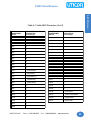
LIST OF TABLES
Table 2-1.
Table 2-2.
Table 4-1.
Table 4-2.
Table 4-3.
Table 4-4.
Table 4-5.
Table 4-6.
Table 4-7.
Table 4-8.
Table 4-9.
Table 4-10.
Table 4-11.
Table 4-12.
Table 4-13.
Table 4-14.
Table 5-1.
Table A-1.
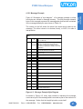
Switch One and Switch Two Definitions ................................................................. 14
Switch Three Definitions ......................................................................................... 15
Message Code Number Designations ................................................................... 32
Byte 6 - Active Unit Control Byte ............................................................................ 36
Bytes 6 through 9 - Definitions ............................................................................... 38
Message Format for PMDs ..................................................................................... 40
Message Options versus Message Formats .......................................................... 40
Bit Diagram of Control Byte 1 ................................................................................. 42
Bit Designations for Control Byte ........................................................................... 42
Bit Diagram of Control Byte 2 ................................................................................. 43
Bit Designations for Control Byte 2 ........................................................................ 43
Bit Diagram of Control Byte .................................................................................... 44
Bit Designations for Control Byte 3 ........................................................................ 44
Character Codes for Time and Date ...................................................................... 45
Character Codes for Variable Data ........................................................................ 46
P3000 Embedded Code Definitions ....................................................................... 46
Valid ASCII Characters ........................................................................................... 52
P3000 Part Numbers, Dimensions, and Configurations ...................................... A-4
MAN-P3000-001
Phone: 1-563-359-7501 • Fax: 1-563-359-9094 • www.uticor.net
iii
Introduction
LIST OF FIGURES
P3000 Slave Marquee
This page intentionally left blank.
iv
Phone: 1-563-359-7501 • Fax: 1-563-359-9094 • www.uticor.net
MAN-P3000-001
Introduction
In this chapter....
— Manual Organization
— Manual Overview
— Need HELP?
— Introduction to the P3000 Slave Marquee
— Specifications
1
P3000 Slave Marquee
Introduction
Manual Organization
The P3000 Slave Marquee Hardware User Manual is arranged in chapters. A description of key
information contained in each chapter is provided below.
Chapter
1
Introduction
This chapter introduces you to the manual organization and overview. Information
is provided on how to find help with installation of the hardware and programming.
Also provided is an introduction to the P3000 Slave Marquee, its physical characteristics, master control, computer control and messages. Specifications for the
various models of the P3000 are provided on page 7 of this chapter.
2
Unit Hardware
This chapter provides information on the P3000 Slave Marquee Hardware.
Included are sections on Slave Interfacing, DIP Switches, Changing Input Power
from 115VAC to 230VAC, and Changing the Fuse. Control board features and
settings are discussed, as well as accessing the board.
3
PMD Master Control
In this chapter, using a UTICOR PMD Master or Touch Panel to control the P3000
is discussed. Instructions on how to prepare the P3000 for Master Control and a
description of what happens during such control are provided. Slave Addressing
and unique features of the P3000 are discussed. You will find sections on the LED
Field, Frame Definitions, Character Height, Displaying Messages, Embedded
Codes for Computer Interface, and Slave Control by Computer Controlled Master.
4
5
A
2
Description
Computer Control
This chapter discusses how a computer can be used to control a P3000 slave. You
will be instructed on how to prepare the P3000 for computer control. Information is
provided on Unit Addressing and General Message Format. Detailed descriptions of
Message Codes and Message Replies, and how they work, are provided. At the
end of the chapter, Computer Interface Samples are provided.
ASCII Protocol
Chapter 5 defines ASCII Protocol and provides instructions on how to set up the
P3000 Slave to receive ASCII communication. A table of Valid ASCII Characters is
provided. There are sections discussing Blink Delimiters and Writing Characters to
the Display. Operating Commands and sample messages for an ASCII slave are
also provided.
Appendix A
The appendix includes outline dimension drawings, part numbers, and configuration for the 4 P3000 model types. Error Messages, XOR Checksum, and International Character Sets are also included in the appendix.
Phone: 1-563-359-7501 • Fax: 1-563-359-9094 • www.uticor.net
MAN-P3000-001
P3000 Slave Marquee
Manual Overview
PowerMarquee
User Manual
This manual, the P3000 Marquee Hardware User Manual, P/N MANP3000-001, and the PowerMarquee Programming Software User Manual,
P/N MAN-P3000-002 will take you through the steps necessary to get
your P3000 Marquee up and running in the shortest possible time. Although your familiarity with programmable message display devices will
determine how quickly you move through the steps — we’ve provided
you with easy, step-by-step instructions.
Need HELP?
PowerMarquee Programming Software Onscreen HELP
If you are using PowerMarquee Programming Software, context sensitive
onscreen help is available. To access the Help windows, simply press the
F1 function key while on the topic where you need help. For example, if
you need help while working with screens, press the F1 function key
while in that area and a popup window will be displayed. You may also
click on the Help button located at the bottom of most dialog boxes to go
to the help topic.
PowerMarquee Programming Software Fly-Over HELP
When the mouse cursor comes to rest over any tool bar item for a short
while, a small window will appear containing a brief description of the
function of that particular button. The window will disappear as soon as
the cursor has been moved off the button.
Technical Support
Although most questions can be answered with this manual,PowerMarquee
Programming Software HELP topics, or the Master PMD manual, you
may find answers to your questions on our web site @ www.uticor.net. If
you still need assistance, please call our technical support at 1-800-8323647 or FAX us at 1-563-359-9094.
MAN-P3000-001
Phone: 1-563-359-7501 • Fax: 1-563-359-9094 • www.uticor.net
3
Introduction
Introduction
P3000 Marquee
User Manual
P3000 Slave Marquee
1.0
The P3000 Slave Marquee
Introduction
The P3000 Slave Marquee is a cost-efficient, alphanumeric slave display.
It is the newest of UTICOR’s line of Programmable Message Displays
(PMD) The P3000 is a large-character LED display that is available in four
sizes. It will display messages sent to it from a PMD master display, a
computer, or other intelligent device with serial communications capabilities.
An optional Ethernet connector is also available, see page 8 for part number
and Appendix B for information on Ethernet configuration.
The P3000 is a large LED slave display available in 2 widths and 2 heights
for a total of 4 different sizes. The P3000 is a red LED (also available in
High-Bright Red LED display and, in certain sizes, Tri-Color display — see
page 8) display that displays messages in 2", 4", 6", and 8" characters.
The P3000 uses suspended mounting: the unit is suspended using a hole
in the top of each end plate. The P3000 is composed of blocks of 2 sticks
high, so it cannot have an odd number of sticks high.
1.1 Physical Characteristics
The P3000 is housed in an anodized aluminum case. Two capped holes
are provided for routing wires through the back access plate. The fuse,
connectors, and switches can be accessed by removing the back access
plate.
The front panel of the P3000 contains a lens that covers the LED field and
protects the inside of the unit. The LED field is offered in 4 sizes. The
display area is 4.8" or 9.6" high. Field width sizes are 36" or 72" wide.
Chapter 2 provides hardware information for the slave displays. Wiring
requirements, switch settings, fuse locations, etc. are found in Chapter 2.
Outline dimensions are located in Appendix A.
1.2 Master Control
Chapter 3 of this manual provides information for controlling the P3000
slave and displaying messages with a PMD master unit. A slave can be
controlled by a Master PMD unit which is controlled by a PLC or it can be
controlled by a computer. The system provides a few more options for
slave control when the master is under computer control. When slaves
are interfaced to a PMD master display controlled by a PLC, the master
display is usually interfaced to discrete, data, or relay output modules on
the controller. The controller selects a programmed message in the master
display by manipulating the unit’s input lines. These input lines are read
by the master as a message number which was assigned to the message
when the message was programmed into the display or as a data set
which is placed within the displayed message.
4
Phone: 1-563-359-7501 • Fax: 1-563-359-9094 • www.uticor.net
MAN-P3000-001
P3000 Slave Marquee
1.3 Computer Control
Chapter 4 of this manual supplies information for communication between
a P3000 slave display and a computer (or serial interface) using UTICOR
message protocol. With this mode of operation, slaves do not require the
use of a master display.
By using various codes and specified formats, a computer or other device
can duplicate the input requirements of the slave as provided by the master.
Additionally, when information is sent to an individual slave in this manner,
the slave will send a reply to the computer to indicate success or failure of
the communications or to provide information about the unit interrogated.
Chapter 5 of this manual provides information for communication between
a P3000 slave display and a computer (or serial interface) using ASCII
message protocol. With this mode of operation, slaves do not require the
use of a master display.
1.4 Messages
How messages look depend on the way they were programmed. Messages
programmed into PMD masters have message options that determine
message outputs and visual appearance. One of the master message
output options is sending messages to slaves. When the message contains
this option, the message can be displayed on one, some, or all slaves.
The behavior of the message is determined by selected message options
and/or embedded codes. Messages can be stationary, flashing, or scrolling.
Scrolled messages scroll up or left. Other options determine if message
text is centered on lines, if previous text remains on the display or is
removed, etc. (See Paragraph 4.12 for specific options available.)
Embedded codes place time, date, and variable data locations in the
message. These locations display the continuously-updated information
it receives from the controller or computer.
The P3000 Slave displays also feature international character sets. This
option is switch-selectable to allow message display in U.S., English,
French, Danish, Swedish, German, Cyrillic, or Japanese Kana for the
P3000 Slave displays.
The P3000 Slave has a large, LED field on which to display messages.
The size of this field varies (see part numbers) and provides a variety of
ways to display messages. 2", 4", 6", 8", and 8” compressed characters
MAN-P3000-001
Phone: 1-563-359-7501 • Fax: 1-563-359-9094 • www.uticor.net
5
Introduction
Introduction
When the programmed message itself indicates that it should be sent to
slave displays, the address of the slave or slaves in that particular message
will designate which of the displays will receive and display the selected
message.
P3000 Slave Marquee
Introduction
can be displayed simultaneously, even within the same message. Because
of this, programmed embedded codes are used to change character size
(which is otherwise read from a DIP switch setting). Another code, a frame
definition code, can be used to determine which lines of the display are
used by a particular message.
Since the LED field differs from vacuum fluorescent displays (which have
distinct character locations), the P3000 displays scrolled messages
differently than the smaller displays. Left-scroll messages feature “smooth
scrolling”, that is, letters move one LED at a time. Each portion of a letter
will illuminate every dot in that row when it scrolls across the display.
Upward-scrolling messages actually do not scroll at all. Rather, they “wipe
on” to the display in an upward fashion. The first section of message lines
appear, then the display pauses, clears, and displays the next section of
text.
1.5 Conclusion
Application of the P3000 slave display is as diverse as individual business
needs. Think of it, if you will, as a mailbox into which messages addressed
to that location are delivered (and subsequently displayed).
Now consider several mailboxes in various locations within your company.
Delivery of these messages take a matter of milliseconds. And remember
that these messages were written by employees of your company for
employees of your company to keep everyone informed.
6
Phone: 1-563-359-7501 • Fax: 1-563-359-9094 • www.uticor.net
MAN-P3000-001
P3000 Slave Marquee
1.6 Specifications
OPERATING TEMPERATURE:
115/230 VAC (102-132)(194-250) 47-63 Hz
(Jumper Selected — see 2.6)
1W2H:
70 VA
2W2H/1W4H:
130 VA
2W4H:
250 VA
0 to 60 ºC (0 to 140 ºF) Ambient
STORAGE TEMPERATURE:
–40 to +95 ºC (–40 to +203 ºF) Ambient
HUMIDITY:
0-95% RH Noncondensing
ELECTRICAL
INTERFERENCE TOLERANCE:
FUSE TYPE:
Introduction
Introduction
POWER REQUIREMENTS:
NEMA ICS 2-230 Showering Arc Test , ANSI C37.90a-1974
(SWC) Surge Withstand Capability Test
1W2H/2W2H/1W4H:
115 VAC: 1.5 Amp @ 250 V
230 VAC: 1.0 Amp @ 250 V
2W4H:
115 VAC: 3.0 Amp @ 250 V
230 VAC: 2.0 Amp @ 250 V
2AG Subminiature Slo-Blo, 5 mm x 15 mm (.177" x .580")
OVERALL DISPLAY:
2", 4", 6", 8", or 8" compressed Red LED Characters
5 x 7 Dot Matrix — 50.8 mm (2") High Characters
10 x 14 Dot Matrix — 101.6 (4") High Characters
15 x 21 Dot Matrix — 152.4 (6") High Characters
20 x 28 Dot Matrix — 203.2 (8") High Characters
10 x 28 Dot Matrix — 203.2 (8") High Characters
CHARACTER SET:
All Standard ASCII Upper/Lower Case and Symbols
INTERNATIONAL
CHARACTER SETS:
U.S., Cyrillic, English, Swedish, Danish, French, German,
Japanese Kana
SPACE REQUIREMENTS:
Dependent upon unit size (see Appendix A)
HOUSING:
Extruded and Flat Plate Aluminum
WEIGHT:
1W2H : 18 lbs., 1W4H: 34 lbs., 2W2H: 34 lbs., 2W4H: 70 lbs.
CONNECTORS:
Power Input: 3 Wire-Clamp Screws for 12-18 AWG
Serial/Repeater Port: 11 Wire-Clamp Screws for 18-22 AWG
Continued on next page —
MAN-P3000-001
Phone: 1-563-359-7501 • Fax: 1-563-359-9094 • www.uticor.net
7
P3000 Slave Marquee
PART NUMBERS/DIMENSIONS:
UPM- X W X X H - X X 1
1
2
3 4 5
Introduction
1
2
3
4
8
(Width):
(Height):
(Ethernet):
(Color):
5 (Slave/Master):
1 = 1 Wide, 2 = 2 Wide
2 = 2 High, 4 = 4 High
1 = Ethernet, 0 = w/o Ethernet
0 = Red, 1 = High Bright Red, 3 = Tri-Color*
*Tri-Color is only available in the
1W x 4H and 2W x 4H sizes.
1 = Slave
UPM-1WX2H-XX1
UPM-2WX2H-XX1
UPM-1WX4H-XX1
UPM-2WX4H-XX1
(7.32" x 37.0" x 4.3")
(12.1" x 37.0" x 4.3")
(7.3" x 73.0" x 4.3")
(12.1" x 73.0" x 4.3")
Phone: 1-563-359-7501 • Fax: 1-563-359-9094 • www.uticor.net
MAN-P3000-001
Unit Hardware
2
In this chapter....
— Slave Interfacing
— Power Input Terminals
— RS-422A Serial/Repeater Port
— RS-232C Port
— Switch One and Switch Two - Unit Address
— Switch Three - Character Height/Baud Rate/
ASCII Mode
— Changing from 115 VAC to 230 VAC Input Power
Changing the Fuse
P3000 Slave Marquee
INTRODUCTION TO P3000 SLAVE MARQUEE HARDWARE
Unit Hardware
2. 0
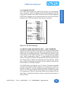
All wiring terminations and adjustments are located inside the P3000. Figure
2-1 shows the P3000 with the access plate removed. General components
referenced in following chapter are labeled. Please note that P3000 display
comes in 4 sizes. Figure 2-1 shows one of the smallest units. The access
area is the same on all units, but the access location is different.
11-position RS-422A
Serial/Repeater Port
Control
Board
Switches SW1,
SW2, and SW3
3 Wire-Clamp
Screw Power
Terminal
Power Jumpers
Fuse
Figure 2-1. Back View of the P3000 Marquee Slave Display with Access
Plate Removed
2.1 SLAVE INTERFACING
Terminal blocks are located inside the P3000. There are two 7/8"holes
drilled in the access plate to accommodate routing the communication
and power cables in and out of the cabinet (for 1/2" conduit fittings).
2.1.1 Power Input Terminals
Three terminals are provided for connecting operating power to the unit.
These terminals are located on the Control Board (see figure 2-1, above).
Power Input terminals are labeled L1, L2, and chassis ground (///). Always
connect the ground terminal to the safety ground. Also located on the
Control Board (and shown on figure 2-1) are the Power Jumpers and the
Fuse.
The P3000 slaves are shipped from the factory set for 115 VAC operation.
Refer to paragraph 2.4 to reconfigure these slaves for 230 VAC operation.
2.1.2 RS-422A SERIAL/REPEATER PORT
The RS-422A Serial/Repeater Port is an 11-position terminal block through
which all communications to the unit take place. This port is located on the
Control Board. The P3000 Control Board and its components is shown in
figure 2-2.
10
Phone: 1-563-359-7501 • Fax: 1-563-359-9094 • www.uticor.net
MAN-P3000-001
P3000 Slave Marquee
Unit Hardware
Introduction
Please note that fuse
rating varies with the
model
Figure 2-2. P3000 Control Board Components
The P3000 also has alternative RS-232C transmission capabilities (see
paragraph 2.1.3). Typical wiring options for the Serial/Repeater Port are
found in figure 2-3 on the next page.
The following text refers to figure 2.3 on the next page.The two
configurations at the top can be used to interface slave units to either a
Master PMD or to a computer or PLC when only unidirectional
communication is to take place. The two configurations on the bottom are
for bidirectional communication which can only take place using computer
control. The PMD master in the third from the top configuration is optional
and is not controlling the slave. Notice that since PMD masters do not
have repeater ports, they can only begin daisy-chains and cannot be
included anywhere within the chain. Daisy-chain wiring provides signal
boosting through the repeater circuits of each slave, and a 4000 foot
distance between each device is possible. (No provision is made for
boosting the reply channel, however.)
An RS-422 “link” consists of a two-wire transmitting line, a two-wire receiving
line (optional), signal common and the shield that is usually terminated to
safety ground. Each two-wire line should physically be implemented with
the two wires of one of the twisted pairs in the cable. (The cable specified
for RS-422 connections consists of three twisted pairs.) Each twisted pair
is individually shielded, and each shield is brought out to a drain wire. DO
NOT USE WIRES FROM DIFFERENT TWISTED PAIRS TO MAKE UP A
TWO-WIRE SIGNAL LINE.
MAN-P3000-001
Phone: 1-563-359-7501 • Fax: 1-563-359-9094 • www.uticor.net
11
Unit Hardware
P3000 Slave Marquee
Note: Reference
designation levels of the
terminals when using
figure 2-4 for wiring
purposes.
All RS-422 connections
should be made with
cable of similar or
superior specifications
and characteristics to
those specified for *
Belden cable number
9730.
* Belden is a registered
trademark of Belden
Electrical Wire Products, a division of
Cooper Industries.
Figure 2.3 RS-422A Serial/Repeater Port Interfacing
12
Phone: 1-563-359-7501 • Fax: 1-563-359-9094 • www.uticor.net
MAN-P3000-001
P3000 Slave Marquee
Figure 2-4. RS-232 Interfacing
2.2 SWITCH ONE AND SWITCH TWO — UNIT ADDRESS
Switches One and Two define the Unit Address (the Group and Unit Number
that the slave will respond to). Switch One is an 8-position dip switch and
Switch Two is a 9-position dip switch. These switches are located on the
Control Board of the P3000 (see figure 2-2.) The switches are labeled
open. Open corresponds to a logic 1. All eight positions of Switch One
and the first position of Switch Two determine the Unit Number. Positions
five through eight of Switch Two determine the Group Number. Switch
Two - position nine designates whether the other switches represent two
BCD numbers or two binary numbers.
The P3000 allows Unit Numbers up to 511 binary. The switch selectable
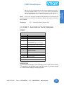
extended U.S./Japanese Kana character set is selected on positions 2
through 4 of Switch 2. Switch 2 positions 2 through 4 settings are: 1) 2-4
Open = U.S. with Japanese Kana extension and 2) 2-4 Closed = Standard
U.S. character set. Figure 2-5 shows how Switch One and Switch Two are
read. Table 2-1 defines the numerical value or setting for each position of
these switches.
MAN-P3000-001
Phone: 1-563-359-7501 • Fax: 1-563-359-9094 • www.uticor.net
13
Unit Hardware
Introduction
2.1.3 P3000 RS-232 PORT
The P3000 Port provides an optional RS-232 port for communication
from a computer. Figure 2-4 (below) shows RS-232 interfacing. RS-232
wiring (from computer to the P3000) should not exceed 50 feet. Additional
P3000 Slave displays can be daisy-chained from the P3000 RS-422
Repeater port. 4000 feet between these slaves is possible.
P3000 Slave Marquee
Unit Hardware
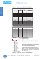
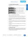
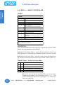
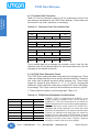
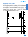
Table 2-1. Switch One and Switch Two Definitions.
SWITCH ONE AND SWITCH TWO UNIT ADDRESS
IDENTIFICATION
SWITCH
BINARY
BCD
DESIGNATION
POSITION
Unit Number
SW1-1
1
1
SW1-2
2
2
Unit Number
Unit Number
SW1-3
4
4
SW1-4
8
8
Unit Number
SW1-5
16
10
Unit Number
SW1-6
32
20
Unit Number
SW1-7
64
40
Unit Number
SW1-8
128
80
Unit Number
SW2-1
256
100
Unit Number
SW2-5
1
1
Group Number
SW2-6
2
2
Group Number
SW2-7
4
4
Group Number
Group Number
SW2-8
8
8
SW2-9
0
1
BCD/Binary
Binary and BCD values refer to when the switch is in the "1" position.
P3000 SLAVE INTERNATIONAL CHARACTER SET
CHARACTER
SW2-2
SW2-3
SW2-4
SET
United States
0
0
0
Cyrillic
1
0
0
French
0
1
0
German
1
1
0
English
0
0
1
Danish
1
0
1
Swedish
0
1
1
Japanese Kana
1
1
1
Reference:
OPEN
3.3 —- Addressing Slaves
4.2.1 — Addressing Slaves
CLOSE
NOTE: For BCD addressing, numbers greater than
9 in any position will have unpredictable results.
CAUTION—Messages sent to unit number zero are
processed by all units within a specified group,
therefore any unit that is assigned a Unit Number of
zero cannot be individually addressed.
In binary numbering, the maximum values are 16
groups (0–15) and 512 units (0–511). When set for
BCD, the maximum values are 10 groups (0–9) and
200 units (0–199).
Figure 2-5. Switch One, Two, and Three Definitions
14
Phone: 1-563-359-7501 • Fax: 1-563-359-9094 • www.uticor.net
MAN-P3000-001
P3000 Slave Marquee
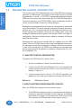
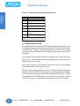
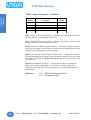
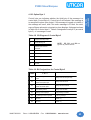
The P3000 also has Switch Three located on its Control Board (see figure
2-3). Switch Three settings are shown in Table 2-2.
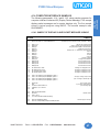
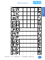
Positions 1 and 2 of Switch Three set the default character height for
displayed messages. The default character height determines what size
the message character will be when character height is not indicated within
the message.
P3000 Slaves can operate at 1200 or 9600 baud. To communicate with a
PMD master, slaves must be set to 9600 baud (factory set). When controlled
by a computer, PLC serial interface, or other intelligent device, the P3000
slave can be set to either 1200 or 9600 baud. To change the baud rate,
you must restart (remove and reapply power) to the unit before the new
baud rate setting is recognized. Baud Rate is set on position 3 of Switch
Three.
To operate in ASCII Mode change the setting as shown on position 4 of
Switch Three. For information about ASCII Protocol, see chapter 5.
Table 2-2. P3000 Switch Three Definitions
SWITCH THREE
CHARACTER HEIGHT/BAUD RATE/PMD MODE/ASCII MODE
DEFAULT IDENTIFICATION
ATTRIBUTE
CHARACTER HEIGHT
TWO-INCH
FOUR-INCH
SIX-INCH
EIGHT-INCH
BAUD RATE 9600
BAUD RATE 1200
PMD MODE
ASCII MODE
POSITION 1
POSITION 2
POSITION 3
POSITION 4
OPEN
CLOSED
OPEN
CLOSED
OPEN
OPEN
CLOSED
CLOSED
-
-
-
-
OPEN
CLOSED
-
OPEN
CLOSED
2.4 CHANGING FROM 115 VAC TO 230 VAC INPUT POWER •
CHANGING THE FUSE
AC powered units can be changed from 115 VAC operation to 230 VAC
operation. This change involves moving internal jumpers and changing
the fuse. All AC units are shipped from the factory set for 115 VAC operation.
MAN-P3000-001
Phone: 1-563-359-7501 • Fax: 1-563-359-9094 • www.uticor.net
15
Unit Hardware
Introduction
2.3 SWITCH THREE — CHARACTER HEIGHT/BAUD RATE/
ASCII MODE
Unit Hardware
P3000 Slave Marquee
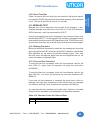
WARNING!! DISCONNECT AC POWER FROM THE UNIT
BEFORE CHANGING THE FUSE or MOVING
JUMPERS!!
To operate the P3000 at 115 VAC (as shipped from the factory):
1W2H/2W2H/1W4H units — the jumpers must be in positions A
and C with 1.5 Amp 250V Slo-Blo fuse*.
2W4H units — the jumpers must be in positions A and C with 3.0
Amp 250V Slo-Blo fuse*.
To operate the P3000 at 230 VAC:
1W2H/2W2H/1W4H units — remove the jumpers from positions
A and C and put one of these jumpers in position B. Replace the
fuse with a 1.0 Amp 250V Slo-Blo fuse*.
2W4H units — remove the jumpers from positions A and C and
put one of these jumpers in position B. Replace the fuse with a
2.0 Amp 250V Slo-Blo fuse*.
* 2AG Subminiature Slo-Blo, 5
mm x 15 mm (.177" x .580")
Figure 2-6. P3000 Jumper Settings for 115/230 VAC Operation and
Fuse Location
2.5 CONCLUSION
Chapter 2 covered the P3000 Slave Marquee hardware. Unit power is
connected to three input power terminals. All communications take place
through the RS-422 Serial/Repeater Port. PMD Slaves are identified by
their unit address that is determined by the positioning of Switch One
and Switch Two. Switch Three lets you select a default setting for display
character size and baud rate, and select ASCII or PMD Mode.
P3000 Slave Marquees also contain jumpers for changing the input power
requirements. Fuse location is also shown in this section. Chapter 3
explains slave operation.
16
Phone: 1-563-359-7501 • Fax: 1-563-359-9094 • www.uticor.net
MAN-P3000-001
PMD Master Control
3
In this chapter....
— Introduction
— Master Control Preparation
— What Happens During Master Control
— Addressing Slaves
— Mixing Displays
— Slave Control by Computer Controlled Master
P3000 Slave Marquee
3.0
PMD MASTER CONTROL INTRODUCTION
PMD Master
Control
The overseer of a P3000 Slave Marquee or any other PMD slave can be a
computer or a PMD master. This chapter covers master control of a P3000
Slave Marquee. Several of UTICOR’s Programmable Message Displays
(PMDs) or touch panels can communicate with the P3000 Slave Marquee.
Consult the manual of your UTICOR PMD or Panel to determine whether it
can be used as a Master Control for a Slave Marquee.
Messages are programmed into the master in a format that is understood
by the slave display. The way a message is displayed (blinking characters,
scrolling text, etc.) is programmed into the message along with the text.
Slaves display the message exactly as the master does (given the
message’s individual display options). But because PMDs vary widely in
configuration, they have dissimilar ways to adapt to messages of different
sizes (discussed later).
Messages with real-time and variable data are updated from the PMD
master. When the P3000 Slave receives new time/date/data information,
the message currently being displayed is updated. While this information
is sent to all slave displays, the P3000 slave displays only messages that
were programmed with an address acceptable to the particular unit. (Refer to paragraph 3.3.)
3.1 MASTER CONTROL PREPARATION
To prepare the P3000 slave for master control:
1.
Set the unit address on Switch One and Switch Two.
2.
Connect the RS-422A Serial/Repeater Port to the programmed
master and other slave(s) as shown in one of the first two examples of Figure 2.3.
3.
Connect service power to the unit. (For 230 VAC operation, you
must move the power input jumpers and change the fuse first.)
Reference:
PMD Master Manual
3.2 WHAT HAPPENS DURING MASTER CONTROL
When the P3000 Slave display is put into master control:
1.
18
The P3000 Slave display is ready to communicate and displays a
message to indicate the software revision code, the unit address
(group and unit number), and the baud rate. (PMD units must be
set to operate at 9600 baud when under master control.)
Phone: 1-563-359-7501 • Fax: 1-563-359-9094 • www.uticor.net
MAN-P3000-001
P3000 Slave Marquee
The P3000 Slave displays this message until the PMD master
begins communicating with the slave(s).
3.
The display clears and then displays the selected message until
the slave is addressed again with a new selected message.
4.
The master sends time and date information to all slaves each
second. Once a slave receives this information, it expects to continue receiving it each second. If seven seconds lapse between
time and date information, the slave displays a “NO COMMUNICATION” message until it receives either the time and date or
until a new message is selected.
5.
Any changes to data set (variable data) information in the master
causes the master PMD to send all four data sets to all slaves.
Only computer interface operation permits selective transmission
of data values (see 3.5).
6.
Time, date and data information are updated continuously on
the P3000 for displayed non-scrolling messages only. Scrolled
messages are updated at each repetition. Please note that the
P3000 will update time, date, and data of static messages when
a scrolling message is being displayed.
7.
Non-scrolling messages can contain blinking characters also
Scrolled messages cannot have blinking characters; stationary
messages can blink but not while a scrolling message is being
simultaneously displayed.
3.3 ADDRESSING SLAVES
Each P3000 or other PMD slave display is assigned a unit address. A unit
address is programmed into each message (programmed for slave output) to specify which unit or units should display that message.
The unit address of a P3000 Slave display is defined by the setting of the
dip switches located inside the back panel under the access plate. These
switches can be changed at any time to alter the address of the unit.
Each unit address consists of two identifiers—a group and a unit number.
The unit addresses are divided into group and unit numbers to allow the
master to address selected subsets of all the PMD displays connected to
it. The following list shows the possibilities:
1. GROUP #00, UNIT #0000 - addresses all units in all groups
2. GROUP #XX, UNIT #0000 - addresses all units in group #XX
3. GROUP #XX, UNIT #XXXX - addresses the specific unit indicated
MAN-P3000-001
Phone: 1-563-359-7501 • Fax: 1-563-359-9094 • www.uticor.net
19
PMD Master
Introduction
Control
2.
P3000 Slave Marquee
PMD Master
Control
When the group and unit number equal zero, messages sent by the master are displayed by all slaves. With a non-zero group number and a unit
number of zero, all units with that group number display the message.
With a non-zero group and unit number, only the display with the indicated
address displays the message.
Reference
2.2 - Switch One and Switch Two
3.4 MIXING DISPLAYS
Displays of all sizes can be used in the same network (a 2-line master with
4-line slaves, etc.). P3000 Slaves can be used with any PMD master (except the PMD 150 that does not have a slave port).
3.5 FEATURES OF THE P3000 SLAVE MARQUEE
The P3000 is offered in several size configurations and has variable character height. Therefore, behavior of the P3000 depends on: message options and the actual message sent, the size of the P3000’s display, character height, and frame definition. Advanced features of the P3000 are
defined in the following paragraphs.
3.5.1 The LED Field
The P3000 display area is composed of up to 8 LED “sticks”. These sticks
are denoted in your display size by the W and H numbers, that is, a 2W4H
display is 2 sticks wide and 4 sticks high. When formatting your message
for your particular size display, keep in mind the display’s stick-height. For
instance, a 4H unit can display:
4
2
1
1
1
lines of 2-inch characters
lines of 4-inch characters
line of 4-inch characters and 2 lines of 2-inch characters
line of 6-inch characters and 1 line of 2-inch characters
line of 8-inch characters
Each stick-height represents a 2-inch high character. Two stick-heights
represents a 4-inch tall character or two 2-inch characters. One stick-width
supports 20 2-inch characters. Two stick-widths support 40 2-inch characters or 20 4-inch characters, etc.
Each stick is 8 LEDs high and 120 LEDs wide. Together, these LED sticks
form the LED display “field”. Character size and field definitions can change
continuously and can be hardware and/or software defined.
3.5.2 Frame Definitions
Frame definition specifies the portion of the LED field that will display the
message. This “enables” a defined number of LED sticks (the entire width
20
Phone: 1-563-359-7501 • Fax: 1-563-359-9094 • www.uticor.net
MAN-P3000-001
P3000 Slave Marquee
Default specification is calculated from the character height specified +
the actual message. For instance, a scroll-left message with 4-inch characters programmed to scroll on line 2 will be displayed on stick 3 and 4
(and leave 2 sticks or one 4" stick-area above it).
Embedded frame definition can be indicated by the first six bytes of the
message sent. This frame definition lets you define “message lines” on
your LED field which helps you set up your P3000 for multiple character
heights and/or multiple message display. This definition must contain 6
bytes. The first 2 bytes indicate the frame definition code - <ESC> <F>.
This is followed by the top stick definition (2 bytes) and the bottom stick
definition (2 bytes). Frame definition is defined as follows:
<ESC><F>(n1)(n2)
n1 is the top stick enabled and represents a 2-digit number between 01
and 04. n1 must be <= the stick-height of the display. n2 must be >= n1
and <= the stick height of the display.
<ESC><F> (in ASCII)
n1 <0><1> to <0><4> (in ASCII)
n2<0><1> to <0><4> (in ASCII)
- 1B 46 (in HEX)
- 30 to 34 (in HEX)
- 30 to 34 (in HEX)
• 2 bytes
• 2 bytes
• 2 bytes
To enter the <ESC> code on your keyboard, enter the ^ character, followed by the [ character. For example, to enable sticks 2-4 enter:
^[F0204
When the top stick specification is larger than (below) the bottom stick
specification, the message will not be displayed.
If no frame definition is specified, the P3000 will specify the frame according to the character height (read from Switch Three settings) and the number of lines in the message.
3.5.3 Character Height
The P3000 supports four character heights: 2-inch, 4-inch, 6-inch, and 8inch characters. P3000 default character height is defined on Switch Three
—positions 1 and 2. When no character definition exists within the message, the message is displayed according to the height set on the dip
switches.
Embedded character-height definitions can be placed anywhere within the
message. All characters following a character-height definition will be disMAN-P3000-001
Phone: 1-563-359-7501 • Fax: 1-563-359-9094 • www.uticor.net
21
PMD Master
Introduction
Control
is always enabled) for message display. This can be done, either by “default” or by frame definition.
P3000 Slave Marquee
PMD Master
Control
played in the specified size until another definition appears (that is, they
are not limited by the end-of-line, just the end-of-message).
Embedded character definitions are as follows:
2-inch = <ESC><0> (in ASCII)
4-inch = <ESC><1> (in ASCII)
6-inch = <ESC><2> (in ASCII)
8-inch = <ESC><3> (in ASCII)
8-inch compressed = <ESC><4> (in ASCII)
- 1B 30 (in HEX)
- 1B 31 (in HEX)
- 1B 32 (in HEX)
- 1B 33 (in HEX)
- 1B 34 (in HEX)
• 2 bytes
• 2 bytes
• 2 bytes
• 2 bytes
• 2 bytes
As mentioned, use the ^[ escape sequence to enter the <ESC> code when
using an ASCII keyboard.
3.5.4 Displaying Messages
When the P3000 receives a message, it will count the number of lines in
the message and assign it a frame according to the number of lines and
the default character height. It first checks for invalid character dimension
sequences. This check looks for character dimensions that will not fit within
the frame specified for the message. A sequence that will not fit is invalid.
Invalid sequences are converted to the maximum character dimension
that will fit within the message’s frame. When no frame is specified, the
P3000 defines the frame according to the default (dip switch) character
size.
For example, when the dip switch is set for 2-inch characters and no frame
is specified, the first four sticks are enabled for a standard message. If the
message contains 4- or 6-inch characters, they will be displayed in their
programmed size and that message line will be located to accommodate
the size. However, lower lines of the message may not fit and therefore
will not be displayed.
Please note the following about P3000 message behavior:
22
1.
A message programmed to clear the display will clear all information from the display prior to displaying itself.
2.
All sticks designated by the message frame will be cleared for
the message. Non-scroll messages with blank lines (end-of-line
marker only) will not clear messages from these lines unless programmed to do so. The size of the blank line (i.e., number of
blank sticks) is determined by the character height preceding the
blank line.
3.
For a standard message, a message line displays only the number of characters physically allowed. The remainder of the message line is truncated.
Phone: 1-563-359-7501 • Fax: 1-563-359-9094 • www.uticor.net
MAN-P3000-001
P3000 Slave Marquee
You may display multiple scroll-up and scroll-left messages at
the same time so long as they do not overlap. All scroll-left messages will move synchronously. Scroll rates for left-scroll messages are fixed and cannot be changed by scroll rate settings of
the master display.
5.
Scroll-up messages of the P3000 behave differently than those
of the vacuum fluorescent displays. P3000 scroll-up messages
wipe onto the display in an upward direction. The P3000 first figures how many message lines can be placed within the frame.
Then these message lines are visually “brushed” across the display from bottom to top, the bottom line of text being revealed
first, on up to the first line.
The display then pauses with this portion of the message, then
clears and repeats the process with the second portion of message lines to fit the frame, etc. The pause time (scroll-up rate
times the number of lines to be unveiled) is determined by:
PMD master default rate
or programmed scroll rate
Example:
×
Number of lines in
the message frame
=
Pause Time
1 second scroll rate x 3 lines = 3 second pause time.
6.
Standard message lines that do not fit the LED field are truncated. Standard messages that do not fit the stick-height structure of the display are truncated.
7.
Blinking characters sent by masters do not blink when using scroll
up or scroll left.
EMBEDDED CODES FOR COMPUTER INTERFACE
When programming packet messages in computer interface for the P3000
display, frame definitions and character height definitions are programmed
as embedded escape codes. For computer interface, escape codes in
Basic are programmed using the escape code CHR$(27). Examples follow:
CHR$(27)+”0"
— TWO-INCH CHARACTER CODE
CHR$(27)+”1"
— FOUR-INCH CHARACTER CODE
CHR$(27)+”2"
— SIX-INCH CHARACTER CODE
CHR$(27)+”3"
— EIGHT-INCH CHARACTER CODE
CHR$(27)+”4"
— EIGHT-INCH COMPRESSED CHARACTER CODE
CHR$(27)+”F”+”nn”+”NN”— FRAME DEFINITION CODE
“nn” indicates top LED stick and ranges from 01 to 04. “NN” indicates the
bottom LED stick, also ranges from 01 to 04, and must be >= “nn”.
MAN-P3000-001
Phone: 1-563-359-7501 • Fax: 1-563-359-9094 • www.uticor.net
23
PMD Master
Introduction
Control
4.
P3000 Slave Marquee
3.6 SLAVE CONTROL BY COMPUTER CONTROLLED MASTER
PMD Master
Control
Several options for control of slave units are available only when the master PMD controlling them is operating via the computer port. These options allow the controlling computer to select, during operation, subsets of
a master’s slaves to receive variable data and to display messages.
This will allow the slaves controlled by one master to display message
data from a number of groups of four data sets. (A master operating in the
normal display mode can send only one group of variable data to all of its
slaves.) It also allows data not sent from a master to be displayed on
selected slaves.
The sequence for these options are as follows (see the Master PMD Manual
for complete descriptions of the commands mentioned below):
1.
The control computer sends a Select Active Slave command
(Code 15) to the master PMD. The data in the command will
specify which of the master’s slaves are to be made active, and
which to be made inactive.
2.
The master passes the Select Active Slave command on to its
slaves, causing the specified activations and deactivations.
3.
The control computer sends a Write Data Set Data To Master
command (Code 16) to the master. The data contained in the
command will include four sets of variable data and should indicate that the master is to pass the data on to active slaves only.
4.
The master PMD will then retransmit the variable data it received
to the active slaves by sending the Write Data Set Data command (Code 14) with the unit number to select active slaves only
(Group #15, Unit #4095). This will cause active slaves only to
display the message.
5.
Only slaves that were activated will receive the new data. All others will continue to display the data that they had received previously. This sequence can be repeated as many times as needed
to send different data sets to different groups of a master’s slaves.
The same sequence can be used to send messages from the control computer to specific slaves. In this case, the control computer (Step 3 above)
will send the Display Packet Message command (Code 02) to the master
(in place of Code 16). Then the master (Step 4 above) will send the Slave
Display Packet Message command (Code 17) to the slaves (in place of
Code 14) using the address Group #15, Unit #4095. This will cause active
slaves only to display the message.
24
Phone: 1-563-359-7501 • Fax: 1-563-359-9094 • www.uticor.net
MAN-P3000-001
P3000 Slave Marquee
Reference
4.0 - Computer Control
4.2.1 - Addressing Slaves
UTICOR’s PMD Master or Touch Panel Manuals
3.7 CONCLUSION
Because P3000 Slave displays contain no message program, all message text displayed on the slave is received from an outside source. When
controlled by a master, a slave receives its information from the master’s
programmed messages that are, in turn, selected by the device that controls that PMD master.
Information concerning the PMD master display and its message program
is found in PMD (Programmable Message Display) Master User’s Manuals. Reference to those manuals are necessary for programming the master and preparing it for the master/slave network.
The following chapter of this manual covers the alternate method for communication with a P3000 Slave display. With this type of interfacing, the
device controlling the slave display is a computer, and master displays
may or may not be involved. In addition to receiving and displaying message, individual slave displays can also send replies to the computer.
MAN-P3000-001
Phone: 1-563-359-7501 • Fax: 1-563-359-9094 • www.uticor.net
25
PMD Master
Introduction
Control
Notice that with this type of operation, a PMD master display may use the
address active display (Group #15, Unit #4095) addressing described in
4.2.1. Since slaves can only be deactivated using computer interface,
messages addressed to active slaves would be processed by all slaves
(as in Group #00, Unit #0000) when no type of computer control is being
used.
PMD Master
Control
P3000 Slave Marquee
This page intentionally left blank.
26
Phone: 1-563-359-7501 • Fax: 1-563-359-9094 • www.uticor.net
MAN-P3000-001
Computer Control
In this chapter....
— Introduction
— Computer Communication Preparation
— Unit Address
— General Message Format
— Message Codes
— Message Replies
— PMD Message Format
— Message Text
— Computer Interface Samples
4
P3000 Slave Marquee
4.0
COMPUTER CONTROL INTRODUCTION
Computer
Control
The P3000 Slave Display may also receive its information from a computer (mainframe, minicomputer, personal computer or PLC ASCII interface that can handle 8-bit binary). By sending data in a format similar to
that used in the memory of a PMD master display (in 8-bit binary), a computer can display messages directly on P3000 Slave displays without the
use of a master. Using this mode of communication, the slave will respond to communication messages it receives and send replies to the
controlling device.
If you have a slave with which you are going to use ASCII protocol, you
should refer to Chapter 5. This chapter will be of little or no use to you.
This chapter of the manual describes the communication protocol that is
acceptable to the P3000 and the commands to which it will respond. This
protocol is of the same design as the computer interface format for the
PMD Master Display. Each user will have to develop a program for his
control computer using the commands and protocol that follow.
4.1 COMPUTER COMMUNICATION PREPARATION
For computer communication, the P3000 Slave RS-422A Serial/Repeater
Port is set to the following parameters:
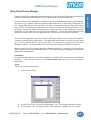
Baud Rate
Stop Bits
Parity
Checksum
=
=
=
=
9600 or 1200 Baud
1 Stop Bit
No Parity
XOR checksum
The baud rate is switch selectable. This switch (SW3) is located on a
circuit board inside the unit. The unit is shipped from the factory with this
switch set for 9600 baud communication. To change the port to 1200 baud,
refer to Chapter 2.
For information concerning the XOR checksum, refer to Appendix A.
Use the following procedure to prepare for computer communication with
P3000 Slave display(s):
28
1.
Set computer parameters to match those of the P3000 Slave. If
necessary, change baud rate on the slave unit.
2.
Connect serial port of the computer to the RS-422A Serial Port(s)
of the P3000. Refer to figure 2-3 to construct appropriate cable(s),
and proper connections.
3.
Connect power to the Power Input Terminal Block.
Phone: 1-563-359-7501 • Fax: 1-563-359-9094 • www.uticor.net
MAN-P3000-001
P3000 Slave Marquee
The P3000 Slave display(s) will be ‘active’ and ready to
communicate. The unit(s) will display a message to indicate the
software revision number, the unit address, and the baud rate.
Reference
2.2 - RS-422A Serial/Repeater Port
2.3 - Switch Three — Character Height/Baud Rate/ASCII
Mode
Appendix A - XOR Checksum
4.2 UNIT ADDRESS
Each P3000 or other PMD slave display is assigned a unit address. A unit
address is sent in each message to specify which unit or units should
respond.
The unit address in a communications message consists of two bytes which
contain two identifiers. These identifiers consist of a group number and a
unit number and are located at Byte 2 and Byte 3 of the communications
message. Refer to figure 4-1 for bit assignments of the unit address bytes.
UNIT ADDRESS
UNIT NUMBER
B0 B1 B2 B3 B4 B5 B6 B7
LEAST SIGNIFICANT BYTE
(SECOND ADDRESS BYTE)
GROUP NO.
B0 B1 B2 B3 B4 B5 B6 B7
MOST SIGNIFICANT BYTE
(FIRST ADDRESS BYTE)
Figure 4-1. Unit Address Byte Designation
The unit address of a P3000 Slave display is defined by the setting of the
dip switches located on the control board behind the access plate on the
back of the unit, see figure 2-2. The unit address will only be read from
these switches during power up transition.
Reference
2.2 - Switch One And Switch Two — Unit Address
4.2.1 Addressing Slaves
The unit address is divided into group and unit numbers to allow the
controlling computer to communicate with selected subsets of all the P3000
Slave displays connected to it. The following list shows the possibilities:
1.
2.
3.
4.
MAN-P3000-001
Group #00, Unit #0000 — addresses all units in all groups
Group #XX, Unit #0000 — addresses all units in group #XX
Group #15, Unit #4095 — addresses all ‘active’ slave units
Group #XX, Unit #XXXX — addresses the specific unit indicated
Phone: 1-563-359-7501 • Fax: 1-563-359-9094 • www.uticor.net
29
Computer
Introduction
Control
4.
P3000 Slave Marquee
Computer
Control
When the group and unit number equal zero, messages broadcast by the
control computer will be processed by all units attached.
With a non-zero group number with the unit number of zero, all units with
that group number will process the message.
Messages sent to Group #15 and Unit #4095 will be processed by all
slave units that are currently ‘active’ and ignored by all ‘inactive’ slaves.
Reference
4.2.2 - Active/Non-Active Slave Units
4.9 - Select Active Slave
When a message sent to an individual display is received, that display
sends a reply to the control computer. When a message is received that
used any of the above mentioned address grouping techniques, no reply
is returned. Note that certain messages (those that require a reply other
than the standard reply) cannot be processed when the units are addressed
by any of the grouping techniques. The specific message types which
cannot be processed with these techniques are noted in Table 4-1
WARNING! Do NOT use the same unit address for PMDs that are
connected together serially using bidirectional communications. This
could result in more than one reply to a computer interface command.
If more than one reply is sent on the serial line, the serial drivers of
the PMDs may become damaged.
Note: The unit address is only read when the unit is powered up.
4.2.2 Active/Non-Active Slave Units
The computer interface protocol provides another means to send messages
to specific collections of P3000 Slave units beyond using group numbers.
A computer interface command is provided to allow the controlling computer
to ‘activate’ or ‘de-activate’ the slaves connected to it. Slaves power up
‘activated’ and the controlling computer can, by group or individual unit,
activate or deaactivate the slaves. Then it can utilize the Group #15, Unit
#4095 addressing mode described in 4.2.1.
Reference
30
4.9 - Code 15 - Select Active Slave
Phone: 1-563-359-7501 • Fax: 1-563-359-9094 • www.uticor.net
MAN-P3000-001
P3000 Slave Marquee
General message format for messages sent via computer is shown below
in figure 4-2.
HEX AA
One byte — indicates start of message
LENGTH
One byte — indicates message length
UNIT ADDRESS
Two bytes — indicates unit’s address
MESSAGE CODE
One byte — Code for message type
DATA
X bytes — Message/reply data bytes
CHECKSUM
Two bytes — See Appendix A Checksum Bytes
Figure 4-2. Message Format For Computer
Note that all messages, including replies sent from the P3000 Slave, must
begin with a hex byte equal to AA to indicate the start of a message.
Also note that the checksum of a message is calculated by using the bytes
that represent: Length, Unit Address, Message Code, and Data. (See
Appendix A.)
The length byte is always the length of the entire communications message,
less one (for the AA). The length specifically does include the length byte
and checksum.
Unit address bytes are stored most significant byte first, least significant
byte second.
Except where noted otherwise, all parts of the message are composed of
Hex bytes (as opposed to ASCII or BCD).
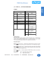
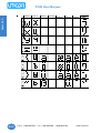
4.4 MESSAGE CODES
Message codes are required to define the type of communication to take
place. The P3000 Slave is programmed to process various types of
messages, and these have been assigned Message Code Numbers. Table
4-1 defines message code numbers.
MAN-P3000-001
Phone: 1-563-359-7501 • Fax: 1-563-359-9094 • www.uticor.net
31
Computer
Introduction
Control
4.3 GENERAL MESSAGE FORMAT
P3000 Slave Marquee
Computer
Control
Table 4-1. Message Code Number Designations
CODE
COMMAND
00
STANDARD REPLY
13
SET TIME AND DATE
14
WRITE DATA SET DATA
15
SELECT SLAVE(S)
17
SLAVE DISPLAY PACKET
MESSAGE
*18
STATUS/ID MESSAGE
Note: All numbers are in decimal.
*Allowed only when individual units are addressed.
4.5 MESSAGE REPLIES
All messages sent to individual P3000 Slave displays (as opposed to any
of the group addressing techniques described in 4.2.1) will cause the slave
to send a reply. The reply will indicate the success or failure of processing
the command and will indicate that the display is ready to process another
command.
In most cases, this message will be the “standard reply” described in the
next section. One command (Status/ID Message) will cause the unit to
send a special form of reply.
The following section of this chapter covers the format of the message
codes and provides a description of each.
The time delay between when the control computer finishes sending a
command until the P3000 Slave begins to reply depends upon the specific command and the amount of data sent with the command. P3000
Slave displays, like the PMD master, do not “stack” commands. It is best
to wait for a reply to a command before sending any more commands.
32
Phone: 1-563-359-7501 • Fax: 1-563-359-9094 • www.uticor.net
MAN-P3000-001
P3000 Slave Marquee
Computer
Introduction
Control
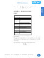
4.6 CODE 00 — STANDARD REPLY FORMAT
FORMAT
REPLY
BYTE NUMBER
VALUE
1
HEX AA = Start of Message Byte
2
8 Length
3
B1–B3 = Not Used
B0 = Most Significant Bit of 9-Bit Unit Number
4
8 Least Significant Bits of 9-bit Unit Number
5
00 Message Code
6
Message Code of Received Message
7
Reply Error Code
0 = No Error
1 = Checksum Error
2 = Timeout
3 = Invalid Message Code
8 = Invalid Message Length
8
Checksum (2 bytes) LSB, MSB
DESCRIPTION
This is the standard format for a P3000 Slave reply to the computer. When
using the message commands described in this section, refer to this chart
whenever a message command chart indicates that the reply is of standard
format.
MAN-P3000-001
Phone: 1-563-359-7501 • Fax: 1-563-359-9094 • www.uticor.net
33
P3000 Slave Marquee
Computer
Control
4.7 CODE 13 — SET TIME AND DATE
FORMAT
COMMAND
BYTE NUMBER
VALUE
1
HEX AA = Start Of Message Byte
2
13 Length
3
B4-B7 = 4-Bit Group Number
B1-B3 = Not Used
B0 = Most Significant Bit of 9-bit Unit Number
4
8 Least Significant Bits of 9-bit Unit Number
5
13 Message Code
6
HOUR MODE: 0 = 12 Hour Mode, 1 = 24 Hour
Mode
7
HOURS: 1–12 for 12 Hour Time (D7 = 1 = PM)
0–23 for 24 Hour Time
8
MINUTES: 00–59
9
SECONDS: 00–59
10
MONTHS: 1–12
11
DATE: 1–31
12
YEAR: 00–99
13
Checksum (2 bytes) LSB, MSB
REPLY = STANDARD REPLY
DESCRIPTION
This command, when processed by a P3000 Slave display, will store the
real-time information contained in the command in the slave displays
addressed. This will update the time and date currently being displayed in
a message once the command has been processed. When sent to a
single slave display, a standard reply will be returned to the computer.
Byte 6 (Hour Mode)— select 12 or 24 hour mode. Only used bits of this byte should
be set. All other bits should be kept to ‘0’.
Byte 7 (Hours) —when Byte 6 selects the 12-hour format, the hours byte indicates
AM or PM in the high bit (D7). D7 of byte 7: 0 = AM, 1 = PM
NOTES: When controlled by a master PMD, a slave display has its time
and date updated every 1 second.
When the P3000 Slave unit is communicating via computer control, the
“NO COMMUNICATIONS” timeout error is disabled.
34
Phone: 1-563-359-7501 • Fax: 1-563-359-9094 • www.uticor.net
MAN-P3000-001
P3000 Slave Marquee
3.2 - What Happens During Master Control
C.1 - PMD Master Control Errors
Computer
Introduction
Control
Reference
4.8 CODE 14 — WRITE DATA SET DATA
FORMAT
COMMAND
BYTE NUMBER
VALUE
1
HEX AA = Start Of Message Byte
2
15 Length
3
B4-B7 = 4-bit Group Number
B1-B3 = Not Used
B0 = Most Significant Bit of 9-bit Unit Number
4
8 Least Significant Bits of 9-bit Unit Number
5
14 Message Code
6
Status Byte: 0 = BCD, 1 = Binary
7
Data Set 1 (2 bytes) MSB, LSB
9
Data Set 2 (2 bytes) MSB, LSB
11
Data Set 3 (2 bytes) MSB, LSB
13
Data Set 4 (2 bytes) MSB, LSB
15
Checksum (2 bytes)
REPLY = STANDARD REPLY
DESCRIPTION
This command is used to define the values of the four data sets used by
the P3000 Slave. All four data sets must be defined in the command. The
data sent by this command will be used by the P3000 Slave(s) to which it
is addressed.
Byte 6 (Status Byte) - indicates whether the data is BCD or binary.
0 = BCD
1 = Binary
MAN-P3000-001
Phone: 1-563-359-7501 • Fax: 1-563-359-9094 • www.uticor.net
35
P3000 Slave Marquee
Computer
Control
4.9 CODE 15 — SELECT ACTIVE SLAVE
FORMAT
COMMAND
BYTE NUMBER
VALUE
1
HEX AA = Start Of Message Byte
2
7 + X Length
3
B4-B7 = 4-bit Group Number
B1-B3 = Not Used
B0 = Most Significant Bit of 9-bit Unit Number
4
8 Least Significant Bits of 9-bit Unit Number
5
15 Message Code
6
Active Units Control Byte
7
X amount of data in the form of 2 byte group and
unit numbers. Form is the same as bytes 3 and 4
in message.
*7+X
Checksum (2 bytes)
REPLY = STANDARD REPLY
* X must be less than, or equal to, 248, which can represent 124
(Group, Unit) number combinations.
DESCRIPTION
This command allows the control computer to specify which of the P3000
Slaves are to be activated or de-activated.
Bytes 3 & 4 (Unit Address Bytes) — specify the unit and group number of the
slave displays to be affected by the command (typically Group #0, Unit #0).
Byte 6 (Active Units Control Byte) — this byte is used to specify the application of
the activate or de-activate command to the various slaves. (Refer to Table 4-2.)
Table 4-2. Byte 6 - Active Unit Control Byte
B7
B0
APPLICATION
0
0
De-activate specified slaves only
0
1
Activate specified slaves only
1
0
De-activate specified slaves — Activate other slaves
1
1
Activate specified slaves — Deactivate other slaves
Bit 0 of this byte indicates the requested state of the slaves whose
addresses are contained in the list beginning at Byte 7. A “1” in this
position indicates those slaves are to be activated. A “0” indicates they
should be de-activated.
36
Phone: 1-563-359-7501 • Fax: 1-563-359-9094 • www.uticor.net
MAN-P3000-001
P3000 Slave Marquee
Byte 7 — A list of unit and group numbers of slave displays to be activated or deactivated. Note that only units in the address at Bytes 3 and 4 will be affected by
this command.
Reference
4.2.2 - Active/Non-Active Slave Units
4.10 CODE 17 - SLAVE DISPLAY PACKET MESSAGE
FORMAT
COMMAND
BYTE NUMBER
VALUE
1
HEX AA = Start of Message Byte
2
10 + X Length
3
B4–B7 = 4-bit Group Number
B1–B3 = Not Used
B0 = Most Significant Bit of 9-bit Unit Number
4
8 Least Significant Bits of 9-bit Unit Number
5
17 Message Code
6
Blink ON Time Interval
7
Blink OFF Time Interval
8
Time Interval between upward Scrolls
9
Time Interval between right to left Scrolls
* 10 + X
Checksum (2 bytes)
REPLY = STANDARD REPLY
* X must be less than, or equal to, 235.
DESCRIPTION
This command will display a valid message on the P3000 Slave’s display.
The message to be displayed must follow the format of a stored message
in a PMD master display’s message program.
MAN-P3000-001
Phone: 1-563-359-7501 • Fax: 1-563-359-9094 • www.uticor.net
37
Computer
Introduction
Control
Bit 7 of this byte indicates what all other slaves (addressed by Bytes 3
& 4) status should become. If it is a “0”, all of the other slaves activation
status is unchanged by this command. If it is set to “1”, all other slaves
are activated when bit 0 is a “0” and de-activated when bit 0 is a “1”.
P3000 Slave Marquee
Computer
Control
Table 4-3. Bytes 6 through 9 — Definitions
BYTE
NUMBER
ATTRIBUTE
VALID
VALUES
6
Blink On Time Interval
1–99
7
Blink Off Time Interval
1–99
8
Time Interval Between Upward Scrolls
1–99
9
Time Interval Between Right-to-Left Scrolls
1–99
Byte 6 (Blink On Time Interval Byte) — indicates the length of time that each
blinking character of the message will blink on.
Byte 7 (Blink Off Time Interval Byte) — indicates the length of time that each
blinking character of the message will blink off.
Byte 8 (Time Interval Between Upward Scrolls) — indicates the length of time that
each line of message text will remain on each line of the display before being
replaced by the subsequent line of the message.
Byte 9 (Time Interval Between Right-To-Left Scrolls) — indicates the length of
time that each character will remain at each character location as it moves across
the display. Valid values for Bytes 6 through 9 range from 1 (0.1 second) to 99
(9.9 seconds).
Byte 10 (First Message Text Byte) — is where the message to be displayed
begins. As specified in paragraph 4.12, the first byte of the message to be
displayed is the length byte. It must occupy Byte 10, followed by the balance of
the message.
Reference
38
4.12 - PMD Stored Message Format
4.12.1 - Message Example
Phone: 1-563-359-7501 • Fax: 1-563-359-9094 • www.uticor.net
MAN-P3000-001
P3000 Slave Marquee
Computer
Introduction
Control
4.11 CODE 18 — STATUS/ID MESSAGE
FORMAT
COMMAND
REPLY
BYTE
NUMBER
VALUE
BYTE
NUMBER
VALUE
1
HEX AA = Start of Message
Byte
1
HEX AA = Start of Message
Byte
2
6 Length
2
9 Length
3
B4–B7 = 4-bit Group Number
B1–B3 = Not Used
B0 = MSB of 9-bit Unit Number
3
B4–B7 = 4-bit Group Number
B1–B3 = Not Used
B0 = MSB of 9-bit Unit
Number
4
8 Least Significant Bits of 9-bit
Unit Number
4
8 Least Significant Bits of 9-bit
Unit Number
5
18 Message Code
5
18 Message Code
6
Checksum (2 bytes)
6
Device Type: HEX 01 = 200
Master
HEX 02 = 300 or 400 Master
HEX 82 = 200 Slave
HEX 83 = 300 or 3000 Slave
HEX 8D = 3500 Slave
7
Revision Code: ASCII
Character for Revision Letter
HEX 41 = Revision A
HEX 42 = Revision B
8
State: Active = 1,
Non-Active = 0
9
Checksum (2 bytes)
DESCRIPTION
This command requests status and ID information from a P3000 Slave
display. The command must be sent to a specific display to get a reply.
The (nonstandard) reply contains the requested information.
Reply Description:
Byte 6 (Reply Device Type) — identifies the addressed device as either a master
or slave PMD. This byte will equal 83 to indicate that it is a P3000 Slave display.
Byte 7 (Reply Revision Code) — indicates the revision code letter of the software
in the display and will be in the form of an ASCII character. (HEX revision codes
shown in the table are examples only.)
Byte 8 (Reply State) — indicates whether the P3000 Slave is active or non-active.
Reference
MAN-P3000-001
4.2.2 - Active/Non-Active Slaves
4.9 - Select Active Slave
Phone: 1-563-359-7501 • Fax: 1-563-359-9094 • www.uticor.net
39
P3000 Slave Marquee
Computer
Control
4.12 PMD MESSAGE FORMAT
The formats for message storage within a PMD master’s memory and for
messages sent from a control computer to a master or slave display is
shown in Table 4-4. This is the structure of the “Message To Display” in
Code 17. The beginning of the message is made up of option selection
bytes. Depending on the message options selected, the number and
meaning of option bytes vary. There are seven different message formats. Three of these formats pertain to master PMDs only.
Which of the four formats that pertain to slaves is appropriate depends
upon the options required by the message. Table 4-5 relates the selected
options to the formats shown in Table 4-4 (A)-(D). For example, a message with no options selected, would be structured as shown in 4-4 (A). A
message that should scroll left would be formatted as in 4-4 (C).
Table 4-4. Message Format of PMDs
BYTE
1
2
3
4
5
6
FORMAT
A
LENGTH
BYTE (n)
CONTROL
BYTE #1
MSG
DATA
FORMAT
B
LENGTH
BYTE (n)
CONTROL
BYTE #1
CONTROL
BYTE #2
MSG
DATA
FORMAT
C
LENGTH
BYTE (n)
CONTROL
BYTE #1
CONTROL
BYTE #2
SCROLL
OPTIONS
MSG
DATA ------------------
LAST BYTE
MSG/DATA
FORMAT
D
LENGTH
BYTE (n)
CONTROL
BYTE #1
CONTROL
BYTE #2
SCROLL
OPTIONS
SCROLL
TUNE
LAST BYTE
MSG/DATA
-------------------------------------------------------------------------------------------
MSG
DATA
n
LAST BYTE
MSG/DATA
LAST BYTE
MSG/DATA
Table 4-5. Message Options Versus Message Formats
FORMAT A
Chained, Printout, Print On One Line, Send <CR><LR> At
Message End Clear Display, Center Message
FORMAT B
Same as Format A, plus Energize Alarm, Blink Entire Message
FORMAT C
Same as Format B, plus Scroll up, Scroll Left, Repeat Message
FORMAT D
Same as Format C, plus Select Scroll Time Interval
NOTE: Slaves receiving formats which contain slave addresses (Formats E, F, and
G shown in the PMD master manual) will ignore those slave addresses in the
message.
40
Phone: 1-563-359-7501 • Fax: 1-563-359-9094 • www.uticor.net
MAN-P3000-001
P3000 Slave Marquee
Figure 4-3 illustrates a “byte diagram” of a message example to show
how bytes are utilized in message memory. The third through sixteenth
bytes in this example represent the message data itself and are contained
in the message/data bytes area shown in Table 4-4.
The column on the left shows the actual Hex bytes which make up the
message. The other column is in decimal, binary, or ASCII, for ease of
interpretation.
HEX
CODE
10
16
10
00010000
41
A
20
Indicates that the message text is 16 bytes long
(Byte 1 in table 4-4)
Indicates the message is centered (Byte 2 in table
4-4). Up to 6 control bytes are used for each
message (1 control byte per message minimum)
*** Location of optional frame definition code for the
P3000 Slave
‘A’ is the first character of the first line
<SPACE> byte
4D
M
53
S
47
G
2E
.
FF
FF
53
S
41
A
4D
M
50
P
4C
L
45
E
FF
FF
End of line marker for line 1
‘S’ is the first character of the second line
End of line marker for line 2
Figure 4-3. Message Example Byte Diagram
.
As shown in Figure 4-3, every byte needed to represent the message
counts as a byte of the message and is counted as part of the total size of
the message. Notice that the length byte also counts itself.
MAN-P3000-001
Phone: 1-563-359-7501 • Fax: 1-563-359-9094 • www.uticor.net
41
Computer
Introduction
Control
4.12.1 Message Example
P3000 Slave Marquee
Computer
Control
4.12.2 Control Byte 1
Control byte one selects some of the options possible for the message. A
diagram of this byte is shown in Table 4-6 to illustrate the definitions of the
8 bits of this byte. Table 4-7 designates how byte 2 of each message is
read.
Table 4-6. Bit Diagram of Control Byte 1
B7
Chained Msg Bit
B6
Clear Display Bit
B5
Send to RS-232 Bit
B4
Center Message Bit
B3
On One Line Bit
B2
<CR><LF> Bit Repeat Chain Bit
B1
Control Character Bit
B0
Byte 3 Bit
NOTE: B7 — Slave displays do not
support chained messages. If this bit is
set, the message will not be displayed.
B5, B3, & B2 — Refer to RS-232 port
printouts on master PMD and are ignored
by slaves.
B1— Set if message contains any ASCII
control characters (HEX 00-1F). (Does
not include time, date, or data set
characters.)
B0 — Set to enable second options byte.
Table 4-7. Bit Designations for Control Byte 1
BIT
NUMBER
42
IF BIT = 1
IF BIT = 0
B7
Message is Chained
Message is Not Chained
B6
B7 = 0 then Overlay
Existing Msg
B7 = 1 then Repeat Chain
Message Clears Display
Chain Does Not Repeat
B5
Send Message to RS-232
Do Not Output Message
B4
Center Message
Message Not Centered
B3
Send on One Line (B5 must
equal 1)
Send on Multiple Lines (B5 must
equal 1)
B2
<CR><LF> at end of
Message (B5 must equal 1)
No <CR><LF> at end of Message
(B5 must equal 1)
B1
Message has Control
Characters
No Control Characters
B0
Byte 3 Control Byte
No More Control Bytes
Entire Msg Does Not Blink or Scroll
No Relay Alarm Output
Message Not Logged or Invisible
Message Not Sent to Slave
Phone: 1-563-359-7501 • Fax: 1-563-359-9094 • www.uticor.net
MAN-P3000-001
P3000 Slave Marquee
Control byte one indicates whether the third byte of the message is a
control byte (Control Byte 2). Control byte 2 will indicate if the message is
to energize the alarm relay output, if the message is logged or invisible, if
the message will scroll, and if the entire message is to blink. As noted,
some of these options do not pertain to slave displays. A diagram is shown
in Table 4-8 of control byte 2. Table 4-9 designates how byte 3 (as control
byte 2) of a message is read.
Table 4-8. Bit Diagram of Control Byte 2
B7
Energize Alarm Relay Output
B6
Scrolled Message Bit
B5
Message Sent to Slave Bit
Indicates 2 bytes after last
control byte
B4
Blink Entire Message Bit
B3
Invisible Msg Bit
B2
Log Message Bit
B1
Not Used
B0
Not Used
NOTE: B7, B3, and B2 are
ignored by P3000 Slaves.
Table 4-9. Bit Designations for Control Byte 2
BIT
NUMBER
MAN-P3000-001
IF BIT = 0
IF BIT = 1
B7
Message Energizes Alarm Relay
Output
Message Does Not Energize Relay
B6
Message Scrolls
Enable Scroll Options Byte
Message Does Not Scroll
B5
Message Sent to Slaves
Enable Unit Number Bytes
Message Not Sent to Slaves
B4
Entire Message Blinks
Message Does Not Blink
B3
Message is Not Displayed
Display Message on Master
B2
Log Message on Data Log Stack
Do Not Log Message
B1
Not Used
(Default = 0)
B0
Not Used
(Default = 0)
Phone: 1-563-359-7501 • Fax: 1-563-359-9094 • www.uticor.net
43
Computer
Introduction
Control
4.12.3 Option Byte 2
P3000 Slave Marquee
Computer
Control
4.12.4 Scroll Options Byte
As noted previously in 4.12.3, if control byte two indicates that a message
will scroll, a third control byte (byte 4) is necessary to determine control
options for scrolling. Table 4-10 shows a diagram of byte 4 as the scroll
option control byte. Table 4-11 designates how byte 4 (as control byte 3)
of a message is read.
Table 4-10. Bit Diagram of Control Byte 3
B7
Scroll Time Byte Enable
B6
Repeat Message Bit
B5
Display Lines to Scroll Msg On Bit
B4
Display Lines to Scroll Msg On Bit
B3
Display Lines to Scroll Msg
B2
Display Lines to Scroll Msg
B1
Scroll Msg Right to Left Bit
B0
Scroll Msg Up Bit
Table 4-11. Bit Designations for Control Byte 3
BIT
NUMBER
IF BIT = 1
IF BIT = 0
B7
Message Contains Scroll
Time Interval Information in
Byte 5
Message Does Not Contain
Scroll Time Interval
B6
Message Repeats
Message Does Not Repeat
B5
Message Scrolls on Line 4
Message Does Not Scroll on Line 4
B4
Message Scrolls on Line 3
Message Does Not Scroll on Line 3
B3
Message Scrolls on Line 2
Message Does Not Scroll on Line 2
B2
Message Scrolls on Line 1
Message Does Not Scroll on Line 1
B1
Scrolls Right to Left
Message Does Not Scroll Left
B0
Message Scrolls Upward
Message Does Not Scroll Upward
NOTE: B2– B5 — Select which lines of the display a scrolling message will be
displayed on. For left-scrolling messages, one of these bits must = “1” and the
other three must = “0”. For upward-scrolling messages, one, two, three, or four
contiguous lines can be set.
44
Phone: 1-563-359-7501 • Fax: 1-563-359-9094 • www.uticor.net
MAN-P3000-001
P3000 Slave Marquee
4.13 MESSAGE TEXT
Message text is to be entered as the last part of the message. A nonscrolling message must have two or four lines of 0 to 40 (230 maximum)
ASCII characters, each line terminated by HEX FF.
A scrolling message’s text can be composed of any number of lines, each
terminated by HEX FF. The total length of the message, including all control
bytes and the size byte must be 235 characters or less. P3000 Slave scrollup time interval can vary, but scroll-left time is fixed and cannot be changed.
4.13.1 Blinking Characters
Blinking of individual characters is coded into the message text by setting
the most significant bit (B7) of the byte of the ASCII character to be blinked.
Blink delimiters are not used in the stored message format. Also, note
that time, date, and data set bytes have the most significant bit set, but
cannot be made to individually blink.
4.13.2 Time and Date Characters
To enter the time into a message, enter the Hex character code for the
time (HEX 81) eight times (to represent the eight time characters
HH:MM:SS).
To enter the date into a message, enter the Hex character code for the
date (HEX 82) nine times (to represent the nine date characters DDMMM-YY).
If you enter too few characters to represent the entire time or date in a
message, the right-most character(s) will be deleted from the message.
For instance, entering 5 time characters will represent HH:MM only.
You may place the time and date next to each other. Two time or two date
strings must be separated by a displayable non-time/date character.
Table 4-12. Character Codes For Time and Date
MAN-P3000-001
HEX 81
Character Code Used to Indicate Character of Time in a Message
HEX 82
Character Code Used to Indicate Character of Date in a Message
Phone: 1-563-359-7501 • Fax: 1-563-359-9094 • www.uticor.net
45
Computer
Introduction
Control
4.12.5 Scroll Time Byte
If byte 5 is used as the scroll time byte, the contents of the byte will specify
how often the P3000 Slave will shift the scrolled message, either upwards
or left. The time is specified in units of 0.1 seconds.
P3000 Slave Marquee
Computer
Control
4.13.3 Variable Data Characters
Table 4-13 lists the character codes for all five characters of each of the
four data sets maintained by the P3000 Slave displays. These codes can
be entered in any order, anywhere in a message.
Table 4-13. Character Codes For Variable Data
CHARACTER CODES USED TO REPRESENT DATA SET # 1 CHARACTERS
MSD
LSD
HEX 85
HEX 86
HEX 87
HEX 88
HEX 89
CHARACTER CODES USED TO REPRESENT DATA SET # 2 CHARACTERS
MSD
LSD
HEX 8A
HEX 8B
HEX 8C
HEX 8D
HEX 8E
CHARACTER CODES USED TO REPRESENT DATA SET # 3 CHARACTERS
MSD
LSD
HEX 8F
HEX 90
HEX 91
HEX 92
HEX 93
CHARACTER CODES USED TO REPRESENT DATA SET # 4 CHARACTERS
MSD
LSD
HEX 94
HEX 95
HEX 96
HEX 97
HEX 98
To put variable data into a message via computer control, enter the Hex
character code for the desired digit(s) for the desired data set(s) into the
message at the desired location(s).
4.13.4 P3000 Slave Embedded Codes
The P3000 Slave reads embedded codes within the message text. These
codes can change character size or specify the frame definition. Character
size codes can be placed anywhere within message text. These codes
toggle the character size between 2", 4", 6", 8", and 8" compressed
characters. A frame definition codes sets up which LED “sticks” will display
the message. This 6-byte code must be located where shown in figure 43. These codes are shown in the following table, Table 4-14.
Table 4-14. P3000 Slave Embedded Code Definitions
Character Size
ASCII Code
HEX Code
2"
<ESC><0>
1B 30
4"
<ESC><1>
1B 31
6"
<ESC><2>
1B 32
8"
<ESC><3>
1B 33
8" Compressed
<ESC><4>
1B 34
Frame Definition Code
Top Stick
Bottom Stick
<ESC><F>
## 2-digit number
## 2-digit number
46
In BASIC, <ESC> is programmed as CHR$(27), so an
escape sequence to enable sticks 3 and 4 would be:
CHR$(27)+”F”+”03"+”04". Note that this is an example for
a BASIC program and will vary for other program languages.
Also note that these codes instruct the P3000 only.
Messages that include character size codes and frame
definitions are displayable on the master and other kinds
of slaves. All characters and digits within the codes are
displayed on units other than the P3000 Slave. To avoid
displaying these extra characters, set up the P3000 Slave
message as invisible to the master. Program a separate
message for master (and other slave) display.
Phone: 1-563-359-7501 • Fax: 1-563-359-9094 • www.uticor.net
MAN-P3000-001
P3000 Slave Marquee
The following paragraphs, 4.14.1 and 4.14.2, show sample programs for
computer interface command 02 (Display Packet Message). The sample
display packet messages are for master displays only. The first sample
shows a typical program using BASIC. The second example uses
QUICKBASIC.
4.14.1 SAMPLE OF DISPLAY SLAVE PACKET MESSAGE IN BASIC
PROGRAM
MAN-P3000-001
COMMENTS
20
OPEN “com1:9600,n,8,1” FOR RANDOM AS #1
25
30
35
40
45
50
55
60
65
70
75
80
85
90
95
MSG(1)=170
MSG(2)=96
MSG(3)=0
MSG(4)=0
MSG(5)=17
MSG(6)=0
MSG(7)=0
MSG(8)=0
MSG(9)=0
MSG(10)=86
MSG(11)=0
MSG(32)=255
MSG(53)=255
MSG(74)=255
MSG(95)=255
100
105
110
115
A$=”FRONT AXLE 12500"
B$=”DRIVE AXLES 31440"
C$=”TRAILER AXLES 36000"
D$=”GROSS WEIGHT 79940"
120
125
130
135
FOR I=1
FOR I=1
FOR I=1
FOR I=1
140
145
150
155
GOSUB 500
END
CLS:INPUT “SEND AGAIN?”;Y$
IF MID$(Y$,1,1)=”Y” THEN 25
END
500
505
510
515
REM CHECKSUM ROUTINE
CKSUM=0
FOR I=1 TO 95
IF I>1 THEN CKSUM=CKSUM XOR MSG(I)
520
525
PRINT #1,CHR$(MSG(I));:NEXT I
PRINT #1, CHR$(CKSUM);CHR$(255-CKSUM)::RETURN
TO 20:MSG(I+11)=ASC(MID$(A$,I,1)):NEXT I
TO 20:MSG(I+32)=ASC(MID$(B$,I,1)):NEXT I
TO 20:MSG(I+53)=ASC(MID$(C$,I,1)):NEXT I
TO 20:MSG(I+74)=ASC(MID$(D$,I,1)):NEXT I
sets RS-232 port for 9.6K baud, no parity, 8 data bits, 1 stopbit
HEX AA, start of message byte
length of message (not including HEX AA)
4-bit group number/1 MSB of 9-bit unit number
8 LSBs of 9-bit unit number
message code 17 = display slave packet message
blink On
blink Off
scroll Up
scroll Left
message to display
message control attributes
end of line marker for line 1
end of line marker for line 2
end of line marker for line 3
end of line marker for line 4
message to be displayed on line 1
message to be displayed on line 2
message to be displayed on line 3
message to be displayed on line 4
message 1-4 being set up in ASCII
(note - message 1 starts as byte 10)
Phone: 1-563-359-7501 • Fax: 1-563-359-9094 • www.uticor.net
go to checksum routine
do you want to send message?
if yes send string again
checksum routine
send message to comm port
47
Computer
Introduction
Control
4.14 COMPUTER INTERFACE SAMPLES
P3000 Slave Marquee
4.14.2 SAMPLE OF DISPLAY SLAVE PACKET MESSAGE IN QUICKBASIC*
Computer
Control
MESSAGE TEXT
ms1$ = “LINE
ms2$ = “LINE
ms3$ = “LINE
ms4$ = “LINE
messages$ =
COMMENTS
1 OF DIS PLAY” + CHR$(255)
2 OF DIS PLAY” + CHR$(255)
3 OF DIS PLAY” + CHR$(255)
4 OF DIS PLAY” + CHR$(255)
ms1$ + ms2$ + ms3$ + ms4$
‘CHR$(255) is end of line marker
‘complete message text
meslength = LEN(message$) + 2
comlength = meslength + 10
*QUICKBASIC
is a registered
trademark of
Microsoft
Corporation.
start = 170
unit1 = 0
unit2 = 0
code = 17
blinkon = 0
blinkoff = 0
scrollup = 0
scrollleft = 0
control = 0
‘message$ + control byte + meslength byte
‘total length less start byte
‘start of command message HEX AA
‘group and unit number
‘unit number
‘command code (S LAV E DIS PLAY PA CK ET MES SA GE)
‘calculate checksum
checksum = 0
checksum = checksum
checksum = checksum
checksum = checksum
checksum = checksum
checksum = checksum
checksum = checksum
checksum = checksum
checksum = checksum
checksum = checksum
checksum = checksum
‘calculate checksum
XOR comlength
XOR unit1
XOR unit2
XOR code
XOR blinkon
XOR blinkoff
XOR scrollup
XOR scrollleft
XOR meslength
XOR control
FOR I = 1 TO LE N(message$)
checksum = checksum XOR AS C(MID$(message$,I,1))
NEXT I
OPE N “COM1:9600,N,8,1” FOR RA NDOM AS #1
P RINT
P RINT
P RINT
P RINT
P RINT
P RINT
P RINT
P RINT
P RINT
P RINT
P RINT
P RINT
P RINT
P RINT
#1,
#1,
#1,
#1,
#1,
#1,
#1,
#1,
#1,
#1,
#1,
#1,
#1,
#1,
CHR$(start);
CHR$(comlength);
CHR$(unit1);
CHR$(unit2);
CHR$(code);
CHR$(blinkon);
CHR$(blinkoff);
CHR$(scrollup);
CHR$(scrollleft);
CHR$(meslength);
CHR$(control);
message$;
CHR$(checksum);
CHR$(255 - checksum);
4.15 CONCLUSION
When interfaced (via an RS-232/RS-422 adapter) to the RS-422A Serial/
Repeater Port(s) of P3000 Slave(s), a computer can be the controlling
force of the message display network. Using an individually developed
program and specified hexadecimal character codes, the computer can
send information to and receive information from all displays.
A control computer can send messages, including time, date, and variable
data, to be displayed on one or more slaves. Slaves can be addressed
individually or in groups (by using group addressing techniques or by using
the activation/deactivation method). When an individual slave is addressed,
that slave will send a reply to the computer.
48
Phone: 1-563-359-7501 • Fax: 1-563-359-9094 • www.uticor.net
MAN-P3000-001
ASCII Protocol
In this chapter....
— Introduction
— Preparation of the Unit
— Terminal Operation
— Operating Commands
— ASCII Slave Configuration
— Sample Messages
5
P3000 Slave Marquee
ASCII Protocol
5.0
INTRODUCTION TO ASCII PROTOCOL
All P3000 Slave Marquees can be set up to use either standard PMD
protocol or ASCII protocol. If you plan to use the slave with ASCII protocol,
this chapter will be vitally important to you.
In this chapter we will discuss the different commands that can be used in
the ASCII Slave, their format and several examples. With this protocol you
will not need, or be able to use, a PMD master to control the slave display.
Any device that can send ASCII characters can be used to manage the
slave display.
International character sets are available for any slave with ASCII protocol.
NOTE ASCII communication will be conducted with 8 data bits, no parity,
and 1 stop bit at 1200 or 9600 baud. Factory baud rate setting is 9600
baud.
5.1 PREPARATION OF THE UNIT
All slave units are equipped with an RS-422A port. This is the port that will
be used for reception of the ASCII commands to control the display. On
the P3000 Slave, this port is located internally. The units will come to you
set up for UTICOR protocol. To change them to ASCII protocol, you must
change an internal switch setting. The location of the protocol select switch
position is shown in paragraph 5.4.
The P3000 Slave is equipped with a repeater port. This port allows the
P3000 Slave to echo the information received by the RS-422A Serial Port.
Beside echoing the received information, the repeater also provides a
signal boost for it. The slave units may be located 4000 feet (1200 meters)
from one another.
Each unit is assigned a two part unit address consisting of a group and a
unit number. The unit address is assigned to the unit with two dip switches
under the access plate on the back of each unit.
The eight position DIP switch (SW1) defines the first eight bits of the unit
number. The nine position DIP switch (SW2) assigns the ninth bit of the
unit number and the four bits of the group number. There are three switches
on the nine position DIP switch (SW2, positions 2, 3, and 4) that are used
to select the International Character Sets. The other position (position nine)
of the nine position switch is used to indicate BCD or Binary interpretation.
Refer to table 2-1 for complete details of these switches.
50
Phone: 1-563-359-7501 • Fax: 1-563-359-9094 • www.uticor.net
MAN-P3000-001
P3000 Slave Marquee
After the unit’s identification has been determined and all physical
connections and adjustments have been made, you are ready to power
the unit up. The unit’s identification will only be read during the power-up
sequence. When the unit is powered it will come up with an initial message.
This will be a two line message consisting of some or all of the following
information: Software revision; unit address; and RS-422 serial link baud
rate. (There is a minimum of 2 messages lines on the P3000 Slave).
The power-up sequence gives the following unit parameters their initial
values.
Blink On Interval
Blink Off Interval
Scroll Interval
Blink Mode
Center Mode
Delimited Blink
New Line
Wrap
1/2 second
1/2 second
2/10 second
Off
Off
Off
On
On
These values can be changed through ASCII commands.
MAN-P3000-001
Phone: 1-563-359-7501 • Fax: 1-563-359-9094 • www.uticor.net
51
ASCII Protocol
Introduction
When the BCD/Binary interpretation switch is open, the numbers
represented by the dip switches are interpreted as BCD digits. When it is
closed, the dip switches are interpreted as binary bits. In BCD interpretation
mode, the group number can range from 0–9 and the unit number from 0–
199. In Binary interpretation mode, the group number can range from 0–
15 and the unit number can range from 0–511.
P3000 Slave Marquee
ASCII Protocol
5.2 TERMINAL OPERATION
The ASCII slave accepts and displays information one character at a time.
This type of operation is similar to most terminals. The following ASCII
codes are accepted by the unit. All other codes are simply thrown away.
Please note that the ASCII circumflex ^ character is not accepted. This
character is used to start different commands usable with this particular
protocol.
Table 5-1. Valid ASCII Characters (1 of 2)
DECIMAL/
HEXADECIMAL
VALUE
CHARACTER and
DESCRIPTION
(if necessary)
32/20
(Space)
DECIMAL/
HEXADECIMAL
VALUE
CHARACTER and
DESCRIPTION
(if necessary)
56/38
8
33/21
! (Exclamation Point)
57/39
9
34/22
“ (Double Quote)
58/3A
: (Colon)
35/23
# (Number/Pound)
59/3B
; (Semicolon)
36/24
$ (Dollars)
60/3C
< (Less Than)
37/25
% (Percent)
61/3D
= (Equals)
38/26
& (Ampersand)
62/3E
> (Greater Than)
39/27
‘ (Single Quote)
63/3F
? (Question Mark)
40/28
( (Left Parenthesis)
64/40
@ (At)
41/29
) (Right Parenthesis)
65/41
A
42/2A
* (Asterisk)
66/42
B
43/2B
+ (Plus)
67/43
C
44/2C
, (Comma)
68/44
D
45/2D
- (Hyphen)
69/45
E
46/2E
. (Period)
70/46
F
47/2F
/ (Forward Slash)
71/47
G
48/30
0
72/48
H
49/31
1
73/49
I
50/32
2
74/4A
J
51/33
3
75/4B
K
52/34
4
76/4C
L
53/35
5
77/4D
M
54/36
6
78/4E
N
55/37
7
79/4F
O
52
Phone: 1-563-359-7501 • Fax: 1-563-359-9094 • www.uticor.net
MAN-P3000-001
P3000 Slave Marquee
ASCII Protocol
Introduction
Table 5-1. Valid ASCII Characters (2 of 2)
DECIMAL/
HEXADECIMAL
VALUE
CHARACTER and
DESCRIPTION
(if necessary)
DECIMAL/
HEXADECIMAL
VALUE
CHARACTER and
DESCRIPTION
(if necessary)
80/50
P
105/69
i
81/51
Q
106/6A
j
82/52
R
107/6B
k
83/53
S
108/6C
l
84/54
T
109/6D
m
85/55
U
110/6E
n
86/56
V
111/6F
o
87/57
W
112/70
p
88/58
X
113/71
q
89/59
Y
114/72
r
90/5A
Z
115/73
s
91/5B
[ (Left Bracket)
116/74
t
92/5C
\ (Backslash)
117/75
u
93/5D
] (Right Bracket)
118/76
v
95/5F
_ (Underscore)
119/77
w
96/60
‘ (ASCII Grave)
120/78
x
97/61
a
121/79
y
98/62
b
122/7A
z
99/63
c
123/7B
{ (Left Brace)
100/64
d
124/7C
| (Broken Vertical Bar)
101/65
e
125/7D
} (Right Brace)
102/66
f
126/7E
~ (ASCII Tilde)
103/67
g
104/68
h
MAN-P3000-001
Phone: 1-563-359-7501 • Fax: 1-563-359-9094 • www.uticor.net
53
P3000 Slave Marquee
ASCII Protocol
BLINK DELIMITERS
The ASCII characters [ and ] are used as the blink on and blink off delimiter
characters respectively. When a blink delimiter is received, it causes the
blink character status to be setup accordingly. A blink on delimiter will set
it up to indicate blink characters received and a blink off delimiter will set it
up to indicate not to blink characters received. These delimiters are only
valid when using the U.S. character set. To blink individual characters with
the other character sets, use the ^Xn command.
WRITING CHARACTERS TO THE DISPLAY
When a character is written to the display, it is written to the current cursor
position. The cursor is an invisible cursor whose position the unit keeps
internally. After the character has been written to the display, the cursor is
advanced one character.
Whether or not a character blinks when it is written to the display depends
upon the blink status most recently set up by a blink delimiter. The result
of writing a carriage return to the display is dependent upon the unit’s
current new line setting. When the new line setting is on, the cursor is
advanced to the left-most column of the next display line. If this line is past
the bottom of the display, the contents of the display is shifted up one line,
the bottom line of the display cleared, and the cursor positioned on the
left-most column of the bottom line. When the new line setting is off the
cursor is advanced to the beginning of the current.
After a character is written to the display, the cursor is advanced to the
next character on the display. If the cursor is not advanced past the end of
the line, then nothing more is done. What happens to the display and its
cursor when it is advanced past the end of a line is dependent upon the
unit’s current wrap setting. When wrap is on, this indicates that the cursor
should be advanced to the front of the next line when it is advanced past
the end of the line. If the next line is a valid display line, the cursor is
simply positioned on the next line. When the cursor is advanced past the
end of the bottom display line and a character is written, the contents of
the display is shifted up one line and that character is written at the start of
the bottom line.
When the cursor advances past the end of a line and wrap is off, the
cursor is simply positioned at the end of the line again. The next character
written overwrites the character at the end of the line.
5.3 OPERATING COMMANDS
The ASCII Slave has several commands which are considered advanced
operation features for the unit. Each of these commands are preceded by
a circumflex (^). That is why the unit will not display that character. Every
time that the unit receives the ASCII code for a circumflex, it looks for a
54
Phone: 1-563-359-7501 • Fax: 1-563-359-9094 • www.uticor.net
MAN-P3000-001
P3000 Slave Marquee
Following is a list of the different valid ASCII commands. It should be
noted that all of these commands will be ignored by the unit unless it has
been selected by a ^A command.
^Agguuuu
^Bn
^Cn
^Dn<message text><CR>
^dCc
^En
^Gbbcc
^Hrrcc
^In
^Jn
^Kn
^Ln
^Mrrcc
^Xn
=
=
=
=
=
=
=
=
=
=
=
=
=
=
Select Unit
Select Blink Mode
Select Center Mode
Display Scrolling Text
Select Character Color
Reset Display
Select On/Off Rate
Position Cursor
Select New Line
Select Wrap
Select Character Size
Select Number of Sticks per Line
Position Cursor Without Clearing the Line
Blink Delimiters On/Off
^Agguuuu SELECT UNIT
This command selects which unit(s) will process the ASCII commands
sent. It allows multiple units to be connected and addressed. These units
can be addressed as a whole, as a subset, or as individual units. Only
units that have been selected process commands.
gg
= a 2-digit group number
uuuu = a 4-digit unit number
For width, pad the number with zeroes (i.e., for unit 45, the number would
be 0045). All units always process all ^A commands to see if they have
been selected or deselected. A unit is deselected by not being selected in
a ^A command.
There are three basic rules for selecting units.
1. Group x and Unit x selects only the unit with matching numbers.
2. Group x and Unit 0 selects all units in group x.
3. Group 0 and Unit 0 selects all units.
^Bn SELECT BLINK MODE
This command indicates to the display that all text on the display should
blink.
n
n
MAN-P3000-001
= 0 = turn blink off
= 1 = turn blink on
Phone: 1-563-359-7501 • Fax: 1-563-359-9094 • www.uticor.net
55
ASCII Protocol
Introduction
command to follow it. If this symbol is received while the unit is still reading
another command, the first command is ignored and the command
following the second circumflex will be executed.
P3000 Slave Marquee
ASCII Protocol
^Cn SELECT CENTER MODE
This command allows the user to center text on the display.
n
n
= 0 = turn centering off
= 1 = turn centering on
^Dn<message text><CR> DISPLAY SCROLLING TEXT
This command lets the host scroll data from right to left on a display line.
The line that the cursor is on when this command is accepted as the line
the text scrolls on. Prior to the text being scrolled onto the line, the line is
cleared of all data. The <message text> portion of the command consists
of any printable ASCII character mentioned in Table 5-1. This portion of
the command can consist of no more than 255 characters. On the P3000,
the <message text> portion can also include the command to change
character size,^Kn. Each three change character size packets count as
two characters toward the 255 maximum.
n
= 0 = no repeat
n
= 1 = repeat
<CR>= ASCII carriage return (0D HEX, 13 DEC)
Once the text begins to scroll, the terminal cursor is positioned on the line
as if the cursor had been advanced there from another. Scrolling messages
are shifted up with any other terminal text when the terminal cursor is
advanced past the display bottom. When scrolling text does not repeat,
the text is scrolled onto the display once and then scrolled off the display.
When scrolling text repeats, each time the end of the text is met, a space
is shifted in before the text repeats in order to separate the beginning from
the end of the text. On the P3000 Slave, the scroll rate is fixed at a display
dependent value.
On the P3000 Slave, blinking anywhere on the display is not possible
when there is a scrolling message displayed. The blink delimiters [ and ]
or the ^Xn command are ignored within scrolling text. Scrolling text is
terminated and the line it used cleared when a character is written to the
display terminal on the line the scrolling text occupies.
^dCc SELECT CHARACTER COLOR
This command is used to select the color of the message’s characters (if
you have a unit with the Tri-Color option).
^dCc
c = 1 = red
c = 2 = green
c = 3 = yellow
Characters received prior to this command will be red. The last select
color command in a scrolling message determines the starting color for
56
Phone: 1-563-359-7501 • Fax: 1-563-359-9094 • www.uticor.net
MAN-P3000-001
P3000 Slave Marquee
^En RESET DISPLAY
This command performs clear and/or reset of the selected unit. The user
can specify which level of reset to perform.
n
n
=0=
=1=
n
n
=2=
= 3=
clear the display and home the cursor
clear the display, home the cursor, and reset all parameters
modified by ASCII protocol
clear the display and leave the cursor at its current position
clear the line and set the cursor to the beginning of the line
The line consists of one to four sticks determined by the sticks per line
parameter.
^Gbbcc SELECT ON/OFF RATE
The user selects the rate at which the display will blink on and off. The
valid range is between 1 and 99. Values less than 10 must be padded with
zeroes.
bb
cc
01
99
=
=
=
=
01 - 99 blink on interval
01 - 99 blink off interval
.1 second
9.9 seconds
^Hrrcc POSITION CURSOR
This command allows the user to position the cursor anywhere on the
display. The values for row and column must be within the range for the
display being used.
rr
cc
rr
cc
= 01 - 04 row...valid range for 200S/300S displays
= 01 - 20 column...valid range for 200S/300S displays
= 01 - 04 row...valid range for P3000*
= 01 - 40 column...valid range for P3000*
* Dependent on size of display
^In SELECT NEW LINE
This command controls how a carriage return sent to the display will effect
the cursor. If new line is on, then a carriage return will cause the cursor to
be advanced to the beginning of the next line. If new line is off, then a
carriage return will cause the cursor to be advanced to the beginning of
the line that it is currently on. The default value for New Line is ON.
n
n
MAN-P3000-001
= 0 = New Line is off
= 1 = New Line is on
Phone: 1-563-359-7501 • Fax: 1-563-359-9094 • www.uticor.net
57
ASCII Protocol
Introduction
the next scrolling message or static text entered if no other select color
command is sent.
P3000 Slave Marquee
ASCII Protocol
^Jn SELECT WRAP
This command controls how the cursor will advance past the end of a
display line. When wrap is on, the cursor will advance to the beginning of
the next line. When wrap is off, the cursor will remain at the end of the line
the cursor is currently on.
n
n
= 0 = wrap is off
= 1 = wrap is on
^Kn SELECT CHARACTER SIZE
This command lets the host select the displayed character size and stays
in effect until another size command is received or the unit loses power.
When power is reapplied, the dip switches decide character size. If there
are not enough sticks in the current line to display the character size
commanded, the largest character that fits is displayed. This is the only
command that can be within a scroll command sequence. The last character
size change command within a scroll command sequence specifies the
default character size for future static messages. The format for this
command is as follows:
n
n
n
n
n
=
=
=
=
=
0
1
2
3
4
=
=
=
=
=
two-inch characters
four-inch characters
six-inch characters
eight-inch characters
eight-inch compressed characters (4"x8")
^Ln SELECT NUMBER OF STICKS PER LINE
This command selects the number of sticks per display line and takes
effect only when the cursor position is such that there are enough sticks
above it to form the line and there are no characters on the current line. If
characters exist on the current line, the command takes effect when a new
line is formed. The stick the cursor occupies becomes the bottom stick of
the line. This command also takes effect when it is the first command
after power up or immediately after a Clear/Home/Reset, ^E1, command.
The format of the command is:
n
n
n
n
=
=
=
=
0
1
2
3
=
=
=
=
one stick per line
two sticks per line
three sticks per line
four sticks per line
^Mrrcc POSITION CURSOR WITHOUT CLEARING THE LINE
This command positions the cursor without clearing the line. The valid
values for the variables are relative to two-inch characters and where they
would be positioned. If the value for either variable is less than 10, that
58
Phone: 1-563-359-7501 • Fax: 1-563-359-9094 • www.uticor.net
MAN-P3000-001
P3000 Slave Marquee
If the stick specified in the command is part of a scrolling line or on a line
with centered text, the result will be the same as if the position cursor
command (^Hrrcc) had been received.
rr
cc
= 01 - 04...valid range for P3000*
= 01 - 40...valid range for P3000*
* Dependent on the size of display
^Xn BLINK DELIMITER
The ^Xn command lets you turn blink on and off so that only certain
characters on the display blink. If the U.S. character set is selected, the ‘[‘
and ‘]’ characters can still be used. The international character will be
displayed in the other character sets.
n
n
= 0 = blink off
= 1 = blink on
All variables in these commands that are represented by two or more of
the same letter must be padded by leading zeroes if the desired value
does not have enough digits to replace all of the variable letters.
5.4 ASCII SLAVE CONFIGURATION
The P3000 comes from the factory set for UTICOR protocol. However, it
has the ability to be set to ASCII protocol. This portion of the manual
discusses how to set up the P3000 Slave for ASCII protocol. ASCII protocol
is selected by Switch 3, position 4.
MAN-P3000-001
Phone: 1-563-359-7501 • Fax: 1-563-359-9094 • www.uticor.net
59
ASCII Protocol
Introduction
value must be padded with a leading zero. Characters received after this
command overwrite characters already on the display. The character size
in effect when this command is received is usually be the same after it is
received. The only exception is if the system character size is too big for
the line the cursor was moved to. Then the system character size will be
changed to the largest character that fits in the line. Once the cursor is
moved, the character size may be changed. Characters may overwrite
characters of a different size already on the display. Overwritten characters
will not appear if the line is ever shifted up on the display. Since internally
there is a one-to-one correspondence between characters received and
characters on the display , even those of different size, some of the
characters that appear whole on the display may disappear when the line
is shifted up. The system value for number of sticks per line will remain the
same after this new command is sent but the number of sticks for the line
moved to will remain the same.
P3000 Slave Marquee
ASCII Protocol
In order to set up your P3000 Slave for ASCII Mode, you must first remove
all power to the unit. Once power is off, remove the back access plate of
the unit to access the control board. As the unit comes from the factory,
the switch will be set in the “OPEN” position. You must move the switch to
the “CLOSED” position. After the switch is changed, replace the access
plate, apply power to the unit, and the P3000 Slave is ready to be used.
Please Note: the
fuse rating varies
with the model
Switch Three,
Position 4
Figure 5-1. P3000 Back View with Access Plate Removed — Switch
3, Position 4
5.5 SAMPLE MESSAGES
In this section we will give you samples of some messages with an ASCII
format.
The first example can be sent to several types of slaves, including the
P3000 Slave Marquee. The first message will be sent to group 04, unit
0312. This message will be centered with the message “Bin 6 is EMPTY.”
The word “EMPTY” will be flashing.
60
Phone: 1-563-359-7501 • Fax: 1-563-359-9094 • www.uticor.net
MAN-P3000-001
P3000 Slave Marquee
It should be noted that all messages after this one, except scroll left
messages, will be centered after this until another ^C command is received
turning centering off.
The second sample message provides an example of a message that is
designed for another type slave display. It can be sent to a P3000 Slave
also, but some commands will be ignored.
^A070000^F03^B1^H0201^D1Current Regulator Out of
Range/Unit #3<CR>
The P3000 can receive this message, but the ^F command, to set the
scroll rate would be ignored due to the fixed scroll rate. Also, the positioning
of the cursor can be to any column. The message will start on the right
side of the display regardless.
The third sample message will be for a P3000 Slave only. This message
will be sent to the unit addressed group 45, unit 1234. A Clear/Home/
Reset command is sent to clear the display and make the display willing to
accept the Sticks per Line command ^L. Each line will be 4 sticks high.
The first word (ALERT) will be in compressed 8-inch high characters*. The
rest of the message will be displayed in 4-inch characters*.
* Provided there are enough sticks to accommodate the character size.
^A451234^E1^L3^K4ALERT^K1 Valve 3 is open
If the message were to have another line, after a carriage return, the cursor
would be placed on the next line. This next line would be located four
sticks lower than the bottom of the last line. This is due to having selected
four sticks per line.
In conclusion, the different options that your messages have are very
versatile. You can operate the unit in many different ways to get the
information necessary to the people who need it.
MAN-P3000-001
Phone: 1-563-359-7501 • Fax: 1-563-359-9094 • www.uticor.net
61
ASCII Protocol
Introduction
^A040312^C1Bin 6 is [EMPTY] for U.S. character set
or
^A040312^C1Bin 6 is ^X1EMPTY^X0 for the other sets
ASCII Protocol
P3000 Slave Marquee
The page intentionally left blank.
62
Phone: 1-563-359-7501 • Fax: 1-563-359-9094 • www.uticor.net
MAN-P3000-001
Appendix A
In this appendix....
—
—
—
—
Outline Dimensions
Error Messages
XOR Checksum
International Character Sets
A
P3000 Slave Marquee
Appendix A
OUTLINE DIMENSIONS
The following figures provide information necessary for mounting the P3000 Marquee Slave Displays.
1W x 2H
1W x 4H
A-2
Phone: 1-563-359-7501 • Fax: 1-563-359-9094 • www.uticor.net
MAN-P3000-001
P3000 Slave Marquee
Appendix A
Introduction
2W x 2H
2W x 4H
MAN-P3000-001
Phone: 1-563-359-7501 • Fax: 1-563-359-9094 • www.uticor.net
A-3
Appendix A
P3000 Slave Marquee
Table A-1 below shows the P3000 Slave Marquee dimensions and configurations. All P3000 Slave
Marquee displays have a 4.18" unit depth. Unit weights are found in the general specifications section.
Note:
The 8-inch narrow characters are denoted by “8N.” These characters are half the width of
the other 8-inch characters.
Table A-1.
P3000 Part Numbers, Dimensions, and Configurations.
Part
Number
Unit
Width
Unit
Height
1W2H
37.05"
1W4H
Display Area
Character
Height (")
Characters
Per Line
Number
of Lines
Width
Height
7.28"
36"
4.8"
2/4
20/10
2/1
37.05"
12.08"
36"
9.6"
2/4/6/8/8N
20/10/6/5/10
4/2/1/1/1
2W2H
73.25"
7.28"
72"
4.8"
2/4
40/20
2/1
2W4H
73.25"
12.08"
72"
9.6"
2/4/6/8/8N
40/20/13/10/20
4/2/1/1/1
A-4
Phone: 1-563-359-7501 • Fax: 1-563-359-9094 • www.uticor.net
MAN-P3000-001
P3000 Slave Marquee
ERROR MESSAGES
PMD MASTER CONTROL ERRORS
No Communications
This message indicates that communications between a Master PMD display and a P3000 Slave has
been broken.
Once a P3000 Slave has received time and date information from a PMD Master display, the slave
will expect to receive this information every one second from this point on.
After seven seconds lapse since receiving this information, the P3000 Slave will display the “NO
COMMUNICATION” message until time and date information is received or a new message is sent.
If time/date data is received, the display will clear the error message. If a messages is sent, this
message will be displayed.
NOTES: Communication between a master and slave is temporarily terminated when a PMD Master’s
memory is being loaded.
When switching from master control to computer control, a slave should have power removed and
then reapplied.
COMPUTER CONTROL ERRORS
Error Code 1
Checksum Error—returned if the checksum received at the end of a command does not agree with
the checksum the display calculated as it received the message.
Error Code 2
Timeout Error—returned if control computer waits too long between sending characters once it has
begun a message. Once a message has begun, no more than 800 msec. should be allowed between
characters. If the slave detects this timeout, it will return the standard reply with Error Code 2 and will
ignore the message than was being transmitted.
Error Code 3
Invalid Message Code—returned if the message code sent by the control computer is an invalid
number.
Error Code 8
Invalid Message Length—returned in reply to Code 17 if message to be displayed contains a length
byte of greater than 235.
MAN-P3000-001
Phone: 1-563-359-7501 • Fax: 1-563-359-9094 • www.uticor.net
A-5
Appendix A
Introduction
The P3000 Slave Marquee will return error message — either on its display or in computer i\control
command message replies — when problems occur during operation. The following sections cover
the error messages sent by the P3000 Slave.
P3000 Slave Marquee
Appendix A
XOR CHECKSUM
P3000 Slaves use the XOR (Exclusive-OR) communications error detection code when communicating
via computer control.
The XOR checksum of a message for the P3000 Slave computer interface applications is derived as
follows:
The length byte is XORed with the unit number bytes. The result is XORed with the first data byte, etc.
until the XOR of the last data byte is taken. The result of this XOR operation is the first byte of the twobyte XOR checksum. The one’s complement of the first byte becomes the second byte of the checksum.
If, for instance, the first byte happens to be 06 HEX (MSB), then the two-byte XOR checksum would
be 06F9 HEX (LSB).
A-6
Phone: 1-563-359-7501 • Fax: 1-563-359-9094 • www.uticor.net
MAN-P3000-001
P3000 Slave Marquee
INTERNATIONAL CHARACTER SETS
A MER IC A
C YR ILL IC
GER M ANY
EN GLA ND
DEN MA R K
SW ED EN
F RAN C E
K ANA
#
< SPA CE >
MAN-P3000-001
Phone: 1-563-359-7501 • Fax: 1-563-359-9094 • www.uticor.net
A-7
Appendix A
Introduction
The P3000 Slaves display messages in 7 international character sets in addition to the U.S. character
set. The slave is set to the specific character set on positions 2, 3, and 4 on Switch Two (see pages
2-6 and 2-7 of this manual). The slave will display messages according to the ASCII conversion chart
on the following pages. To program messages (into a master display or the computer) in a non-U.S.
character set, refer to the ASCII conversion chart. Enter the ASCII character or code equivalent to the
non-U.S. character desired. Blank areas on the chart indicate no change from the American set. If no
character is shown for the character set in use, the American character is displayed. For example,
when using the English character set, enter the “#” character (Program Mode) or HEX 23 (Computer
Interface Mode) to program and display the “£” character. All international character sets use the
standard ASCII codes. The programming terminal always shows only the American character set. To
check your messages, use the View command of the Program Mode.
P3000 Slave Marquee
C YR ILLIC
GER M AN Y
EN GL AN D
D EN MA RK
SW EDE N
FRA N CE
K AN A
Appendix A
AM ERIC A
A-8
Phone: 1-563-359-7501 • Fax: 1-563-359-9094 • www.uticor.net
MAN-P3000-001
P3000 Slave Marquee
MAN-P3000-001
CYR IL LIC
GER M ANY
EN GL AN D
D ENMA RK
SW EDE N
Phone: 1-563-359-7501 • Fax: 1-563-359-9094 • www.uticor.net
F RA N CE
K AN A
A-9
Appendix A
Introduction
AM ER IC A
P3000 Slave Marquee
C YR IL LIC
GER M AN Y
EN GLAN D
D EN MA RK
SW EDE N
F RAN CE
K AN A
Appendix A
AM ER IC A
A-10
Phone: 1-563-359-7501 • Fax: 1-563-359-9094 • www.uticor.net
MAN-P3000-001
P3000 Slave Marquee
AM ER IC A
CYR IL LIC
GER M AN Y
EN GLAN D
D EN MA RK
SW EDE N
F RAN CE
KAN A
Appendix A
Introduction
MAN-P3000-001
Phone: 1-563-359-7501 • Fax: 1-563-359-9094 • www.uticor.net
A-11
P3000 Slave Marquee
C YR IL LIC
GER M AN Y
EN GL AN D
D EN MA RK
SW EDE N
F RA N CE
K AN A
Appendix A
AM ER IC A
A-12
Phone: 1-563-359-7501 • Fax: 1-563-359-9094 • www.uticor.net
MAN-P3000-001
Appendix B
In this appendix....
— Ethernet Interface
B
P3000 Slave Marquee
Appendix B
The Ethernet Converter allows you to connect a P3000 to an
Ethernet Network.
This appendix to the P3000 Slave Marquee Manual will describe
the Ethernet Interface and familiarize you with its features.
Included with your unit is a CD with the following Lantronix
software applications:
•
•
DeviceInstaller.exe
DeviceComm.exe (Windows 2000, NT, and XP
operating systems only)
If you use Windows 95 or Windows 98, you will need Comredir.exe
instead of DeviceComm.exe. Please call UTICOR Technical
Support.
Use Lantronix’s DeviceInstaller and DeviceComm Manager
Software to configure the Ethernet Interface. These software
applications enable you to communicate with and configure the
P3000 on your Ethernet network. Simple instructions are provided
in this manual to help you get started.
B-2
Phone: 1-563-359-7501 • Fax: 1-563-359-9094 • www.uticor.net
MAN-P3000-001
P3000 Slave Marquee
Appendix B
Introduction
Ethernet Interface
MAN-P3000-001
Phone: 1-563-359-7501 • Fax: 1-563-359-9094 • www.uticor.net
B-3
P3000 Slave Marquee
Connectors, Wiring, and Indicators
Appendix B
Status LEDs
The Ethernet Interface has 4 status LEDs located on the top of
the unit. The LEDs are shown in the diagram to the left. LED 1 is
a green LED indicating the status of Port 1. LED 2 is a yellow
LED indicating the status of Port 2. LED 3 is a red diagnostic
LED, and LED 4 is a green Network Link Status indicator. Refer
to the table below for a description of the Status LED funtions.
LED
Description
LED Functions
1
Serial Port
Chan 1
Status (see
note 1, below)
Lights solid green to indicate Channel 1 is idle.
Blinks green to indicate Channel 1 is connected to the network
and active.
2
Serial Port
Chan 2
Status (see
note 2, below)
Lights solid yellow to indicate Channel 2 is idle.
Blinks yellow to indicate Channel 2 is connected to the
network and active.
3
Diagnostics
Blinks or lights solid red in combination with the green
(Channel 1) LED to indicate diagnostics and error detection.
Red solid, green (Channel 1) blinking:
1x: EPROM checksum error
2x: RAM error
3x: Network controller error
4x: EEPROM checksum error
5x: Duplicated IP address on the network*
6x: Software does not match hardware*
Red blinking, green (Channel 1) blinking:
4x: Faulty network connection*
5x: No DHCP response received*
4
Network Link
Status
Lights solid green to indicate network port is connected to the
network.
*non-fatal error
Note 1: This port is connected internally to the P3000
Note 2: This port is not used on the P3000
RJ45 Connector
The RJ45 10BASE-T
Ethernet Connector is
located on the top of the
Ethernet Interface. This
connector is used to connect
to the Ethernet.
B-4
Phone: 1-563-359-7501 • Fax: 1-563-359-9094 • www.uticor.net
Pin
Signal
1
2
3
4
5
6
7
8
Tx+
TxRx+
None
None
RxNone
None
MAN-P3000-001
P3000 Slave Marquee
Getting Started
•
•
Network Port Login: Make a Telnet connection to the network port (9999).
Lantronix’s DeviceInstaller and DeviceComm Software applications provided on
the CD shipped with the unit.
It is important to consider the following points before logging into and configuring the
Device Server:
•
•
•
The P3000’s IP address must be configured before a network connection is
available.
Only one person at a time may be logged into the network port. This eliminates
the possibility of several people simultaneously attempting to configure the
P3000.
Network port logins can be disabled. The system manager will not be able to
access the unit. This port can also be password protected.
Setting the IP Address
The Ethernet Interface’s IP address must be configured before a network connection is
available. If the IP address was not set automatically via DHCP, set it now using a network login and the setup (configuration) menu.
DHCP Naming
The DHCP name of the P3000 can be changed. The default name of the P3000 is Cxxxxxx,
where xxxxxx is the last 6 digits of the Mac address. This option can be changed to
LTXdd, where 0.0.0.dd is the IP address assigned (dd should be a number between 1
and 99). For example, if the IP address is set to 0.0.0.5, the resulting DHCP name is
LTX05.
A DHCP name of the customer’s own choosing (up to 8 characters) can also be designed. This option can be set in the server configuration menu.
Figure 1: Server Configuration Menu
Change DHCP device name (LTRX) ? (N) Y
Enter new DHCP device name : LTRXYES
MAN-P3000-001
Phone: 1-563-359-7501 • Fax: 1-563-359-9094 • www.uticor.net
B-5
Appendix B
Introduction
This section covers the required steps to get the P3000 on-line and working. There are
two basic methods used to log into the P3000 and set up the IP address:
P3000 Slave Marquee
Appendix B
Network Port Login
The ARP method is available under UNIX and Windows-based systems. The P3000 will set its
address from the first directed TCP/IP packet it receives.
1
On a UNIX host, create an entry in the host’s ARP table using the intended IP address
and the hardware address of the P3000, which is found on the product label.
Figure 2: ARP on UNIX
arp -s 191.12.3.77 00:20:4a:xx:xx:xx
In order for the ARP command to work on Windows, the ARP table on the PC must have at
least one IP address defined other than its own. If the ARP table is empty, the command will
return an error message. Type ARP -A at the DOS command prompt to verify that there is at
least one entry in the ARP table.
If the local machine is the only entry, ping another IP address on your network to build a new
entry in the ARP table; the IP address must be a host other than the machine on which you are
working. Once there is at least one additional entry in the ARP table, use the following command to ARP an IP address to the P3000:
Figure 3: ARP on Windows
arp -s 191.12.3.77 00-20-4a -xx-xx-xx
2
Now open a Telnet connection to port 1. The connection will fail quickly (3 seconds), but
the ECM will temporarily change its IP address to the one designated in this step.
Figure 4: Telnet to Port 1
telnet 191.12.3.77 1
3
Finally, open a Telnet connection to port 9999 and set all required parameters.
Figure 5: Telnet to Port 9999
telnet 191.12.3.77 9999
Note: This IP address is temporary and will revert to the default value when the P3000’s power
is reset, unless you log into the P3000 and store the changes permanently.
B-6
Phone: 1-563-359-7501 • Fax: 1-563-359-9094 • www.uticor.net
MAN-P3000-001
P3000 Slave Marquee
Device Installer Login
DeviceInstaller.exe is a device server configuration utility and is found on the CD included with
the Ethernet Converter Module. Place the CD in the drive and execute “setup.exe”.
Search Network Icon
Assign IP Address Icon
1
Open the DeviceInstaller application. The
window shown above will appear. If the target
device is already assigned an IP Address and is
on the network click on the Search Network
icon or click on File > Search Network. (DHCP
must be running for Search Network to find the
device.) The window shown to the right will
appear.
2
Select the PC Network Class and then click on
the Start Search button. (Class C is the default.)
3
IP Addresses of devices on the network will
appear. Click on the one you want to highlight it
and then click on the Save button.
4
Click on the Back button to return to the
DeviceInsaller screen.
MAN-P3000-001
Phone: 1-563-359-7501 • Fax: 1-563-359-9094 • www.uticor.net
B-7
Appendix B
Introduction
Installation
P3000 Slave Marquee
Appendix B
5
You will notice that the device(s) you have saved now appears in the window as shown
below.
IP Address of Device(s)
you save will appear
here
6
If you need to assign the target device an IP
Address, click on the IP Address icon or click
on Tools > Assign IP Address. The window
shown to the right will appear.
7
Enter the Hardware or MAC Address and then
enter the IP Address. Click on the Set IP
Address button.
8
The Hardware Address for UTICOR’s P3000 will
be the same as the MAC ID number found on
the unit label.
See the Lantronix DeviceInstaller Help topics for more
information on DeviceInstaller.
B-8
Phone: 1-563-359-7501 • Fax: 1-563-359-9094 • www.uticor.net
MAN-P3000-001
P3000 Slave Marquee
Configuration
•
Use a Telnet connection to configure the unit over the network.
•
Use a standard Web browser to access the P3000’s internal Web pages and
configure the unit over the network. This is the easiest and preferred method.
The P3000’s configuration is stored in nonvolatile memory (NVRam) and is retained without
power. The configuration can be changed at any time. The P3000 performs a reset after the
configuration has been changed and stored.
Network Configuration Using a Web Browser
If your P3000 already has an IP address you can log into it using a standard Web browser with
Java enabled.
1
Type the P3000’s IP address into the Web browser’s URL (Address/ Location) field.
Figure 6: Web Browser Login
Address
http://10.1.200.1/
Once you have connected to P3000, you will see the Lantronix Web Manager interface.
2
You will automatically be logged in and have access to the configuration menu.
3
Use the menu to navigate to subpages where you can configure server settings.
MAN-P3000-001
Phone: 1-563-359-7501 • Fax: 1-563-359-9094 • www.uticor.net
B-9
Appendix B
Introduction
Certain parameters must be configured before theP3000 can function on a network. The P3000
can be locally or remotely configured using the following procedures:
P3000 Slave Marquee
Appendix B
Figure 7: Web Manager Interface
Channel 1 is is connected to the P3000,
Channel 2 is not used.
When using Ethernet with the P3000, you must configure the Ethernet Interface to use
specific communication settings. They are as follows: Baud Rate = 9600, Parity = None,
Stop bits = 1, Flow Control = None.
Network Configuration Using a Telnet Connection Configuration
To configure the P3000 over the network, establish a Telnet connection to port 9999. From the
Windows Start menu, click Run and type the following command, where x.x.x.x is the IP address and 9999 is the P3000’s fixed network configuration port number.
Figure 8: Network Login Using Telnet
telnet x.x.x.x 9999
Note:
B-10
Be sure to include a space between the
IP address and 9999.
Phone: 1-563-359-7501 • Fax: 1-563-359-9094 • www.uticor.net
MAN-P3000-001
P3000 Slave Marquee
Using DeviceComm Manager
Lantronix DeviceComm Manager is a COM port redirection software application for PC platforms.
Its function is to re-direct customer application data destined for a local serial (COM) port on a
PC. Rather than going out the local port, the data is transmitted across the Ethernet network
using TCP/IP. A device server attached to the network receives the data and presents it on its
serial port. Conversely, data into the serial port of the device server is sent back to the customer
application via the network to the DeviceComm Manager. The DeviceComm Manager then
presents the data to the customer application as if it were from a local serial COM port.
One of the main objectives of the DeviceComm Manager software is to eliminate the need for a
customer to modify his/her application. If the application knows how to connect to a local serial
port, it can by default talk to a remote serial port on a device server using the DeviceComm
Manager software. No understanding of how to develop networking software is required.
Breaking down the DeviceComm Manager software application, it consists of a Control Panel
applet, a device driver, and a Windows service. These components are wrapped in an installation
application (InstallShield).
Installation
DeviceComm Manager is on the CD included with all P3000 Slave units that have an Ethernet
Interface. Place the CD in the drive, find DeviceComm.exe, and click on it to launch the
application.
Setup
Follow the steps provided below.
1
Open Control Panel.
2
3
Double click on the “DeviceComm Manager” Icon. The following window will open.
Ports marked “N/A” are being used by other hardware / software on your system.
MAN-P3000-001
Phone: 1-563-359-7501 • Fax: 1-563-359-9094 • www.uticor.net
B-11
Appendix B
Introduction
Lantronix DeviceComm Manager provides support for up to 256 virtual COM ports, on the following
platforms: Windows 2000; Windows NT 4.0; Windows XP single processor PC’s.
Appendix B
P3000 Slave Marquee
4
Select one of the “DISABLED” ports by clicking on it, and then press the “Edit” button.
The following window will appear.
5
Select the “Enabled” check box.
6
Type in the IP address of the target device server in the “Host:” section.
7
Enter the Port number of the target device server in the “Port:” section. Please note
that because this is a raw mode redirector, you cannot use ports 14000 through 14009.
You will be required to reboot your system when enabling COM ports. You may want to
set them all up at one time and then reboot.
8
Select the “Enable Connection Status” checkbox at the bottom of the screen titled
“DeviceComm Manager” if you wish to be notified via screen pop-up when the connection
to the remote port is established. If your application is very time sensitive regarding
the initial connection, or you do not wish to have a screen pop-up, leave this box
unchecked.
9
No other setup is required. In the above example, all data sent to COM4 will be sent
across the network to the device server at “172.20.197.50”, port “10001”.
There is also a “settings” button, which allows for advanced configuration. Some serial
applications do not work well when redirected because they are not expecting the
latency (delay) that an Ethernet network may cause. Increasing the “Read Network
Timeout” and the “Write Network Timeout” values may help the situation. Network
latency varies depending on a number of factors. You can get a rough idea of the
delay at a given time by “pinging” the device server from the PC and looking at the
“time” column. You may also find the PC command “tracert” helpful. See your Windows
OS documentation for more details on these commands. Both “ping” and “tracert” are
DOS prompt commands.
B-12
Phone: 1-563-359-7501 • Fax: 1-563-359-9094 • www.uticor.net
MAN-P3000-001
P3000 Slave Marquee
Index
^Xn command 54
1.0 Amp 250V Slo-Blo fuse 16
1.5 Amp 250V Slo-Blo fuse 16
115 VAC operation 10
115 VAC operation to 230 VAC operation 15
2.0 Amp 250V Slo-Blo fuse 16
230 VAC operation 10
3.0 Amp 250V Slo-Blo fuse 16
8-bit binary 28
8-position dip switch 13
9-position dip switch 13
A
AC units 15
access 4
access plate 4, 10
activate or de-activate the slaves 30
active slaves 24
Active/Non-Active Slave Units 30
Addressing 14
Addressing Slaves 19, 29
alarm relay output
energize 43
alpha-numeric slave display 4
alternative RS-232C transmission capabilities 11
anodized aluminum case 4
ASCII characters 45
ASCII message protocol 5
ASCII Mode 15
ASCII PROTOCOL 50
ASCII protocol 28, 59
ASCII Slave 50
ASCII Slave commands 54
ASCII SLAVE CONFIGURATION 59
B
Back View 10
Back View with Access Plate Removed
Switch 3, Position 4 60
BASIC 47
baud rate 15, 18, 28
BCD numbers 13
bidirectional communication 11
binary numbers 13
blank lines 22
MAN-P3000-001
Introduction
Symbols
blink character status 54
Blink Off Time Interval Byte 38
Blink On Time Interval Byte 38
blinking characters 19, 23, 45
Byte 2 29
Byte 3 29
byte diagram of a message 41
C
cabinet 10
cables
communication and power 10
Character Codes For Time And Date 45
Character Codes For Variable Data 46
character definition 21
Character Height 15, 21
CHARACTER SET 7
character set 59
characters 20
chassis ground 10
checksum 31
circumflex 54
Clear/Home/Reset 58
CODE 00 - STANDARD REPLY FORMAT 33
CODE 13 - SET TIME AND DATE 34
CODE 14 - WRITE DATA SET DATA 35
CODE 17 - SLAVE DISPLAY PACKET MESSAGE 37
CODE 18 - STATUS/ID MESSAGE 39
codes 5
command codes
BLINK DELIMITER 59
DISPLAY SCROLLING TEXT 56
POSITION CURSOR 57
POSITION CURSOR WITHOUT CLEARING THE
LINE 58
RESET DISPLAY 57
SELECT BLINK MODE 55
SELECT CENTER MODE 56
SELECT CHARACTER SIZE 58
SELECT NEW LINE 57
SELECT NUMBER OF STICKS PER LINE 58
SELECT ON/OFF RATE 57
SELECT UNIT 55
SELECT WRAP 58
communicating with the slave 19
communication 5
communication protocol 28
components 10
Phone: 1-563-359-7501 • Fax: 1-563-359-9094 • www.uticor.net
I-1
P3000 Slave Marquee
compressed characters 5
computer 28
as master control 18
COMPUTER COMMUNICATION PREPARATION 28
Computer Control 5
computer interface 23
computer interface command 02
sample programs for 47
computer interface operation 19
computer interface protocol 30
COMPUTER INTERFACE SAMPLES 47
CONNECTORS
Power Input and Serial/Repeater Port 7
context sensitive onscreen help 3
Control Board 10, 15
Control Board Components 11
Control Byte 1 42
Bit Designations for 42
Bit Diagram of 42
Control Byte 2 43
Bit Designations for 43
Bit Diagram of 43
Control Byte 3 44
Bit Designations for 44
Bit Diagram of 44
control options for scrolling 44
controlled by a PLC 4
controller 4
controlling device 28
controlling the P3000 4
current cursor position 54
Overall 7
display area 4
display options 18
Display Packet Message command 24
D
F1 function key 3
factory set 15
Features 20
features
advanced 20
First Message Text Byte 38
Fly-Over HELP 3
formats 5
formatting your message 20
frame definition 20
Frame Definitions 20
front panel 4
Fuse 10, 15
Fuse Location 16
FUSE TYPE 7
daisy-chain 11
daisy-chained 13
data set 19
data sets 19, 24, 35
definition
frame 21
Definitions
Switch One and Switch Two 14
Switch Three 15
DeviceComm Manager B-2
DeviceInstaller B-2
DIMENSIONS 8
dip switch 22
DIP switch (SW1) 50
DIP switch (SW2) 50
DIP switch setting 6
dip switches 19, 29
DISPLAY
I-2
E
echoing the received information 50
ELECTRICAL INTERFERENCE TOLERANCE 7
embedded codes 5
within message text 46
EMBEDDED CODES FOR COMPUTER INTERFACE 23
end-of-line marker 22
ERROR MESSAGES A-5
Error Messages A-1
escape code 23
Ethernet Interface B-1
Ethernet Interface
Configuration B-9
Connectors, Wiring, and Indicators B-4
Device Installer Login B-7
DHCP Naming B-5
Getting Started B-5
Network Configuration Using a Web Browser B9
Setting the IP Address B-5
Telnet Connection Configuration B-10
Using DeviceComm Manager B-11
Ethernet Network B-2
F
G
GENERAL MESSAGE FORMAT 31
ground terminal 10
Phone: 1-563-359-7501 • Fax: 1-563-359-9094 • www.uticor.net
MAN-P3000-001
P3000 Slave Marquee
H
HARDWARE 10
HELP 3
Help 3
button 3
windows 3
hex byte 31
Hex bytes 41
HEX FF 45
hour mode 34
HOUSING 7
Housing
Aluminum 7
HUMIDITY 7
identifiers 29
unit address 19
input lines 4
INTERNATIONAL CHARACTER SETS 7, A-7
International Character Sets A-1
international character sets 5, 50
INTRODUCTION
Computer Control 28
PMD Master Control 18
to ASCII Protocol 50
to P3000 Hardware 10
invalid character dimension 22
J
Japanese Kana 13
Jumper Settings for 115/230 VAC Operation 16
Jumpers
Power 10
jumpers 16
internal fuse 15
key information 2
MAN-P3000-001
Lantronix B-2
least significant byte 31
LED
characters 4
display 4
Field 20
sticks 20
length byte 31
M
I
K
L
Introduction
group and unit number
equal zero 30
group and unit number equal zero 20
group and unit numbers 29
Group Number 13
mailbox 6
MAN-P3000-001 3
MAN-P3000-002 3
Manual Organization 2
Manual Overview 3
Master Control 4
what happens during 18
Master Control Preparation 18
master message output option 5
maximum values
BCD 14
binary numbers 14
message 4, 22
behavior 5, 22
blink 43
invisible 43
logged 43
scroll 43
Message Code Number Designations 32
MESSAGE CODES 31
Message Example 41
Byte Diagram 41
Message Format For Computer 31
Message Format of PMDs 40
message line 22
message lines 6
message number 4
Message Options Versus Message Formats 40
MESSAGE REPLIES 32
MESSAGE TEXT 45
Messages 5, 18
Displaying 22
scroll-left 23
scroll-up 23
Mixing Displays 20
most significant byte 31
mounting 4
mouse cursor 3
Multi-drop wiring 11
Phone: 1-563-359-7501 • Fax: 1-563-359-9094 • www.uticor.net
I-3
P3000 Slave Marquee
N
Q
network 20
NO COMMUNICATIONS timeout error 34
Non-scrolling messages 19
non-zero group number 20, 30
QUICKBASIC 48
O
Onscreen HELP 3
OPERATING COMMANDS 54
Option Byte 2 43
OUTLINE DIMENSIONS A-2
Outline Dimensions A-1
Overwritten characters 59
P
P3000 Slave Embedded Code Definitions 46
P3000 Slave Embedded Codes 46
P3000 Slave Marquee 4
packet messages 23
PART NUMBERS 8
pause time 23
Physical Characteristics 4
PLC ASCII interface 28
PMD master
as master control 18
PMD MASTER CONTROL 18
PMD master display 4
PMD master unit 4
PMD MESSAGE FORMAT 40
position B
fuse 16
positions A and C
fuse 16
Power Input Terminal Block 28
Power Input terminals 10
POWER REQUIREMENTS 7
power-up transition sequence 30
PowerMarquee Programming Sofware User Manual
3
Preparation
Master Control 18
PREPARATION OF THE UNIT
ASCII Protocol 50
programmable graphic operator interface 3
Programmable Message Displays 4
programmed message 5
I-4
R
real-time data 18
real-time information 34
Reply
Device Type 39
Revision Code 39
State 39
reply 30
slave sends 32
RS-232 interfacing 13
RS-232 PORT 13
RS-422 connections 12
RS-422A port
receive ASCII commands 50
RS-422A SERIAL/REPEATER PORT 10
RS-422A Serial/Repeater Port
parameters for computer communication 28
S
safety ground 10
SAMPLE MESSAGES
ASCII format 60
sample programs for computer interface command
02 47
Scroll Options Byte 44
Scroll rates 23
Scroll Time Byte 45
Scrolled messages 19
scrolled messages 6
Select Active Slave command 24
send a reply 5
serial communications 4
serial line 30
serial port 28
Serial/Repeater Port 10
shield 11
signal common 11
size 20
SLAVE CONTROL BY COMPUTER CONTROLLED
MASTER 24
Slave display 18
Slave Display Packet Message command 24
Slave Interfacing 10
slave port 20
smooth scrolling 6
software revision code 18
Phone: 1-563-359-7501 • Fax: 1-563-359-9094 • www.uticor.net
MAN-P3000-001
P3000 Slave Marquee
T
Technical Support 3
TEMPERATURE
Operating 7
Storage 7
Terminal blocks 10
TERMINAL OPERATION 52
Terminals
Power Input 10
Time and Date Characters 45
time and date information
send 19
time delay 32
Time Interval Between Right-To-Left Scrolls 38
Time Interval Between Upward Scrolls 38
touch panel 18
transmission
selective 19
truncated 22
two-wire receiving line 11
two-wire transmitting line 11
V
Valid ASCII Characters 52, 53
valid ASCII commands 55
variable data 5, 18, 19
Variable Data Characters 46
Introduction
software revision number 29
SPACE REQUIREMENTS 7
Specifications 7
stacking commands 32
standard message 22
start of a message 31
status and ID information
command requests 39
stick-height 20
stick-width 20
sticks 4
switch (SW3) 28
Switch One and Switch Two 13
Switch Three 14, 15
switches 13
synchronously 23
W
web site 3
WEIGHT 7
wires
routing 4
wiring 10
terminations and adjustments 10
Write Data Set Data command 24
Write Data Set Data To Master command 24
WRITING CHARACTERS TO THE DISPLAY 54
X
XOR CHECKSUM A-6
XOR Checksum A-1
XOR checksum 28
U
unidirectional communication 11
UNIT ADDRESS 29
unit address 13, 18, 19
byte designation 29
in a communications message 29
Unit Number 13
unit parameters 51
Unit power 16
Upward-scrolling messages 6
UTICOR message protocol 5
UTICOR protocol 59
MAN-P3000-001
Phone: 1-563-359-7501 • Fax: 1-563-359-9094 • www.uticor.net
I-5
P3000 Slave Marquee
This page intentionally left blank.
I-6
Phone: 1-563-359-7501 • Fax: 1-563-359-9094 • www.uticor.net
MAN-P3000-001