1
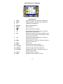
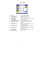
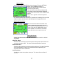
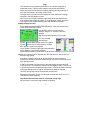
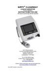
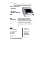
DOC 0938c
NIPPY junior+ Quick Reference Guide
Nippy jnr+ may be used with: Tracheotomy
ET Tube
Full Face Mask
Nasal Mask / Nasal Pillows
Modes
CPAP
(Continuous Positive Airway Pressure)
Pressure Support
Spontaneous breathing supported by the
ventilator. Back up in the absence of trigger.
Pressure Control
Timed inspiratory breath initiated by inspiratory
trigger. Back up in the absence of trigger.
IPPV
Timed inspiratory breath initiated by inspiratory
trigger. No EPAP. Back up in the absence of
trigger.
Alarms
Power Fail
Apnoea Alarm
Low Internal Battery
Max Breath Rate
Low External Battery
Breathing Circuit
Malfunction
Low Pressure
High Pressure
Breathing Circuit
Disconnect
High Flow alarm
Low Flow alarm
Fault
These alarms may be muted for approximately 2 minutes.
Low Internal Alarm/Memory Battery
EXPLANATION OF CONTROLS
1
14
2
13
3
12
4
11
5
10
6
17
16
15
7
9
8
1.
2.
3.
4.
5.
IPAP
EPAP
Ti
Back up
Mode
-
6.
7.
◄-
-
8.
Set
-
9.
+►
-
10. Mute
-
11.
12.
13.
14.
15.
-
Menu
Help
Lo Alarm
Hi Alarm
Ext. Batt
16. Power
17. Start
-
Fascia Buttons
Inspiratory Positive Airway Pressure adjustment
Expiratory Positive Airway Pressure adjustment
Inspiratory time adjustment
Back-up Rate adjustment
Mode selection
Starts and Stops the ventilator
Decreases the selected parameter or moves the
selection bar down the menu.
Selects the current menu function displayed by the
selection bar. OR double press for battery run time
and hours till next service.
Increases the selected parameter or moves the
selection bar up the menu
Silences alarms for 2 minutes. Press and hold for 2
seconds to cancel mute.
Menu screen
Context sensitive help messages.
Selects the Low Flow Alarm adjustment.
Selects the High Flow Alarm adjustment.
Indicates that ventilator is running on internal or
external battery power.
External power is connected.
Indicates that the ventilator is running.
2
Fascia Display
3
2
4
8
4
9
4
5
6
7
1
12
1.
2.
3.
4.
5.
6.
7.
Mode
Pressure Display
Rate Display
Volume Display
Flow Display
Settings locked symbol
Alarm Muted symbol
-
8.
I Trigger indicator
-
9.
E trigger indicator
-
10. External battery
-
11. Internal battery
12. Service Reminder
-
11
10
Current mode of ventilation.
Indicates airway pressure
Indicates patient breath rate
Indicates estimated inspiratory tidal volume
Indicates airway flow
Shows that the settings are locked.
Audible alarm has been temporarily
silenced.
“Flashes” each time the inspiratory cycle is
initiated by the patient.
“Flashes” each time the expiratory cycle is
initiated by the patient.
Indicates external battery state of charge,
when connected.
Indicates internal battery state of charge
Major service due
3
Getting Started
To Switch On
Press the Start/Stop button.
To Switch Off
Press the Start/Stop button. The “Switch Ventilator Off” message will appear
onscreen. Press the Start/Stop button again after 2 seconds. There must be a
delay of 2 seconds before each push, to prevent accidental operation.
How to adjust the Nippy jnr+
Select the desired parameter with the relevant button.
The reading adjacent to the button will be highlighted by a purple flashing box.
Alter it with the ◄- or +► buttons.
When you have finished, move on to the next adjustment or wait a couple of
seconds for the flashing box to disappear.
How to use the on-screen menu
Press the MENU button. The menu window will be displayed in front of the
main screen.
Move the selection bar up or down the menu with the ◄- or +► buttons to
highlight the desired function and press the SET button.
Follow the on-screen instruction at the bottom of the window
Press MENU at any time to exit and return to the main screen.
How to use the On-screen Help
Press the HELP button at any time for a list of help topics. Follow the simple
on-screen instructions.
Press HELP again to exit.
If during setting up, you require a description of a particular parameter, select it
then press HELP. Press HELP again to clear.
Using Help with settings locked.
When the settings have been locked, help is limited to a list of more common
problems that may arise during use and advice on how to deal with them.
SETTING UP THE NIPPY jnr+
Refer to the user manual for detailed set up instructions
4
Setting Up the Alarms
The high and low flow alarms may be set automatically. It is vital that the
alarms are tested after setting up.
Low Flow Alarm
• Allow the ventilator to cycle through several breaths before auto
setting the alarm
• Press and hold the Low Flow Alarm button
• This setting may be further adjusted manually if required.
• Test the alarm as detailed in “Alarm Conditions and Tests”
section of the user manual.
High Flow Alarm
• Allow the ventilator to cycle through several breaths before auto
setting the alarm
• Press and hold the High Flow Alarm button
• This setting may be further adjusted manually if required.
• Test the alarm as detailed in “Alarm Conditions and Tests”
section of the user manual.
Warning!
The auto set facility is not infallible. Varying leak can cause errors.
The settings must be verified and the alarm function tested. If the alarm
settings are not correct or the alarms do not operate when tested, proceed to
the manual set up.
Manual Setting
Refer to user manual for detailed alarm settings
Disconnection Alarm
The disconnection alarm acts as a back up to the high flow alarm. There are
three different sensitivity levels or it may be disabled if not required.
High Sensitivity – Useful for very restrictive
breathing circuits or small tracheotomy tubes.
Standard Sensitivity – Default level. Used for
almost all patients.
Low Sensitivity – Useful where mask leaks
cause nuisance disconnect alarms. Verify
that patient is properly ventilated during these
periods before using the Low setting.
Disabled – Disconnect alarm is switched off. Useful where mouth breathing or
excessive leak causes nuisance disconnect alarms. Verify that patient is
properly ventilated during these periods before using this setting.
Disconnection alarm relies solely on the High Flow alarm.
5
Apnoea Alarm
Select USER PREFERENCES from the main menu. From the OPTIONS
MENU, select APNOEA ALARM. To
activate the apnoea alarm, select ON and
select the required delay.
The total number of apnoeas during the last
seven days or since reset, will be displayed
along with the time duration of the longest single
apnoea.
Press + and – together to reset the apnoea
count.
An apnoea is defined as a cessation of spontaneous breathing for the set time
delay. Ventilation will continue at the backup rate during apnoea events.
Max Breath Rate Alarm
The max rate alarm will be activated if the
patients breath rate exceeds the set level.
Select USER PREFERENCES from the main
menu. From the OPTIONS MENU, select
RATE ALARM. To activate the rate alarm,
select ON and set the required max rate.
Testing the Alarms
Always test the alarms before use. Refer to the user manual for detailed
information.
High Flow Alarm
Disconnect the breathing circuit at the patient outlet port and allow the flow to
exceed the set alarm value. The alarm will be activated after 5 seconds.
Disconnect Alarm
Disconnect the breathing circuit at the patient outlet port. The High Flow alarm
will be activated after a delay of 5 seconds and will be replaced by the
disconnect alarm after 10 seconds.
Low Flow Alarm
Occlude the outlet at the patient outlet port. The alarm will sound after 10
seconds.
6
Sigh.
The ventilator can be programmed to deliver an occasional sigh with a
larger tidal volume. This prevents collapse of the alveoli (atelectasis)
which can result from the patient constantly inspiring the same volume of
gas. Sigh is available in all modes except CPAP.
The Sigh function provides a timed inspiration at the IPAP and TI settings
specified in the Sigh Settings screen.
Sigh may be set for cyclic operation, sigh breath at the specified interval
or an external switch (Manual mode). Or a combination of both, where the
cyclic sigh may be supplemented by extra sigh breaths on demand.
Setting the Sigh function
Press MENU and select USER PREFERENCES. In the User preferences
screen select SIGH SETTINGS.
Use the SET button to scroll down the
settings, using the +/- buttons to alter the
settings.
Sigh Interval sets frequency of cyclic sigh
Ext Trig = manual
switched sigh
Symbol S shows Manual Sigh function is enabled.
Symbol Sc shows Cyclic Sigh function is enabled.
Blue Symbol = Sigh mode enabled.
Green Symbol = External sigh trigger acknowledged.
Purple Symbol = Sigh breath activated.
Sigh breath pressure (S) is indicated on the pressure bargraph display.
Đ
m
Đ
Note: If the ventilator IPAP is adjusted after the sigh has been set up, this may
affect the sigh setting.
If the IPAP is reduced the sigh will be reduced by the same amount, to
maintain the difference between IPAP and Sigh. This can be overridden in the
Sigh Settings screen.
If IPAP is increased to a value equal to the sigh setting, the sigh value will
“track” the IPAP. This effectively makes IPAP and Sigh the same. This is done
to prevent accidental increase of the sigh breath. The sigh will need to be reset
in the Sigh Settings screen. Sigh is cancelled when Mode is changed.
The IPAP during Sigh cannot be lower than normal IPAP.
Regardless of the back up rate, a sigh breath is timed with an IE ratio of 1:2.
This does not affect triggering.
High flow and disconnect alarm is suspended during Sigh.
No more than 5 consecutive sigh breaths are allowed.
7
Running the Nippy jnr+ on Battery Power
Refer to user manual for detailed description / instructions.
When connected to mains, the ventilator will recharge its own internal
and/or external battery. Leave connected to the mains supply in between
periods of use to keep the batteries charged or to recharge ready for the
next use or to recover a deeply discharged battery.
The ventilator will select its power source, in the following sequence:1. – Mains Electricity
2. - External Battery (if connected)
3. – Internal Battery (if fitted)
Battery icons
The battery icons on the main screen indicate a number of things relating
to the batteries:INT icon shows that an internal battery is fitted. INT will flash when
running on internal battery. The green bottom section indicates the
amount of charge remaining. A flashing yellow top section indicates that
the external battery is charging.
EXT icon shows that the recommended external battery is connected.
EXT will flash when running on external battery. The green bottom
section indicates the amount of charge remaining. A flashing yellow top
section indicates that the external battery is charging.
EXT icon with a black fill shows that an alternative external battery is
connected. The state of charge cannot be displayed. The ventilator
cannot charge this type of battery.
Run Time Indication
To check remaining run time, double press
the SET button whilst running on battery
power. The screen will show an estimate of
running time based on the current state of
charge and settings.
Low Battery Alarm
When the battery is depleted an alarm will sound, accompanied by an on
screen message, “Battery Power Running Low”
When battery power reaches a critical level, the alarm will change to a
continuous tone and the on-screen message will change to “Battery
Power Exhausted. About to switch off. Connect to Mains Power Now”
After auto power off, the alarm will continue until the Mute is pressed.
8