1
SIP Phone
<KX-UT136>
Model No.
KX-UT113/KX-UT123
KX-UT133/KX-UT136
Thank you for purchasing this Panasonic product.
Please read this manual carefully before using this product and save this manual for future use.
KX-UT113/KX-UT123/KX-UT133/KX-UT136: Software File Version 01.000 or later
In this manual, the suffix of each model number is omitted unless necessary.
Document Version: 2011-06
Introduction
Introduction
Outline
This Administrator Guide provides detailed information on the configuration and management of this unit.
Audience
This Administrator Guide contains explanations about the installation, maintenance, and management of the
unit and is aimed at network administrators and phone system dealers.
Technical descriptions are included in this guide. Prior knowledge of networking and VoIP (Voice over Internet
Protocol) is required.
Related Documentation
Getting Started
Briefly describes basic information about the installation of the unit.
Operating Instructions
Describes information about the installation and operation of the unit.
Manuals and supporting information are provided on the Panasonic Web site at:
http://www.panasonic.com/sip (for users in the United States)
http://panasonic.net/pcc/support/sipphone (for users in all other countries/areas)
Technical Support
When technical support is required, contact your phone system dealer.
Open Source Software Notice
Parts of this product use open source software. For details about the open source software, see the Operating
Instructions.
Trademarks
•
•
•
•
Microsoft, Excel, Internet Explorer, Outlook, and Windows are either registered trademarks or trademarks
of Microsoft Corporation in the United States and/or other countries.
Linux is a registered trademark of Linus Torvalds in the United States, other countries, or both.
All other trademarks identified herein are the property of their respective owners.
Microsoft product screen shot(s) reprinted with permission from Microsoft Corporation.
NOTES
•
2
The screen shots shown in this guide are provided for reference only, and may differ from the screens
displayed on your PC.
Administrator Guide
Document Version
www.InternetVoipPhone.co.uk | [email protected] | 0800 088 4846
2011-06
Table of Contents
Table of Contents
1 Initial Setup .............................................................................................15
1.1
Setup ................................................................................................................................16
1.1.1
Factory Defaults .............................................................................................................16
1.1.2
Language Selection for the Unit .....................................................................................16
1.1.3
Basic Network Setup ......................................................................................................16
1.1.4
Overview of Programming ..............................................................................................18
1.1.5
Phone User Interface Programming ...............................................................................18
1.1.5.1
Changing the Language for Phone User Interface Programming ...............................19
1.1.6
Web User Interface Programming ..................................................................................19
1.1.6.1
Password for Web User Interface Programming .........................................................19
1.1.6.2
Changing the Language for Web User Interface Programming ..................................20
1.1.6.3
Before Accessing the Web User Interface ...................................................................20
1.1.6.4
Accessing the Web User Interface ..............................................................................22
1.1.7
Other Network Settings ..................................................................................................26
1.1.7.1
Firewall and Router Setup ...........................................................................................26
1.1.7.2
NAT (Network Address Translation) Setup .................................................................27
1.1.7.3
Global Address Detection ............................................................................................28
1.2
Reset and Firmware Update ...........................................................................................29
1.2.1
Reset ..............................................................................................................................29
1.2.1.1
Resetting to Factory Default (Factory Setting) ............................................................29
1.2.1.2
Resetting the Network Settings (IP Reset) ..................................................................29
1.2.1.3
Resetting the Settings Made through the Web User Interface (Reset Web
Settings) ......................................................................................................................30
1.2.2
Firmware Update ............................................................................................................30
2 General Information on Provisioning ...................................................31
2.1
2.1.1
2.1.2
2.1.3
2.1.4
2.2
2.2.1
2.2.2
2.2.3
2.2.4
2.2.5
2.2.6
2.3
2.4
2.5
2.5.1
2.5.2
Pre-provisioning ..............................................................................................................32
What is Pre-provisioning? ..............................................................................................32
Pre-provisioning when Setting Static IP Addresses .......................................................33
Server for Pre-provisioning .............................................................................................33
Pre-provisioning Setting Example ..................................................................................33
Provisioning ....................................................................................................................36
What is Provisioning? .....................................................................................................36
Protocols for Provisioning ...............................................................................................36
Configuration File ...........................................................................................................36
Downloading Configuration Files ....................................................................................38
Provisioning Server Setting Example .............................................................................44
Encryption ......................................................................................................................45
Priority of Setting Methods ............................................................................................46
Configuration File Specifications ..................................................................................47
Configuration File Examples ..........................................................................................48
Examples of Codec Settings ..........................................................................................48
Example with Incorrect Descriptions ..............................................................................49
3 Phone User Interface Programming .....................................................51
3.1
3.1.1
3.1.2
3.1.3
3.1.4
Phone User Interface Programming ..............................................................................52
Phone User Interface Feature List and Direct Commands .............................................52
Phonebook deletion ........................................................................................................52
Terminal Number Settings ..............................................................................................52
Reset Web ID/Password ................................................................................................52
4 Web User Interface Programming ........................................................55
Document Version
2011-06
Administrator Guide
www.InternetVoipPhone.co.uk | [email protected] | 0800 088 4846
3
Table of Contents
4.1
Web User Interface Setting List .....................................................................................56
4.2
Status ...............................................................................................................................65
4.2.1
Version Information ........................................................................................................65
4.2.1.1
Version Information .....................................................................................................66
Model ........................................................................................................................66
Operating Bank .........................................................................................................66
IPL Version ...............................................................................................................66
Firmware Version ......................................................................................................66
4.2.2
Network Status ...............................................................................................................66
4.2.2.1
Network Status ............................................................................................................67
MAC Address ............................................................................................................67
Ethernet Link Status (LAN Port) ................................................................................67
Ethernet Link Status (PC Port) (KX-UT123/KX-UT133/KX-UT136 only) ..................67
Connection Mode ......................................................................................................67
IP Address ................................................................................................................68
Subnet Mask .............................................................................................................68
Default Gateway .......................................................................................................68
DNS1 ........................................................................................................................68
DNS2 ........................................................................................................................69
4.2.3
VoIP Status ....................................................................................................................69
4.2.3.1
VoIP Status ..................................................................................................................69
Line No. .....................................................................................................................69
Phone Number ..........................................................................................................70
VoIP Status ...............................................................................................................70
4.3
Network ............................................................................................................................70
4.3.1
Basic Network Settings ..................................................................................................70
4.3.1.1
Connection Mode ........................................................................................................71
Connection Mode ......................................................................................................71
4.3.1.2
DHCP Settings ............................................................................................................71
Host Name ................................................................................................................71
Domain Name Server ...............................................................................................72
4.3.1.3
Static Settings ..............................................................................................................72
Static IP Address ......................................................................................................72
Subnet Mask .............................................................................................................73
Default Gateway .......................................................................................................73
DNS1 ........................................................................................................................73
DNS2 ........................................................................................................................74
4.3.2
Ethernet Port Settings ....................................................................................................74
4.3.2.1
Link Speed/Duplex Mode ............................................................................................75
LAN Port ...................................................................................................................75
PC Port (KX-UT123/KX-UT133/KX-UT136 only) ......................................................75
4.3.2.2
VLAN Settings .............................................................................................................75
Enable VLAN ............................................................................................................75
IP Phone (VLAN ID) ..................................................................................................75
IP Phone (Priority) .....................................................................................................76
PC (VLAN ID) (KX-UT123/KX-UT133/KX-UT136 only) ............................................76
PC (Priority) (KX-UT123/KX-UT133/KX-UT136 only) ...............................................76
4.3.3
HTTP Client Settings ......................................................................................................76
4.3.3.1
HTTP Client Settings ...................................................................................................77
HTTP Version ...........................................................................................................77
HTTP User Agent ......................................................................................................77
4.3.3.2
HTTP Authentication ...................................................................................................77
Authentication ID .......................................................................................................77
Authentication Password ..........................................................................................78
4.3.3.3
Proxy Server Settings ..................................................................................................78
4
Administrator Guide
Document Version
www.InternetVoipPhone.co.uk | [email protected] | 0800 088 4846
2011-06
Table of Contents
4.3.4
4.3.4.1
4.3.4.2
4.3.5
4.3.5.1
4.3.5.2
4.3.5.3
4.4
4.4.1
4.4.1.1
4.4.2
4.4.2.1
4.4.3
4.4.3.1
4.4.4
4.4.4.1
4.4.5
4.4.5.1
4.4.5.2
4.4.5.3
4.4.5.4
4.4.5.5
4.4.5.6
4.5
Enable Proxy .............................................................................................................78
Proxy Server Address ...............................................................................................78
Proxy Server Port ......................................................................................................78
Global Address Detection ...............................................................................................78
Global Address Detection ............................................................................................79
Detection Method ......................................................................................................79
Detection Interval ......................................................................................................79
STUN Server ...............................................................................................................79
STUN Server Address ..............................................................................................79
STUN Server Port .....................................................................................................80
Static NAPT Settings ......................................................................................................80
Global IP Address ........................................................................................................80
Global IP Address .....................................................................................................80
Enable Global IP Address Usage per Line ..................................................................81
Line 1–Line 4 ............................................................................................................81
External RTP Port ........................................................................................................81
Channel 1–25 ...........................................................................................................81
System .............................................................................................................................82
Web Language ...............................................................................................................82
Web Language ............................................................................................................82
Language ..................................................................................................................82
Administrator Password .................................................................................................82
Change Administrator Password .................................................................................83
Current Password .....................................................................................................83
New Password ..........................................................................................................83
Confirm New Password ............................................................................................83
Change User Password .................................................................................................84
Change User Password ...............................................................................................84
Current Password .....................................................................................................84
New Password ..........................................................................................................84
Confirm New Password ............................................................................................85
Web Server Settings ......................................................................................................85
Web Server Settings ....................................................................................................85
Web Server Port .......................................................................................................85
Port Close Timer .......................................................................................................86
Time Adjust Settings ......................................................................................................86
Synchronization ...........................................................................................................87
Enable Synchronization by NTP ...............................................................................87
Synchronization Interval ............................................................................................87
Time Server .................................................................................................................87
NTP Server Address .................................................................................................87
Time Zone ...................................................................................................................87
Time Zone .................................................................................................................87
Daylight Saving Time (Summer Time) .........................................................................88
Enable DST (Enable Summer Time) ........................................................................88
DST Offset (Summer Time Offset) ............................................................................88
Start Day and Time of DST (Start Day and Time of Summer Time) ...........................88
Month ........................................................................................................................88
Day of Week .............................................................................................................88
Time ..........................................................................................................................89
End Day and Time of DST (End Day and Time of Summer Time) ..............................89
Month ........................................................................................................................89
Day of Week .............................................................................................................90
Time ..........................................................................................................................91
VoIP ..................................................................................................................................91
Document Version
2011-06
Administrator Guide
www.InternetVoipPhone.co.uk | [email protected] | 0800 088 4846
5
Table of Contents
4.5.1
4.5.1.1
4.5.2
4.5.2.1
4.5.2.2
4.5.2.3
4.5.2.4
4.5.2.5
4.5.2.6
4.5.2.7
4.5.2.8
4.5.2.9
4.5.2.10
4.5.2.11
4.5.2.12
4.5.2.13
4.5.3
4.5.3.1
4.5.4
6
SIP Settings ....................................................................................................................91
SIP Setting ...................................................................................................................91
SIP User Agent .........................................................................................................91
SIP Settings [Line 1]–[Line 4] .........................................................................................92
Phone Number ............................................................................................................93
Phone Number ..........................................................................................................93
SIP URI .....................................................................................................................93
SIP Server ...................................................................................................................93
Registrar Server Address ..........................................................................................93
Registrar Server Port ................................................................................................93
Proxy Server Address ...............................................................................................94
Proxy Server Port ......................................................................................................94
Presence Server Address .........................................................................................94
Presence Server Port ................................................................................................94
Outbound Proxy Server ...............................................................................................95
Outbound Proxy Server Address ..............................................................................95
Outbound Proxy Server Port .....................................................................................95
SIP Service Domain ....................................................................................................95
Service Domain .........................................................................................................95
SIP Source Port ...........................................................................................................95
Source Port ...............................................................................................................95
SIP Authentication .......................................................................................................96
Authentication ID .......................................................................................................96
Authentication Password ..........................................................................................96
DNS .............................................................................................................................96
Enable DNS SRV lookup ..........................................................................................96
SRV lookup Prefix for UDP .......................................................................................97
SRV lookup Prefix for TCP .......................................................................................97
Transport Protocol of SIP ............................................................................................97
Transport Protocol ....................................................................................................97
Timer Settings .............................................................................................................98
T1 Timer ....................................................................................................................98
T2 Timer ....................................................................................................................98
Timer B .....................................................................................................................98
Timer D .....................................................................................................................99
Timer F ......................................................................................................................99
Timer H .....................................................................................................................99
Timer J ......................................................................................................................99
Quality of Service (QoS) ..............................................................................................99
SIP Packet QoS (DSCP) ...........................................................................................99
SIP extensions ...........................................................................................................100
Supports 100rel (RFC 3262) ...................................................................................100
Supports Session Timer (RFC 4028) ......................................................................100
NAT Identity ...............................................................................................................100
Keep Alive Interval ..................................................................................................100
Supports Rport (RFC 3581) ....................................................................................101
Security ......................................................................................................................101
Enable SSAF (SIP Source Address Filter) .............................................................101
VoIP Settings ................................................................................................................101
RTP Settings .............................................................................................................102
RTP Packet Time ....................................................................................................102
Minimum RTP Port Number ....................................................................................102
Maximum RTP Port Number ...................................................................................102
Telephone-event Payload Type ..............................................................................103
VoIP Settings [Line 1]–[Line 4] .....................................................................................104
Administrator Guide
Document Version
www.InternetVoipPhone.co.uk | [email protected] | 0800 088 4846
2011-06
Table of Contents
4.5.4.1
4.5.4.2
4.5.4.3
4.5.4.4
4.5.4.5
4.5.4.6
4.6
4.6.1
4.6.1.1
4.6.1.2
4.6.2
4.6.2.1
4.6.2.2
4.6.2.3
4.6.2.4
Quality of Service (QoS) ............................................................................................104
RTP Packet QoS (DSCP) .......................................................................................104
Statistical Information ................................................................................................104
RTCP Enable ..........................................................................................................104
RTCP Interval .........................................................................................................105
Jitter Buffer ................................................................................................................105
Maximum Delay ......................................................................................................105
Minimum Delay .......................................................................................................105
Initial Delay .............................................................................................................105
DTMF .........................................................................................................................106
DTMF Type .............................................................................................................106
Call Hold ....................................................................................................................106
Supports RFC 2543 (c=0.0.0.0) ..............................................................................106
CODEC Preferences .................................................................................................107
G722 (Enable) .........................................................................................................107
G722 (Priority) .........................................................................................................107
PCMA (Enable) .......................................................................................................107
PCMA (Priority) .......................................................................................................107
G726–32 (Enable) ..................................................................................................107
G726–32 (Priority) ...................................................................................................108
G729A (Enable) ......................................................................................................108
G729A (Priority) ......................................................................................................108
PCMU (Enable) .......................................................................................................108
PCMU (Priority) .......................................................................................................108
Telephone ......................................................................................................................109
Call Control ...................................................................................................................109
Call Control ................................................................................................................109
Send SUBSCRIBE to Voice Mail Server ................................................................109
Conference Server URI ...........................................................................................110
Inter-digit Timeout ...................................................................................................110
Timer for Dial Plan ..................................................................................................110
International Call Prefix ...........................................................................................110
Country Calling Code ..............................................................................................111
National Access Code .............................................................................................111
Default Line for Outgoing ........................................................................................111
Flash/Recall Button .................................................................................................111
Flash Hook Event ....................................................................................................112
Direct Call Pickup ....................................................................................................112
Call Rejection Phone Numbers .................................................................................112
1–30 ........................................................................................................................112
Call Control [Line 1]–[Line 4] ........................................................................................112
Call Control ................................................................................................................113
Display Name ..........................................................................................................113
Voice Mail Access Number .....................................................................................113
Enable Shared Call .................................................................................................114
Synchronize Do Not Disturb and Call Forward .......................................................114
Resource List URI ...................................................................................................115
Dial Plan ....................................................................................................................115
Dial Plan (max 500 columns) ..................................................................................115
Call Even If Dial Plan Does Not Match ...................................................................115
Call Features .............................................................................................................116
Block Caller ID ........................................................................................................116
Block Anonymous Call ............................................................................................116
Do Not Disturb ........................................................................................................117
Call Forward ..............................................................................................................117
Document Version
2011-06
Administrator Guide
www.InternetVoipPhone.co.uk | [email protected] | 0800 088 4846
7
Table of Contents
4.6.3
4.6.3.1
4.6.4
4.6.4.1
4.6.4.2
4.6.4.3
4.6.4.4
4.6.4.5
4.6.5
4.6.5.1
4.6.6
4.6.6.1
4.6.7
4.7
4.7.1
4.7.1.1
4.7.2
4.7.2.1
4.7.3
4.7.3.1
8
Unconditional (Enable Call Forward) ......................................................................117
Unconditional (Phone Number) ..............................................................................118
Busy (Enable Call Forward) ....................................................................................118
Busy (Phone Number) ............................................................................................119
No Answer (Enable Call Forward) ..........................................................................119
No Answer (Phone Number) ...................................................................................120
No Answer (Ring Count) .........................................................................................120
Flexible Button Settings (KX-UT133/KX-UT136 only) ..................................................121
Flexible Button Settings .............................................................................................121
Type (No. 1–24) ......................................................................................................121
Parameter (No. 1–24) .............................................................................................121
Label Name (No. 1–24) ..........................................................................................122
Tone Settings ...............................................................................................................122
Dial Tone ...................................................................................................................122
Tone Frequencies ...................................................................................................122
Tone Timings ..........................................................................................................123
Busy Tone .................................................................................................................123
Tone Frequencies ...................................................................................................123
Tone Timings ..........................................................................................................123
Ringing Tone .............................................................................................................124
Tone Frequencies ...................................................................................................124
Tone Timings ..........................................................................................................124
Stutter Tone ...............................................................................................................124
Tone Frequencies ...................................................................................................124
Tone Timings ..........................................................................................................124
Reorder Tone ............................................................................................................125
Tone Frequencies ...................................................................................................125
Tone Timings ..........................................................................................................125
Telephone Settings ......................................................................................................125
Telephone Settings ....................................................................................................126
Key Click Tone ........................................................................................................126
Extension PIN .........................................................................................................126
Number Matching Lower Digit .................................................................................126
Number Matching Upper Digit .................................................................................126
Import Phonebook ........................................................................................................127
Import Phonebook .....................................................................................................127
File Name ................................................................................................................127
Export Phonebook ........................................................................................................127
Maintenance ..................................................................................................................128
Firmware Maintenance .................................................................................................128
Firmware Maintenance ..............................................................................................129
Enable Firmware Update ........................................................................................129
Update Type ...........................................................................................................129
Firmware File URL ..................................................................................................129
Local Firmware Update ................................................................................................130
Local Firmware Update .............................................................................................130
Encryption ...............................................................................................................130
File Name ................................................................................................................130
Provisioning Maintenance ............................................................................................130
Provisioning Maintenance .........................................................................................131
Enable Provisioning ................................................................................................131
Standard File URL ..................................................................................................131
Product File URL .....................................................................................................132
Master File URL ......................................................................................................132
Cyclic Auto Resync .................................................................................................132
Administrator Guide
Document Version
www.InternetVoipPhone.co.uk | [email protected] | 0800 088 4846
2011-06
Table of Contents
4.7.4
4.7.4.1
4.7.4.2
4.7.5
4.7.6
Resync Interval .......................................................................................................133
Header Value for Resync Event .............................................................................133
Management Server .....................................................................................................133
Management Server ..................................................................................................133
Management Server URL .......................................................................................133
Management Server Authentication ..........................................................................134
Authentication ID .....................................................................................................134
Authentication Password ........................................................................................134
Reset to Defaults ..........................................................................................................134
Restart ..........................................................................................................................135
5 Configuration File Programming ........................................................137
5.1
5.2
5.2.1
5.2.2
5.3
5.3.1
5.3.2
5.3.3
5.3.4
5.3.5
Configuration File Parameter List ...............................................................................138
General Information on the Configuration Files ........................................................147
Configuration File Parameters ......................................................................................147
Characters Available for String Values .........................................................................148
System Settings ............................................................................................................149
Login Account Settings .................................................................................................149
ADMIN_ID .................................................................................................................149
ADMIN_PASS ...........................................................................................................149
USER_ID ...................................................................................................................149
USER_PASS .............................................................................................................149
System Time Settings ..................................................................................................150
TIME_ZONE ..............................................................................................................150
DST_ENABLE ...........................................................................................................150
DST_OFFSET ...........................................................................................................151
DST_START_MONTH ...............................................................................................151
DST_START_ORDINAL_DAY ..................................................................................151
DST_START_DAY_OF_WEEK .................................................................................152
DST_START_TIME ...................................................................................................152
DST_STOP_MONTH ................................................................................................153
DST_STOP_ORDINAL_DAY ....................................................................................153
DST_STOP_DAY_OF_WEEK ...................................................................................153
DST_STOP_TIME .....................................................................................................154
LOCAL_TIME_ZONE_POSIX ...................................................................................154
Syslog Settings .............................................................................................................155
SYSLOG_EVENT_SIP ..............................................................................................155
SYSLOG_EVENT_CFG ............................................................................................155
SYSLOG_EVENT_VOIP ...........................................................................................156
SYSLOG_EVENT_TEL .............................................................................................156
SYSLOG_ADDR ........................................................................................................156
SYSLOG_PORT ........................................................................................................156
SYSLOG_RTPSMLY_INTVL_n .................................................................................157
Firmware Update Settings ............................................................................................157
FIRM_UPGRADE_ENABLE ......................................................................................157
FIRM_VERSION ........................................................................................................157
FIRM_UPGRADE_AUTO ..........................................................................................158
FIRM_FILE_PATH .....................................................................................................158
Provisioning Settings ....................................................................................................159
OPTION66_ENABLE .................................................................................................159
OPTION66_REBOOT ................................................................................................159
PROVISION_ENABLE ..............................................................................................159
CFG_STANDARD_FILE_PATH ................................................................................160
CFG_PRODUCT_FILE_PATH ..................................................................................160
CFG_MASTER_FILE_PATH .....................................................................................161
Document Version
2011-06
Administrator Guide
www.InternetVoipPhone.co.uk | [email protected] | 0800 088 4846
9
Table of Contents
5.3.6
5.4
5.4.1
5.4.2
5.4.3
5.4.4
5.4.5
5.4.6
10
CFG_FILE_KEY1 ......................................................................................................162
CFG_FILE_KEY2 ......................................................................................................163
CFG_FILE_KEY3 ......................................................................................................163
CFG_FILE_KEY_LENGTH ........................................................................................163
CFG_CYCLIC ............................................................................................................163
CFG_CYCLIC_INTVL ................................................................................................164
CFG_RTRY_INTVL ...................................................................................................164
CFG_RESYNC_TIME ...............................................................................................164
CFG_RESYNC_FROM_SIP ......................................................................................165
Management Server Settings .......................................................................................165
ACS_URL ..................................................................................................................165
ACS_USER_ID ..........................................................................................................165
ACS_PASS ................................................................................................................166
PERIODIC_INFORM_ENABLE .................................................................................166
PERIODIC_INFORM_INTERVAL .............................................................................166
PERIODIC_INFORM_TIME .......................................................................................166
CON_REQ_USER_ID ...............................................................................................167
CON_REQ_PASS .....................................................................................................167
Network Settings ...........................................................................................................168
IP Settings ....................................................................................................................168
CONNECTION_TYPE ...............................................................................................168
HOST_NAME ............................................................................................................168
DHCP_DNS_ENABLE ...............................................................................................168
STATIC_IP_ADDRESS .............................................................................................169
STATIC_SUBNET .....................................................................................................169
STATIC_GATEWAY ..................................................................................................170
USER_DNS1_ADDR .................................................................................................170
USER_DNS2_ADDR .................................................................................................170
DNS Settings ................................................................................................................171
DNS_QRY_PRLL ......................................................................................................171
DNS_PRIORITY ........................................................................................................171
DNS1_ADDR .............................................................................................................172
DNS2_ADDR .............................................................................................................172
Ethernet Port Settings ..................................................................................................172
VLAN_ENABLE .........................................................................................................172
VLAN_ID_IP_PHONE ...............................................................................................172
VLAN_PRI_IP_PHONE .............................................................................................173
VLAN_ID_PC .............................................................................................................173
VLAN_PRI_PC ..........................................................................................................173
HTTP Settings ..............................................................................................................174
HTTPD_PORTOPEN_AUTO ....................................................................................174
HTTP_VER ................................................................................................................174
HTTP_USER_AGENT ...............................................................................................174
HTTP_SSL_VERIFY .................................................................................................175
CFG_ROOT_CERTIFICATE_PATH ..........................................................................175
Time Adjust Settings ....................................................................................................176
NTP_ADDR ...............................................................................................................176
NTP_PORT ...............................................................................................................176
TIME_SYNC_INTVL ..................................................................................................176
TIME_QUERY_INTVL ...............................................................................................177
STUN Settings ..............................................................................................................177
STUN_SERV_ADDR .................................................................................................177
STUN_SERV_PORT .................................................................................................177
STUN_2NDSERV_ADDR ..........................................................................................177
STUN_2NDSERV_PORT ..........................................................................................178
Administrator Guide
Document Version
www.InternetVoipPhone.co.uk | [email protected] | 0800 088 4846
2011-06
Table of Contents
5.4.7
5.5
5.5.1
5.5.2
Miscellaneous Network Settings ..................................................................................178
NW_SETTING_ENABLE ...........................................................................................178
CUSTOM_WEB_PAGE .............................................................................................178
Telephone Settings .......................................................................................................179
Call Control Settings .....................................................................................................179
VM_SUBSCRIBE_ENABLE ......................................................................................179
CONFERENCE_SERVER_URI ................................................................................179
FIRSTDIGIT_TIM .......................................................................................................179
INTDIGIT_TIM ...........................................................................................................180
MACRODIGIT_TIM ....................................................................................................180
INTERNATIONAL_ACCESS_CODE .........................................................................180
COUNTRY_CALLING_CODE ...................................................................................180
NATIONAL_ACCESS_CODE ...................................................................................181
DEFAULT_LINE_SELECT ........................................................................................181
DATA_LINE_MODE ..................................................................................................181
NUM_PLAN_PICKUP_DIRECT ................................................................................181
TALK_PACKAGE ......................................................................................................182
HOLD_PACKAGE .....................................................................................................182
HOLD_RECALL_TIM ................................................................................................182
AUTO_ANS_RING_TIM ............................................................................................182
RINGING_OFF_SETTING_ENABLE ........................................................................183
AUTO_CALL_HOLD ..................................................................................................183
REDIALKEY_CALLLOG_ENABLE ............................................................................183
ONHOOK_TRANSFER_ENABLE .............................................................................183
DISCONNECTION_MODE ........................................................................................184
TONE_LEN_DISCONNECT_HANDSET ...................................................................184
TONE_LEN_DISCONNECT_HANDSFREE ..............................................................184
KEY_PAD_TONE ......................................................................................................184
Tone Settings ...............................................................................................................185
DIAL_TONE1_FRQ ...................................................................................................185
DIAL_TONE1_GAIN ..................................................................................................185
DIAL_TONE1_RPT ...................................................................................................185
DIAL_TONE1_TIMING ..............................................................................................185
DIAL_TONE2_FRQ ...................................................................................................186
DIAL_TONE2_GAIN ..................................................................................................186
DIAL_TONE2_RPT ...................................................................................................186
DIAL_TONE2_TIMING ..............................................................................................186
DIAL_TONE4_FRQ ...................................................................................................186
DIAL_TONE4_GAIN ..................................................................................................187
DIAL_TONE4_RPT ...................................................................................................187
DIAL_TONE4_TIMING ..............................................................................................187
BUSY_TONE_FRQ ...................................................................................................188
BUSY_TONE_GAIN ..................................................................................................188
BUSY_TONE_RPT ....................................................................................................188
BUSY_TONE_TIMING ..............................................................................................188
REORDER_TONE_FRQ ...........................................................................................189
REORDER_TONE_GAIN ..........................................................................................189
REORDER_TONE_RPT ...........................................................................................189
REORDER_TONE_TIMING ......................................................................................189
RINGBACK_TONE_FRQ ..........................................................................................190
RINGBACK_TONE_GAIN .........................................................................................190
RINGBACK_TONE_RPT ...........................................................................................190
RINGBACK_TONE_TIMING .....................................................................................190
HOLD_ALARM_FRQ .................................................................................................191
HOLD_ALARM_GAIN ...............................................................................................191
Document Version
2011-06
Administrator Guide
www.InternetVoipPhone.co.uk | [email protected] | 0800 088 4846
11
Table of Contents
5.5.3
5.5.4
5.5.5
5.6
5.6.1
5.6.2
5.6.3
12
HOLD_ALARM_RPT .................................................................................................191
HOLD_ALARM_TIMING ............................................................................................191
CW_TONE1_FRQ .....................................................................................................191
CW_TONE1_GAIN ....................................................................................................192
CW_TONE1_RPT .....................................................................................................192
CW_TONE1_TIMING ................................................................................................192
HOLD_TONE_FRQ ...................................................................................................192
HOLD_TONE_GAIN ..................................................................................................192
HOLD_TONE_RPT ...................................................................................................193
HOLD_TONE_TIMING ..............................................................................................193
BELL_CORE_PATTERN1_TIMING ..........................................................................193
BELL_CORE_PATTERN2_TIMING ..........................................................................193
BELL_CORE_PATTERN3_TIMING ..........................................................................193
BELL_CORE_PATTERN4_TIMING ..........................................................................194
BELL_CORE_PATTERN5_TIMING ..........................................................................194
Telephone Settings ......................................................................................................194
DISPLAY_NAME_REPLACE ....................................................................................194
NUMBER_MATCHING_LOWER_DIGIT ...................................................................194
NUMBER_MATCHING_UPPER_DIGIT ....................................................................195
DISPLAY_DATE_PATTERN .....................................................................................195
DISPLAY_TIME_PATTERN ......................................................................................195
DEFAULT_LANGUAGE ............................................................................................195
EXTENSION_PIN ......................................................................................................196
POUND_KEY_DELIMITER_ENABLE .......................................................................196
Miscellaneous Telephone Settings ...............................................................................197
ADJDATA_GAIN .......................................................................................................197
Flexible Button Settings (KX-UT133/KX-UT136 only) ..................................................199
FLEX_BUTTON_FACILITY_ACTx ............................................................................199
FLEX_BUTTON_FACILITY_ARGx ...........................................................................199
FLEX_BUTTON_QUICK_DIALx ................................................................................199
FLEX_BUTTON_LABELx ..........................................................................................200
VoIP Settings .................................................................................................................200
Codec Settings .............................................................................................................200
CODEC_G711_REQ .................................................................................................200
CODEC_G729_PARAM ............................................................................................200
CODEC_ENABLEx_n ................................................................................................201
CODEC_PRIORITYx_n .............................................................................................201
RTP Settings ................................................................................................................202
DSCP_RTP_n ...........................................................................................................202
RTCP_INTVL_n .........................................................................................................202
MAX_DELAY_n .........................................................................................................202
MIN_DELAY_n ..........................................................................................................203
NOM_DELAY_n ........................................................................................................203
RTP_PORT_MIN .......................................................................................................203
RTP_PORT_MAX ......................................................................................................204
RTP_PTIME ..............................................................................................................204
RTCP_ENABLE_n .....................................................................................................205
RTCP_SEND_BY_SDP_n .........................................................................................205
RTP_CLOSE_ENABLE_n .........................................................................................205
Miscellaneous VoIP Settings ........................................................................................206
OUTBANDDTMF_n ...................................................................................................206
OUTBANDDTMF_VOL ..............................................................................................206
INBANDDTMF_VOL ..................................................................................................206
TELEVENT_PAYLOAD .............................................................................................206
RFC2543_HOLD_ENABLE_n ...................................................................................207
Administrator Guide
Document Version
www.InternetVoipPhone.co.uk | [email protected] | 0800 088 4846
2011-06
Table of Contents
5.7
5.7.1
5.7.2
DTMF_SIGNAL_LEN ................................................................................................207
DTMF_INTDIGIT_TIM ...............................................................................................207
Line Settings ..................................................................................................................208
Call Control Settings .....................................................................................................208
DISPLAY_NAME_n ...................................................................................................208
VM_NUMBER_n ........................................................................................................208
DIAL_PLAN_n ...........................................................................................................208
DIAL_PLAN_NOT_MATCH_ENABLE_n ...................................................................209
SHARED_CALL_ENABLE_n ....................................................................................209
FWD_DND_SYNCHRO_ENABLE_n ........................................................................210
RESOURCELIST_URI_n ..........................................................................................210
CW_ENABLE_n ........................................................................................................211
RETURN_VOL_SET_DEFAULT_ENABLE ...............................................................211
FLASH_RECALL_TERMINATE ................................................................................211
FLASHHOOK_CONTENT_TYPE ..............................................................................211
SIP Settings ..................................................................................................................212
SIP_USER_AGENT ..................................................................................................212
PHONE_NUMBER_n ................................................................................................212
SIP_URI_n .................................................................................................................212
LINE_ENABLE_n ......................................................................................................213
PROFILE_ENABLEn .................................................................................................213
SIP_AUTHID_n .........................................................................................................214
SIP_PASS_n .............................................................................................................214
SIP_SRC_PORT_n ...................................................................................................214
SIP_PRXY_ADDR_n .................................................................................................214
SIP_PRXY_PORT_n .................................................................................................215
SIP_RGSTR_ADDR_n ..............................................................................................215
SIP_RGSTR_PORT_n ..............................................................................................215
SIP_SVCDOMAIN_n .................................................................................................215
REG_EXPIRE_TIME_n .............................................................................................216
REG_INTERVAL_RATE_n ........................................................................................216
SIP_SESSION_TIME_n ............................................................................................216
SIP_SESSION_METHOD_n .....................................................................................217
DSCP_SIP_n .............................................................................................................217
SIP_2NDPROXY_ADDR_n .......................................................................................217
SIP_2NDPROXY_PORT_n .......................................................................................217
SIP_2NDRGSTR_ADDR_n .......................................................................................218
SIP_2NDRGSTR_PORT_n .......................................................................................218
SIP_TIMER_T1_n .....................................................................................................218
SIP_TIMER_T2_n .....................................................................................................219
SIP_TIMER_T4_n .....................................................................................................219
SIP_FOVR_NORSP_n ..............................................................................................219
SIP_FOVR_MAX_n ...................................................................................................220
SIP_REFRESHER_n .................................................................................................220
SIP_DNSSRV_ENA_n ..............................................................................................220
SIP_UDP_SRV_PREFIX_n .......................................................................................221
SIP_TCP_SRV_PREFIX_n .......................................................................................221
SIP_100REL_ENABLE_n ..........................................................................................222
SIP_INVITE_EXPIRE_n ............................................................................................222
SIP_18X_RTX_INTVL_n ...........................................................................................222
SIP_PRSNC_ADDR_n ..............................................................................................223
SIP_PRSNC_PORT_n ..............................................................................................223
SIP_2NDPRSNC_ADDR_n .......................................................................................223
SIP_2NDPRSNC_PORT_n .......................................................................................223
USE_DEL_REG_OPEN_n ........................................................................................224
Document Version
2011-06
Administrator Guide
www.InternetVoipPhone.co.uk | [email protected] | 0800 088 4846
13
Table of Contents
USE_DEL_REG_CLOSE_n ......................................................................................224
PORT_PUNCH_INTVL_n ..........................................................................................224
SIP_ADD_RPORT_n .................................................................................................225
SIP_REQURI_PORT_n .............................................................................................225
SIP_SUBS_EXPIRE_n ..............................................................................................226
SUB_RTX_INTVL_n ..................................................................................................226
REG_RTX_INTVL_n .................................................................................................226
SIP_P_PREFERRED_ID_n .......................................................................................226
SIP_PRIVACY_n .......................................................................................................227
ADD_USER_PHONE_n ............................................................................................227
SDP_USER_ID_n ......................................................................................................227
SUB_INTERVAL_RATE_n ........................................................................................227
SIP_OUTPROXY_ADDR_n ......................................................................................228
SIP_OUTPROXY_PORT_n .......................................................................................228
SIP_TRANSPORT_n .................................................................................................228
SIP_ANM_DISPNAME_n ..........................................................................................229
SIP_ANM_USERNAME_n ........................................................................................229
SIP_ANM_HOSTNAME_n ........................................................................................229
SIP_DETECT_SSAF_n .............................................................................................230
SIP_CONTACT_ON_ACK_n .....................................................................................230
SIP_TIMER_B_n .......................................................................................................230
SIP_TIMER_D_n .......................................................................................................231
SIP_TIMER_F_n .......................................................................................................231
SIP_TIMER_H_n .......................................................................................................231
SIP_TIMER_J_n ........................................................................................................231
ADD_TRANSPORT_UDP_n .....................................................................................232
ADD_EXPIRES_HEADER_n ....................................................................................232
SIP_HOLD_HOLDRECEIVE_n .................................................................................232
SIP_ADD_DIVERSION_n .........................................................................................232
SIP_RESPONSE_CODE_DND .................................................................................233
SIP_RESPONSE_CODE_CALL_REJECT ...............................................................233
6 Useful Telephone Functions ...............................................................235
6.1
6.1.1
6.1.2
6.1.3
6.2
6.2.1
6.3
6.3.1
Phonebook Import and Export .....................................................................................236
Import/Export Operation ...............................................................................................238
Editing with Microsoft Excel ..........................................................................................239
Exporting Data from Microsoft Outlook ........................................................................241
Dial Plan .........................................................................................................................242
Dial Plan Settings .........................................................................................................243
Flexible Buttons (KX-UT133/KX-UT136 only) .............................................................246
Flexible Button Settings ................................................................................................247
7 Firmware Update ..................................................................................249
7.1
7.2
7.3
7.4
Firmware Server Setup .................................................................................................250
Firmware Update Settings ............................................................................................250
Executing Firmware Update .........................................................................................250
Local Firmware Update .................................................................................................251
8 Troubleshooting ...................................................................................253
8.1
Troubleshooting ............................................................................................................254
Index............................................................................................................257
14
Administrator Guide
Document Version
www.InternetVoipPhone.co.uk | [email protected] | 0800 088 4846
2011-06
Section 1
Initial Setup
This section provides an overview of the setup
procedures for the unit.
Document Version
2011-06
Administrator Guide
www.InternetVoipPhone.co.uk | [email protected] | 0800 088 4846
15
1.1.3 Basic Network Setup
1.1 Setup
1.1.1 Factory Defaults
Many of the settings for this unit have been configured before the unit ships.
Where possible, these settings are configured with the optimum or most common values for the setting. For
example, the port number of the SIP (Session Initiation Protocol) server is set to "5060".
However, many of the settings, such as the address of the SIP server or the phone number, have not been
pre-configured, and they must be modified depending on the usage environment. If the port number of the SIP
server is not "5060", the value of this setting must be changed.
This unit thus will not function properly using only the factory default settings. The settings for each feature
must be configured according to the environment in which the unit is used.
1.1.2 Language Selection for the Unit
You can change the language used on the LCD.
In addition, various settings can be configured by accessing the Web user interface from a PC on the same
network (® see Section 4 Web User Interface Programming). You can select the language for the Web
user interface.
Note
•
•
To select the display language for the unit, refer to the Operating Instructions on the Panasonic Web
site (® see Introduction).
To select the display language for the Web user interface, see 4.4.1 Web Language.
1.1.3 Basic Network Setup
This section describes the basic network settings that you must configure before you can use the unit on your
network.
You must configure the following network settings:
• TCP/IP settings (DHCP [Dynamic Host Configuration Protocol] or static IP address assignment)
• DNS server settings
TCP/IP Settings (DHCP or Static IP Address Assignment)
A unique IP address must be assigned to the unit so that it can communicate on the network. How you assign
an IP address depends on your network environment. This unit supports the following 2 methods for assigning
an IP address:
Obtaining an IP Address Automatically from a DHCP Server
You can configure the unit to automatically obtain its IP address when it starts up from a DHCP server running
on your network. With this method, the system can efficiently manage a limited number of IP addresses. Note
that the IP address assigned to the unit may vary every time the unit is started up.
For details about the DHCP server, consult your network administrator.
Using a Static IP Address Specified by Your Network Administrator
If IP addresses for network devices are specified individually by your network administrator, you will need to
manually configure settings such as the IP address, subnet mask, default gateway, and DNS servers.
For details about the required network settings, consult your network administrator.
16
Administrator Guide
Document Version
www.InternetVoipPhone.co.uk | [email protected] | 0800 088 4846
2011-06
1.1.3 Basic Network Setup
DNS Server Settings
You can configure the unit to use 2 DNS servers: a primary DNS server and a secondary DNS server. If you
set both DNS servers, the primary DNS server receives priority over the secondary DNS server. If the primary
DNS server returns no reply, the secondary DNS server will be used.
For details about configuring the DNS server settings using the unit, or using the Web user interface, see
Configuring the Network Settings of the Unit in this section.
DNS Priority Using Configuration File
The setting for DNS server(s) may be configured using the configuration files by your phone system dealer
(® see "DNS1_ADDR" and "DNS2_ADDR" in 5.4.2 DNS Settings).
• If the DNS server addresses specified in the configuration file (® see "DNS_PRIORITY" in 5.4.2 DNS
Settings) are given priority, the unit first sends its requests to those DNS servers. If a match is not found,
the unit then sends its request to the DNS servers that were specified by the DHCP server, or the primary/
secondary DNS servers that were specified on the unit or via the Web user interface.
• If the DNS servers that were specified by the DHCP server, or the primary/secondary DNS servers that
were specified on the unit or via the Web user interface are given priority, the unit first sends its requests
to those DNS servers. If a match is not found, the unit then sends its request to the DNS servers that were
specified using the configuration file.
Configuring the Network Settings of the Unit
The following procedures explain how to change the network settings via each interface.
For details about the individual network settings that can be configured via the unit, refer to the Operating
Instructions on the Panasonic Web site (® see Introduction) or see 4.3.1 Basic Network Settings.
Configuring Settings from the Unit
To configure network settings automatically
1. Setting (soft button) ® "Network Settings" ® [ENTER] ® "Network" ® [ENTER]
2. [ ]/[ ]: Select "DHCP" ® [ENTER]
3. [ ]/[ ]: Select "Automatic" for DNS ® [ENTER]
• Select "Manual" to enter the addresses for DNS1 (primary DNS server) and, if necessary, DNS2
(secondary DNS server) manually ® [ENTER]
4. [CANCEL]
To configure network settings manually
1. Setting (soft button) ® "Network Settings" ® [ENTER] ® "Network" ® [ENTER]
2. [ ]/[ ]: Select "STATIC" ® [ENTER]
3. [ ]/[ ]: Enter the IP address, subnet mask, default gateway, DNS1 (primary DNS server), and, if
necessary, DNS2 (secondary DNS server) ® [ENTER]
4. [CANCEL]
Configuring Settings from the Web User Interface
To configure network settings automatically
1. Click the [Network] tab, and then click [Basic Network Settings].
2. Select [DHCP] for [Connection Mode].
3. Enter a host name in [Host Name].
4. Select [Receive DNS server address automatically] for [Domain Name Server].
• Select [Use the following settings] for [Domain Name Server] to enter the address for primary and
secondary DNS servers manually.
Document Version
2011-06
Administrator Guide
www.InternetVoipPhone.co.uk | [email protected] | 0800 088 4846
17
1.1.5 Phone User Interface Programming
To configure network settings manually
1. Click the [Network] tab, and then click [Basic Network Settings].
2. Select [Static] for [Connection Mode].
3. Enter an IP address in [Static IP Address].
4. Enter the subnet mask in [Subnet Mask].
5. Enter a default gateway address in [Default Gateway].
6. Enter the address for the primary DNS server in [DNS1].
7. If necessary, enter the address for the secondary DNS server in [DNS2].
Note
•
•
•
If your phone system dealer does not allow you these settings, you cannot change them even though
the unit shows the setting menu. Contact your phone system dealer for further information.
If you select "DHCP" for DHCP on the unit, or you select [DHCP] for [Connection Mode] in the Web
user interface, all the settings concerning static connection will be ignored, even if they have been
specified.
If you select "DHCP" for DHCP and "Automatic" for DNS on the unit, or you select [DHCP] for
[Connection Mode] and [Receive DNS server address automatically] for [Domain Name
Server] in the Web user interface, the DNS server settings (DNS1 and DNS2) will be ignored, even if
they have been specified.
1.1.4 Overview of Programming
There are 3 types of programming, as shown in the table below:
Programming
Type
Description
References
Phone user
interface
programming
Configuring the unit’s settings directly from the unit.
® 1.1.5 Phone User Interface
Programming
® Section 3 Phone User
Interface Programming
Web user
interface
programming
Configuring the unit’s settings by accessing the Web
user interface from a PC connected to the same
network.
® 1.1.6 Web User Interface
Programming
® Section 4 Web User
Interface Programming
Configuration file
programming
Configuring the unit’s settings beforehand by creating
configuration files (pre-provisioning), and having the
unit download the files from a server on the Internet
and configure its own settings (provisioning).
® Section 2 General
Information on Provisioning
® Section 5 Configuration
File Programming
1.1.5 Phone User Interface Programming
You can change the settings directly from the unit.
For details about the operations, refer to the Operating Instructions on the Panasonic Web site (® see
Introduction).
For details about additional features available with direct commands, see Section 3 Phone User Interface
Programming.
18
Administrator Guide
Document Version
www.InternetVoipPhone.co.uk | [email protected] | 0800 088 4846
2011-06
1.1.6 Web User Interface Programming
1.1.5.1 Changing the Language for Phone User Interface Programming
You can change the language used on the LCD. Because the language settings for the LCD of the unit are
not synchronized, you must set the languages individually for the unit.
For details about changing the setting, refer to the Operating Instructions on the Panasonic Web site (® see
Introduction).
1.1.6 Web User Interface Programming
After connecting the unit to your network, you can configure the unit’s settings by accessing the Web user
interface from a PC connected to the same network. For details, see Section 4 Web User Interface
Programming.
Router
Switching
Hub
PC
SIP Phone
1.1.6.1 Password for Web User Interface Programming
To program the unit via the Web user interface, a login account is required. There are 2 types of accounts, and
each has different access privileges.
• User: User accounts are for use by end users. Users can change the settings that are specific to the unit.
• Administrator: Administrator accounts are for use by administrators to manage the system configuration.
Administrators can change all the settings, including the network settings, in addition to the settings that
can be changed from a User account.
A separate password is assigned to each account.
For details, see Access Levels (IDs and Passwords) in 1.1.6.3 Before Accessing the Web User
Interface.
Notice
•
You should manage the passwords carefully, and change them regularly.
Document Version
2011-06
Administrator Guide
www.InternetVoipPhone.co.uk | [email protected] | 0800 088 4846
19
1.1.6 Web User Interface Programming
1.1.6.2 Changing the Language for Web User Interface Programming
When accessing the unit via the Web user interface on a PC connected to the same network, various menus
and settings are displayed. You can change the language used for displaying these setting items. Because
the language setting for the Web user interface is not synchronized with those of the unit, you must set the
languages for each independently.
For details, see 4.4.1 Web Language.
1.1.6.3 Before Accessing the Web User Interface
Recommended Environment
This unit supports the following specifications:
HTTP Version
HTTP/1.0 (RFC 1945), HTTP/1.1 (RFC 2616)
Authentication Method
Digest (or Basic)
The Web user interface will operate correctly in the following environments:
Operating System
Microsoft® Windows® XP or Windows 7 operating system
Web Browser
Internet Explorer® 7.0, or Internet Explorer 8.0 internet browser
Language (recommended)
English
Opening/Closing the Web Port
To access the Web user interface, you must open the unit’s Web port beforehand. For details, refer to the
Operating Instructions on the Panasonic Web site (® see Introduction).
For details about additional features available with direct commands, see Section 3 Phone User Interface
Programming.
Configuring Settings from the Unit
To open the unit’s Web port
1. Setting (soft button) ® [#][5][3][4]
2. [ ]/[ ]: Select "On" for "Embedded web" ® [ENTER]
To close the unit’s Web port
1. Setting (soft button) ® [#][5][3][4]
2. [ ]/[ ]: Select "Off" for "Embedded web" ® [ENTER]
20
Administrator Guide
Document Version
www.InternetVoipPhone.co.uk | [email protected] | 0800 088 4846
2011-06
1.1.6 Web User Interface Programming
Configuring Settings from the Web User Interface
To close the unit’s Web port
1. In the Web user interface, click [Web Port Close].
2. Click OK.
Note
•
•
The Web port of the unit will be closed automatically in the following conditions:
– The port close timer configured through the Web user interface expires (® see [Port Close
Timer] in 4.4.4.1 Web Server Settings).
– 3 consecutive unsuccessful login attempts occur.
The Web port can be set to stay open continuously, through Configuration file programming (® see
"HTTPD_PORTOPEN_AUTO" in 5.4.4 HTTP Settings). However, please recognize the possibility of
unauthorized access to the unit by doing so.
Access Levels (IDs and Passwords)
2 accounts with different access privileges are provided for accessing the Web user interface: User and
Administrator. Each account has its own ID and password, which are required to log in to the Web user
interface.
Account
Target User
User
End users
ID
(default)
user
Password
(default)
-blank(NULL)
Password Restrictions
•
•
Administrator
Network
administrators,
etc.
admin
adminpass
•
•
When logged in as User, you can
change the password for the
User account (® see
4.4.3 Change User Password).
The password can consist of 6 to
16 ASCII characters
(case-sensitive) (® see
Entering Characters in
1.1.6.4 Accessing the Web
User Interface).
When logged in as Administrator,
you can change the password for
both the User and Administrator
accounts (® see
4.4.2 Administrator
Password).
The password can consist of 6 to
16 ASCII characters
(case-sensitive) (® see
Entering Characters in
1.1.6.4 Accessing the Web
User Interface).
Notice
•
•
•
Only one account can be logged in to the Web user interface at a time. If you try to access the Web
user interface while someone is logged in, you will be denied access.
You cannot log in to the Web user interface even under the same account as someone who is already
logged in.
The user password is required to change the settings.
Document Version
2011-06
Administrator Guide
www.InternetVoipPhone.co.uk | [email protected] | 0800 088 4846
21
1.1.6 Web User Interface Programming
•
•
The IDs can be changed through configuration file programming (® see "ADMIN_ID" and
"USER_ID" in 5.3.1 Login Account Settings).
You can reset the account IDs and passwords to their factory default settings by performing Reset Web
ID/Password from the unit. For details, see 3.1.4 Reset Web ID/Password.
1.1.6.4 Accessing the Web User Interface
The unit can be configured from the Web user interface.
To access the Web user interface
1. Open your Web browser, and then enter "http://" followed by the unit’s IP address into the address field of
your browser.
Note
•
To determine the unit’s IP address, perform the following operations on the unit:
1. Setting or Setup (soft button)
2. [ ]/[ ]: Select "Information Display" ® [ENTER]
3. [ ]/[ ]: Select "IP address"
4. [CANCEL]
2. For authentication, enter your ID (username) and password, and then click OK.
Notice
•
•
•
The default ID for the User account is "user", and the default password is blank. The ID cannot be
changed from the Web user interface, but it can be changed through configuration file
programming.
When you log in as User to the Web user interface for the first time, the [Change User
Password] screen (® see 4.4.3 Change User Password) will be displayed. Enter a new
password, and then perform authentication again with the new password to log in to the Web user
interface.
The default ID for the Administrator account is "admin", and the default password is "adminpass".
The ID cannot be changed from the Web user interface, but it can be changed through configuration
file programming.
3. The Web user interface window is displayed. Configure the settings for the unit as desired.
4. You can log out from the Web user interface at any time by clicking [Web Port Close].
22
Administrator Guide
Document Version
www.InternetVoipPhone.co.uk | [email protected] | 0800 088 4846
2011-06
1.1.6 Web User Interface Programming
Controls on the Window
The Web user interface window contains various controls for navigating and configuring settings. The following
figure shows the controls that are displayed on the [Basic Network Settings] screen as an example:
A
B
C
D
Note
•
The screen shots shown are taken from the Web user interface of the KX-UT13x, so the model name
may differ from that shown on your PC.
• Actual default values may vary depending on your phone system dealer.
• When you log in to the Web user interface with the User account, the languages of messages displayed
on the configuration screen may differ depending on the country/area of use.
Tabs
Tabs are the top categories for classifying settings. When you click a tab, the corresponding menu items
and the configuration screen of the first menu item appear. There are 6 tabs for the Administrator account
and 4 tabs for the User account. For details about the account types, see Access Levels (IDs and
Passwords) in this section.
Menu
The menu displays the sub-categories of the selected tab.
Configuration Screen
Clicking a menu displays the corresponding configuration screen, which contains the actual settings,
grouped into sections. For details, see 4.2 Status to 4.7.6 Restart.
Buttons
The following standard buttons are displayed in the Web user interface:
Button
Function
Web Port Close
Closes the Web port of the unit and logs you out of the Web user interface after
a confirmation message is displayed.
Save
Applies changes and displays a result message (® see Result Messages in
this section).
Cancel
Discards changes. The settings on the current screen will return to the values
they had before being changed.
Document Version
2011-06
Administrator Guide
www.InternetVoipPhone.co.uk | [email protected] | 0800 088 4846
23
1.1.6 Web User Interface Programming
Button
Refresh
Function
Updates the status information displayed on the screen. This button is
displayed in the upper-right area of the [Network Status] and [VoIP Status]
screens.
Entering Characters
In the Web user interface, when specifying a name, message, password, or other text item, you can enter any
of the ASCII characters displayed in the following table with a white background.
However, there are additional limitations for certain types of fields as follows:
• Number field
– You may only enter a sequence of numeric characters.
– You cannot leave the field empty.
• IP Address field
– You can enter the IP address using dotted-decimal notation (i.e., "n.n.n.n" where n=0–255).
– You cannot enter invalid IP addresses, for example, "0.0.0.0", "255.255.255.255", or "127.0.0.1".
• FQDN field
– The field cannot contain ", &, ', <, >, or trailing spaces.
– You can enter the IP address using dotted-decimal notation (i.e., "n.n.n.n" where n=0–255).
– You cannot enter invalid IP addresses, for example, "0.0.0.0", "255.255.255.255", or "127.0.0.1".
• Authentication ID/Password field
– The field cannot contain ", &, ', :, <, >, or space.
– The length of user password and administrator password must be from 6 to 16 characters.
• Display Name field (® see [Display Name] in 4.6.2.1 Call Control)
– This is the only field in which you can enter Unicode characters.
Result Messages
When you click [Save] after changing the settings on the current configuration screen, one of the following
messages will appear in the upper-left area of the current configuration screen:
24
Administrator Guide
Document Version
www.InternetVoipPhone.co.uk | [email protected] | 0800 088 4846
2011-06
1.1.6 Web User Interface Programming
Result Message
Description
Applicable Screens
Complete
The operation has successfully completed.
All screens except
4.6.7 Export Phonebook
Failed (Parameter Error)
The operation failed because:
• Some specified values are out of range
or invalid.
All screens
Failed (Memory Access
Failure)
The operation failed because:
• Access error to the flash memory
occurred while reading or writing the
data.
All screens
Failed (Transfer Failure)*1
The operation failed because:
• A network error occurred during the
data transmission.
All screens
Failed (Busy)
The operation failed because:
• The unit is in an operation that
accesses the flash memory of the unit.
All screens
•
When attempting to import/export the
phonebook data, the unit is on a call.
While transferring the phonebook data,
a call arrived at the unit.
4.6.6 Import Phonebook
4.6.7 Export Phonebook
When updating the firmware, the unit is
on a call.
4.7.2 Local Firmware
Update
•
•
Failed (Canceled)
Failed (Invalid File)
Failed (File Size Error)
Failed (Busy)
Document Version
2011-06
The operation failed because:
• While transferring the phonebook data,
IP Reset was performed on the unit.
4.6.6 Import Phonebook
4.6.7 Export Phonebook
•
While transferring the firmware file, IP
Reset was performed on the unit.
4.7.2 Local Firmware
Update
•
While transferring the phonebook data,
the connection with the unit was
interrupted.
4.6.6 Import Phonebook
4.6.7 Export Phonebook
The operation failed because:
• The imported UTF-16 text file has an
invalid BOM (Byte-order Mark).
4.6.6 Import Phonebook
•
4.7.2 Local Firmware
Update
The firmware file is corrupted or invalid.
The operation failed because:
• The size of the imported phonebook is
too large.
4.6.6 Import Phonebook
•
4.7.2 Local Firmware
Update
The size of the firmware file is
insufficient.
The operation failed because:
• When attempting to import/export the
phonebook data, the connection with
the unit has been disconnected.
4.6.6 Import Phonebook
4.6.7 Export Phonebook
Administrator Guide
www.InternetVoipPhone.co.uk | [email protected] | 0800 088 4846
25
1.1.7 Other Network Settings
Result Message
*1
Description
Applicable Screens
Memory Full
The operation failed because:
• When attempting to import the
phonebook data, the total number of
phonebook entries, including the
existing entries, exceeds the limit (of up
to 100 [for the KX-UT113]/500 [for the
KX-UT123/KX-UT133/KX-UT136]
entries).
4.6.6 Import Phonebook
No Data
The operation failed because:
• The imported phonebook file contains
no valid phonebook entries.
4.6.6 Import Phonebook
•
4.6.7 Export Phonebook
No phonebook entry is registered in the
export source the unit.
"Failed (Transfer Failure)" may not be displayed depending on your Web browser.
Notice
•
Do not click the navigation buttons of your Web browser or open a new window to display the screen.
Otherwise, an error ("403 Forbidden") will occur when you click [Save].
1.1.7 Other Network Settings
1.1.7.1 Firewall and Router Setup
When the unit is connected to a network that is protected by a firewall and/or router, you need to configure the
firewall and/or router so that they do not block communication from the IP address and port number used by
the unit.
26
Administrator Guide
Document Version
www.InternetVoipPhone.co.uk | [email protected] | 0800 088 4846
2011-06
1.1.7 Other Network Settings
1.1.7.2 NAT (Network Address Translation) Setup
This section provides information about configuring a router that uses NAT.
Internet
Global IP address:
xxx.yyy.zzz.127
Router
Switching
Hub
PC
Private IP address:
192.168.228.11
SIP Phone
Private IP address:
192.168.228.12
If the unit is connected to a network that uses a NAT router and a private IP address is assigned to each
terminal on the network, depending on your phone system’s setup, you might need to configure the unit and
router so as to use NAT Traversal techniques.
If your phone system dealer provides an outbound proxy service that supports NAT Traversal, you need only
to set the IP address of the SIP outbound proxy server to the unit—no other settings are necessary.
However, depending on the phone system of the outbound proxy service, no setting may be necessary because
private IP addresses are automatically translated into global IP addresses by the outbound proxy server.
For details about the outbound proxy service, consult your phone system dealer.
When TCP is used to transport the SIP messages, you must always configure the devices for NAT Traversal.
To configure NAT Traversal, you must have the following information:
• The global IP address of the router.
• The port numbers you will specify for [Source Port] and [External RTP Port] through the Web user
interface, so that you can configure the appropriate port forwarding settings.
Note
•
Because the IP address of the router needs to be set in the unit, the IP address must be static.
SIP Setup
It might be necessary to manually set the router’s global IP address and reception port number in the unit.
In addition, it might also be necessary to configure the port forwarding settings of the router so that packets
sent from an outside network are sent to the unit. These settings are required for each individual line. For
details about Web user interface programming, see 4.3.5 Static NAPT Settings and 4.5.2.5 SIP Source
Port.
Document Version
2011-06
Administrator Guide
www.InternetVoipPhone.co.uk | [email protected] | 0800 088 4846
27
1.1.7 Other Network Settings
To set the router’s external (global) IP address and reception port number in the unit
1. In the Web user interface, click the [Network] tab, click [Static NAPT Settings], and then enter the
router’s global IP address in [Global IP Address].
2. Select [Yes] for [Enable Global IP Address Usage per Line] for each line.
• Select [No] to disable the setting for the line.
3. Click the [VoIP] tab, click [SIP Settings [Line 1]–[Line 4]], and then enter the router’s source port numbers
(forwarded port numbers, which are the same as the numbers of the WAN and LAN ports set on the router)
in [Source Port].
RTP (Real-time Transport Protocol) Setup
If the unit is connected to a network that uses a NAT router and a private IP address is assigned to each
terminal on the network, you must configure the RTP function for the unit and router so that the units can
perform voice transmission between each other using a peer-to-peer connection.
However, if your phone system supports the SBC (Session Border Controller) function, it is not necessary to
configure these settings.
For details about the SBC function, consult your phone system dealer.
For details about Web user interface programming, see 4.3.5 Static NAPT Settings.
To configure the RTP function on the unit
1. In the Web user interface, click the [Network] tab, click [Static NAPT Settings], and then enter the
router’s global IP address in [Global IP Address].
2. In [External RTP Port], enter the router’s source port numbers (forwarded port numbers).
Note
•
Specify a unique value for each of the 3 ports.
Router Setup
When configuring the port forwarding function, specify the router’s reception port number as the unit’s port
number.
Port forwarding should be configured for the ports specified in [Source Port] (® see SIP Setup in this section)
and [External RTP Port] (® see RTP (Real-time Transport Protocol) Setup in this section).
Set the same port number for the source port and destination port, and set the unit’s private IP address as the
destination address.
Because the unit’s private IP address will have to be set in the router’s port forwarding configuration again if
it is changed, set a static IP address to the unit, or configure the router so that the same IP address is always
assigned to the unit if IP addresses are assigned by a DHCP server.
For details about how to configure the router, refer to the documentation for the router.
Because the port forwarding settings depend on the user’s network environment, they cannot be programmed
using configuration files.
1.1.7.3 Global Address Detection
The global IP address is a unique IP address that is assigned to a particular terminal. If the global IP address
assigned to the firewall or the router is changed, the unit will not be able to communicate.
If the global IP addresses of these terminals are assigned by a DHCP server in the higher level network where
they are connected, the IP address may differ each time the unit transmits data.
The Global Address Detection feature detects the current global IP address and, if the IP address has changed,
sets it automatically to the SIP server. There are 2 methods, using STUN (Simple Traversal of UDP through
28
Administrator Guide
Document Version
www.InternetVoipPhone.co.uk | [email protected] | 0800 088 4846
2011-06
1.2.1 Reset
NATs) or SIP messages, to perform this feature. For details about specifying this setting through the Web user
interface, see 4.3.4 Global Address Detection.
To set Global Address Detection
1. In the Web user interface, click the [Network] tab, click [Global Address Detection], and then select
[STUN] for [Detection Method].
• Select [SIP] for [Detection Method] to perform Global Address Detection by sending SIP messages.
2. Enter the desired detection interval (seconds) in [Detection Interval].
• When you select [SIP] for [Detection Method], the value "0" disables detection and a value other than
"0" enables detection.
3. If you selected [STUN] for [Detection Method], enter the STUN server address (IP address or FQDN) in
[STUN Server Address].
4. If you selected [STUN] for [Detection Method], enter the port number used by the STUN server in [STUN
Server Port].
Note
•
For details about server information, consult your network administrator.
1.2 Reset and Firmware Update
1.2.1 Reset
1.2.1.1 Resetting to Factory Default (Factory Setting)
Performing Factory Setting from the phone user interface resets all settings in the unit to their factory defaults.
This type of initialization also deletes all other data on the unit, such as the call logs and the phonebook.
To perform this initialization, follow the procedure below:
1. Setting (soft button)
2. [ ]/[ ]: Select "Default Setting" ® [ENTER] ® "Factory Setting" ® [ENTER]
3. [ ]/[ ]: Select "Yes" ® [ENTER]
4. [ ]/[ ]: Select "Yes" ® [ENTER]
Notice
•
After performing Factory Setting, the unit will restart automatically. To avoid problems, it is
recommended that you save your settings before performing Factory Setting.
1.2.1.2 Resetting the Network Settings (IP Reset)
Performing IP Reset from the phone user interface restores the basic network settings made through phone
user interface programming, Web user interface programming, or configuration file programming to their factory
defaults. If the unit is unable to connect to the network after changing network settings, you can restore the
network settings to their factory defaults by performing IP Reset, and then try configuring the settings again.
Apart from Call Rejection Phone Numbers, all Web user interface and configuration file programming settings
will be reset to their factory defaults. However, settings such as the phonebook data, are not cleared by this
feature.
To perform this initialization, follow the procedure below:
1. Setting (soft button)
2. [ ]/[ ]: Select "Default Setting" ® [ENTER] ® "IP Reset" ® [ENTER]
Document Version
2011-06
Administrator Guide
www.InternetVoipPhone.co.uk | [email protected] | 0800 088 4846
29
1.2.2 Firmware Update
3. [ ]/[ ]: Select "Yes" ® [ENTER]
4. [ ]/[ ]: Select "Yes" ® [ENTER]
Notice
•
After performing IP Reset, the unit will restart automatically. To avoid problems, it is recommended that
you save your settings before performing IP Reset.
1.2.1.3 Resetting the Settings Made through the Web User Interface
(Reset Web Settings)
Performing Reset Web Settings from the Web user interface (® see 4.7.5 Reset to Defaults) resets the
settings made through the Web user interface to their default values.
When you use this feature, the unit will return to the status just after performing the most recent provisioning
or pre-provisioning.
Notice
•
After performing Reset Web Settings, the unit will restart automatically. To avoid problems, it is
recommended that you save your settings before performing Reset Web Settings.
Note
•
The settings configured through the phone user interface only will not be reset. However, settings that
can be configured through both the phone user interface and Web user interface will be reset.
1.2.2 Firmware Update
You can update the unit’s firmware to improve the unit’s operation. You can configure the unit so that it
automatically downloads the new firmware file from a specified location. The firmware update will be executed
when the unit is restarted.
For details, see Section 7 Firmware Update.
Provisioning server
Firmware server
Configuration
file
A
Firmware
C
B
A Download
B Check for update
C Firmware download and update
30
Administrator Guide
Document Version
www.InternetVoipPhone.co.uk | [email protected] | 0800 088 4846
2011-06
Section 2
General Information on Provisioning
This section provides an overview of the configuration
file programming procedures for the unit, including
pre-provisioning and provisioning.
Document Version
2011-06
Administrator Guide
www.InternetVoipPhone.co.uk | [email protected] | 0800 088 4846
31
2.1.1 What is Pre-provisioning?
2.1 Pre-provisioning
2.1.1 What is Pre-provisioning?
To perform pre-provisioning, you must set the IP address of a TFTP server to the DHCP server option 66 so
that the unit can acquire the TFTP server address. When the unit starts up and no configuration has been
applied, it will automatically acquire the address of the TFTP server and download the configuration file.
For details about the configuration file, see 2.2.3 Configuration File.
For details about the settings that can be configured with the configuration files and how to specify the settings,
see Section 5 Configuration File Programming.
Factory
Preset
Phone system dealer
Pre-provisioning
Pre-provisioning data
Factory defaults
Factory defaults
Pre-provisioning can aid the installation process by allowing phone system dealers to configure beforehand
the minimum settings required to operate the unit.
For example, phone system dealers can store on the TFTP server a configuration file that contains only the
URL of a server where another configuration file is stored. This second configuration file contains settings
configured specifically for the usage environment of the user. The user will be able to start using the unit by
just connecting it to the network.
Pre-provisioning is performed only once after the unit has been shipped. Once any configuration (such as
pre-provisioning, provisioning, or Web user interface programming) has been applied, pre-provisioning will not
be performed again.
Note that the settings configured by pre-provisioning cannot be restored once it has been performed. If you
want to restore them, consult your phone system dealer.
Although pre-provisioning is often used to specify the location of the configuration files for provisioning, you
can configure any of the settings through pre-provisioning. The unit can be made fully operational by configuring
settings through pre-provisioning.
32
Administrator Guide
Document Version
www.InternetVoipPhone.co.uk | [email protected] | 0800 088 4846
2011-06
2.1.4 Pre-provisioning Setting Example
2.1.2 Pre-provisioning when Setting Static IP Addresses
To perform pre-provisioning, the unit needs to acquire the TFTP server address from option 66 on a DHCP
server. Therefore, pre-provisioning cannot be performed if you use static IP addressing on your network. If you
use static IP addressing and want to perform pre-provisioning, construct a small, separate network and connect
a DHCP and TFTP server to that network.
In addition, if option 66 of the DHCP server cannot be set, or if you are unauthorized to change this setting,
perform pre-provisioning on the separate network, and then connect the unit to the actual network.
2.1.3 Server for Pre-provisioning
The DHCP server and TFTP server play important roles in performing pre-provisioning. This section explains
their purposes, uses, and brief descriptions.
Purpose
Description
Used to provide the address
of a TFTP server, set in option
66 of the DHCP server, to
units that have not been
configured yet.
In option 66 of the DHCP server, specify the IP
address or FQDN (Fully Qualified Domain Name) of
the TFTP server.
For details, refer to the documentation for your
DHCP server.
Server
DHCP server
Note
•
TFTP server
Used to store configuration
files, and is set as the access
point for downloading them
automatically.
The maximum length of FQDN text is 64
bytes.
The unit will download the configuration file "(model
name).cfg" stored in the root directory of the TFTP
server.
For example, if the model name is KX-UT1xx, the
unit will download the configuration file "/
KX-UT1xx.cfg".
DHCP and TFTP servers may be supplied with your operating system, provided through commercial services,
and are also distributed freely on the Internet. Use a server setup that best matches your environment.
When installing and setting up the DHCP server and TFTP server, refer to the documentation supplied with
the product. For details about connecting servers to the network and managing them, consult your network
administrator.
2.1.4 Pre-provisioning Setting Example
This section gives an example of how to perform pre-provisioning.
Assumptions
Description/Setting
Item
TFTP server address
192.168.0.130
Distribution directory of TFTP server
/tftproot
Model name of the unit
KX-UT1xx
MAC address of the unit
0080F0123456
Document Version
2011-06
Administrator Guide
www.InternetVoipPhone.co.uk | [email protected] | 0800 088 4846
33
2.1.4 Pre-provisioning Setting Example
Item
Description/Setting
Provisioning server name (where the
configuration file used for provisioning is to be
stored)
provisioning.example.com
Distribution directory of the provisioning server
/Panasonic
File name of the configuration file used for
provisioning
Config0080F0123456.cfg
URL of the configuration file used for
provisioning
http://provisioning.example.com/Panasonic/
Config0080F0123456.cfg
Prior Settings
Description/Setting
Item
DHCP server option 66
192.168.0.130
IP address range assigned by DHCP server
192.168.0.16 to 192.168.0.63
File name of the configuration file used for
pre-provisioning
KX-UT1xx.cfg
URL of the configuration file used for
provisioning that is entered in the configuration
file
CFG_STANDARD_FILE_PATH="http://
provisioning.example.com/Panasonic/
Config{MAC}.cfg"
Note
•
Stored location of the configuration file on the
TFTP server
34
Administrator Guide
"{MAC}" is replaced by the MAC address of the
unit.
(e.g., "0080F0123456")
Configuration file "KX-UT1xx.cfg" is stored in the directory
"/tftproot".
Document Version
www.InternetVoipPhone.co.uk | [email protected] | 0800 088 4846
2011-06
2.1.4 Pre-provisioning Setting Example
The pre-provisioning process
Step 1
Connect the unit to the network, and turn the power
on. The unit is assigned an IP address by the DHCP
server, and also receives the TFTP server address
from the DHCP server using DHCP server option
66.
Power on
SIP Phone
Step 2
The unit downloads the configuration file for
pre-provisioning from the TFTP server:
tftp://192.168.0.130/KX-UT136.cfg
TFTP Address
192.168.0.130
DHCP Server
Option 66
tftp://192.168.0.130/
KX-UT136.cfg
Note
•
SIP Phone
TFTP Server
The file name may be different depending
on the phone being used. For example, the
file name for KX-UT113 users will be:
tftp://192.168.0.130/KX-UT113.cfg
Step 3
The URL of the server where the configuration file
for provisioning is stored (provisioning server) is set
to the unit:
http://provisioning.example.com/Panasonic/
Config{MAC}.cfg
http://provisioning.example.com/
Panasonic/Config0080F0123456.cfg
SIP Phone
Step 4
The unit will display a message indicating
pre-provisioning is complete.
KX-UT136.cfg
"Complete Pre-Provisioning"
SIP Phone
Step 5
When the message is displayed, turn off the unit’s
power, then turn it back on.
The unit may restart automatically depending on the
configuration file programming (® see
"OPTION66_REBOOT" in 5.3.5 Provisioning
Settings).
When the unit is distributed to end users and started
up in real circumstances, provisioning will be
performed correctly.
http://provisioning.example.com/
Panasonic/Config0080F0123456.cfg
Config0080F0123456.cfg
SIP Phone
Provisioning
Server
Note
•
This example describes the case when only one unit is connected. However, multiple units can be
configured through the same procedure without changing any settings, because the MAC address is
specified by the {MAC} macro.
Document Version
2011-06
Administrator Guide
www.InternetVoipPhone.co.uk | [email protected] | 0800 088 4846
35
2.2.3 Configuration File
2.2 Provisioning
2.2.1 What is Provisioning?
After pre-provisioning has been performed (® see 2.1 Pre-provisioning), you can set up the unit automatically
by downloading the configuration file stored on the provisioning server into the unit. This is called
"provisioning".
Phone system dealer
End user
User
configuration
Provisioning
User modified data
Provisioning data
Pre-provisioning data
Pre-provisioning data
Factory defaults
Factory defaults
2.2.2 Protocols for Provisioning
Provisioning can be performed over HTTP, HTTPS, FTP, and TFTP. The protocol you should use differs
depending on how you will perform provisioning. Normally, HTTP, HTTPS, or FTP is used for provisioning. If
you are transmitting encrypted configuration files, it is recommended that you use HTTP. If you are transmitting
unencrypted configuration files, it is recommended that you use HTTPS. You may not be able to use FTP
depending on the conditions of the network router or the network to be used.
2.2.3 Configuration File
This section gives concrete examples of the functions of the configuration file and how to manage it.
The configuration file is a text file that contains the various settings that are necessary for operating the unit.
The files are normally stored on a server maintained by your phone system dealer, and will be downloaded to
the units as required. All configurable settings can be specified in the configuration file. You can ignore settings
that already have the desired values. Only change parameters as necessary.
For details about setting parameters and their descriptions, see Section 5 Configuration File
Programming.
36
Administrator Guide
Document Version
www.InternetVoipPhone.co.uk | [email protected] | 0800 088 4846
2011-06
2.2.3 Configuration File
Using 3 Types of Configuration Files
The unit can download up to 3 configuration files. One way to take advantage of this is by classifying the
configuration files into the following 3 types:
Type
Master configuration file
Usage
Configure settings that are common to all units, such as the SIP
server address, and the IP addresses of the DNS and NTP (Network
Time Protocol) servers managed by your phone system dealer. This
configuration file is used by all the units.
Example of the configuration file’s URL:
http://prov.example.com/Panasonic/ConfigCommon.cfg
Product configuration file
Configure settings that are required for a particular model, such as
the default setting of the privacy mode. This configuration file is used
by all the units that have the same model name.
The same number of configuration files as models being used on the
network are stored on the provisioning server, and units with the
same model name download the corresponding configuration file.
Example of the configuration file’s URL:
http://prov.example.com/Panasonic/Config{MODEL}.cfg
Note
•
Standard configuration file
When a unit requests the configuration file, "{MODEL}" is
replaced by the model name of the unit.
Configure settings that are unique to each unit, such as the phone
number, user ID, password, etc.
The same number of configuration files as units are stored on the
provisioning server, and each unit downloads the corresponding
standard configuration file.
Example of the configuration file’s URL:
http://prov.example.com/Panasonic/Config{MAC}.cfg
Note
•
When a unit requests the configuration file, "{MAC}" is
replaced by the MAC address of the unit.
Depending on the situation, you can use all 3 types of configuration files, and can also use only a standard
configuration file.
The above example shows only one possible way to use configuration files. Depending on the requirements
of your phone system dealer, there are a number of ways to use configuration files effectively.
Using 2 Types of Configuration Files
The following table shows an example of using 2 types of configuration files: a master configuration file to
configure settings common to all units, and product configuration files to configure settings common to
particular groups.
Using Product Configuration Files According to the Position Groups
You can use product configuration files for different groups or for multiple users within the same group.
Document Version
2011-06
Administrator Guide
www.InternetVoipPhone.co.uk | [email protected] | 0800 088 4846
37
2.2.4 Downloading Configuration Files
Department Name
URL of Product Configuration File
Sales
http://prov.example.com/Panasonic/ConfigSales.cfg
Planning
http://prov.example.com/Panasonic/ConfigPlanning.cfg
2.2.4 Downloading Configuration Files
Downloading a Configuration File via the Web User Interface
The following procedure describes how to enable downloading a configuration file via the Web User Interface
to be used for programming the unit.
1. Confirm that the provisioning server's IP address/FQDN and directory are correct, and store the
configuration files in the directory (e.g., http://provisioning.example.com/Panasonic/Config_Sample.cfg).
2. Enter the IP address of the unit into the PC's Web browser (® see 1.1.6.3 Before Accessing the Web
User Interface).
3. Log in as the administrator.
4. Click the [Maintenance] tab, click [Provisioning Maintenance], and then select [Yes] for [Enable
Provisioning].
5. Enter the URL set up in Step 1 in [Standard File URL].
6. Click [Save].
Timing of Downloading
A unit downloads configuration files when it starts up, at regular intervals, and when directed to do so by the
server. In addition, you can prohibit units from downloading the configuration files. For details about the
settings, see 4.7.3 Provisioning Maintenance and 5.3.5 Provisioning Settings.
Download Timing
Startup
38
Explanation
The configuration files are downloaded when the unit starts up.
Administrator Guide
Document Version
www.InternetVoipPhone.co.uk | [email protected] | 0800 088 4846
2011-06
2.2.4 Downloading Configuration Files
Download Timing
At regular intervals of time
Explanation
The configuration files are downloaded at specified intervals of time, set in
minutes. In the example below, the unit has been programmed to check for
and download configuration files from the provisioning server every 3 days
(4320 minutes).
CFG_CYCLIC_INTVL="4320"
Provisioning
Server
SIP Phone
Check
Power On
Download
Check
3 days later
Download
Check
6 days later
Download
The configuration files are downloaded periodically under the following
conditions:
• In the configuration file, add the line, CFG_CYCLIC="Y".
– Set an interval (minutes) by specifying "CFG_CYCLIC_INTVL".
• In the Web user interface:
– Click the [Maintenance] tab, click [Provisioning Maintenance],
and then select [Yes] for [Cyclic Auto Resync].
– Enter an interval (minutes) in [Resync Interval].
Note
•
Document Version
2011-06
The interval may be determined by your phone system dealer. A
maximum interval of 28 days (40320 minutes) can be set on the
unit.
Administrator Guide
www.InternetVoipPhone.co.uk | [email protected] | 0800 088 4846
39
2.2.4 Downloading Configuration Files
Download Timing
At a specified time each day
Explanation
After the unit is powered on, it will check for and download configuration
files once per day at the specified time.
CFG_RESYNC_TIME="02:00"
Provisioning
Server
SIP Phone
Power On
at 12:00
Check
Download
Check
02:00
Download
Check
02:00
Download
The configuration files are downloaded at a set time each day:
• Set a time by specifying "CFG_RESYNC_TIME".
Note
•
•
When directed
40
Administrator Guide
If the value for "CFG_RESYNC_TIME" is any valid value other
than an empty string, the unit downloads the configuration files
at the fixed time, and the settings specified in "CFG_CYCLIC",
"CFG_CYCLIC_INTVL", and "CFG_RTRY_INTVL" are
disabled.
The time is specified using a 24-hour clock ("00:00" to "23:59").
When a setting needs to be changed immediately, units can be directed to
download the configuration files by sending them a NOTIFY message that
includes a special event from the SIP server.
• In the configuration file:
– Specify the special event text in "CFG_RESYNC_FROM_SIP".
• In the Web user interface:
– Click the [Maintenance] tab, click [Provisioning Maintenance],
and then enter the special event text in [Header Value for Resync
Event].
Generally, "check-sync" or "resync" is set as the special event text.
Document Version
www.InternetVoipPhone.co.uk | [email protected] | 0800 088 4846
2011-06
2.2.4 Downloading Configuration Files
Download Timing
None (prohibited)
Explanation
If you want to prohibit units from changing their settings by downloading
configuration files, you can enable this function from the Web user interface.
The following operations will be prohibited:
– Pre-provisioning
– Provisioning at startup
– Provisioning at regular intervals
– Provisioning by sending a NOTIFY message
• In the configuration file:
– Add the line, PROVISION_ENABLE="N".
• In the Web user interface:
– Click the [Maintenance] tab, click [Provisioning Maintenance],
and then select [No] for [Enable Provisioning].
• To enable provisioning again, in the Web user interface
– Click the [Maintenance] tab, click [Provisioning Maintenance],
and then select [Yes] for [Enable Provisioning].
Downloading Configuration Files using TR-069
TR-069 (Technical Report 069) is a protocol for the remote management of terminals using the technical
specifications of CWMP (CPE [Customer Premises Equipment] WAN Management Protocol). TR-069 allows
terminals to have their settings configured automatically via connection to ACSs (Auto Configuration Servers).
For details about setting up the parameters necessary for using TR-069, see 4.7.4 Management Server and
5.3.6 Management Server Settings.
Notice
•
Settings that are configured using TR-069 can also be configured using the standard configuration file.
Therefore, take care that settings do not overlap when using both configuration methods together.
Settings configured using TR-069
Parameter Name
Ref.
Requirement
TR-069 Parameter
Configuration File Parameter
TR-106
Device.LAN.AddressingType
CONNECTION_TYPE
Page 168
TR-106
Device.LAN.IPAddress
STATIC_IP_ADDRESS
Page 169
TR-106
Device.LAN.SubnetMask
STATIC_SUBNET
Page 169
TR-106
Device.LAN.DefaultGateway
STATIC_GATEWAY
Page 170
TR-106
Device.Time.NTPServer1
NTP_ADDR
Page 176
TR-106
Device.ManagementServer.URL
ACS_URL
Page 165
TR-106
Device.ManagementServer.Username
ACS_USER_ID
Page 165
TR-106
Device.ManagementServer.Password
ACS_PASS
Page 166
TR-106
Device.ManagementServer.PeriodicInfo
rmEnable
PERIODIC_INFORM_ENABLE
Page 166
Document Version
2011-06
Administrator Guide
www.InternetVoipPhone.co.uk | [email protected] | 0800 088 4846
41
2.2.4 Downloading Configuration Files
Parameter Name
Requirement
42
Ref.
TR-069 Parameter
Configuration File Parameter
TR-106
Device.ManagementServer.PeriodicInfo
rmInterval
PERIODIC_INFORM_INTERVAL
Page 166
TR-106
Device.ManagementServer.PeriodicInfo
rmTime
PERIODIC_INFORM_TIME
Page 166
TR-106
Device.ManagementServer.Connection
RequestUsername
CON_REQ_USER_ID
Page 167
TR-106
Device.ManagementServer.Connection
RequestPassword
CON_REQ_PASS
Page 167
TR-104
Device.VoiceService.{i}.VoiceProfile.
{i}.Line.{i}.Codec.List.
{i}.PacketizationPeriod
RTP_PTIME
Page 204
TR-104
Device.VoiceService.{i}.VoiceProfile.
{i}.Line.{i}.Codec.List.{i}.Enable
CODEC_ENABLEx_n
Page 201
TR-104
Device.VoiceService.{i}.VoiceProfile.
{i}.Line.{i}.Codec.List.{i}.Priority
CODEC_PRIORITYx_n
Page 201
TR-104
Device.VoiceService.{i}.VoiceProfile.
{i}.RTP.RTCP.TxRepeatInterval
RTCP_INTVL_n
Page 202
TR-104
Device.VoiceService.{i}.VoiceProfile.
{i}.RTP.LocalPortMin
RTP_PORT_MIN
Page 203
TR-104
Device.VoiceService.{i}.VoiceProfile.
{i}.RTP.LocalPortMax
RTP_PORT_MAX
Page 204
TR-104
Device.VoiceService.{i}.VoiceProfile.
{i}.DTMFMethod
OUTBANDDTMF_n
Page 206
TR-104
Device.VoiceService.{i}.VoiceProfile.
{i}.RTP.TelephoneEventPayloadType
TELEVENT_PAYLOAD
Page 206
TR-104
Device.VoiceService.{i}.VoiceProfile.
{i}.Line.{i}.SIP.AuthUserName
SIP_AUTHID_n
Page 214
TR-104
Device.VoiceService.{i}.VoiceProfile.
{i}.Line.{i}.SIP.AuthPassword
SIP_PASS_n
Page 214
TR-104
Device.VoiceService.{i}.VoiceProfile.
{i}.Line.{i}.SIP.URI
SIP_URI_n
Page 212
TR-104
Device.VoiceService.{i}.VoiceProfile.
{i}.SIP.ProxyServer
SIP_PRXY_ADDR_n
Page 214
TR-104
Device.VoiceService.{i}.VoiceProfile.
{i}.SIP.ProxyServerPort
SIP_PRXY_PORT_n
Page 215
TR-104
Device.VoiceService.{i}.VoiceProfile.
{i}.SIP.RegistrarServer
SIP_RGSTR_ADDR_n
Page 215
TR-104
Device.VoiceService.{i}.VoiceProfile.
{i}.SIP.RegistrarServerPort
SIP_RGSTR_PORT_n
Page 215
Administrator Guide
Document Version
www.InternetVoipPhone.co.uk | [email protected] | 0800 088 4846
2011-06
2.2.4 Downloading Configuration Files
Parameter Name
Requirement
Ref.
TR-069 Parameter
Configuration File Parameter
TR-104
Device.VoiceService.{i}.VoiceProfile.
{i}.SIP.UserAgentDomain
SIP_SVCDOMAIN_n
Page 215
TR-104
Device.VoiceService.{i}.VoiceProfile.
{i}.SIP.UserAgentPort
SIP_SRC_PORT_n
Page 214
TR-104
Device.VoiceService.{i}.VoiceProfile.
{i}.SIP.RegisterExpires
REG_EXPIRE_TIME_n
Page 216
TR-104
Device.VoiceService.{i}.VoiceProfile.
{i}.SIP.DSCPMark
DSCP_RTP_n
Page 202
TR-104
Device.VoiceService.{i}.VoiceProfile.
{i}.SIP.TimerT1
SIP_TIMER_T1_n
Page 218
TR-104
Device.VoiceService.{i}.VoiceProfile.
{i}.SIP.TimerT2
SIP_TIMER_T2_n
Page 219
TR-104
Device.VoiceService.{i}.VoiceProfile.
{i}.SIP.TimerT4
SIP_TIMER_T4_n
Page 219
TR-104
Device.VoiceService.{i}.VoiceProfile.
{i}.SIP.TimerB
SIP_TIMER_B_n
Page 230
TR-104
Device.VoiceService.{i}.VoiceProfile.
{i}.SIP.TimerD
SIP_TIMER_D_n
Page 231
TR-104
Device.VoiceService.{i}.VoiceProfile.
{i}.SIP.TimerF
SIP_TIMER_F_n
Page 231
TR-104
Device.VoiceService.{i}.VoiceProfile.
{i}.SIP.TimerH
SIP_TIMER_H_n
Page 231
TR-104
Device.VoiceService.{i}.VoiceProfile.
{i}.SIP.TimerJ
SIP_TIMER_J_n
Page 231
TR-104
Device.VoiceService.{i}.VoiceProfile.
{i}.SIP.InviteExpires
SIP_INVITE_EXPIRE_n
Page 222
TR-104
Device.VoiceService.1.VoiceProfile.
{i}.SIP.EventSubscribe.{i}.Notifier
SIP_PRSNC_ADDR_n
Page 223
TR-104
Device.VoiceService.1.VoiceProfile.
{i}.SIP.EventSubscribe.{i}.NotifierPort
SIP_PRSNC_PORT_n
Page 223
TR-104
Device.VoiceService.1.VoiceProfile.
{i}.SIP.EventSubscribe.{i}.ExpireTime
SUB_RTX_INTVL_n
Page 226
TR-104
Device.VoiceService.1.VoiceProfile.
{i}.SIP.RegisterRetryInterval
REG_RTX_INTVL_n
Page 226
TR-104
Device.VoiceService.1.VoiceProfile.
{i}.SIP.OutboundProxy
SIP_OUTPROXY_ADDR_n
Page 228
TR-104
Device.VoiceService.1.VoiceProfile.
{i}.SIP.OutboundProxyPort
SIP_OUTPROXY_PORT_n
Page 228
TR-104
Device.VoiceService.1.VoiceProfile.
{i}.SIP.ProxyServerTransport
SIP_TRANSPORT_n
Page 228
Document Version
2011-06
Administrator Guide
www.InternetVoipPhone.co.uk | [email protected] | 0800 088 4846
43
2.2.5 Provisioning Server Setting Example
Parameter Name
Requirement
Ref.
TR-069 Parameter
Configuration File Parameter
TR-104
Device.VoiceService.1.VoiceProfile.
{i}.Line.1.DirectoryNumber
PHONE_NUMBER_n
Page 212
TR-104
Device.VoiceService.1.VoiceProfile.
{i}.Line.1.CallingFeatures.CallerIDName
DISPLAY_NAME_n
Page 208
TR-104
Device.VoiceService.1.VoiceProfile.
{i}.Line.
1.CallingFeatures.CallWaitingEnable
CW_ENABLE_n
Page 211
2.2.5 Provisioning Server Setting Example
This section gives an example of how to set up the units and provisioning server when configuring 2 units with
configuration files. The standard configuration files and the master configuration file are used in this example.
Conditions
Description/Setting
Item
Provisioning server FQDN
prov.example.com
Units’ MAC addresses
•
•
URL of the configuration files
Configure the following 2 settings either by pre-provisioning or through the
Web user interface. The values of both settings must be the same.
• CFG_STANDARD_FILE_PATH="http://prov.example.com/
Panasonic/Config{MAC}.cfg"
• CFG_MASTER_FILE_PATH="http://prov.example.com/
Panasonic/ConfigCommon.cfg"
Directory on the provisioning
server containing the
configuration files
Create the "Panasonic" directory just under the HTTP root directory of the
provisioning server.
File name of configuration
files
Store the following configuration files in the "Panasonic" directory.
• Contains the common settings for the 2 units:
– ConfigCommon.cfg
• Contains the settings unique to each unit:
– Config0080F0111111.cfg
– Config0080F0222222.cfg
0080F0111111
0080F0222222
To set up the provisioning server
1. Connect the units to the network, and turn them on.
a. The unit with the MAC address 0080F0111111 accesses the following URLs:
http://prov.example.com/Panasonic/ConfigCommon.cfg
http://prov.example.com/Panasonic/Config0080F0111111.cfg
b. The unit with the MAC address 0080F0222222 accesses the following URLs:
http://prov.example.com/Panasonic/ConfigCommon.cfg
http://prov.example.com/Panasonic/Config0080F0222222.cfg
44
Administrator Guide
Document Version
www.InternetVoipPhone.co.uk | [email protected] | 0800 088 4846
2011-06
2.2.6 Encryption
Example Provisioning Direction from the Server
The following figure shows an example NOTIFY message from the server, directing the units to perform
provisioning. The text "check-sync" is specified for "CFG_RESYNC_FROM_SIP".
NOTIFY sip:[email protected] SIP/2.0
Via: SIP/2.0/UDP xxx.xxx.xxx.xxx:5060;branch=abcdef-ghijkl
From: sip:[email protected]
To: sip:[email protected]
Date: Thu, 1 Jan 2009 01:01:01 GMT
Call-ID: 123456-1234567912345678
CSeq: 1 NOTIFY
Contact: sip:xxx.xxx.xxx.xxx:5060
Event: check-sync
Content-Length: 0
2.2.6 Encryption
Secure Provisioning Methods
In order to perform provisioning securely, there are 2 methods for transferring configuration files securely
between the unit and the server.
Which method is used depends on the environment and equipment available from the phone system.
Method 1: Transferring Encrypted Configuration Files
Unencrypted
configuration
file
CFG_FILE_KEY1
Encrypted
configuration
file
CFG_FILE_KEY1
To use this method, an encryption key is required to encrypt and decrypt the configuration files. A preset
encryption key unique to each unit, an encryption key set by your phone system dealer, etc., is used for the
encryption. When the unit downloads an encrypted configuration file, it will decrypt the file using the same
encryption key, and then configure the settings automatically.
Method 2: Transferring Configuration Files Using HTTPS
This method uses SSL, which is commonly used on the Internet, to transfer configuration files between the
unit and server. For more secure communication, you can use a root certificate.
Notice
•
To avoid redundant data transfer over the network, important data, such as the encryption key used
to encrypt the configuration files and the root certificate for SSL, should be configured through
pre-provisioning as much as possible.
• It is recommended that you encrypt the data in order to keep the communication secure when
transferring configuration files.
However, if you are using the units within a secure environment, such as within an intranet, it is not
necessary to encrypt the data.
To decrypt configuration files, the unit uses the encryption key registered to it beforehand. The unit determines
the encryption status by checking the extension of the downloaded configuration file.
For details about encrypting configuration files, contact the appropriate person in your organization.
Document Version
2011-06
Administrator Guide
www.InternetVoipPhone.co.uk | [email protected] | 0800 088 4846
45
2.3 Priority of Setting Methods
Extension of Configuration
File
Configuration File Parameters Used for Decrypting
".e1c"
CFG_FILE_KEY1
".e2c"
CFG_FILE_KEY2
".e3c"
CFG_FILE_KEY3
Other than ".e1c", ".e2c", and
".e3c"
Processed as unencrypted configuration files.
The extension ".cfg" should be used for unencrypted configuration files.
Comparison of the 2 Methods
The following table compares the characteristics for the 2 transfer methods.
Transferring Encrypted
Configuration Files
Transferring Configuration Files
Using HTTPS
Provisioning server load
Light
Heavy
(The server encrypts data for each
transmission.)
Operation load
Necessary to encrypt data
beforehand.
Unnecessary to encrypt data
beforehand.
Management of
configuration files
Files must be decrypted and
re-encrypted for maintenance.
It is easy to manage files because
they are not encrypted on the server.
Security of data on the
server when operating
High
Low
(Configuration files are readable by
anyone with access to the server.)
Moreover, there is another method: configuration files are not encrypted while stored on the server, and then,
using the encryption key registered to the unit beforehand, they are encrypted when they are transferred. This
method is particularly useful when several units are configured to download a common configuration file using
different encryption keys. However, as when downloading an unencrypted configuration file using HTTPS, the
server will be heavily burdened when transferring configuration files.
2.3 Priority of Setting Methods
The same settings can be configured by different configuration methods: provisioning, Web user interface
programming, etc. This section explains which value is applied when the same setting is specified by multiple
methods.
The following table shows the priority with which settings from each method are applied (lower numbers indicate
higher priority):
Setting Order
Priority
1
4
The factory default settings for the unit
2
3
Pre-provisioning with the configuration file
3
46
Administrator Guide
Setting Method
2–3
Provisioning with the master configuration file
2–2
Provisioning with the product configuration file
2–1
Provisioning with the standard configuration file
Document Version
www.InternetVoipPhone.co.uk | [email protected] | 0800 088 4846
2011-06
2.4 Configuration File Specifications
Setting Order
Priority
Setting Method
4
1
Settings configured from the Web user interface or the phone user
interface
According to the table, settings configured later override previous settings (i.e., settings listed lower in the table
have a higher priority).
If different values are specified for the same setting by the master configuration file and Web user interface
programming, the value specified from the Web user interface is applied. This is because values specified from
the Web user interface have a higher priority.
For settings configured from the Web user interface and the phone user interface, the value specified most
recently receives priority.
2.4 Configuration File Specifications
The specifications of the configuration files are as follows:
File Format
The configuration file is in plain text format.
File Size
The maximum size of a configuration file is 120 KB. Regardless of the number of configuration files, the total
size of the configuration files must be 120 KB or less.
Lines in Configuration Files
A configuration file consists of a sequence of lines, with the following conditions:
• Each line must end with "<CR><LF>".
• The maximum length of a line is 537 bytes including "<CR><LF>".
• The following lines are ignored:
– Lines that exceed the limit of 537 bytes
– Empty lines
– Comment lines that start with "#"
• Configuration files must start with a comment line containing the following designated character sequence
(44 bytes):
# Panasonic SIP Phone Standard Format File #
The hexadecimal notation of this sequence is:
23 20 50 61 6E 61 73 6F 6E 69 63 20 53 49 50 20
50 68 6F 6E 65 20 53 74 61 6E 64 61 72 64 20 46
6F 72 6D 61 74 20 46 69 6C 65 20 23
• To prevent the designated character sequence being altered by chance, it is recommended that the
configuration file starts with the comment line shown below:
# Panasonic SIP Phone Standard Format File # DO NOT CHANGE THIS LINE!
• Configuration files must end with an empty line.
• Each parameter line is written in the form of XXX="yyy" (XXX: parameter name, yyy: parameter value).
The value must be enclosed by double quotation marks.
• A parameter line written over multiple lines is not allowed. It will cause an error on the configuration file,
resulting in invalid provisioning.
Configuration Parameters
• The unit supports multiple telephone lines. For some parameters, the value for each line must be specified
independently. A parameter name with the suffix "_1" is the parameter for line 1; "_2" for line 2, and so on.
Document Version
2011-06
Administrator Guide
www.InternetVoipPhone.co.uk | [email protected] | 0800 088 4846
47
2.5.1 Examples of Codec Settings
Examples of setting the line (phone number) for accessing a voice mail server:
"VM_NUMBER_1": for line 1,
"VM_NUMBER_2": for line 2, …,
"VM_NUMBER_4": for line 4
Note
•
•
•
•
•
•
•
•
The number of lines available varies depending on the phone being used, as follows:
– KX-UT113/KX-UT123: 1–2
– KX-UT133/KX-UT136: 1–4
The maximum length of a parameter name is 32 characters.
The maximum length of a parameter value is 500 characters excluding double quotation marks.
No space characters are allowed in the line except when the value includes a space character(s).
Example:
DISPLAY_NAME_1="John Smith" (valid)
DISPLAY_NAME_1 = "John Smith" (invalid)
Some parameter values can be specified as "empty" to set the parameter values to empty.
Example:
NTP_ADDR=""
The parameters have no order.
If the same parameter is specified in a configuration file more than once, the value specified first is applied.
All configurable settings can be specified in the configuration file. You can ignore settings that already have
the desired values. Only change parameters as necessary.
2.5 Configuration File Examples
The following examples of configuration files are provided on the Panasonic Web site (® see Introduction).
Simplified Example of the Configuration File
Comprehensive Example of the Configuration File
•
•
2.5.1 Examples of Codec Settings
Setting the Codec Priority to (1)G.729A, (2)G.726-32, (3)PCMU, (4)G.722
## Codec Settings
# Enable G722
CODEC_ENABLE1_n="Y"
CODEC_PRIORITY1_n="4"
# Disable PCMA
CODEC_ENABLE2_n="N"
# Enable G726-32K
CODEC_ENABLE3_n="Y"
CODEC_PRIORITY3_n="2"
# Enable G729A
CODEC_ENABLE4_n="Y"
CODEC_PRIORITY4_n="1"
# Enable PCMU
CODEC_ENABLE5_n="Y"
CODEC_PRIORITY5_n="3"
48
Administrator Guide
Document Version
www.InternetVoipPhone.co.uk | [email protected] | 0800 088 4846
2011-06
2.5.2 Example with Incorrect Descriptions
Setting Narrow-band Codecs (PCMA, G.729A and G.726-32)
## Codec Settings
# Disable G722
CODEC_ENABLE1_n="N"
# Enable PCMA
CODEC_ENABLE2_n="Y"
CODEC_PRIORITY2_n="1"
# Enable G726-32K
CODEC_ENABLE3_n="Y"
CODEC_PRIORITY3_n="1"
# Enable G729A
CODEC_ENABLE4_n="Y"
CODEC_PRIORITY4_n="1"
# Disable PCMU
CODEC_ENABLE5_n="N"
Setting the G.729A Codec Only
## Codec Settings
# Disable G722
CODEC_ENABLE1_n="N"
# Disable PCMA
CODEC_ENABLE2_n="N"
# Disable G726-32K
CODEC_ENABLE3_n="N"
# Enable G729A
CODEC_ENABLE4_n="Y"
CODEC_PRIORITY4_n="1"
# Disable PCMU
CODEC_ENABLE5_n="N"
# Do not set PCMU
CODEC_G711_REQ="0"
2.5.2 Example with Incorrect Descriptions
The following listing shows an example of a configuration file that contains incorrect formatting:
An improper description is entered in the first line. A configuration file must start with the designated
character sequence "# Panasonic SIP Phone Standard Format File #".
Comment lines start in the middle of the lines.
Space characters are inserted in the middle of the setting line.
A specified value is not in the range allowed for that setting.
Incorrect Example
# This is a simplified sample configuration file.
A
############################################################
# Configuration Setting #
############################################################
Document Version
2011-06
Administrator Guide
www.InternetVoipPhone.co.uk | [email protected] | 0800 088 4846
49
2.5.2 Example with Incorrect Descriptions
CFG_STANDARD_FILE_PATH="http://config.example.com/0123456789AB.cfg"
# URL of this configuration file
############################################################
# SIP Settings #
# Suffix "_1" indicates this parameter is for "line 1". #
############################################################
SIP_RGSTR_ADDR_1="registrar.example.com" # IP Address or FQDN of SIP registrar server
SIP_PRXY_ADDR_1="proxy.example.com"
# IP Address or FQDN of proxy server
B
# Enables DNS SRV lookup
SIP_DNSSRV_ENA_1="Y"
# ID, password for SIP authentication
SIP_AUTHID_1 = "SIP_User"
SIP_PASS_1 = "SIP_Password"
C
# Some Timer Settings #
# Expiration time of SIP registration; "1 hour"
REG_EXPIRE_TIME_1="3600"
# Disables SIP Session Timer (RFC 4028)
SIP_SESSION_TIME_1="0"
# DTMF will be sent through SDP, according to RFC 2833
OUTBANDDTMF_1="Y"
############################################################
# Call Control Settings #
############################################################
# Enables subscription to the Voice Mail server
VM_SUBSCRIBE_ENABLE="y"
D
# Shared Call Settings
SHARED_CALL_ENABLE_1="Y"
# Disables Do Not Disturb, Call Forward synchronization.
FWD_DND_SYNCHRO_ENABLE_1="N"
50
Administrator Guide
Document Version
www.InternetVoipPhone.co.uk | [email protected] | 0800 088 4846
2011-06
Section 3
Phone User Interface Programming
This section explains how to configure the unit by
entering direct commands through the phone user
interface.
Document Version
2011-06
Administrator Guide
www.InternetVoipPhone.co.uk | [email protected] | 0800 088 4846
51
3.1.4 Reset Web ID/Password
3.1 Phone User Interface Programming
This section provides information about the features that can be configured directly from the unit, but that are
not mentioned in the Operating Instructions.
To enter direct commands, use the dial keys and soft buttons on the unit.
For details about the other available features, settings and key operations on the phone user interface, refer
to the Operating Instructions on the Panasonic Web site (® see Introduction).
3.1.1 Phone User Interface Feature List and Direct Commands
The following table shows additional features programmable with direct commands. These commands are
hidden from end users.
Direct
Command
*1
Feature
Ref.
[#][2][8][9]
Delete all items of phonebook*1
Page 52
[#][5][3][4]
Embedded web
Page 20
[#][7][3][1]
Terminal No.
Page 52
[#][7][3][9]
Reset Web ID/Password*1
Page 52
Not displayed on the LCD of the unit.
3.1.2 Phonebook deletion
You can delete all items in the phonebook by performing the procedure below from the unit.
To delete all items in the phonebook
1. Setting (soft button) ® [#][2][8][9]
2. [ ]/[ ]: Select "Yes" for Delete all items of phonebook ® [ENTER]
3.1.3 Terminal Number Settings
You can select the terminal number of the unit that you are using from "Terminal 1"–"Terminal 9", and
"Auto". The default setting is "Auto". "Auto" does not assign a fixed terminal number to the unit.
If multiple units try to access the same router simultaneously, errors can occur. Assigning a terminal number
1 to 9 to each of the units may prevent such errors.
To assign a terminal number to the unit
1. Setting (soft button) ® [#][7][3][1]
2. [ ]/[ ]: Select the desired terminal number ("Auto", "Terminal 1"–"Terminal 9") ® [ENTER]
3. [CANCEL]
3.1.4 Reset Web ID/Password
Reset Web ID/Password resets all the IDs and passwords required for users and administrators to access the
Web user interface (® see Access Levels (IDs and Passwords) in 1.1.6.3 Before Accessing the Web
User Interface) to their factory defaults. You can perform this operation from the unit.
52
Administrator Guide
Document Version
www.InternetVoipPhone.co.uk | [email protected] | 0800 088 4846
2011-06
3.1.4 Reset Web ID/Password
To perform Reset Web ID/Password
1. Setting (soft button) ® [#][7][3][9]
2. [ ]/[ ]: Select "Yes" for Reset Web ID/Password ® [ENTER]
All the IDs and passwords are reset, and the unit will restart.
Notice
•
Once you press [#][7][3][9], Reset Web ID/Password is performed immediately and without asking for
confirmation, regardless of the communication status. As a result, the unit is disconnected from the IP
network immediately. For security reasons, it is recommended that the passwords are set again
immediately (® see 4.4.2 Administrator Password or 4.4.3 Change User Password).
Document Version
2011-06
Administrator Guide
www.InternetVoipPhone.co.uk | [email protected] | 0800 088 4846
53
3.1.4 Reset Web ID/Password
54
Administrator Guide
Document Version
www.InternetVoipPhone.co.uk | [email protected] | 0800 088 4846
2011-06
Section 4
Web User Interface Programming
This section provides information about the settings
available in the Web user interface.
Document Version
2011-06
Administrator Guide
www.InternetVoipPhone.co.uk | [email protected] | 0800 088 4846
55
4.1 Web User Interface Setting List
4.1 Web User Interface Setting List
The following tables show all the settings that you can configure from the Web user interface and the access
levels. For details about each setting, see the reference pages listed.
For details about setting up Web user interface programming, see 1.1.6 Web User Interface
Programming.
Status
Menu Item
Version
Information
Version Information
Network Status
VoIP Status
*1
56
Section Title
Network Status
VoIP Status
Setting
Access
Level*1
Ref.
U
A
Model
ü
ü
Page 66
Operating Bank
ü
ü
Page 66
IPL Version
ü
ü
Page 66
Firmware Version
ü
ü
Page 66
MAC Address
ü
ü
Page 67
Ethernet Link Status (LAN
Port)
ü
ü
Page 67
Ethernet Link Status (PC
Port) (KX-UT123/KX-UT133/
KX-UT136 only)
ü
ü
Page 67
Connection Mode
ü
ü
Page 67
IP Address
ü
ü
Page 68
Subnet Mask
ü
ü
Page 68
Default Gateway
ü
ü
Page 68
DNS1
ü
ü
Page 68
DNS2
ü
ü
Page 69
Line No.
ü
ü
Page 69
Phone Number
ü
ü
Page 70
VoIP Status
ü
ü
Page 70
The access levels are abbreviated as follows:
U: User; A: Administrator
A check mark indicates that the setting is available for that access level.
Administrator Guide
Document Version
www.InternetVoipPhone.co.uk | [email protected] | 0800 088 4846
2011-06
4.1 Web User Interface Setting List
Network
Menu Item
Basic Network
Settings
Section Title
Setting
Connection Mode
Connection Mode*2
DHCP Settings
Host Name*4
Ethernet Port
Settings
ü
Page 71
ü
ü
Page 72
Static IP Address*2
ü*3
ü
Page 72
Subnet Mask*2
ü*3
ü
Page 73
Default Gateway*2
ü*3
ü
Page 73
DNS1*2
ü*3
ü
Page 73
DNS2*2
ü*3
ü
Page 74
LAN Port*5
ü
Page 75
PC Port (KX-UT123/
KX-UT133/KX-UT136 only)*5
ü
Page 75
VLAN Settings
Enable VLAN*2
ü
Page 75
–
–
VLAN ID*2
ü
Page 75
Priority*2
ü
Page 76
–
–
VLAN ID (KX-UT123/
KX-UT133/KX-UT136 only)*2
ü
Page 76
Priority (KX-UT123/
KX-UT133/KX-UT136 only)*2
ü
Page 76
HTTP Version*4
ü
Page 77
HTTP User Agent*4
ü
Page 77
HTTP Client Settings
–
–
Authentication ID
ü
ü
Page 77
Authentication Password
ü
ü
Page 78
Enable Proxy
ü
Page 78
Proxy Server Address
ü
Page 78
Proxy Server Port
ü
Page 78
Global Address
Detection
Detection Method
ü
Page 79
Detection Interval
ü
Page 79
STUN Server
STUN Server Address*4
ü
Page 79
STUN Server Port*4
ü
Page 80
Proxy Server Settings
2011-06
ü*3
Link Speed/Duplex
Mode
HTTP Authentication
Document Version
A
Page 71
PC
Global Address
Detection
U
ü
*2
IP Phone
HTTP Client
Settings
Ref.
*3
Domain Name Server
Static Settings
Access
Level*1
Administrator Guide
www.InternetVoipPhone.co.uk | [email protected] | 0800 088 4846
57
4.1 Web User Interface Setting List
Menu Item
Section Title
Setting
Access
Level*1
U
Static NAPT
Settings
*1
*2
*3
*4
*5
Ref.
A
Global IP Address
Global IP Address
ü
Page 80
Enable Global IP
Address Usage per Line
Line 1–Line 4
ü
Page 81
External RTP Port
Channel 1–25
ü
Page 81
The access levels are abbreviated as follows:
U: User; A: Administrator
A check mark indicates that the setting is available for that access level.
This setting can also be configured through other programming methods (phone user interface programming or configuration file
programming).
If your phone system dealer does not allow you these settings, you cannot change them even though the unit shows the setting menu.
Contact your phone system dealer for further information.
This setting can also be configured through configuration file programming.
This setting can also be configured through phone user interface programming.
System
Menu Item
Setting
Ref.
U
A
ü
ü
Page 82
Web Language
Web Language
Language
Administrator
Password
Change Administrator
Password
Current Password
ü
Page 83
New Password*2
ü
Page 83
Confirm New Password*2
ü
Page 83
Change User
Password
Web Server
Settings
58
Section Title
Access
Level*1
Change User Password
Web Server Settings
Administrator Guide
Current Password
ü
ü
Page 84
New Password*2
ü
ü
Page 84
Confirm New Password*2
ü
ü
Page 85
Web Server Port
ü
Page 85
Port Close Timer
ü
Page 86
Document Version
www.InternetVoipPhone.co.uk | [email protected] | 0800 088 4846
2011-06
4.1 Web User Interface Setting List
Menu Item
Time Adjust
Settings
Section Title
Setting
Access
Level*1
Ref.
U
A
Enable Synchronization by
NTP
ü*3
ü
Page 87
Synchronization Interval*2
ü*3
ü
Page 87
Time Server
NTP Server Address*2
ü*3
ü
Page 87
Time Zone
Time Zone*2
ü*3
ü
Page 87
Daylight Saving Time
(Summer Time)
Enable DST (Enable Summer
Time)*2
ü*3
ü
Page 88
DST Offset (Summer Time
Offset)*2
ü*3
ü
Page 88
Month*2
ü*3
ü
Page 88
*3
ü
ü
Page 88
Time*2
ü*3
ü
Page 89
Month*2
ü*3
ü
Page 89
Day of Week*2
ü*3
ü
Page 90
Time*2
ü*3
ü
Page 91
Synchronization
Start Day and Time of
DST (Start Day and
Time of Summer Time)
End Day and Time of
DST (End Day and Time
of Summer Time)
Day of Week
*2
The access levels are abbreviated as follows:
U: User; A: Administrator
A check mark indicates that the setting is available for that access level.
This setting can also be configured through configuration file programming.
If your phone system dealer does not allow you these settings, you cannot change them even though the unit shows the setting menu.
Contact your phone system dealer for further information.
*1
*2
*3
VoIP
Menu Item
Section Title
Setting
Access
Level*1
U
Ref.
A
SIP Settings
SIP Setting
SIP User Agent*2
ü
Page 91
SIP Settings
[Line 1]–[Line 4]
Phone Number
Phone Number*2
ü
Page 93
SIP URI*2
ü
Page 93
Document Version
2011-06
Administrator Guide
www.InternetVoipPhone.co.uk | [email protected] | 0800 088 4846
59
4.1 Web User Interface Setting List
Menu Item
Section Title
Access
Level*1
Setting
U
SIP Server
Registrar Server Address*2
ü
Page 93
Registrar Server Port*2
ü
Page 93
Proxy Server Address*2
ü
Page 94
Proxy Server Port*2
ü
Page 94
Presence Server Address*2
ü
Page 94
Presence Server Port*2
ü
Page 94
Outbound Proxy Server
Address*2
ü
Page 95
Outbound Proxy Server Port*2
ü
Page 95
SIP Service Domain
Service Domain*2
ü
Page 95
SIP Source Port
Source Port*2
ü
Page 95
SIP Authentication
Authentication ID*2
ü
Page 96
Authentication Password*2
ü
Page 96
Enable DNS SRV lookup*2
ü
Page 96
SRV lookup Prefix for UDP*2
ü
Page 97
SRV lookup Prefix for TCP
ü
Page 97
Outbound Proxy Server
DNS
*2
Transport Protocol of
SIP
Transport Protocol*2
ü
Page 97
Timer Settings
T1 Timer*2
ü
Page 98
T2 Timer
ü
Page 98
Timer B*2
ü
Page 98
Timer D*2
ü
Page 99
Timer F*2
ü
Page 99
Timer H*2
ü
Page 99
Timer J*2
ü
Page 99
Quality of Service (QoS)
SIP Packet QoS (DSCP)*2
ü
Page 99
SIP extensions
Supports 100rel (RFC 3262)*2
ü
Page 100
Supports Session Timer (RFC
4028)*2
ü
Page 100
Keep Alive Interval*2
ü
Page 100
Supports Rport (RFC 3581)*2
ü
Page 101
Enable SSAF (SIP Source
Address Filter)*2
ü
Page 101
*2
NAT Identity
Security
60
Administrator Guide
Ref.
A
Document Version
www.InternetVoipPhone.co.uk | [email protected] | 0800 088 4846
2011-06
4.1 Web User Interface Setting List
Menu Item
Section Title
Setting
Access
Level*1
U
VoIP Settings
VoIP Settings
[Line 1]–[Line 4]
RTP Settings
RTP Packet Time*2
ü
Page 102
Minimum RTP Port Number*2
ü
Page 102
Maximum RTP Port Number*2
ü
Page 102
Telephone-event Payload
Type*2
ü
Page 103
Quality of Service (QoS)
RTP Packet QoS (DSCP)*2
ü
Page 104
Statistical Information
RTCP Enable*2
ü
Page 104
RTCP Interval*2
ü
Page 105
Maximum Delay*2
ü
Page 105
Minimum Delay
ü
Page 105
Initial Delay*2
ü
Page 105
DTMF
DTMF Type*2
ü
Page 106
Call Hold
Supports RFC 2543
(c=0.0.0.0)*2
ü
Page 106
CODEC Preferences
G722
–
–
Enable*2
ü
Page 107
Priority*2
ü
Page 107
Jitter Buffer
–
–
*2
–
ü
Page 107
Priority*2
ü
Page 107
–
–
Enable*2
ü
Page 107
Priority
ü
Page 108
–
–
Enable*2
ü
Page 108
Priority*2
ü
Page 108
–
–
Enable*2
ü
Page 108
Priority*2
ü
Page 108
Enable
G726-32
–
*2
G729A
PCMU
*2
*2
–
PCMA
*1
Ref.
A
–
–
The access levels are abbreviated as follows:
U: User; A: Administrator
A check mark indicates that the setting is available for that access level.
This setting can also be configured through configuration file programming.
Document Version
2011-06
Administrator Guide
www.InternetVoipPhone.co.uk | [email protected] | 0800 088 4846
61
4.1 Web User Interface Setting List
Telephone
Menu Item
Section Title
Setting
Access
Level*1
U
Call Control
Call Control
62
Administrator Guide
A
Send SUBSCRIBE to Voice
Mail Server*2
ü
Page 109
Conference Server URI*2
ü
Page 110
Inter-digit Timeout*2
ü
Page 110
Timer for Dial Plan*2
ü
Page 110
International Call Prefix*2
ü
Page 110
Country Calling Code*2
ü
Page 111
National Access Code*2
ü
Page 111
ü
Page 111
Flash/Recall Button*2
ü
Page 111
Flash Hook Event*2
ü
Page 112
Direct Call Pickup
ü
Page 112
ü
Page 112
Default Line for Outgoing*2
Call Rejection Phone
Numbers
Ref.
1–30
ü
*2
ü
Document Version
www.InternetVoipPhone.co.uk | [email protected] | 0800 088 4846
2011-06
4.1 Web User Interface Setting List
Menu Item
Call Control [Line
1]–[Line 4]
Section Title
Call Control
Access
Level*1
Setting
A
ü
ü
Page 113
Voice Mail Access Number*2
ü
Page 113
Enable Shared Call*2
ü
Page 114
Synchronize Do Not Disturb
and Call Forward*2
ü
Page 114
Display Name*2
Resource List URI*2
Dial Plan
Call Features
Call Forward
Flexible Button
Settings
(KX-UT133/
KX-UT136 only)
Document Version
2011-06
Flexible Button Settings
Ref.
U
ü
Page 115
*2
ü
Page 115
Call Even If Dial Plan Does Not
Match*2
ü
Page 115
Dial Plan (max 500 columns)
Block Caller ID
ü
ü
Page 116
Block Anonymous Call
ü
ü
Page 116
Do Not Disturb
ü
ü
Page 117
Unconditional
–
–
–
Enable Call Forward
ü
ü
Page 117
Phone Number
ü
ü
Page 118
Busy
–
–
–
Enable Call Forward
ü
ü
Page 118
Phone Number
ü
ü
Page 119
No Answer
–
–
–
Enable Call Forward
ü
ü
Page 119
Phone Number
ü
ü
Page 120
Ring Count
ü
ü
Page 120
Type (No. 1-24)*2
ü
ü
Page 121
Parameter (No. 1-24)*2
ü
ü
Page 121
Label Name (No. 1-24)*2
ü
ü
Page 122
Administrator Guide
www.InternetVoipPhone.co.uk | [email protected] | 0800 088 4846
63
4.1 Web User Interface Setting List
Menu Item
Section Title
Setting
Access
Level*1
U
Tone Settings
Dial Tone
Busy Tone
Ringing Tone
Stutter Tone
Reorder Tone
Telephone
Settings
*1
*2
Telephone Settings
Ref.
A
Tone Frequencies*2
ü
Page 122
Tone Timings*2
ü
Page 123
Tone Frequencies*2
ü
Page 123
Tone Timings*2
ü
Page 123
Tone Frequencies*2
ü
Page 124
Tone Timings*2
ü
Page 124
ü
Page 124
Tone Timings*2
ü
Page 124
Tone Frequencies*2
ü
Page 125
Tone Timings*2
ü
Page 125
Tone Frequencies
*2
Key Click Tone*2
ü
ü
Page 126
Extension PIN*2
ü
ü
Page 126
Number Matching Lower
Digit*2
ü
Page 126
Number Matching Upper
Digit*2
ü
Page 126
Import
Phonebook
Import Phonebook
File Name
ü
ü
Page 127
Export
Phonebook
Export Phonebook
–
ü
ü
Page 127
The access levels are abbreviated as follows:
U: User; A: Administrator
A check mark indicates that the setting is available for that access level.
This setting can also be configured through configuration file programming.
Maintenance
Menu Item
Section Title
Setting
Access
Level*1
U
Firmware
Maintenance
Local Firmware
Update
64
Administrator Guide
Firmware Maintenance
Local Firmware Update
Ref.
A
Enable Firmware Update*2
ü
Page 129
Update Type
ü
Page 129
Firmware File URL*2
ü
Page 129
Encryption
ü
Page 130
File Name
ü
Page 130
*2
Document Version
www.InternetVoipPhone.co.uk | [email protected] | 0800 088 4846
2011-06
4.2.1 Version Information
Menu Item
Section Title
Access
Level*1
Setting
U
Provisioning
Maintenance
Enable Provisioning*2
ü
Page 131
Standard File URL*2
ü
Page 131
Product File URL*2
ü
Page 132
Master File URL*2
ü
Page 132
Cyclic Auto Resync*2
ü
Page 132
Resync Interval*2
ü
Page 133
Header Value for Resync
Event*2
ü
Page 133
Management Server
Management Server URL*2
ü
Page 133
Management Server
Authentication
Authentication ID*2
ü
Page 134
ü
Page 134
Reset to Defaults
Reset Web Data
–
ü
Page 134
Restart
Restart
–
ü
Page 135
Management
Server
*1
*2
Provisioning
Maintenance
Ref.
A
Authentication Password
*2
The access levels are abbreviated as follows:
U: User; A: Administrator
A check mark indicates that the setting is available for that access level.
This setting can also be configured through configuration file programming.
4.2 Status
This section provides detailed descriptions about all the settings classified under the [Status] tab.
4.2.1 Version Information
This screen allows you to view the current version information such as the model number and the firmware
version of the unit.
Document Version
2011-06
Administrator Guide
www.InternetVoipPhone.co.uk | [email protected] | 0800 088 4846
65
4.2.2 Network Status
4.2.1.1 Version Information
Model
Description
Indicates the model number of the unit (reference only).
Value Range
Model number
Default Value
Current model number
Operating Bank
Description
Indicates the storage area of the firmware that is currently operating
(reference only).
Value Range
•
•
Default Value
Not applicable.
Bank1
Bank2
IPL Version
Description
Indicates the version of the IPL (Initial Program Load) that runs when
starting the unit (reference only).
Value Range
IPL version ("nn.nn" [n=0–9])
Default Value
Current IPL version
Firmware Version
Description
Indicates the version of the firmware that is currently installed on the
unit (reference only).
Value Range
Bank1 (Bank2): Firmware version ("nn.nnn" [n=0–9])
Default Value
Current firmware version
4.2.2 Network Status
This screen allows you to view the current network information of the unit, such as the MAC address, IP
address, Ethernet port status, etc.
66
Administrator Guide
Document Version
www.InternetVoipPhone.co.uk | [email protected] | 0800 088 4846
2011-06
4.2.2 Network Status
Clicking [Refresh] updates the information displayed on the screen.
4.2.2.1 Network Status
MAC Address
Description
Indicates the MAC address of the unit (reference only).
Value Range
Not applicable.
Default Value
Default MAC address (example: 0080F0ABCDEF)
Ethernet Link Status (LAN Port)
Description
Indicates the current connection status of the Ethernet LAN port
(reference only).
Value Range
•
•
Default Value
Not applicable.
Connected
Not connected
Ethernet Link Status (PC Port) (KX-UT123/KX-UT133/KX-UT136 only)
Description
Indicates the current connection status of the Ethernet PC port
(reference only).
Value Range
•
•
Default Value
Not applicable.
Connected
Not connected
Connection Mode
Description
Document Version
2011-06
Indicates whether the IP address of the unit is assigned automatically
(DHCP) or manually (static) (reference only).
Administrator Guide
www.InternetVoipPhone.co.uk | [email protected] | 0800 088 4846
67
4.2.2 Network Status
Value Range
•
•
Default Value
Not applicable.
DHCP
Static
IP Address
Description
Indicates the currently assigned IP address of the unit (reference only).
Value Range
IP address
Default Value
Current IP address
Subnet Mask
Description
Indicates the specified subnet mask for the unit (reference only).
Value Range
Subnet mask
Default Value
Current subnet mask
Default Gateway
Description
Indicates the specified IP address of the default gateway for the network
(reference only).
Note
•
If the default gateway address is not specified, this field will be
left blank.
Value Range
IP address of the default gateway
Default Value
Not applicable.
DNS1
Description
Indicates the specified IP address of the primary DNS server (reference
only).
Note
•
68
If the primary DNS server address is not specified, this field will
be left blank.
Value Range
IP address of the primary DNS server
Default Value
Not applicable.
Administrator Guide
Document Version
www.InternetVoipPhone.co.uk | [email protected] | 0800 088 4846
2011-06
4.2.3 VoIP Status
DNS2
Description
Indicates the specified IP address of the secondary DNS server
(reference only).
Note
•
If the secondary DNS server address is not specified, this field
will be left blank.
Value Range
IP address of the secondary DNS server
Default Value
Not applicable.
4.2.3 VoIP Status
This screen allows you to view the current VoIP status of each line’s unit.
Clicking [Refresh] updates the information displayed on the screen.
4.2.3.1 VoIP Status
Line No.
Description
Indicates the line number (1–2 or 1–4) to which a phone number is
assigned (reference only).
Note
•
The available line number varies depending on the type of the
unit being used.
Value Range
•
•
Default Value
Not applicable.
Document Version
2011-06
Line 1–Line 2 (for KX-UT113/KX-UT123)
Line 1–Line 4 (for KX-UT133/KX-UT136)
Administrator Guide
www.InternetVoipPhone.co.uk | [email protected] | 0800 088 4846
69
4.3.1 Basic Network Settings
Phone Number
Description
Indicates the currently assigned phone numbers (reference only).
Note
•
The corresponding field is blank if a line has not yet been leased
or if the unit has not been configured.
Value Range
Max. 32 digits
Default Value
Not applicable.
VoIP Status
Description
Indicates the current VoIP status of each line (reference only).
Value Range
•
•
•
Registered: The unit has been registered to the SIP server, and the
line can be used.
Registering: The unit is being registered to the SIP server, and the
line cannot be used.
Blank: The line has not been leased, the unit has not been
configured yet, or a SIP authentication failure has occurred.
Note
•
Default Value
Immediately after starting up the unit, the phone numbers of the
lines will be displayed, but the status of the line may not be
displayed because the unit is still being registered to the SIP
server. To display the status, wait about 30 to 60 seconds, and
then click [Refresh] to obtain updated status information.
Not applicable.
4.3 Network
This section provides detailed descriptions about all the settings classified under the [Network] tab.
4.3.1 Basic Network Settings
This screen allows you to change basic network settings such as whether to use a DHCP server, and the IP
address of the unit.
Note
•
70
Changes to the settings on this screen are applied when the message "Complete" appears after clicking
[Save]. Because the IP address of the unit will probably be changed if you change these settings, you
will not be able to continue using the Web user interface. To continue configuring the unit from the Web
user interface, log in to the Web user interface again after confirming the newly assigned IP address
of the unit using the phone user interface. In addition, if the IP address of the PC from which you try to
access the Web user interface has been changed, close the Web port once by selecting "Off" for
Administrator Guide
Document Version
www.InternetVoipPhone.co.uk | [email protected] | 0800 088 4846
2011-06
4.3.1 Basic Network Settings
"Embedded web" on the unit (® see Opening/Closing the Web Port in 1.1.6.3 Before Accessing
the Web User Interface).
4.3.1.1 Connection Mode
Connection Mode
Description
Selects whether to assign the IP address automatically (DHCP) or
manually (static).
Value Range
•
•
Default Value
DHCP
Phone User Interface
Reference
Configuring Settings from the Unit (Page 17)
Configuration File Reference
CONNECTION_TYPE (Page 168)
DHCP
Static
4.3.1.2 DHCP Settings
Host Name
Description
Specifies the host name for the unit to send to the DHCP server.
Note
•
Document Version
2011-06
This setting is available only when [Connection Mode] is set
to [DHCP].
Administrator Guide
www.InternetVoipPhone.co.uk | [email protected] | 0800 088 4846
71
4.3.1 Basic Network Settings
Value Range
Max. 63 characters
Note
•
•
You cannot leave this field empty.
If "{MODEL}" is included in this parameter, it will be replaced
with the unit’s model name.
Default Value
{MODEL}
Configuration File Reference
HOST_NAME (Page 168)
Domain Name Server
Description
Selects whether to receive DNS server addresses automatically or to
assign a DNS server addresses (up to 2) manually.
Note
•
Value Range
•
•
This setting is available only when [Connection Mode] is set
to [DHCP].
Receive DNS server address automatically
Use the following settings
– DNS1
– DNS2
Note
•
If you select [Use the following settings], specify the IP
address(es) of the primary and, if necessary, secondary DNS
server(s) manually. The permissible values are:
Max. 15 characters ("n.n.n.n" [n=0–255], except "0.0.0.0",
"255.255.255.255", "127.0.0.1", etc.)
Default Value
Receive DNS server address automatically
Phone User Interface
Reference
Configuring Settings from the Unit (Page 17)
Configuration File Reference
DHCP_DNS_ENABLE (Page 168)
4.3.1.3 Static Settings
Static IP Address
Description
Specifies the IP address for the unit.
Note
•
72
This setting is available only when [Connection Mode] is set
to [Static].
Value Range
Max. 15 characters ("n.n.n.n" [n=0–255], except "0.0.0.0",
"255.255.255.255", "127.0.0.1", etc.)
Default Value
Not stored.
Administrator Guide
Document Version
www.InternetVoipPhone.co.uk | [email protected] | 0800 088 4846
2011-06
4.3.1 Basic Network Settings
Phone User Interface
Reference
Configuring Settings from the Unit (Page 17)
Configuration File Reference
STATIC_IP_ADDRESS (Page 169)
Subnet Mask
Description
Specifies the subnet mask for the unit.
Note
•
This setting is available only when [Connection Mode] is set
to [Static].
Value Range
Max. 15 characters ("n.n.n.n" [n=0–255], except "0.0.0.0",
"255.255.255.255", "127.0.0.1", etc.)
Default Value
Not stored.
Phone User Interface
Reference
Configuring Settings from the Unit (Page 17)
Configuration File Reference
STATIC_SUBNET (Page 169)
Default Gateway
Description
Specifies the IP address of the default gateway for the network where
the unit is connected.
Note
•
This setting is available only when [Connection Mode] is set
to [Static].
Value Range
Max. 15 characters ("n.n.n.n" [n=0–255], except "0.0.0.0",
"255.255.255.255", "127.0.0.1", etc.)
Default Value
Not stored.
Phone User Interface
Reference
Configuring Settings from the Unit (Page 17)
Configuration File Reference
STATIC_GATEWAY (Page 170)
DNS1
Description
Specifies the IP address of the primary DNS server.
Note
•
This setting is available only when [Connection Mode] is set
to [Static].
Value Range
Max. 15 characters ("n.n.n.n" [n=0–255], except "0.0.0.0",
"255.255.255.255", "127.0.0.1", etc.)
Default Value
Not stored.
Document Version
2011-06
Administrator Guide
www.InternetVoipPhone.co.uk | [email protected] | 0800 088 4846
73
4.3.2 Ethernet Port Settings
Phone User Interface
Reference
Configuring Settings from the Unit (Page 17)
Configuration File Reference
USER_DNS1_ADDR (Page 170)
DNS2
Description
Specifies the IP address of the secondary DNS server.
Note
•
This setting is available only when [Connection Mode] is set
to [Static].
Value Range
Max. 15 characters ("n.n.n.n" [n=0–255], except "0.0.0.0",
"255.255.255.255", "127.0.0.1", etc.)
Default Value
Not stored.
Phone User Interface
Reference
Configuring Settings from the Unit (Page 17)
Configuration File Reference
USER_DNS2_ADDR (Page 170)
4.3.2 Ethernet Port Settings
This screen allows you to change the connection mode of the Ethernet ports and the VLAN settings.
Note
•
•
74
When you change the settings on this screen and click [Save], after the message "Complete" has been
displayed, the unit will restart automatically with the new settings applied. If a unit is on a call when
"Complete" has been displayed, the unit will restart after the unit returns to idle.
Incorrect settings may cause a network failure. In such a case, you cannot access the Web user
interface anymore. To access it again, you need to correct the speed/duplex settings or perform IP
Reset through phone user interface programming. For details, refer to the Operating Instructions on
the Panasonic Web site (® see Introduction).
Administrator Guide
Document Version
www.InternetVoipPhone.co.uk | [email protected] | 0800 088 4846
2011-06
4.3.2 Ethernet Port Settings
4.3.2.1 Link Speed/Duplex Mode
LAN Port
Description
Selects the connection mode (link speed and duplex mode) of the LAN
port.
Value Range
•
•
•
•
•
Default Value
Auto Negotiation
Auto Negotiation
100 Mbps/Full Duplex
100 Mbps/Half Duplex
10 Mbps/Full Duplex
10 Mbps/Half Duplex
PC Port (KX-UT123/KX-UT133/KX-UT136 only)
Description
Selects the connection mode (link speed and duplex mode) of the PC
port.
Value Range
•
•
•
•
•
Default Value
Auto Negotiation
Auto Negotiation
100 Mbps/Full Duplex
100 Mbps/Half Duplex
10 Mbps/Full Duplex
10 Mbps/Half Duplex
4.3.2.2 VLAN Settings
Enable VLAN
Description
Selects whether to use the VLAN feature to perform VoIP
communication securely.
Value Range
•
•
Default Value
No
Configuration File Reference
VLAN_ENABLE (Page 172)
Yes
No
IP Phone (VLAN ID)
Description
Specifies the VLAN ID for this unit.
Value Range
1–4094
Default Value
2
Configuration File Reference
VLAN_ID_IP_PHONE (Page 172)
Document Version
2011-06
Administrator Guide
www.InternetVoipPhone.co.uk | [email protected] | 0800 088 4846
75
4.3.3 HTTP Client Settings
IP Phone (Priority)
Description
Selects the priority number for the unit.
Value Range
0–7
Default Value
7
Configuration File Reference
VLAN_PRI_IP_PHONE (Page 173)
PC (VLAN ID) (KX-UT123/KX-UT133/KX-UT136 only)
Description
Specifies the VLAN ID for the PC.
Value Range
1–4094
Default Value
1
Configuration File Reference
VLAN_ID_PC (Page 173)
PC (Priority) (KX-UT123/KX-UT133/KX-UT136 only)
Description
Selects the priority number for the PC.
Value Range
0–7
Default Value
0
Configuration File Reference
VLAN_PRI_PC (Page 173)
4.3.3 HTTP Client Settings
This screen allows you to change the HTTP client settings for the unit in order to access the HTTP server of
your phone system and download configuration files.
76
Administrator Guide
Document Version
www.InternetVoipPhone.co.uk | [email protected] | 0800 088 4846
2011-06
4.3.3 HTTP Client Settings
4.3.3.1 HTTP Client Settings
HTTP Version
Description
Selects which version of the HTTP protocol to use for HTTP
communication.
Value Range
•
•
HTTP/1.0
HTTP/1.1
Note
•
For this unit, it is strongly recommended that you select [HTTP/
1.0]. However, if the HTTP server does not function well with
HTTP/1.0, try changing the setting [HTTP/1.1].
Default Value
HTTP/1.0
Configuration File Reference
HTTP_VER (Page 174)
HTTP User Agent
Description
Specifies the text string to send as the user agent in the header of HTTP
requests.
Value Range
Max. 40 characters
Note
•
•
•
•
•
You cannot leave this field empty.
If "{mac}" is included in this field, it will be replaced with the
unit’s MAC address in lower-case.
If "{MAC}" is included in this field, it will be replaced with the
unit’s MAC address in upper-case.
If "{MODEL}" is included in this field, it will be replaced with the
unit’s model name.
If "{fwver}" is included in this field, it will be replaced with the
firmware version of the unit.
Default Value
Panasonic_{MODEL}/{fwver} ({mac})
Configuration File Reference
HTTP_USER_AGENT (Page 174)
4.3.3.2 HTTP Authentication
Authentication ID
Description
Specifies the ID for the User account. If set, this name must be entered
to access the Web user interface at the User access level.
Value Range
Max. 127 characters
Default Value
Not stored.
Document Version
2011-06
Administrator Guide
www.InternetVoipPhone.co.uk | [email protected] | 0800 088 4846
77
4.3.4 Global Address Detection
Authentication Password
Description
Specifies the password for the User account. If set, this password must
be entered to access the Web user interface at the User access level.
Value Range
Max. 127 characters
Default Value
Not stored.
4.3.3.3 Proxy Server Settings
Enable Proxy
Description
Selects whether to use the proxy server.
Value Range
•
•
Default Value
No
Yes
No
Proxy Server Address
Description
Specifies the IP address or FQDN of the proxy server.
Value Range
Max. 127 characters
Note
•
Default Value
You cannot leave this field empty if [Enable Proxy] is set to
[Yes].
Not stored.
Proxy Server Port
Description
Specifies the port number of the proxy server.
Value Range
1–65535
Default Value
8080
4.3.4 Global Address Detection
This screen allows you to configure the Global Address Detection feature and STUN server settings. The global
IP address of the network the unit is connected to will be detected periodically. If the global IP address has
changed, the new address will be registered to the SIP server.
78
Administrator Guide
Document Version
www.InternetVoipPhone.co.uk | [email protected] | 0800 088 4846
2011-06
4.3.4 Global Address Detection
Note
•
If the unit is connected directly to the Internet, or the network global address is static (i.e., does not
change), you do not need to configure Global Address Detection.
4.3.4.1 Global Address Detection
Detection Method
Description
Selects the method to use for detecting the global IP address.
Value Range
•
•
Default Value
STUN
STUN
SIP
Detection Interval
Description
Specifies the interval, in seconds, to wait between attempts to detect
the global IP address.
Value Range
0, 10–65535 (0: Disable)
Note
•
Default Value
When [Detection Method] is set to [SIP], the value "0" disables
detection and a value other than "0" enables detection.
0
4.3.4.2 STUN Server
STUN Server Address
Description
Specifies the IP address or FQDN of the STUN server.
Value Range
Max. 127 characters
Default Value
Not stored.
Configuration File Reference
STUN_SERV_ADDR (Page 177)
Document Version
2011-06
Administrator Guide
www.InternetVoipPhone.co.uk | [email protected] | 0800 088 4846
79
4.3.5 Static NAPT Settings
STUN Server Port
Description
Specifies the port number of the STUN server.
Value Range
1–65535
Default Value
3478
Configuration File Reference
STUN_SERV_PORT (Page 177)
4.3.5 Static NAPT Settings
This screen allows you to configure the NAPT (Network Address Port Translation) settings. If the unit is
connected behind a router that uses NAT/NAPT to translate private IP addresses, global IP addresses, VoIP
packets might be blocked by the router, depending on the SIP server. To avoid this problem, this setting is
required. For details, see 1.1.7.2 NAT (Network Address Translation) Setup.
4.3.5.1 Global IP Address
Global IP Address
Description
Specifies the global IP address of your network.
Note
•
•
•
80
Administrator Guide
You must enter a value in this field if at least 1 of [Line 1]–
[Line 4] is set to [Yes], or when port numbers are specified in
[Channel 1–25].
The available line number and the channel number vary
depending on the type of the unit being used.
The global IP address will reflect SIP messages and RTP
packets.
Document Version
www.InternetVoipPhone.co.uk | [email protected] | 0800 088 4846
2011-06
4.3.5 Static NAPT Settings
Value Range
IP address in dotted-decimal notation ("n.n.n.n" [n=0–255]) (Max.
15 digits)
Default Value
Not stored.
4.3.5.2 Enable Global IP Address Usage per Line
Line 1–Line 4
Description
Selects whether to enable the NAT Traversal feature for each line.
Note
•
Value Range
•
•
Default Value
No
The number of lines available varies depending on the phone
being used, as follows:
– KX-UT113/KX-UT123: 1–2
– KX-UT133/KX-UT136: 1–4
Yes
No
4.3.5.3 External RTP Port
Channel 1–25
Description
Specifies the external RTP port number used for voice communication
for each channel.
Note
•
Value Range
The number of channels available varies depending on the
phone being used, as follows:
– KX-UT113/KX-UT123: 1–3
– KX-UT133/KX-UT136: 1–25
0, 1024–49150 (0: Disable, even number only)
Note
•
•
•
Default Value
Document Version
2011-06
Each channel must be set to a unique port number, and all port
numbers must be an even number.
You cannot specify here the same port number as any of the
port numbers specified for the individual lines in [Source
Port] in 4.5.2.5 SIP Source Port. In addition, you cannot
specify a port number that is 1 less than a port number specified
in [Source Port] if the source port number is an odd number.
All channels must be set to either enable or disable at the same
time.
0
Administrator Guide
www.InternetVoipPhone.co.uk | [email protected] | 0800 088 4846
81
4.4.2 Administrator Password
4.4 System
This section provides detailed descriptions about all the settings classified under the [System] tab.
4.4.1 Web Language
This screen allows you to select the language used for the Web user interface. The language setting is only
applicable when you log in to the Web user interface as User.
Note
•
•
•
If you change the language while logged in to the Web user interface with the User account, the
language will be changed after the message "Complete" is displayed. If you are logged in with the
Administrator account, the language will be changed when a user logs in to the Web user interface as
User.
The language used for the Web user interface for the Administrator account is always English.
The language used for the unit remains unchanged even if the language for the Web user interface is
changed.
4.4.1.1 Web Language
Language
Description
Selects the language used for the Web user interface.
Value Range
•
•
•
•
•
•
•
•
Default Value
English (US)
English (US)
English (UK)
Deutsch
Français
Español
Italiano
Portugués
Русский
4.4.2 Administrator Password
This screen allows you to change the password used to authenticate the Administrator account when logging
in to the Web user interface.
82
Administrator Guide
Document Version
www.InternetVoipPhone.co.uk | [email protected] | 0800 088 4846
2011-06
4.4.2 Administrator Password
Note
•
•
For security reasons, the characters entered for the password are masked by special characters, which
differ depending on the Web browser.
After you change the administrator password, the next time you access the Web user interface, the
authentication dialog box appears. Two consecutive login failures will result in an error ("401
Unauthorized"). This restriction only applies the first time you attempt to log in after changing the
password. In all other circumstances, an error occurs after 3 unsuccessful login attempts.
4.4.2.1 Change Administrator Password
Current Password
Description
Specifies the current password to use to authenticate the Administrator
account when logging in to the Web user interface.
Value Range
6–16 characters (except ", &, ', :, <, >, and space)
Default Value
adminpass
Configuration File Reference
ADMIN_PASS (Page 149)
New Password
Description
Specifies the new password to use to authenticate the Administrator
account when logging in to the Web user interface.
Value Range
6–16 characters (except ", &, ', :, <, >, and space)
Default Value
Not stored.
Configuration File Reference
ADMIN_PASS (Page 149)
Confirm New Password
Description
Specifies the same password that you entered in [New Password] for
confirmation.
Value Range
6–16 characters (except ", &, ', :, <, >, and space)
Note
•
Document Version
2011-06
This value must be the same as the value entered in [New
Password].
Administrator Guide
www.InternetVoipPhone.co.uk | [email protected] | 0800 088 4846
83
4.4.3 Change User Password
Default Value
Not stored.
Configuration File Reference
ADMIN_PASS (Page 149)
4.4.3 Change User Password
This screen allows you to change the password used to authenticate the User account when logging in to the
Web user interface.
Note
•
•
For security reasons, the characters entered for the password are masked by special characters, which
differ depending on the Web browser.
After you change the user password, the next time you access the Web user interface, the
authentication dialog box appears. 2 consecutive login failures will result in an error ("401
Unauthorized"). This restriction only applies the first time you attempt to log in after changing the
password. In all other circumstances, an error occurs after 3 unsuccessful login attempts.
4.4.3.1 Change User Password
Current Password
Description
Specifies the current password to use to authenticate the User account
when logging in to the Web user interface.
Value Range
6–16 characters (except ", &, ', :, <, >, and space)
Default Value
Not stored.
Configuration File Reference
USER_PASS (Page 149)
New Password
84
Description
Specifies the new password to use to authenticate the User account
when logging in to the Web user interface.
Value Range
6–16 characters (except ", &, ', :, <, >, and space)
Administrator Guide
Document Version
www.InternetVoipPhone.co.uk | [email protected] | 0800 088 4846
2011-06
4.4.4 Web Server Settings
Default Value
Not stored.
Note
•
Configuration File Reference
When a user logs in to the Web user interface for the first time,
after clicking OK on the authentication dialog box, the [Change
User Password] screen is displayed automatically to make the
user set a password.
USER_PASS (Page 149)
Confirm New Password
Description
Specifies the same password that you entered in [New Password] for
confirmation.
Value Range
6–16 characters (except ", &, ', :, <, >, and space)
Note
•
This value must be the same as the value entered in [New
Password].
Default Value
Not stored.
Configuration File Reference
USER_PASS (Page 149)
4.4.4 Web Server Settings
This screen allows you to change the Web server settings.
4.4.4.1 Web Server Settings
Web Server Port
Description
Specifies the port number used by the Web server.
Value Range
80, 1024–49151
Note
•
Document Version
2011-06
You cannot specify here the same port number as any of the
port numbers specified for the individual lines in [Source
Port] in 4.5.2.5 SIP Source Port.
Administrator Guide
www.InternetVoipPhone.co.uk | [email protected] | 0800 088 4846
85
4.4.5 Time Adjust Settings
Default Value
80
Note
•
When you change the default value of the port number to a
value other than "80", such as "8080", enter the URL for
accessing the Web user interface using the following format:
"http://192.168.0.100:8080/"
(192.168.0.100: IP address of the unit)
Port Close Timer
Description
Specifies the length of time, in minutes, to keep the Web port open when
there has been no communication between the unit and the PC. If the
specified length of time elapses without any communication, the Web
port closes automatically. Communication is detected when you click a
tab, menu item, the [Save] button, or by reloading the application or
pressing the F5 key.
Value Range
1–1440
Default Value
30
4.4.5 Time Adjust Settings
This screen allows you to enable automatic clock adjustment using an NTP server and configure the settings
for DST (Daylight Saving Time), also known as Summer Time.
86
Administrator Guide
Document Version
www.InternetVoipPhone.co.uk | [email protected] | 0800 088 4846
2011-06
4.4.5 Time Adjust Settings
4.4.5.1 Synchronization
Enable Synchronization by NTP
Description
Selects whether to enable the unit to automatically adjust its clock
according to the time information provided by an NTP server.
Value Range
•
•
Yes
No
Note
•
Default Value
Even if you select [Yes], this feature will not function properly
if the NTP server address setting is invalid.
Yes
Synchronization Interval
Description
Specifies the interval, in seconds, between synchronizations with the
NTP server.
Value Range
10–86400
Default Value
43200
Configuration File Reference
TIME_QUERY_INTVL (Page 177)
4.4.5.2 Time Server
NTP Server Address
Description
Specifies the IP address or FQDN of the NTP server.
Value Range
Max. 127 characters
Default Value
Not stored.
Configuration File Reference
NTP_ADDR (Page 176)
4.4.5.3 Time Zone
Time Zone
Description
Selects your time zone.
Value Range
GMT -12:00–GMT +13:00
Default Value
GMT
Configuration File Reference
TIME_ZONE (Page 150)
Document Version
2011-06
Administrator Guide
www.InternetVoipPhone.co.uk | [email protected] | 0800 088 4846
87
4.4.5 Time Adjust Settings
4.4.5.4 Daylight Saving Time (Summer Time)
Enable DST (Enable Summer Time)
Description
Selects whether to enable DST (Summer Time).
Value Range
•
•
Default Value
No
Configuration File Reference
DST_ENABLE (Page 150)
Yes
No
DST Offset (Summer Time Offset)
Description
Specifies the amount of time, in minutes, to change the time when
[Enable DST (Enable Summer Time)] is set to [Yes].
Value Range
0–720
Default Value
60
Configuration File Reference
DST_OFFSET (Page 151)
4.4.5.5 Start Day and Time of DST (Start Day and Time of Summer Time)
Month
Description
Selects the month in which DST (Summer Time) starts.
Value Range
•
•
•
•
•
•
•
•
•
•
•
•
Default Value
March
Configuration File Reference
DST_START_MONTH (Page 151)
January
February
March
April
May
June
July
August
September
October
November
December
Day of Week
Using the 2 following settings, specify on which day of the selected month DST (Summer Time) starts. For
example, to specify the second Sunday, select [Second] and [Sunday].
88
Administrator Guide
Document Version
www.InternetVoipPhone.co.uk | [email protected] | 0800 088 4846
2011-06
4.4.5 Time Adjust Settings
Description
Selects the number of the week on which DST (Summer Time) starts.
Value Range
•
•
•
•
•
Default Value
Second
Configuration File Reference
DST_START_ORDINAL_DAY (Page 151)
Description
Selects the day of the week on which DST (Summer Time) starts.
Value Range
•
•
•
•
•
•
•
Default Value
Sunday
Configuration File Reference
DST_START_DAY_OF_WEEK (Page 152)
First
Second
Third
Fourth
Last
Sunday
Monday
Tuesday
Wednesday
Thursday
Friday
Saturday
Time
Description
Specifies the start time of DST (Summer Time) in minutes after 12:00
AM.
Value Range
0–1439
Default Value
120
Configuration File Reference
DST_START_TIME (Page 152)
4.4.5.6 End Day and Time of DST (End Day and Time of Summer Time)
Month
Description
Document Version
2011-06
Selects the month in which DST (Summer Time) ends.
Administrator Guide
www.InternetVoipPhone.co.uk | [email protected] | 0800 088 4846
89
4.4.5 Time Adjust Settings
Value Range
•
•
•
•
•
•
•
•
•
•
•
•
Default Value
October
Configuration File Reference
DST_STOP_MONTH (Page 153)
January
February
March
April
May
June
July
August
September
October
November
December
Day of Week
Using the 2 following settings, specify on which day of the selected month DST (Summer Time) ends. For
example, to specify the second Sunday, select [Second] and [Sunday].
90
Description
Selects the number of the week on which DST (Summer Time) ends.
Value Range
•
•
•
•
•
Default Value
Second
Configuration File Reference
DST_STOP_ORDINAL_DAY (Page 153)
Description
Selects the day of the week on which DST (Summer Time) ends.
Value Range
•
•
•
•
•
•
•
Default Value
Sunday
Configuration File Reference
DST_STOP_DAY_OF_WEEK (Page 153)
Administrator Guide
First
Second
Third
Fourth
Last
Sunday
Monday
Tuesday
Wednesday
Thursday
Friday
Saturday
Document Version
www.InternetVoipPhone.co.uk | [email protected] | 0800 088 4846
2011-06
4.5.1 SIP Settings
Time
Description
Specifies the end time of DST (Summer Time) in minutes after 12:00
AM.
Value Range
0–1439
Default Value
120
Configuration File Reference
DST_STOP_TIME (Page 154)
4.5 VoIP
This section provides detailed descriptions about all the settings classified under the [VoIP] tab.
4.5.1 SIP Settings
This screen allows you to change the SIP settings that are common to all lines.
4.5.1.1 SIP Setting
SIP User Agent
Description
Document Version
2011-06
Specifies the text string to send as the user agent in the headers of SIP
messages.
Administrator Guide
www.InternetVoipPhone.co.uk | [email protected] | 0800 088 4846
91
4.5.2 SIP Settings [Line 1]–[Line 4]
Value Range
Max. 40 characters
Note
•
•
•
•
•
You cannot leave this field empty.
If "{mac}" is included in this field, it will be replaced with the
unit’s MAC address in lower-case.
If "{MAC}" is included in this field, it will be replaced with the
unit’s MAC address in upper-case.
If "{MODEL}" is included in this field, it will be replaced with the
unit’s model name.
If "{fwver}" is included in this field, it will be replaced with the
firmware version of the unit.
Default Value
Panasonic_{MODEL}/{fwver} ({mac})
Configuration File Reference
SIP_USER_AGENT (Page 212)
4.5.2 SIP Settings [Line 1]–[Line 4]
This screen allows you to change the SIP settings that are specific to each line.
Note
•
92
When registering multiple phone numbers on a KX-UT133/KX-UT136, it is necessary to set up DN
buttons (flexible buttons). Otherwise, calls cannot be made.
For details about flexible buttons, see 4.6.3 Flexible Button Settings (KX-UT133/KX-UT136 only).
Administrator Guide
Document Version
www.InternetVoipPhone.co.uk | [email protected] | 0800 088 4846
2011-06
4.5.2 SIP Settings [Line 1]–[Line 4]
4.5.2.1 Phone Number
Phone Number
Description
Specifies the phone number to use as the user ID required for
registration to the SIP registrar server.
Note
•
When registering using a user ID that is not a phone number,
you should use the [SIP URI] setting.
Value Range
Max. 32 characters
Default Value
Not stored.
Configuration File Reference
PHONE_NUMBER_n (Page 212)
SIP URI
Description
Specifies the unique ID used by the SIP registrar server, which consists
of "sip:", a user part, the "@" symbol, and a host part, for example,
"sip:[email protected]".
Note
•
•
When registering using a user ID that is not a phone number,
you should use this setting.
In a SIP URI, the user part ("conference" in the example above)
can contain up to 63 characters, and the host part
("example.com" in the example above) can contain up to 127
characters.
Value Range
Max. 195 characters (except ", &, ', :, ;, <, >, and space)
Default Value
Not stored.
Configuration File Reference
SIP_URI_n (Page 212)
4.5.2.2 SIP Server
Registrar Server Address
Description
Specifies the IP address or FQDN of the SIP registrar server.
Value Range
Max. 127 characters
Default Value
Not stored.
Configuration File Reference
SIP_RGSTR_ADDR_n (Page 215)
Registrar Server Port
Description
Document Version
2011-06
Specifies the port number to use for communication with the SIP
registrar server.
Administrator Guide
www.InternetVoipPhone.co.uk | [email protected] | 0800 088 4846
93
4.5.2 SIP Settings [Line 1]–[Line 4]
Value Range
1–65535
Default Value
5060
Configuration File Reference
SIP_RGSTR_PORT_n (Page 215)
Proxy Server Address
Description
Specifies the IP address or FQDN of the SIP proxy server.
Value Range
Max. 127 characters
Default Value
Not stored.
Configuration File Reference
SIP_PRXY_ADDR_n (Page 214)
Proxy Server Port
Description
Specifies the port number to use for communication with the SIP proxy
server.
Value Range
1–65535
Default Value
5060
Configuration File Reference
SIP_PRXY_PORT_n (Page 215)
Presence Server Address
Description
Specifies the IP address or FQDN of the SIP presence server.
Value Range
Max. 127 characters
Default Value
Not stored.
Configuration File Reference
SIP_PRSNC_ADDR_n (Page 223)
Presence Server Port
94
Description
Specifies the port number to use for communication with the SIP
presence server.
Value Range
1–65535
Default Value
5060
Configuration File Reference
SIP_PRSNC_PORT_n (Page 223)
Administrator Guide
Document Version
www.InternetVoipPhone.co.uk | [email protected] | 0800 088 4846
2011-06
4.5.2 SIP Settings [Line 1]–[Line 4]
4.5.2.3 Outbound Proxy Server
Outbound Proxy Server Address
Description
Specifies the IP address or FQDN of the SIP outbound proxy server.
Value Range
Max. 127 characters
Default Value
Not stored.
Configuration File Reference
SIP_OUTPROXY_ADDR_n (Page 228)
Outbound Proxy Server Port
Description
Specifies the port number to use for communication with the SIP
outbound proxy server.
Value Range
1–65535
Default Value
5060
Configuration File Reference
SIP_OUTPROXY_PORT_n (Page 228)
4.5.2.4 SIP Service Domain
Service Domain
Description
Specifies the domain name provided by your phone system dealer. The
domain name is the part of the SIP URI that comes after the "@" symbol.
Value Range
Max. 127 characters
Default Value
Not stored.
Configuration File Reference
SIP_SVCDOMAIN_n (Page 215)
4.5.2.5 SIP Source Port
Source Port
Description
Document Version
2011-06
Specifies the source port number used by the unit for SIP
communication.
Administrator Guide
www.InternetVoipPhone.co.uk | [email protected] | 0800 088 4846
95
4.5.2 SIP Settings [Line 1]–[Line 4]
Value Range
1024–49151
Note
•
•
•
•
You cannot specify here the same port number as any of the
port numbers in [Channel 1–25] in 4.3.5.3 External RTP
Port (if they are configured). In addition, you cannot specify a
port number that is 1 greater than a port number specified in
[Channel 1–25].
The available channel number varies depending on the type of
the unit being used.
The SIP port number for each line must be unique.
You cannot specify the same port number as the port number
specified in [Web Server Port] in 4.4.4.1 Web Server
Settings.
Default Value
5060 (for Line 1)
5070 (for Line 2)
5080 (for Line 3)
5090 (for Line 4)
Configuration File Reference
SIP_SRC_PORT_n (Page 214)
4.5.2.6 SIP Authentication
Authentication ID
Description
Specifies the authentication ID required to access the SIP server.
Value Range
Max. 127 characters (except ", &, ', :, <, >, and space)
Default Value
Not stored.
Configuration File Reference
SIP_AUTHID_n (Page 214)
Authentication Password
Description
Specifies the authentication password used to access the SIP server.
Value Range
Max. 127 characters (except ", &, ', :, <, >, and space)
Default Value
Not stored.
Configuration File Reference
SIP_PASS_n (Page 214)
4.5.2.7 DNS
Enable DNS SRV lookup
Description
96
Administrator Guide
Selects whether to request the DNS server to translate domain names
into IP addresses using the SRV record.
Document Version
www.InternetVoipPhone.co.uk | [email protected] | 0800 088 4846
2011-06
4.5.2 SIP Settings [Line 1]–[Line 4]
Value Range
•
•
Yes
No
Note
•
If you select [Yes], the unit will perform a DNS SRV lookup for
a SIP registrar server, SIP proxy server, SIP outbound proxy
server, or SIP presence server. If you select [No], the unit will
not perform a DNS SRV lookup for a SIP registrar server, SIP
proxy server, SIP outbound proxy server, or SIP presence
server.
Default Value
Yes
Configuration File Reference
SIP_DNSSRV_ENA_n (Page 220)
SRV lookup Prefix for UDP
Description
Specifies a prefix to add to the domain name when performing a DNS
SRV lookup using UDP.
Note
•
This setting is available only when [Enable DNS SRV
lookup] is set to [Yes].
Value Range
Max. 32 characters
Default Value
_sip._udp.
Configuration File Reference
SIP_UDP_SRV_PREFIX_n (Page 221)
SRV lookup Prefix for TCP
Description
Specifies a prefix to add to the domain name when performing a DNS
SRV lookup using TCP.
Note
•
This setting is available only when [Enable DNS SRV
lookup] is set to [Yes].
Value Range
Max. 32 characters
Default Value
_sip._tcp.
Configuration File Reference
SIP_TCP_SRV_PREFIX_n (Page 221)
4.5.2.8 Transport Protocol of SIP
Transport Protocol
Description
Document Version
2011-06
Selects which transport layer protocol to use for sending SIP packets.
Administrator Guide
www.InternetVoipPhone.co.uk | [email protected] | 0800 088 4846
97
4.5.2 SIP Settings [Line 1]–[Line 4]
Value Range
•
•
Default Value
UDP
Configuration File Reference
SIP_TRANSPORT_n (Page 228)
UDP
TCP
4.5.2.9 Timer Settings
T1 Timer
Description
Selects the default interval, in milliseconds, between transmissions of
SIP messages. For details, refer to RFC 3261.
Value Range
•
•
•
•
•
Default Value
500
Configuration File Reference
SIP_TIMER_T1_n (Page 218)
250
500
1000
2000
4000
T2 Timer
Description
Selects the maximum interval, in seconds, between transmissions of
SIP messages. For details, refer to RFC 3261.
Value Range
•
•
•
•
•
Default Value
4
Configuration File Reference
SIP_TIMER_T2_n (Page 219)
2
4
8
16
32
Timer B
98
Description
Specifies the value of SIP timer B (INVITE transaction timeout timer),
in milliseconds. For details, refer to RFC 3261.
Value Range
250–64000
Default Value
32000
Configuration File Reference
SIP_TIMER_B_n (Page 230)
Administrator Guide
Document Version
www.InternetVoipPhone.co.uk | [email protected] | 0800 088 4846
2011-06
4.5.2 SIP Settings [Line 1]–[Line 4]
Timer D
Description
Specifies the value of SIP timer D (wait time for answer resending), in
milliseconds. For details, refer to RFC 3261.
Value Range
0, 250–64000
Default Value
5000
Configuration File Reference
SIP_TIMER_D_n (Page 231)
Timer F
Description
Specifies the value of SIP timer F (non-INVITE transaction timeout
timer), in milliseconds. For details, refer to RFC 3261.
Value Range
250–64000
Default Value
32000
Configuration File Reference
SIP_TIMER_F_n (Page 231)
Timer H
Description
Specifies the value of SIP timer H (wait time for ACK reception), in
milliseconds. For details, refer to RFC 3261.
Value Range
250–64000
Default Value
32000
Configuration File Reference
SIP_TIMER_H_n (Page 231)
Timer J
Description
Specifies the value of SIP timer J (wait time for non-INVITE request
resending), in milliseconds. For details, refer to RFC 3261.
Value Range
0, 250–64000
Default Value
5000
Configuration File Reference
SIP_TIMER_J_n (Page 231)
4.5.2.10 Quality of Service (QoS)
SIP Packet QoS (DSCP)
Description
Selects the DSCP (Differentiated Services Code Point) level of DiffServ
applied to SIP packets.
Value Range
0–63
Document Version
2011-06
Administrator Guide
www.InternetVoipPhone.co.uk | [email protected] | 0800 088 4846
99
4.5.2 SIP Settings [Line 1]–[Line 4]
Default Value
0
Configuration File Reference
DSCP_SIP_n (Page 217)
4.5.2.11 SIP extensions
Supports 100rel (RFC 3262)
Description
Selects whether to add the option tag 100rel to the "Supported" header
of the INVITE message. For details, refer to RFC 3262.
Value Range
•
•
Yes
No
Note
•
If you select [Yes], the Reliability of Provisional Responses
function will be enabled. The option tag 100rel will be added to
the "Supported" header of the INVITE message and to the
"Require" header of the "1xx" provisional message. If you select
[No], the option tag 100rel will not be used.
Default Value
No
Configuration File Reference
SIP_100REL_ENABLE_n (Page 222)
Supports Session Timer (RFC 4028)
Description
Specifies the length of time, in seconds, that the unit waits before
terminating SIP sessions when no reply to repeated requests is
received. For details, refer to RFC 4028.
Value Range
0, 60–65535 (0: Disable)
Default Value
0
Configuration File Reference
SIP_SESSION_TIME_n (Page 216)
4.5.2.12 NAT Identity
Keep Alive Interval
Description
Specifies the interval, in seconds, between transmissions of the Keep
Alive packet to the unit in order to maintain the NAT binding information.
Note
•
100
This setting is available only when [Transport Protocol] is set
to [UDP].
Value Range
0, 10–300 (0: Disable)
Default Value
0
Configuration File Reference
PORT_PUNCH_INTVL_n (Page 224)
Administrator Guide
Document Version
www.InternetVoipPhone.co.uk | [email protected] | 0800 088 4846
2011-06
4.5.3 VoIP Settings
Supports Rport (RFC 3581)
Description
Selects whether to add the 'rport' parameter to the top Via header field
value of requests generated. For details, refer to RFC 3581.
Value Range
•
•
Default Value
No
Configuration File Reference
SIP_ADD_RPORT_n (Page 225)
Yes
No
4.5.2.13 Security
Enable SSAF (SIP Source Address Filter)
Description
Selects whether to enable SSAF (SIP Source Address Filter) for the
SIP servers (registrar server, proxy server, and presence server).
Value Range
•
•
Yes
No
Note
•
If you select [Yes], the unit receives SIP messages only from
the source addresses stored in the SIP servers (registrar
server, proxy server, and presence server), and not from other
addresses. However, if [Outbound Proxy Server Address] in
4.5.2.3 Outbound Proxy Server is specified, the unit also
receives SIP messages from the source address stored in the
SIP outbound proxy server.
Default Value
No
Configuration File Reference
SIP_DETECT_SSAF_n (Page 230)
4.5.3 VoIP Settings
This screen allows you to change the VoIP settings that are common to all lines.
Document Version
2011-06
Administrator Guide
www.InternetVoipPhone.co.uk | [email protected] | 0800 088 4846
101
4.5.3 VoIP Settings
4.5.3.1 RTP Settings
RTP Packet Time
Description
Selects the interval, in milliseconds, between transmissions of RTP
packets.
Value Range
•
•
•
Default Value
20
Configuration File Reference
RTP_PTIME (Page 204)
20
30
40
Minimum RTP Port Number
Description
Specifies the lowest port number that the unit will use for RTP packets.
Note
•
•
Value Range
If port numbers are specified in [Channel 1–25] in
4.3.5.3 External RTP Port, this setting is ignored and the
corresponding external RTP port is enabled.
The available channel number varies depending on the type of
the unit being used.
1024–48750 (even number only)
Note
•
•
The value for this setting must be less than or equal to
"[Maximum RTP Port Number] - 400".
Changing this setting may affect the number of simultaneous
calls that can be made. Therefore, when setting this parameter,
be aware that the maximum number of necessary ports can be
calculated as shown below:
No. of lines ´ No. of channels ´ 2 ´ 10 (No. of terminals)
Default Value
16000
Configuration File Reference
RTP_PORT_MIN (Page 203)
Maximum RTP Port Number
Description
Specifies the highest port number that the unit will use for RTP packets.
Note
•
•
102
Administrator Guide
If port numbers are specified in [Channel 1–25] in
4.3.5.3 External RTP Port, this setting is ignored and the
corresponding external RTP port is enabled.
The available channel number varies depending on the type of
the unit being used.
Document Version
www.InternetVoipPhone.co.uk | [email protected] | 0800 088 4846
2011-06
4.5.3 VoIP Settings
Value Range
1424–49150 (even number only)
Note
•
•
The value for this setting must be greater than or equal to
"[Minimum RTP Port Number] + 400".
Changing this setting may affect the number of simultaneous
calls that can be made. Therefore, when setting this parameter,
be aware that the maximum number of necessary ports can be
calculated as shown below:
No. of lines ´ No. of channels ´ 2 ´ 10 (No. of terminals)
Default Value
20000
Configuration File Reference
RTP_PORT_MAX (Page 204)
Telephone-event Payload Type
Description
Specifies the RFC 2833 payload type for DTMF tones.
Note
•
This setting is available only when [DTMF Type] is set to
[Outband].
Value Range
96–127
Default Value
101
Configuration File Reference
TELEVENT_PAYLOAD (Page 206)
Document Version
2011-06
Administrator Guide
www.InternetVoipPhone.co.uk | [email protected] | 0800 088 4846
103
4.5.4 VoIP Settings [Line 1]–[Line 4]
4.5.4 VoIP Settings [Line 1]–[Line 4]
This screen allows you to change the VoIP settings that are specific to each line.
4.5.4.1 Quality of Service (QoS)
RTP Packet QoS (DSCP)
Description
Selects the DSCP level of DiffServ applied to RTP packets.
Value Range
0–63
Default Value
0
Configuration File Reference
DSCP_RTP_n (Page 202)
4.5.4.2 Statistical Information
RTCP Enable
104
Description
Selects whether to enable or disable RTCP (Real-Time Transport
Control Protocol). For details, refer to RFC 3550.
Value Range
•
•
Default Value
No
Administrator Guide
Yes
No
Document Version
www.InternetVoipPhone.co.uk | [email protected] | 0800 088 4846
2011-06
4.5.4 VoIP Settings [Line 1]–[Line 4]
Configuration File Reference
RTCP_ENABLE_n (Page 205)
RTCP Interval
Description
Specifies the interval, in seconds, between RTCP packets.
Value Range
5–65535
Default Value
5
Configuration File Reference
RTCP_INTVL_n (Page 202)
4.5.4.3 Jitter Buffer
Maximum Delay
Description
Specifies the maximum delay, in 10-millisecond units, of the jitter buffer.
Value Range
3–50 (´ 10 ms)
Note
•
This setting is subject to the following conditions:
– This value must be greater than [Initial Delay]
– This value must be greater than [Minimum Delay]
– [Initial Delay] must be greater than or equal to [Minimum
Delay]
Default Value
20 (´ 10 ms)
Configuration File Reference
MAX_DELAY_n (Page 202)
Minimum Delay
Description
Specifies the minimum delay, in 10-millisecond units, of the jitter buffer.
Value Range
1 or 2 (´ 10 ms)
Note
•
This setting is subject to the following conditions:
– This value must be less than or equal to [Initial Delay]
– This value must be less than [Maximum Delay]
– [Maximum Delay] must be greater than [Initial Delay]
Default Value
2 (´ 10 ms)
Configuration File Reference
MIN_DELAY_n (Page 203)
Initial Delay
Description
Document Version
2011-06
Specifies the initial delay, in 10-millisecond units, of the jitter buffer.
Administrator Guide
www.InternetVoipPhone.co.uk | [email protected] | 0800 088 4846
105
4.5.4 VoIP Settings [Line 1]–[Line 4]
Value Range
1–7 (´ 10 ms)
Note
•
This setting is subject to the following conditions:
– This value must be greater than or equal to [Minimum
Delay]
– This value must be less than [Maximum Delay]
Default Value
2 (´ 10 ms)
Configuration File Reference
NOM_DELAY_n (Page 203)
4.5.4.4 DTMF
DTMF Type
Description
Selects the method for transmitting DTMF (Dual Tone Multi-Frequency)
tones.
Value Range
•
•
Outband
Inband
Note
•
If you select [Outband], DTMF tones will be sent through SDP
(Session Description Protocol), compliant with RFC 2833. If you
select [Inband], DTMF tones will be encoded in the RTP
stream.
Default Value
Outband
Configuration File Reference
OUTBANDDTMF_n (Page 206)
4.5.4.5 Call Hold
Supports RFC 2543 (c=0.0.0.0)
Description
Selects whether to enable the RFC 2543 Call Hold feature on this line.
Value Range
•
•
Yes
No
Note
•
106
If you select [Yes], the "c=0.0.0.0" syntax will be set in SDP
when sending a re-INVITE message to hold the call. If you
select [No], the "c=x.x.x.x" syntax will be set in SDP.
Default Value
Yes
Configuration File Reference
RFC2543_HOLD_ENABLE_n (Page 207)
Administrator Guide
Document Version
www.InternetVoipPhone.co.uk | [email protected] | 0800 088 4846
2011-06
4.5.4 VoIP Settings [Line 1]–[Line 4]
4.5.4.6 CODEC Preferences
G722 (Enable)
Description
Selects whether to enable the G.722 codec for voice data transmission.
Value Range
•
•
Default Value
Yes
Configuration File Reference
CODEC_ENABLEx_n (Page 201)
Yes
No
G722 (Priority)
Description
Specifies the numerical order usage priority for the G.722 codec.
Value Range
1–255
Default Value
1
Configuration File Reference
CODEC_PRIORITYx_n (Page 201)
PCMA (Enable)
Description
Selects whether to enable the PCMA codec for voice data transmission.
Value Range
•
•
Default Value
Yes
Configuration File Reference
CODEC_ENABLEx_n (Page 201)
Yes
No
PCMA (Priority)
Description
Specifies the numerical order usage priority for the PCMA codec.
Value Range
1–255
Default Value
1
Configuration File Reference
CODEC_PRIORITYx_n (Page 201)
G726–32 (Enable)
Description
Selects whether to enable the G.726-32 codec for voice data
transmission.
Value Range
•
•
Default Value
Yes
Document Version
2011-06
Yes
No
Administrator Guide
www.InternetVoipPhone.co.uk | [email protected] | 0800 088 4846
107
4.5.4 VoIP Settings [Line 1]–[Line 4]
Configuration File Reference
CODEC_ENABLEx_n (Page 201)
G726–32 (Priority)
Description
Specifies the numerical order usage priority for the G.726-32 codec.
Value Range
1–255
Default Value
1
Configuration File Reference
CODEC_PRIORITYx_n (Page 201)
G729A (Enable)
Description
Selects whether to enable the G.729A codec for voice data
transmission.
Value Range
•
•
Default Value
Yes
Configuration File Reference
CODEC_ENABLEx_n (Page 201)
Yes
No
G729A (Priority)
Description
Specifies the numerical order usage priority for the G.729A codec.
Value Range
1–255
Default Value
1
Configuration File Reference
CODEC_PRIORITYx_n (Page 201)
PCMU (Enable)
Description
Selects whether to enable the PCMU codec for voice data transmission.
Value Range
•
•
Default Value
Yes
Configuration File Reference
CODEC_ENABLEx_n (Page 201)
Yes
No
PCMU (Priority)
108
Description
Specifies the numerical order usage priority for the PCMU codec.
Value Range
1–255
Default Value
1
Administrator Guide
Document Version
www.InternetVoipPhone.co.uk | [email protected] | 0800 088 4846
2011-06
4.6.1 Call Control
Configuration File Reference
CODEC_PRIORITYx_n (Page 201)
4.6 Telephone
This section provides detailed descriptions about all the settings classified under the [Telephone] tab.
4.6.1 Call Control
This screen allows you to configure various call features that are common to all lines.
4.6.1.1 Call Control
Send SUBSCRIBE to Voice Mail Server
Description
Selects whether to send the SUBSCRIBE request to a voice mail
server.
Note
•
Your phone system must support voice mail.
Value Range
•
•
Default Value
No
Configuration File Reference
VM_SUBSCRIBE_ENABLE (Page 179)
Document Version
2011-06
Yes
No
Administrator Guide
www.InternetVoipPhone.co.uk | [email protected] | 0800 088 4846
109
4.6.1 Call Control
Conference Server URI
Description
Specifies the URI for a conference server, which consists of "sip:", a
user part, the "@" symbol, and a host part, for example,
"sip:[email protected]".
Note
•
•
In a SIP URI, the user part ("conference" in the example above)
can contain up to 63 characters, and the host part
("example.com" in the example above) can contain up to 127
characters.
Availability depends on your phone system.
Value Range
Max. 195 characters (except ", &, ', :, ;, <, >, and space)
Default Value
Not stored.
Configuration File Reference
CONFERENCE_SERVER_URI (Page 179)
Inter-digit Timeout
Description
Specifies the length of time, in seconds, within which subsequent digits
of a dial number must be dialed. When this timer expires after the last
key was pressed, dialing will start.
Value Range
1–15
Default Value
5
Configuration File Reference
INTDIGIT_TIM (Page 180)
Timer for Dial Plan
Description
Specifies the length of time, in seconds, that the unit waits for before
dialing the telephone number as modified according to the dial plan.
Value Range
1–15
Default Value
5
Configuration File Reference
MACRODIGIT_TIM (Page 180)
International Call Prefix
110
Description
Specifies the number to be shown in the place of the first "+" symbol
when the phone number for incoming international calls contains "+".
Value Range
Max. 8 characters
Default Value
Not stored.
Configuration File Reference
INTERNATIONAL_ACCESS_CODE (Page 180)
Administrator Guide
Document Version
www.InternetVoipPhone.co.uk | [email protected] | 0800 088 4846
2011-06
4.6.1 Call Control
Country Calling Code
Description
Specifies the country/area calling code to be used for comparative
purposes when dialing a number from the incoming call log that
contains a "+" symbol.
Value Range
Max. 8 characters
Default Value
Not stored.
Configuration File Reference
COUNTRY_CALLING_CODE (Page 180)
National Access Code
Description
When dialing a number from the incoming call log that contains a "+"
symbol and the country calling code matches, the country calling code
is removed and the national access code is added.
Value Range
Max. 8 characters
Default Value
Not stored.
Configuration File Reference
NATIONAL_ACCESS_CODE (Page 181)
Default Line for Outgoing
Description
Specifies the line used to make an outgoing call when no line is
specified in the dialing operation.
Note
•
The available line number may vary depending on the type of
the unit being used.
Value Range
1–2 (for KX-UT113/KX-UT123)
1–4 (for KX-UT133/KX-UT136)
Default Value
1
Configuration File Reference
DEFAULT_LINE_SELECT (Page 181)
Flash/Recall Button
Description
Selects the function of the FLASH/RECALL button during a
conversation.
Value Range
•
•
Default Value
Terminate
Configuration File Reference
FLASH_RECALL_TERMINATE (Page 211)
Document Version
2011-06
Terminate
Flash Hook
Administrator Guide
www.InternetVoipPhone.co.uk | [email protected] | 0800 088 4846
111
4.6.2 Call Control [Line 1]–[Line 4]
Flash Hook Event
Description
Specifies the type of signal sent when sending a flash hook event.
Value Range
•
•
Default Value
Signal
Configuration File Reference
FLASHHOOK_CONTENT_TYPE (Page 211)
Signal
flashhook
Direct Call Pickup
Description
Specifies the feature number assigned to a BLF for performing call
pickup.
Value Range
Max. 4 characters
Default Value
Not stored.
Configuration File Reference
NUM_PLAN_PICKUP_DIRECT (Page 181)
4.6.1.2 Call Rejection Phone Numbers
1–30
Description
Specifies the phone numbers to reject incoming calls from. A maximum
of 30 phone numbers can be specified.
Note
•
Value Range
You can also configure this setting through the phone user
interface. If these settings are changed through the phone user
interface while being changed through the Web user interface,
the settings made through the phone user interface will be
overwritten by the settings made through the Web user
interface.
Max. 32 characters
Note
•
•
Default Value
Even if you specify nonconsecutive fields (e.g., fields 1, 5, and
30), they will be rearranged into consecutive fields after you
save the settings (i.e., 1, 2, and 3).
If the phone number contains characters other than 0–9, *, #,
and +, the number may not be rejected correctly.
Not stored.
4.6.2 Call Control [Line 1]–[Line 4]
This screen allows you to configure various call features that are specific to each line.
112
Administrator Guide
Document Version
www.InternetVoipPhone.co.uk | [email protected] | 0800 088 4846
2011-06
4.6.2 Call Control [Line 1]–[Line 4]
The available line number varies depending on the type of the unit being used.
4.6.2.1 Call Control
Display Name
Description
Specifies the name to display as the caller on the other party’s phone
when you make a call.
Value Range
Max. 24 characters
Note
•
You can use Unicode characters for this setting.
Default Value
Not stored.
Configuration File Reference
DISPLAY_NAME_n (Page 208)
Voice Mail Access Number
Description
Specifies the phone number used to access the voice mail server.
Note
•
Your phone system must support voice mail.
Value Range
Max. 32 characters
Default Value
Not stored.
Configuration File Reference
VM_NUMBER_n (Page 208)
Document Version
2011-06
Administrator Guide
www.InternetVoipPhone.co.uk | [email protected] | 0800 088 4846
113
4.6.2 Call Control [Line 1]–[Line 4]
Enable Shared Call
Description
Selects whether to enable the Shared Call feature of the SIP server,
which is used to share one line among the units.
Note
•
•
Value Range
•
•
You cannot set both [Enable Shared Call] and [Synchronize
Do Not Disturb and Call Forward] to [Yes] at the same time.
Availability depends on your phone system.
Yes
No
Note
•
If you select [Yes], the SIP server will control the line by using
a shared-call signaling method. If you select [No], the SIP
server will control the line by using a standard signaling method.
Default Value
No
Configuration File Reference
SHARED_CALL_ENABLE_n (Page 209)
Synchronize Do Not Disturb and Call Forward
Description
Selects whether to synchronize the Do Not Disturb and Call Forward
settings, configured via the Web user interface or phone user interface,
between the unit and the portal server that is provided by your phone
system dealer.
Note
•
•
114
Even if you select [Yes], this feature may not function properly
if your phone system does not support it. Before you configure
this setting, consult your phone system dealer.
You cannot set both [Enable Shared Call] and [Synchronize
Do Not Disturb and Call Forward] to [Yes] at the same time.
Value Range
•
•
Default Value
No
Configuration File Reference
FWD_DND_SYNCHRO_ENABLE_n (Page 210)
Administrator Guide
Yes
No
Document Version
www.InternetVoipPhone.co.uk | [email protected] | 0800 088 4846
2011-06
4.6.2 Call Control [Line 1]–[Line 4]
Resource List URI
Description
Specifies the Uniform Resource Identifier string for the resource list,
which consists of "sip:", a user part, the "@" symbol, and a host part,
for example, "sip:[email protected]".
For details, refer to RFC 4662.
Note
•
•
In a SIP URI, the user part ("conference" in the example above)
can contain up to 63 characters, and the host part
("example.com" in the example above) can contain up to 127
characters.
When the BLF feature is assigned to a flexible button, it may be
necessary to specify this parameter depending on the network
environment. For details about flexible buttons, see
6.3 Flexible Buttons (KX-UT133/KX-UT136 only).
Value Range
Max. 195 characters (except ", &, ', :, ;, <, >, and space)
Default Value
Not stored.
Configuration File Reference
RESOURCELIST_URI_n (Page 210)
4.6.2.2 Dial Plan
Dial Plan (max 500 columns)
Description
Specifies a dial format, such as specific phone numbers, that control
which numbers can be dialed or how to handle the call when making a
call. For details, see 6.2 Dial Plan.
Value Range
Max. 500 characters
Note
•
Entering more than 500 characters in this field causes an error
and the previous value remains effective.
Default Value
Not stored.
Configuration File Reference
DIAL_PLAN_n (Page 208)
Call Even If Dial Plan Does Not Match
Description
Document Version
2011-06
Selects whether to make a call even if the dialed number does not
match any of the dial formats specified in [Dial Plan].
Administrator Guide
www.InternetVoipPhone.co.uk | [email protected] | 0800 088 4846
115
4.6.2 Call Control [Line 1]–[Line 4]
Value Range
•
•
Yes
No
Note
•
If you select [Yes], calls will be made even if the dialed number
does not match the dial formats specified in [Dial Plan] (i.e.,
dial plan filtering is disabled). If you select [No], calls will not be
made if the dialed number does not match one of the dial
formats specified in [Dial Plan] (i.e., dial plan filtering is
enabled).
Default Value
Yes
Configuration File Reference
DIAL_PLAN_NOT_MATCH_ENABLE_n (Page 209)
4.6.2.3 Call Features
Block Caller ID
Description
Selects whether to make calls without transmitting the phone number
to the called party.
Note
•
Value Range
•
•
Default Value
No
Availability depends on your phone system.
Yes
No
Block Anonymous Call
116
Description
Selects whether to reject incoming calls that do not show the caller’s
number.
Value Range
•
•
Default Value
No
Administrator Guide
Yes
No
Document Version
www.InternetVoipPhone.co.uk | [email protected] | 0800 088 4846
2011-06
4.6.2 Call Control [Line 1]–[Line 4]
Do Not Disturb
Description
Selects whether to enable the Do Not Disturb feature for incoming calls.
Note
•
•
Value Range
•
•
Default Value
No
If Do Not Disturb has been enabled on the server, the server
rejects incoming calls and the unit does not receive any calls,
even if you have selected [No] for this setting.
If you change this setting when [Synchronize Do Not Disturb
and Call Forward] is set to [Yes], the change to this setting is
not immediately applied on this screen. In this case, reload the
screen to confirm that the change is applied.
Yes
No
4.6.2.4 Call Forward
Unconditional (Enable Call Forward)
Description
Selects whether to forward all incoming calls to a specified destination.
Note
•
•
•
•
•
Value Range
•
•
Default Value
No
Document Version
2011-06
If Do Not Disturb has been enabled on the server, the server
rejects incoming calls and the unit does not receive any calls,
even if you have selected [Yes] for this setting.
If you have selected [Yes] for this setting and Call Forward has
been enabled on the server, but the forwarding destinations
differ, incoming calls are forwarded to the destination set on the
server.
If Call Forward has been enabled on the server, incoming calls
are forwarded to the destination set on the server, even if you
have selected [No] for this setting.
You can synchronize the Do Not Disturb and Call Forward
settings from the Web user interface (® see [Synchronize Do
Not Disturb and Call Forward] in 4.6.2.1 Call Control) or
through configuration file programming (® see
"FWD_DND_SYNCHRO_ENABLE_n" in 5.7.1 Call Control
Settings).
If you change this setting when [Synchronize Do Not Disturb
and Call Forward] is set to [Yes], the change to this setting is
not immediately applied on this screen. In this case, reload the
screen to confirm that the change is applied.
Yes
No
Administrator Guide
www.InternetVoipPhone.co.uk | [email protected] | 0800 088 4846
117
4.6.2 Call Control [Line 1]–[Line 4]
Unconditional (Phone Number)
Description
Specifies the phone number of the destination to forward all incoming
calls to.
Note
•
Value Range
If you change this setting when [Synchronize Do Not Disturb
and Call Forward] is set to [Yes], the change to this setting is
not immediately applied on this screen. In this case, reload the
screen to confirm that the change is applied.
Max. 32 characters
Note
•
Default Value
You cannot leave this field empty if [Unconditional (Enable
Call Forward)] is set to [Yes].
Not stored.
Busy (Enable Call Forward)
Description
Selects whether to forward incoming calls to a specified destination
when the line is in use.
Note
•
•
•
•
•
118
Value Range
•
•
Default Value
No
Administrator Guide
If Do Not Disturb has been enabled on the server, the server
rejects incoming calls and the unit does not receive any calls,
even if you have selected [Yes] for this setting.
If you have selected [Yes] for this setting and Call Forward has
been enabled on the server, but the forwarding destinations
differ, incoming calls are forwarded to the destination set on the
server.
If Call Forward has been enabled on the server, incoming calls
are forwarded to the destination set on the server, even if you
have selected [No] for this setting.
You can synchronize the Do Not Disturb and Call Forward
settings from the Web user interface (® see [Synchronize Do
Not Disturb and Call Forward] in 4.6.2.1 Call Control) or
through configuration file programming (® see
"FWD_DND_SYNCHRO_ENABLE_n" in 5.7.1 Call Control
Settings).
If you change this setting when [Synchronize Do Not Disturb
and Call Forward] is set to [Yes], the change to this setting is
not immediately applied on this screen. In this case, reload the
screen to confirm that the change is applied.
Yes
No
Document Version
www.InternetVoipPhone.co.uk | [email protected] | 0800 088 4846
2011-06
4.6.2 Call Control [Line 1]–[Line 4]
Busy (Phone Number)
Description
Specifies the phone number of the destination to forward calls to when
the line is in use.
Note
•
Value Range
If you change this setting when [Synchronize Do Not Disturb
and Call Forward] is set to [Yes], the change to this setting is
not immediately applied on this screen. In this case, reload the
screen to confirm that the change is applied.
Max. 32 characters
Note
•
Default Value
You cannot leave this field empty if [Busy (Enable Call
Forward)] is set to [Yes].
Not stored.
No Answer (Enable Call Forward)
Description
Selects whether to forward incoming calls to a specified destination
when a call is not answered after it has rung a specified number of
times.
Note
•
•
•
•
•
Value Range
•
•
Default Value
No
Document Version
2011-06
If Do Not Disturb has been enabled on the server, the server
rejects incoming calls and the unit does not receive any calls,
even if you have selected [Yes] for this setting.
If you have selected [Yes] for this setting and Call Forward has
been enabled on the server, but the forwarding destinations
differ, incoming calls are forwarded to the destination set on the
server.
If Call Forward has been enabled on the server, incoming calls
are forwarded to the destination set on the server, even if you
have selected [No] for this setting.
You can synchronize the Do Not Disturb and Call Forward from
the Web user interface (® see [Synchronize Do Not Disturb
and Call Forward] in 4.6.2.1 Call Control) or through
configuration file programming (® see
"FWD_DND_SYNCHRO_ENABLE_n" in 5.7.1 Call Control
Settings).
If you change this setting when [Synchronize Do Not Disturb
and Call Forward] is set to [Yes], the change to this setting is
not immediately applied on this screen. In this case, reload the
screen to confirm that the change is applied.
Yes
No
Administrator Guide
www.InternetVoipPhone.co.uk | [email protected] | 0800 088 4846
119
4.6.2 Call Control [Line 1]–[Line 4]
No Answer (Phone Number)
Description
Specifies the phone number of the destination to forward calls to when
a call is not answered after it has rung a specified number of times.
Note
•
Value Range
If you change this setting when [Synchronize Do Not Disturb
and Call Forward] is set to [Yes], the change to this setting is
not immediately applied on this screen. In this case, reload the
screen to confirm that the change is applied.
Max. 32 characters
Note
•
Default Value
You cannot leave this field empty if [No Answer (Enable Call
Forward)] is set to [Yes].
Not stored.
No Answer (Ring Count)
Description
Specifies the number of times that an incoming call rings until the call
is forwarded.
Note
•
120
If you change this setting when [Synchronize Do Not Disturb
and Call Forward] is set to [Yes], the change to this setting is
not immediately applied on this screen. In this case, reload the
screen to confirm that the change is applied.
Value Range
0, 2–20 (0: No ring)
Default Value
3
Administrator Guide
Document Version
www.InternetVoipPhone.co.uk | [email protected] | 0800 088 4846
2011-06
4.6.3 Flexible Button Settings (KX-UT133/KX-UT136 only)
4.6.3 Flexible Button Settings (KX-UT133/KX-UT136 only)
This screen allows you to configure various features for each flexible button. For more details, see 6.3 Flexible
Buttons (KX-UT133/KX-UT136 only).
4.6.3.1 Flexible Button Settings
Type (No. 1–24)
Description
Selects the feature to be assigned to each flexible button.
Value Range
•
•
•
•
•
Default Value
Not stored.
Configuration File Reference
FLEX_BUTTON_FACILITY_ACTx (Page 199)
DN
One-Touch
Headset
BLF
ACD
Parameter (No. 1–24)
Description
Specifies the necessary values for the features assigned to flexible
buttons.
Value Range
Max. 32 characters
Default Value
Not stored.
Configuration File Reference
FLEX_BUTTON_FACILITY_ARGx (Page 199)
Document Version
2011-06
Administrator Guide
www.InternetVoipPhone.co.uk | [email protected] | 0800 088 4846
121
4.6.4 Tone Settings
Label Name (No. 1–24)
Description
Specifies the message to be displayed on the screen when the flexible
button is pressed.
Value Range
Max. 10 characters
Note
•
You can use Unicode characters for this setting.
Default Value
Not stored.
Configuration File Reference
FLEX_BUTTON_LABELx (Page 200)
4.6.4 Tone Settings
This screen allows you to configure the dual-tone frequencies and ring tone patterns of each tone.
4.6.4.1 Dial Tone
Tone Frequencies
Description
Specifies the dual-tone frequencies, in hertz, of dial tones using 2 whole
numbers separated by a comma.
Value Range
0, 200–2000 (0: No tone)
Note
•
Default Value
122
Administrator Guide
If the value for this setting is "350,440", the unit will use a mixed
signal of a 350 Hz tone and a 440 Hz tone.
350,440
Document Version
www.InternetVoipPhone.co.uk | [email protected] | 0800 088 4846
2011-06
4.6.4 Tone Settings
Configuration File Reference
DIAL_TONE1_FRQ (Page 185)
Tone Timings
Description
Specifies the pattern, in milliseconds, of dial tones using up to 10 whole
numbers (off 1, on 1, off 2, on 2…) separated by commas.
Value Range
0–16000 (0: Infinite time)
Note
•
•
The unit will not play the tone for the duration of the first value,
play it for the duration of the second value, stop it for the
duration of the third value, play it again for the duration of the
fourth value, and so on. The whole sequence will then repeat.
For example, if the value for this setting is "100,100,100.0", the
unit will not play the tone for 100 ms, play it for 100 ms, stop it
for 100 ms, and then play it continuously.
It is recommended that you set a value of 60 milliseconds or
more for the first value (off 1).
Default Value
60,0
Configuration File Reference
DIAL_TONE1_TIMING (Page 185)
4.6.4.2 Busy Tone
Tone Frequencies
Description
Specifies the dual-tone frequencies, in hertz, of busy tones using 2
whole numbers separated by a comma.
Value Range
0, 200–2000 (0: No tone)
Default Value
480,620
Configuration File Reference
BUSY_TONE_FRQ (Page 188)
Tone Timings
Description
Specifies the pattern, in milliseconds, of busy tones using up to 10
whole numbers (off 1, on 1, off 2, on 2…) separated by commas.
Note
•
It is recommended that you set a value of 60 milliseconds or
more for the first value (off 1).
Value Range
0–16000 (0: Infinite time)
Default Value
60,500,440
Configuration File Reference
BUSY_TONE_TIMING (Page 188)
Document Version
2011-06
Administrator Guide
www.InternetVoipPhone.co.uk | [email protected] | 0800 088 4846
123
4.6.4 Tone Settings
4.6.4.3 Ringing Tone
Tone Frequencies
Description
Specifies the dual-tone frequencies, in hertz, of ringback tones using 2
whole numbers separated by a comma.
Value Range
0, 200–2000 (0: No tone)
Default Value
440,480
Configuration File Reference
RINGBACK_TONE_FRQ (Page 190)
Tone Timings
Description
Specifies the pattern, in milliseconds, of ringback tones using up to 10
whole numbers (off 1, on 1, off 2, on 2…) separated by commas.
Note
•
It is recommended that you set a value of 60 milliseconds or
more for the first value (off 1).
Value Range
0–16000 (0: Infinite time)
Default Value
60,2000,3940
Configuration File Reference
RINGBACK_TONE_TIMING (Page 190)
4.6.4.4 Stutter Tone
Tone Frequencies
Description
Specifies the dual-tone frequencies, in hertz, of stutter dial tones to
notify that a voice mail is waiting, using 2 whole numbers separated by
a comma.
Value Range
0, 200–2000 (0: No tone)
Default Value
350,440
Configuration File Reference
DIAL_TONE4_FRQ (Page 186)
Tone Timings
Description
Specifies the pattern, in milliseconds, of stutter dial tones to notify that
a voice mail is waiting, using up to 22 whole numbers (off 1, on 1, off 2,
on 2…) separated by commas.
Note
•
Value Range
124
Administrator Guide
It is recommended that you set a value of 560 milliseconds or
more for the first value (off 1).
0–16000 (0: Infinite time)
Document Version
www.InternetVoipPhone.co.uk | [email protected] | 0800 088 4846
2011-06
4.6.5 Telephone Settings
Default Value
560,100,100,100,100,100,100,100,100,100,100,100,100,100,100,10
0,100,100,100,100,100,0
Configuration File Reference
DIAL_TONE4_TIMING (Page 187)
4.6.4.5 Reorder Tone
Tone Frequencies
Description
Specifies the dual-tone frequencies, in hertz, of reorder tones using 2
whole numbers separated by a comma.
Value Range
0, 200–2000 (0: No tone)
Default Value
480,620
Configuration File Reference
REORDER_TONE_FRQ (Page 189)
Tone Timings
Description
Specifies the pattern, in milliseconds, of reorder tones using up to 10
whole numbers (off 1, on 1, off 2, on 2…) separated by commas.
Note
•
It is recommended that you set a value of 60 milliseconds or
more for the first value (off 1).
Value Range
0–16000 (0: Infinite time)
Default Value
60,250,190
Configuration File Reference
REORDER_TONE_TIMING (Page 189)
4.6.5 Telephone Settings
This screen allows you to configure various telephone settings.
Document Version
2011-06
Administrator Guide
www.InternetVoipPhone.co.uk | [email protected] | 0800 088 4846
125
4.6.5 Telephone Settings
4.6.5.1 Telephone Settings
Key Click Tone
Description
Selects whether a tone is heard in response to key presses.
Value Range
•
•
Default Value
Yes
Configuration File Reference
KEY_PAD_TONE (Page 184)
Yes
No
Extension PIN
Description
Specifies the Personal Identification Number (PIN) of the extension.
This is used to lock access to the call log and phonebook list. For details,
refer to the Operating Instructions on the Panasonic Web site (® see
Introduction).
Value Range
Max. 10 digits
Default Value
0000000000
Configuration File Reference
EXTENSION_PIN (Page 196)
Number Matching Lower Digit
Description
Specifies the minimum number of digits with which to match a
phonebook entry with an incoming call's caller ID. To specify exact
matching of entire numbers only, specify "0".
Value Range
0–15
Default Value
7
Configuration File Reference
NUMBER_MATCHING_LOWER_DIGIT (Page 194)
Number Matching Upper Digit
126
Description
Specifies the maximum number of digits with which to match a
phonebook entry with an incoming call's caller ID. To specify exact
matching of entire numbers only, specify "0".
Value Range
0–15
Default Value
10
Configuration File Reference
NUMBER_MATCHING_UPPER_DIGIT (Page 195)
Administrator Guide
Document Version
www.InternetVoipPhone.co.uk | [email protected] | 0800 088 4846
2011-06
4.6.7 Export Phonebook
4.6.6 Import Phonebook
This screen allows you to import phonebook data from a PC to the specified unit. For details, see 6.1.1 Import/
Export Operation.
Note
•
•
If the existing phonebook data has an entry with the same name and phone number as an imported
entry, the imported entry is not added as a new entry.
When you begin transferring the phonebook data, the "Now Processing File Data" screen is displayed,
and the screen is periodically reloaded. Depending on your Web browser, the screen might not reload
automatically, and you will need to click the text "HERE" before the timer expires in order for the import
operation to function properly.
4.6.6.1 Import Phonebook
File Name
Description
Specifies the path of the TSV (Tab-separated Value) file to import from
the PC.
Value Range
No limitation
Note
•
Default Value
There are no limitations for the field entry. However, it is
recommended that paths of less than 256 characters be used:
longer paths may cause longer data transfer times and result in
an internal error.
Not stored.
4.6.7 Export Phonebook
This screen allows you to save the phonebook data stored in the unit as a TSV file on a PC. For details, see
6.1.1 Import/Export Operation.
Note
•
When you begin transferring the phonebook data, the "Now Processing File Data" screen is displayed,
and the screen is periodically reloaded. Click the text "HERE" in the message to display the [Export
Phonebook] screen again. If you do not, the "Now Processing File Data" screen remains displayed
even if the export is complete. Depending on your Web browser, the screen might not reload
Document Version
2011-06
Administrator Guide
www.InternetVoipPhone.co.uk | [email protected] | 0800 088 4846
127
4.7.1 Firmware Maintenance
•
automatically, and you will need to click the text "HERE" before the timer expires in order for the export
operation to function properly.
Depending on the security settings of your Web browser, pop-up menus might be blocked at the time
of export. The security warning window may be displayed on another screen even if the Pop-up
Blocker settings are set to enable, and the file may not be exported successfully. In this case, try the
export operation again or disable the Pop-up Blocker feature of your Web browser.
4.7 Maintenance
This section provides detailed descriptions about all the settings classified under the [Maintenance] tab.
4.7.1 Firmware Maintenance
This screen allows you to perform firmware updates automatically or manually.
128
Administrator Guide
Document Version
www.InternetVoipPhone.co.uk | [email protected] | 0800 088 4846
2011-06
4.7.1 Firmware Maintenance
4.7.1.1 Firmware Maintenance
Enable Firmware Update
Description
Selects whether to perform firmware updates when the unit detects a
newer version of firmware.
Note
•
•
•
Changing this setting may require restarting the unit.
Local firmware updates from the Web user interface (® see
4.7.2 Local Firmware Update) can be performed regardless
of this setting.
Firmware updates using TR-069 can be performed regardless
of this setting.
Value Range
•
•
Default Value
Yes
Configuration File Reference
FIRM_UPGRADE_ENABLE (Page 157)
Yes
No
Update Type
Description
Selects whether to display a confirmation message asking the user to
perform a firmware update (manual) or perform the firmware update
without asking the user (automatic) when the unit detects a newer
version of firmware.
Note
•
•
This setting is available only when [Enable Firmware
Update] is set to [Yes].
Changing this setting may require restarting the unit.
Value Range
•
•
Default Value
Automatic
Configuration File Reference
FIRM_UPGRADE_AUTO (Page 158)
Automatic
Manual
Firmware File URL
Description
Specifies the URL where the firmware file is stored.
Note
•
•
This setting is available only when [Enable Firmware
Update] is set to [Yes].
Changing this setting may require restarting the unit.
Value Range
Max. 500 characters
Default Value
Not stored.
Document Version
2011-06
Administrator Guide
www.InternetVoipPhone.co.uk | [email protected] | 0800 088 4846
129
4.7.3 Provisioning Maintenance
Configuration File Reference
FIRM_FILE_PATH (Page 158)
4.7.2 Local Firmware Update
This screen allows you to manually update the unit’s firmware from a PC by clicking [Update Firmware].
Note
•
After the firmware has been successfully updated, the unit will restart automatically.
4.7.2.1 Local Firmware Update
Encryption
Description
Selects whether the firmware files are encrypted or not.
Value Range
•
•
Default Value
Yes
Yes
No
File Name
Description
Specifies the path of the firmware file to be imported.
Value Range
No limitation
Note
•
Default Value
There are no limitations for the field entry. However, it is
recommended that paths of less than 256 characters be used:
longer paths may cause longer data transfer times and result in
an internal error.
Not stored.
4.7.3 Provisioning Maintenance
This screen allows you to change the provisioning setup to download the configuration files from the
provisioning server of your phone system.
130
Administrator Guide
Document Version
www.InternetVoipPhone.co.uk | [email protected] | 0800 088 4846
2011-06
4.7.3 Provisioning Maintenance
Note
•
Each unit can accept up to 3 configuration files. For details about provisioning, see
2.2 Provisioning.
4.7.3.1 Provisioning Maintenance
Enable Provisioning
Description
Selects whether the unit is automatically configured by downloading the
configuration files from the provisioning server of your phone system.
Note
•
Downloading configuration files using TR-069 can be
performed regardless of this setting.
Value Range
•
•
Default Value
Yes
Configuration File Reference
PROVISION_ENABLE (Page 159)
Yes
No
Standard File URL
Description
Specifies the URL of the standard configuration file, which is used when
every unit needs different settings.
Note
•
When you change this setting, set [Enable Provisioning] to
[Yes] at the same time.
Value Range
Max. 500 characters
Default Value
Not stored.
Note
•
Document Version
2011-06
The URL specified by your phone system dealer may be preset
in the unit.
Administrator Guide
www.InternetVoipPhone.co.uk | [email protected] | 0800 088 4846
131
4.7.3 Provisioning Maintenance
Configuration File Reference
CFG_STANDARD_FILE_PATH (Page 160)
Product File URL
Description
Specifies the URL of the product configuration file, which is used when
all units with the same model number need the same settings.
Note
•
When you change this setting, set [Enable Provisioning] to
[Yes] at the same time.
Value Range
Max. 500 characters
Default Value
Not stored.
Note
•
Configuration File Reference
The URL specified by your phone system dealer may be preset
in the unit.
CFG_PRODUCT_FILE_PATH (Page 160)
Master File URL
Description
Specifies the URL of the master configuration file, which is used when
all units need the same settings.
Note
•
When you change this setting, set [Enable Provisioning] to
[Yes] at the same time.
Value Range
Max. 500 characters
Default Value
Not stored.
Note
•
Configuration File Reference
The URL specified by your phone system dealer may be preset
in the unit.
CFG_MASTER_FILE_PATH (Page 161)
Cyclic Auto Resync
132
Description
Selects whether the unit periodically checks for updates of configuration
files.
Value Range
•
•
Default Value
No
Configuration File Reference
CFG_CYCLIC (Page 163)
Administrator Guide
Yes
No
Document Version
www.InternetVoipPhone.co.uk | [email protected] | 0800 088 4846
2011-06
4.7.4 Management Server
Resync Interval
Description
Specifies the interval, in minutes, between periodic checks for updates
of the configuration files.
Value Range
1–40320
Default Value
10080
Configuration File Reference
CFG_CYCLIC_INTVL (Page 164)
Header Value for Resync Event
Description
Specifies the value of the "Event" header sent from the SIP server to
the unit so that the unit can access the configuration files on the
provisioning server.
Value Range
Max. 15 characters
Note
•
•
You cannot leave this field empty.
When the value for this setting is "check-sync" or "resync", the
unit will access the configuration files on the provisioning server
when the SIP server sends an event to notify the unit.
Default Value
check-sync
Configuration File Reference
CFG_RESYNC_FROM_SIP (Page 165)
4.7.4 Management Server
This screen allows you to configure the management server.
4.7.4.1 Management Server
Management Server URL
Description
Document Version
2011-06
Specifies the URL of the Auto-Configuration Server for using TR-069.
Administrator Guide
www.InternetVoipPhone.co.uk | [email protected] | 0800 088 4846
133
4.7.5 Reset to Defaults
Value Range
Max. 256 characters
Default Value
Not stored.
Configuration File Reference
ACS_URL (Page 165)
4.7.4.2 Management Server Authentication
Authentication ID
Description
Specifies the user ID for the Auto-Configuration Server for using
TR-069.
Value Range
Max. 255 characters
Default Value
Not stored.
Configuration File Reference
ACS_USER_ID (Page 165)
Authentication Password
Description
Specifies the user password for the Auto-Configuration Server for using
TR-069.
Value Range
Max. 255 characters
Default Value
Not stored.
Configuration File Reference
ACS_PASS (Page 166)
4.7.5 Reset to Defaults
This screen allows you to reset the settings made through the Web user interface to their default values by
clicking [Reset Web Settings]. After you click this button, a dialog box is displayed, asking whether you want
to reset the settings. Click OK to reset, or Cancel not to. For details about the reset, see 1.2.1.3 Resetting
the Settings Made through the Web User Interface (Reset Web Settings).
Notice
•
134
After resetting the settings, the unit will restart even if it is being accessed through the phone user
interface, or on calls.
Administrator Guide
Document Version
www.InternetVoipPhone.co.uk | [email protected] | 0800 088 4846
2011-06
4.7.6 Restart
Note
•
If you have changed the default password for the Administrator account and successfully reset the
settings (the message "Complete" is displayed), the next time you access the Web user interface, the
authentication dialog box appears.
4.7.6 Restart
This screen allows you to restart the unit by clicking [Restart]. After you click this button, a dialog box is
displayed, asking whether you want to restart the unit. Click OK to perform a restart, or Cancel not to.
Notice
•
The unit will restart even if it is being accessed through the phone user interface, or on calls.
Document Version
2011-06
Administrator Guide
www.InternetVoipPhone.co.uk | [email protected] | 0800 088 4846
135
4.7.6 Restart
136
Administrator Guide
Document Version
www.InternetVoipPhone.co.uk | [email protected] | 0800 088 4846
2011-06
Section 5
Configuration File Programming
This section provides information about the
configuration parameters used in the configuration files.
Document Version
2011-06
Administrator Guide
www.InternetVoipPhone.co.uk | [email protected] | 0800 088 4846
137
5.1 Configuration File Parameter List
5.1 Configuration File Parameter List
The following tables show all the parameters that can be programmed using configuration file programming.
For details about each parameter, see the reference pages listed.
For details about configuration file specifications, see 2.4 Configuration File Specifications.
System Settings
Parameter Name
Category
Login Account Settings
System Time Settings
Syslog Settings
138
Administrator Guide
Ref.
ADMIN_ID
Page 149
ADMIN_PASS*1
Page 149
USER_ID
Page 149
USER_PASS*1
Page 149
TIME_ZONE*1
Page 150
DST_ENABLE*1
Page 150
DST_OFFSET
Page 151
*1
DST_START_MONTH*1
Page 151
DST_START_ORDINAL_DAY*1
Page 151
DST_START_DAY_OF_WEEK*1
Page 152
DST_START_TIME*1
Page 152
DST_STOP_MONTH*1
Page 153
DST_STOP_ORDINAL_DAY*1
Page 153
DST_STOP_DAY_OF_WEEK*1
Page 153
DST_STOP_TIME*1
Page 154
LOCAL_TIME_ZONE_POSIX
Page 154
SYSLOG_EVENT_SIP
Page 155
SYSLOG_EVENT_CFG
Page 155
SYSLOG_EVENT_VOIP
Page 156
SYSLOG_EVENT_TEL
Page 156
SYSLOG_ADDR
Page 156
SYSLOG_PORT
Page 156
SYSLOG_RTPSMLY_INTVL_n
Page 157
Document Version
www.InternetVoipPhone.co.uk | [email protected] | 0800 088 4846
2011-06
5.1 Configuration File Parameter List
Category
Firmware Update Settings
Provisioning Settings
Management Server Settings
*1
Parameter Name
Ref.
FIRM_UPGRADE_ENABLE*1
Page 157
FIRM_VERSION
Page 157
FIRM_UPGRADE_AUTO*1
Page 158
FIRM_FILE_PATH*1
Page 158
OPTION66_ENABLE
Page 159
OPTION66_REBOOT
Page 159
PROVISION_ENABLE*1
Page 159
CFG_STANDARD_FILE_PATH*1
Page 160
CFG_PRODUCT_FILE_PATH
Page 160
*1
CFG_MASTER_FILE_PATH*1
Page 161
CFG_FILE_KEY1
Page 162
CFG_FILE_KEY2
Page 163
CFG_FILE_KEY3
Page 163
CFG_FILE_KEY_LENGTH
Page 163
CFG_CYCLIC*1
Page 163
CFG_CYCLIC_INTVL*1
Page 164
CFG_RTRY_INTVL
Page 164
CFG_RESYNC_TIME
Page 164
CFG_RESYNC_FROM_SIP*1
Page 165
ACS_URL*1
Page 165
ACS_USER_ID*1
Page 165
ACS_PASS
Page 166
*1
PERIODIC_INFORM_ENABLE
Page 166
PERIODIC_INFORM_INTERVAL
Page 166
PERIODIC_INFORM_TIME
Page 166
CON_REQ_USER_ID
Page 167
CON_REQ_PASS
Page 167
This setting can also be configured through the Web user interface.
Document Version
2011-06
Administrator Guide
www.InternetVoipPhone.co.uk | [email protected] | 0800 088 4846
139
5.1 Configuration File Parameter List
Network Settings
Category
IP Settings
DNS Settings
Ethernet Port Settings
Parameter Name
CONNECTION_TYPE*1
Page 168
HOST_NAME*2
Page 168
DHCP_DNS_ENABLE*1
Page 168
STATIC_IP_ADDRESS*1
Page 169
STATIC_SUBNET
Page 169
*1
STATIC_GATEWAY*1
Page 170
USER_DNS1_ADDR*1
Page 170
USER_DNS2_ADDR*1
Page 170
DNS_QRY_PRLL
Page 171
DNS_PRIORITY
Page 171
DNS1_ADDR
Page 172
DNS2_ADDR
Page 172
Page 172
VLAN_ENABLE*1
VLAN_ID_IP_PHONE
HTTP Settings
Time Adjust Settings
STUN Settings
140
Administrator Guide
Ref.
*1
Page 172
VLAN_PRI_IP_PHONE*1
Page 173
VLAN_ID_PC*1
Page 173
VLAN_PRI_PC*1
Page 173
HTTPD_PORTOPEN_AUTO
Page 174
HTTP_VER*2
Page 174
HTTP_USER_AGENT*2
Page 174
HTTP_SSL_VERIFY
Page 175
CFG_ROOT_CERTIFICATE_PATH
Page 175
NTP_ADDR
Page 176
*2
NTP_PORT
Page 176
TIME_SYNC_INTVL
Page 176
TIME_QUERY_INTVL*2
Page 177
STUN_SERV_ADDR
*2
Page 177
STUN_SERV_PORT*2
Page 177
STUN_2NDSERV_ADDR
Page 177
STUN_2NDSERV_PORT
Page 178
Document Version
www.InternetVoipPhone.co.uk | [email protected] | 0800 088 4846
2011-06
5.1 Configuration File Parameter List
Category
Miscellaneous Network Settings
*1
*2
Parameter Name
Ref.
NW_SETTING_ENABLE
Page 178
CUSTOM_WEB_PAGE
Page 178
This setting can also be configured through other programming methods (phone user interface programming or Web user interface
programming).
This setting can also be configured through the Web user interface.
Telephone Settings
Parameter Name
Category
Call Control Settings
Ref.
VM_SUBSCRIBE_ENABLE*1
Page 179
CONFERENCE_SERVER_URI*1
Page 179
FIRSTDIGIT_TIM
Page 179
Page 180
INTDIGIT_TIM*1
MACRODIGIT_TIM
Document Version
2011-06
Page 180
*1
INTERNATIONAL_ACCESS_CODE*1
Page 180
COUNTRY_CALLING_CODE*1
Page 180
NATIONAL_ACCESS_CODE*1
Page 181
DEFAULT_LINE_SELECT*1
Page 181
DATA_LINE_MODE
Page 181
NUM_PLAN_PICKUP_DIRECT*1
Page 181
TALK_PACKAGE
Page 182
HOLD_PACKAGE
Page 182
HOLD_RECALL_TIM
Page 182
AUTO_ANS_RING_TIM
Page 182
RINGING_OFF_SETTING_ENABLE
Page 183
AUTO_CALL_HOLD
Page 183
REDIALKEY_CALLLOG_ENABLE
Page 183
ONHOOK_TRANSFER_ENABLE
Page 183
DISCONNECTION_MODE
Page 184
TONE_LEN_DISCONNECT_HANDSET
Page 184
TONE_LEN_DISCONNECT_HANDSFREE
Page 184
KEY_PAD_TONE*1
Page 184
Administrator Guide
www.InternetVoipPhone.co.uk | [email protected] | 0800 088 4846
141
5.1 Configuration File Parameter List
Category
Tone Settings
142
Administrator Guide
Parameter Name
Ref.
DIAL_TONE1_FRQ*1
Page 185
DIAL_TONE1_GAIN
Page 185
DIAL_TONE1_RPT
Page 185
DIAL_TONE1_TIMING*1
Page 185
DIAL_TONE2_FRQ
Page 186
DIAL_TONE2_GAIN
Page 186
DIAL_TONE2_RPT
Page 186
DIAL_TONE2_TIMING
Page 186
DIAL_TONE4_FRQ
*1
Page 186
DIAL_TONE4_GAIN
Page 187
DIAL_TONE4_RPT
Page 187
DIAL_TONE4_TIMING*1
Page 187
BUSY_TONE_FRQ*1
Page 188
BUSY_TONE_GAIN
Page 188
BUSY_TONE_RPT
Page 188
BUSY_TONE_TIMING*1
Page 188
REORDER_TONE_FRQ*1
Page 189
REORDER_TONE_GAIN
Page 189
REORDER_TONE_RPT
Page 189
REORDER_TONE_TIMING*1
Page 189
RINGBACK_TONE_FRQ*1
Page 190
RINGBACK_TONE_GAIN
Page 190
RINGBACK_TONE_RPT
Page 190
RINGBACK_TONE_TIMING*1
Page 190
HOLD_ALARM_FRQ
Page 191
HOLD_ALARM_GAIN
Page 191
HOLD_ALARM_RPT
Page 191
HOLD_ALARM_TIMING
Page 191
CW_TONE1_FRQ
Page 191
CW_TONE1_GAIN
Page 192
Document Version
www.InternetVoipPhone.co.uk | [email protected] | 0800 088 4846
2011-06
5.1 Configuration File Parameter List
Category
Telephone Settings
*1
Parameter Name
Ref.
CW_TONE1_RPT
Page 192
CW_TONE1_TIMING
Page 192
HOLD_TONE_FRQ
Page 192
HOLD_TONE_GAIN
Page 192
HOLD_TONE_RPT
Page 193
HOLD_TONE_TIMING
Page 193
BELL_CORE_PATTERN1_TIMING
Page 193
BELL_CORE_PATTERN2_TIMING
Page 193
BELL_CORE_PATTERN3_TIMING
Page 193
BELL_CORE_PATTERN4_TIMING
Page 194
BELL_CORE_PATTERN5_TIMING
Page 194
DISPLAY_NAME_REPLACE
Page 194
NUMBER_MATCHING_LOWER_DIGIT*1
Page 194
NUMBER_MATCHING_UPPER_DIGIT*1
Page 195
DISPLAY_DATE_PATTERN
Page 195
DISPLAY_TIME_PATTERN
Page 195
DEFAULT_LANGUAGE
Page 195
EXTENSION_PIN
Page 196
*1
POUND_KEY_DELIMITER_ENABLE
Page 196
Miscellaneous Telephone Settings
ADJDATA_GAIN
Page 197
Flexible Button Settings (KX-UT133/
KX-UT136 only)
FLEX_BUTTON_FACILITY_ACTx*1
Page 199
FLEX_BUTTON_FACILITY_ARGx
Page 199
*1
FLEX_BUTTON_QUICK_DIALx*1
Page 199
FLEX_BUTTON_LABELx*1
Page 200
This setting can also be configured through the Web user interface.
VoIP Settings
Category
Codec Settings
Document Version
2011-06
Parameter Name
Ref.
CODEC_G711_REQ
Page 200
CODEC_G729_PARAM
Page 200
CODEC_ENABLEx_n*1
Page 201
CODEC_PRIORITYx_n*1
Page 201
Administrator Guide
www.InternetVoipPhone.co.uk | [email protected] | 0800 088 4846
143
5.1 Configuration File Parameter List
Category
RTP Settings
Parameter Name
DSCP_RTP_n*1
Page 202
RTCP_INTVL_n*1
Page 202
MAX_DELAY_n*1
Page 202
MIN_DELAY_n*1
Page 203
NOM_DELAY_n*1
Page 203
RTP_PORT_MIN*1
Page 203
RTP_PORT_MAX*1
Page 204
Page 204
RTP_PTIME*1
RTCP_ENABLE_n
Miscellaneous VoIP Settings
*1
144
Ref.
*1
Page 205
RTCP_SEND_BY_SDP_n
Page 205
RTP_CLOSE_ENABLE_n
Page 205
OUTBANDDTMF_n*1
Page 206
OUTBANDDTMF_VOL
Page 206
INBANDDTMF_VOL
Page 206
TELEVENT_PAYLOAD*1
Page 206
RFC2543_HOLD_ENABLE_n*1
Page 207
DTMF_SIGNAL_LEN
Page 207
DTMF_INTDIGIT_TIM
Page 207
This setting can also be configured through the Web user interface.
Administrator Guide
Document Version
www.InternetVoipPhone.co.uk | [email protected] | 0800 088 4846
2011-06
5.1 Configuration File Parameter List
Line Settings
Category
Call Control Settings
SIP Settings
Document Version
2011-06
Parameter Name
Ref.
DISPLAY_NAME_n*1
Page 208
VM_NUMBER_n*1
Page 208
DIAL_PLAN_n*1
Page 208
DIAL_PLAN_NOT_MATCH_ENABLE_n*1
Page 209
SHARED_CALL_ENABLE_n
Page 209
*1
FWD_DND_SYNCHRO_ENABLE_n*1
Page 210
RESOURCELIST_URI_n*1
Page 210
CW_ENABLE_n
Page 211
RETURN_VOL_SET_DEFAULT_ENABLE
Page 211
FLASH_RECALL_TERMINATE*1
Page 211
FLASHHOOK_CONTENT_TYPE*1
Page 211
SIP_USER_AGENT*1
Page 212
PHONE_NUMBER_n*1
Page 212
SIP_URI_n
Page 212
*1
LINE_ENABLE_n
Page 213
PROFILE_ENABLEn
Page 213
SIP_AUTHID_n*1
Page 214
SIP_PASS_n*1
Page 214
SIP_SRC_PORT_n*1
Page 214
SIP_PRXY_ADDR_n*1
Page 214
SIP_PRXY_PORT_n*1
Page 215
SIP_RGSTR_ADDR_n*1
Page 215
SIP_RGSTR_PORT_n
Page 215
*1
SIP_SVCDOMAIN_n*1
Page 215
REG_EXPIRE_TIME_n
Page 216
REG_INTERVAL_RATE_n
Page 216
SIP_SESSION_TIME_n
Page 216
*1
SIP_SESSION_METHOD_n
Page 217
DSCP_SIP_n*1
Page 217
SIP_2NDPROXY_ADDR_n
Page 217
SIP_2NDPROXY_PORT_n
Page 217
Administrator Guide
www.InternetVoipPhone.co.uk | [email protected] | 0800 088 4846
145
5.1 Configuration File Parameter List
Category
Parameter Name
SIP_2NDRGSTR_ADDR_n
Page 218
SIP_2NDRGSTR_PORT_n
Page 218
SIP_TIMER_T1_n*1
Page 218
SIP_TIMER_T2_n*1
Page 219
SIP_TIMER_T4_n
Page 219
SIP_FOVR_NORSP_n
Page 219
SIP_FOVR_MAX_n
Page 220
SIP_REFRESHER_n
Page 220
SIP_DNSSRV_ENA_n
146
Administrator Guide
Ref.
*1
Page 220
SIP_UDP_SRV_PREFIX_n*1
Page 221
SIP_TCP_SRV_PREFIX_n*1
Page 221
SIP_100REL_ENABLE_n*1
Page 222
SIP_INVITE_EXPIRE_n
Page 222
SIP_18X_RTX_INTVL_n
Page 222
SIP_PRSNC_ADDR_n*1
Page 223
SIP_PRSNC_PORT_n*1
Page 223
SIP_2NDPRSNC_ADDR_n
Page 223
SIP_2NDPRSNC_PORT_n
Page 223
USE_DEL_REG_OPEN_n
Page 224
USE_DEL_REG_CLOSE_n
Page 224
PORT_PUNCH_INTVL_n*1
Page 224
SIP_ADD_RPORT_n
Page 225
*1
SIP_REQURI_PORT_n
Page 225
SIP_SUBS_EXPIRE_n
Page 226
SUB_RTX_INTVL_n
Page 226
REG_RTX_INTVL_n
Page 226
SIP_P_PREFERRED_ID_n
Page 226
SIP_PRIVACY_n
Page 227
ADD_USER_PHONE_n
Page 227
SDP_USER_ID_n
Page 227
SUB_INTERVAL_RATE_n
Page 227
SIP_OUTPROXY_ADDR_n*1
Page 228
SIP_OUTPROXY_PORT_n*1
Page 228
Document Version
www.InternetVoipPhone.co.uk | [email protected] | 0800 088 4846
2011-06
5.2.1 Configuration File Parameters
Category
*1
Parameter Name
Ref.
SIP_TRANSPORT_n*1
Page 228
SIP_ANM_DISPNAME_n
Page 229
SIP_ANM_USERNAME_n
Page 229
SIP_ANM_HOSTNAME_n
Page 229
SIP_DETECT_SSAF_n*1
Page 230
SIP_CONTACT_ON_ACK_n
Page 230
SIP_TIMER_B_n*1
Page 230
SIP_TIMER_D_n*1
Page 231
SIP_TIMER_F_n
*1
Page 231
SIP_TIMER_H_n*1
Page 231
SIP_TIMER_J_n*1
Page 231
ADD_TRANSPORT_UDP_n
Page 232
ADD_EXPIRES_HEADER_n
Page 232
SIP_HOLD_HOLDRECEIVE_n
Page 232
SIP_ADD_DIVERSION_n
Page 232
SIP_RESPONSE_CODE_DND
Page 233
SIP_RESPONSE_CODE_CALL_REJECT
Page 233
This setting can also be configured through the Web user interface.
5.2 General Information on the Configuration Files
5.2.1 Configuration File Parameters
The information on each parameter that can be written in a configuration file is shown in the tables below. The
information includes parameter name (as the title of the table), value format, description, permitted value range,
default value of each parameter, phone user interface reference, and Web user interface reference.
Parameter Name
This is the system-predefined parameter name and cannot be changed.
Note
•
Certain parameter names end with "_n". This signifies that these settings can be made to each line
individually. The number of lines available varies depending on the phone being used, as follows:
– KX-UT113/KX-UT123: 1–2
– KX-UT133/KX-UT136: 1–4
Document Version
2011-06
Administrator Guide
www.InternetVoipPhone.co.uk | [email protected] | 0800 088 4846
147
5.2.2 Characters Available for String Values
Value Format
Each parameter value is categorized into Integer, Boolean, or String. Some parameters require a composite
form such as "Comma-separated Integer" or "Comma-separated String".
• Integer: a numerical value, described as a sequence of numerical characters, optionally preceded by a
"-" (minus)
An empty string is not allowed.
• Boolean: "Y" or "N"
• String: sequence of alphanumerical characters
For details about available characters, see 5.2.2 Characters Available for String Values.
• Comma-separated Integer: a list of integers, separated by commas
No space characters are allowed.
• Comma-separated String: a list of strings, separated by commas
No space characters are allowed.
Description
Describes the details of the parameter.
Value Range
Indicates the permitted value range of the parameter.
Default Value
Indicates the factory default value of the parameter.
Actual default values may vary depending on your phone system dealer.
Phone User Interface Reference
Provides the reference page of the corresponding parameter in phone user interface programming.
Web User Interface Reference
Provides the reference page of the corresponding parameter in Web user interface programming.
5.2.2 Characters Available for String Values
Unless noted otherwise in "Value Range", only ASCII characters can be used for parameter values. Unicode
characters can also be used in some parameter values.
Available ASCII characters are shown on a white background in the following table:
148
Administrator Guide
Document Version
www.InternetVoipPhone.co.uk | [email protected] | 0800 088 4846
2011-06
5.3.1 Login Account Settings
5.3 System Settings
5.3.1 Login Account Settings
ADMIN_ID
Value Format
String
Description
Specifies the account ID used to access the Web user interface with
the Administrator account.
Value Range
Max. 16 characters (except ", &, ', :, <, >, and space)
Note
•
Default Value
An empty string is not allowed.
admin
ADMIN_PASS
Value Format
String
Description
Specifies the password to use to authenticate the Administrator account
when logging in to the Web user interface.
Value Range
6–16 characters (except ", &, ', :, <, >, and space)
Default Value
adminpass
Web User Interface Reference
•
•
•
Current Password (Page 83)
New Password (Page 83)
Confirm New Password (Page 83)
USER_ID
Value Format
String
Description
Specifies the account ID used to access the Web user interface with
the User account.
Value Range
Max. 16 characters (except ", &, ', :, <, >, and space)
Note
•
Default Value
An empty string is not allowed.
user
USER_PASS
Value Format
Document Version
2011-06
String
Administrator Guide
www.InternetVoipPhone.co.uk | [email protected] | 0800 088 4846
149
5.3.2 System Time Settings
Description
Specifies the password to use to authenticate the User account when
logging in to the Web user interface.
Value Range
6–16 characters (except ", &, ', :, <, >, and space)
Default Value
Empty string (only before a user accesses the Web user interface for
the first time)
Web User Interface Reference
•
•
•
Current Password (Page 84)
New Password (Page 84)
Confirm New Password (Page 85)
5.3.2 System Time Settings
TIME_ZONE
Value Format
Integer
Description
Specifies the offset of local standard time from UTC (GMT), in minutes.
Value Range
-720–780
Note
•
•
•
Only the following values are available:
-720 (GMT -12:00), -660 (GMT -11:00), -600 (GMT -10:00),
-540 (GMT -09:00), -480 (GMT -08:00), -420 (GMT -07:00),
-360 (GMT -06:00), -300 (GMT -05:00), -240 (GMT -04:00),
-210 (GMT -03:30), -180 (GMT -03:00), -120 (GMT -02:00), -60
(GMT -01:00), 0 (GMT), 60 (GMT +01:00), 120 (GMT +02:00),
180 (GMT +03:00), 210 (GMT +03:30), 240 (GMT +04:00), 270
(GMT +04:30), 300 (GMT +05:00), 330 (GMT +05:30), 345
(GMT +05:45), 360 (GMT +06:00), 390 (GMT +06:30), 420
(GMT +07:00), 480 (GMT +08:00), 540 (GMT +09:00), 570
(GMT +09:30), 600 (GMT +10:00), 660 (GMT +11:00), 720
(GMT +12:00), 780 (GMT +13:00)
If your location is west of Greenwich (0 [GMT]), the value should
be minus. For example, the value for New York City, U.S.A. is
"-300" (Eastern Standard Time being 5 hours behind GMT).
This parameter is disabled when the
"LOCAL_TIME_ZONE_POSIX" parameter is specified.
Default Value
0
Web User Interface Reference
Time Zone (Page 87)
DST_ENABLE
Value Format
150
Administrator Guide
Boolean
Document Version
www.InternetVoipPhone.co.uk | [email protected] | 0800 088 4846
2011-06
5.3.2 System Time Settings
Description
Specifies whether to enable DST (Summer Time).
Note
•
This parameter is disabled when the
"LOCAL_TIME_ZONE_POSIX" parameter is specified.
Value Range
•
•
Default Value
N
Web User Interface Reference
Enable DST (Enable Summer Time) (Page 88)
Y (Enable DST [Summer Time])
N (Disable DST [Summer Time])
DST_OFFSET
Value Format
Integer
Description
Specifies the amount of time, in minutes, to change the time when
"DST_ENABLE" is set to "Y".
Note
•
Value Range
This parameter is disabled when the
"LOCAL_TIME_ZONE_POSIX" parameter is specified.
0–720
Note
•
This parameter is usually set to "60".
Default Value
60
Web User Interface Reference
DST Offset (Summer Time Offset) (Page 88)
DST_START_MONTH
Value Format
Integer
Description
Specifies the month in which DST (Summer Time) starts.
Note
•
This parameter is disabled when the
"LOCAL_TIME_ZONE_POSIX" parameter is specified.
Value Range
1–12
Default Value
3
Web User Interface Reference
Month (Page 88)
DST_START_ORDINAL_DAY
Value Format
Document Version
2011-06
Integer
Administrator Guide
www.InternetVoipPhone.co.uk | [email protected] | 0800 088 4846
151
5.3.2 System Time Settings
Description
Specifies the number of the week on which DST (Summer Time) starts.
The actual start day is specified in "DST_START_DAY_OF_WEEK". For
example, to specify the second Sunday, specify "2" in this parameter,
and "0" in the next parameter.
Note
•
Value Range
This parameter is disabled when the
"LOCAL_TIME_ZONE_POSIX" parameter is specified.
1–5
–
–
–
–
–
1: the first week of the month
2: the second week of the month
3: the third week of the month
4: the fourth week of the month
5: the fifth week of the month
Default Value
2
Web User Interface Reference
Day of Week (Page 88)
DST_START_DAY_OF_WEEK
Value Format
Integer
Description
Specifies the day of the week on which DST (Summer Time) starts.
Note
•
Value Range
This parameter is disabled when the
"LOCAL_TIME_ZONE_POSIX" parameter is specified.
0–6
–
–
–
–
–
–
–
0: Sunday
1: Monday
2: Tuesday
3: Wednesday
4: Thursday
5: Friday
6: Saturday
Default Value
0
Web User Interface Reference
Day of Week (Page 88)
DST_START_TIME
Value Format
Integer
Description
Specifies the start time of DST (Summer Time) in minutes after 12:00
AM.
Note
•
152
Administrator Guide
This parameter is disabled when the
"LOCAL_TIME_ZONE_POSIX" parameter is specified.
Document Version
www.InternetVoipPhone.co.uk | [email protected] | 0800 088 4846
2011-06
5.3.2 System Time Settings
Value Range
0–1439
Default Value
120
Web User Interface Reference
Time (Page 89)
DST_STOP_MONTH
Value Format
Integer
Description
Specifies the month in which DST (Summer Time) ends.
Note
•
This parameter is disabled when the
"LOCAL_TIME_ZONE_POSIX" parameter is specified.
Value Range
1–12
Default Value
10
Web User Interface Reference
Month (Page 89)
DST_STOP_ORDINAL_DAY
Value Format
Integer
Description
Specifies the number of the week on which DST (Summer Time) ends.
The actual end day is specified in "DST_STOP_DAY_OF_WEEK". For
example, to specify the second Sunday, specify "2" in this parameter,
and "0" in the next parameter.
Note
•
Value Range
This parameter is disabled when the
"LOCAL_TIME_ZONE_POSIX" parameter is specified.
1–5
–
–
–
–
–
1: the first week of the month
2: the second week of the month
3: the third week of the month
4: the fourth week of the month
5: the fifth week of the month
Default Value
2
Web User Interface Reference
Day of Week (Page 90)
DST_STOP_DAY_OF_WEEK
Value Format
Document Version
2011-06
Integer
Administrator Guide
www.InternetVoipPhone.co.uk | [email protected] | 0800 088 4846
153
5.3.2 System Time Settings
Description
Specifies the day of the week on which DST (Summer Time) ends.
Note
•
Value Range
This parameter is disabled when the
"LOCAL_TIME_ZONE_POSIX" parameter is specified.
0–6
–
–
–
–
–
–
–
0: Sunday
1: Monday
2: Tuesday
3: Wednesday
4: Thursday
5: Friday
6: Saturday
Default Value
0
Web User Interface Reference
Day of Week (Page 90)
DST_STOP_TIME
Value Format
Integer
Description
Specifies the end time of DST (Summer Time) in minutes after 12:00
AM.
Note
•
This parameter is disabled when the
"LOCAL_TIME_ZONE_POSIX" parameter is specified.
Value Range
0–1439
Default Value
120
Web User Interface Reference
Time (Page 91)
LOCAL_TIME_ZONE_POSIX
Value Format
154
Administrator Guide
String
Document Version
www.InternetVoipPhone.co.uk | [email protected] | 0800 088 4846
2011-06
5.3.3 Syslog Settings
Description
Specifies a IEEE 1003.1 (POSIX)-compliant local time zone definition
(e.g., "EST+5 EDT,M4.1.0/2,M10.5.0/2").
Note
•
If this parameter is specified, the following parameters are
disabled, and operation will be based on this parameter.
– TIME_ZONE
– DST_ENABLE
– DST_OFFSET
– DST_START_MONTH
– DST_START_ORDINAL_DAY
– DST_START_DAY_OF_WEEK
– DST_START_TIME
– DST_STOP_MONTH
– DST_STOP_ORDINAL_DAY
– DST_STOP_DAY_OF_WEEK
– DST_STOP_TIME
Value Range
Max. 70 characters
Default Value
Empty string
5.3.3 Syslog Settings
SYSLOG_EVENT_SIP
Value Format
Integer
Description
Specifies which SIP-related syslog events are sent to the syslog server.
Note
•
•
Value Range
0–6
–
–
–
–
–
–
–
Default Value
If the level of the event is higher than or equal to the set value,
the log is sent to the syslog server.
This setting is not applicable for the current version. No logs will
be sent to the syslog server, even if values "1–6" are specified.
0: no logs sent
1: emergency (highest)
2: alert
3: critical
4: error
5: warning
6: information (lowest)
0
SYSLOG_EVENT_CFG
Value Format
Document Version
2011-06
Integer
Administrator Guide
www.InternetVoipPhone.co.uk | [email protected] | 0800 088 4846
155
5.3.3 Syslog Settings
Description
Specifies the threshold of syslog events regarding configuration.
Note
•
Value Range
0–6
Default Value
0
This setting is not applicable for the current version. No logs will
be sent to the syslog server, even if values "1–6" are specified.
SYSLOG_EVENT_VOIP
Value Format
Integer
Description
Specifies the threshold of syslog events regarding VoIP operation.
Note
•
Value Range
0–6
Default Value
0
This setting is not applicable for the current version. No logs will
be sent to the syslog server, even if values "1–6" are specified.
SYSLOG_EVENT_TEL
Value Format
Integer
Description
Specifies the threshold of syslog events regarding telephone functions.
Note
•
Value Range
0–6
Default Value
0
This setting is not applicable for the current version. No logs will
be sent to the syslog server, even if values "1–6" are specified.
SYSLOG_ADDR
Value Format
String
Description
Specifies the IP address or FQDN of the syslog server.
Value Range
Max. 127 characters (IP address in dotted-decimal notation or FQDN)
Default Value
Empty string
SYSLOG_PORT
156
Value Format
Integer
Description
Specifies the port number of the syslog server.
Administrator Guide
Document Version
www.InternetVoipPhone.co.uk | [email protected] | 0800 088 4846
2011-06
5.3.4 Firmware Update Settings
Value Range
1–65535
Default Value
514
SYSLOG_RTPSMLY_INTVL_n
Parameter Name Example
SYSLOG_RTPSMLY_INTVL_1, SYSLOG_RTPSMLY_INTVL_2, …,
SYSLOG_RTPSMLY_INTVL_4
Value Format
Integer
Description
Specifies the interval, in seconds, to send summarized information of
RTP packets to the syslog server.
Value Range
0, 5–65535 (0: No information sent)
Default Value
20
5.3.4 Firmware Update Settings
FIRM_UPGRADE_ENABLE
Value Format
Boolean
Description
Specifies whether to perform firmware updates when the unit detects a
newer version of firmware.
Note
•
•
•
Changing this setting may require restarting the unit.
Local firmware updates from the Web user interface (® see
4.7.2 Local Firmware Update) can be performed regardless
of this setting.
Firmware updates using TR-069 can be performed regardless
of this setting.
Value Range
•
•
Default Value
Y
Web User Interface Reference
Enable Firmware Update (Page 129)
Y (Enable firmware updates)
N (Disable firmware updates)
FIRM_VERSION
Value Format
String
Description
Specifies the firmware version of the unit.
Note
•
Changing this setting may require restarting the unit.
Value Range
00.000–15.999
Default Value
Empty string
Document Version
2011-06
Administrator Guide
www.InternetVoipPhone.co.uk | [email protected] | 0800 088 4846
157
5.3.4 Firmware Update Settings
FIRM_UPGRADE_AUTO
Value Format
Boolean
Description
Specifies whether to display a confirmation message asking the user
to perform a firmware update (manual) or perform the firmware update
without asking the user (automatic) when the unit detects a newer
version of firmware.
Note
•
•
This setting is available only when
"FIRM_UPGRADE_ENABLE" is set to "Y".
Changing this setting may require restarting the unit.
Value Range
•
•
Default Value
Y
Web User Interface Reference
Update Type (Page 129)
Y (Enable automatic firmware update)
N (Disable automatic firmware update)
FIRM_FILE_PATH
Value Format
String
Description
Specifies the URL where the firmware file is stored.
Note
•
•
Value Range
This setting is available only when
"FIRM_UPGRADE_ENABLE" is set to "Y".
Changing this setting may require restarting the unit.
Max. 500 characters
Note
•
•
•
•
•
158
Administrator Guide
The format must be RFC 1738 compliant, as follows:
"<schema>://<user>:<password>@<host>:<port>/<url-path>".
– "<user>" must be less than 128 characters.
– "<password>" must be less than 128 characters.
– "<user>:<password>@" may be empty.
– The total of "<schema>://" and "<host>:<port>/<url-path>"
must be less than 245 characters.
– ":<port>" can be omitted if you do not need to specify the
port number.
If "{mac}" is included in this URL, it will be replaced with the
unit’s MAC address in lower-case.
If "{MAC}" is included in this URL, it will be replaced with the
unit’s MAC address in upper-case.
If "{MODEL}" is included in this URL, it will be replaced with the
unit’s model name.
If "{fwver}" is included in this URL, it will be replaced with
"FIRM_VERSION" depending on the system. Note that this rule
differs from other parameters such as "SIP_USER_AGENT".
Document Version
www.InternetVoipPhone.co.uk | [email protected] | 0800 088 4846
2011-06
5.3.5 Provisioning Settings
Default Value
Empty string
Web User Interface Reference
Firmware File URL (Page 129)
5.3.5 Provisioning Settings
OPTION66_ENABLE
Value Format
Boolean
Description
Specifies whether to enable the unit to look for option 66 to receive the
TFTP server address or FQDN from the DHCP server.
Note
•
Value Range
•
•
Default Value
Y
The unit will try to download configuration files through the
TFTP server, the IP address or FQDN of which is specified in
the option number 66 field.
Y (Enable option 66)
N (Disable option 66)
OPTION66_REBOOT
Value Format
Boolean
Description
Specifies whether the unit restarts automatically after pre-provisioning
has completed successfully using DHCP server option 66. For details,
see 2.1.4 Pre-provisioning Setting Example.
Value Range
•
•
Default Value
N
Y (Restart automatically)
N (Do not restart automatically)
PROVISION_ENABLE
Value Format
Boolean
Description
Specifies whether the unit is automatically configured by downloading
the configuration files from the provisioning server of your phone
system.
Note
•
Value Range
•
•
Default Value
Y
Document Version
2011-06
Downloading configuration files using TR-069 can be
performed regardless of this setting.
Y (Enable configuration file download)
N (Disable configuration file download)
Administrator Guide
www.InternetVoipPhone.co.uk | [email protected] | 0800 088 4846
159
5.3.5 Provisioning Settings
Web User Interface Reference
Enable Provisioning (Page 131)
CFG_STANDARD_FILE_PATH
Value Format
String
Description
Specifies the URL of the standard configuration file, which is used when
every unit needs different settings.
Note
•
Value Range
When you change this setting, set "PROVISION_ENABLE" to
"Y" at the same time.
Max. 500 characters
Note
•
•
•
•
•
•
Default Value
The format must be RFC 1738 compliant, as follows:
"<schema>://<user>:<password>@<host>:<port>/<url-path>"
– "<user>" must be less than 128 characters.
– "<password>" must be less than 128 characters.
– "<user>:<password>@" may be empty.
– The total of "<schema>://" and "<host>:<port>/<url-path>"
must be less than 245 characters.
– ":<port>" can be omitted if you do not need to specify the
port number.
If "{mac}" is included in this URL, it will be replaced with the
unit’s MAC address in lower-case.
If "{MAC}" is included in this URL, it will be replaced with the
unit’s MAC address in upper-case.
If "{MODEL}" is included in this URL, it will be replaced with the
unit’s model name.
If "{fwver}" is included in this URL, it will be replaced with the
unit’s firmware version.
If this URL ends with "/" (slash), "Config{mac}.cfg" is
automatically added at the end of the URL.
For example, CFG_STANDARD_FILE_PATH="http://
host/dir/" becomes
CFG_STANDARD_FILE_PATH="http://host/dir/
Config{mac}.cfg".
Empty string
Note
•
Web User Interface Reference
The URL specified by your phone system dealer may be preset
in the unit.
Standard File URL (Page 131)
CFG_PRODUCT_FILE_PATH
Value Format
160
Administrator Guide
String
Document Version
www.InternetVoipPhone.co.uk | [email protected] | 0800 088 4846
2011-06
5.3.5 Provisioning Settings
Description
Specifies the URL of the product configuration file, which is used when
all units with the same model number need the same settings.
Note
•
Value Range
When you change this setting, set "PROVISION_ENABLE" to
"Y" at the same time.
Max. 500 characters
Note
•
•
•
•
•
•
Default Value
The format must be RFC 1738 compliant, as follows:
"<schema>://<user>:<password>@<host>:<port>/<url-path>"
– "<user>" must be less than 128 characters.
– "<password>" must be less than 128 characters.
– "<user>:<password>@" may be empty.
– The total of "<schema>://" and "<host>:<port>/<url-path>"
must be less than 245 characters.
– ":<port>" can be omitted if you do not need to specify the
port number.
If "{mac}" is included in this URL, it will be replaced with the
unit’s MAC address in lower-case.
If "{MAC}" is included in this URL, it will be replaced with the
unit’s MAC address in upper-case.
If "{MODEL}" is included in this URL, it will be replaced with the
unit’s model name.
If "{fwver}" is included in this URL, it will be replaced with the
unit’s firmware version.
If this URL ends with "/" (slash), "{MODEL}.cfg" is automatically
added at the end of the URL.
For example, CFG_PRODUCT_FILE_PATH="http://host/
dir/" becomes CFG_PRODUCT_FILE_PATH="http://
host/dir/{MODEL}.cfg".
Empty string
Note
•
Web User Interface Reference
The URL specified by your phone system dealer may be preset
in the unit.
Product File URL (Page 132)
CFG_MASTER_FILE_PATH
Value Format
String
Description
Specifies the URL of the master configuration file, which is used when
all units need the same settings.
Note
•
Document Version
2011-06
When you change this setting, set "PROVISION_ENABLE" to
"Y" at the same time.
Administrator Guide
www.InternetVoipPhone.co.uk | [email protected] | 0800 088 4846
161
5.3.5 Provisioning Settings
Value Range
Max. 500 characters
Note
•
•
•
•
•
•
Default Value
The format must be RFC 1738 compliant, as follows:
"<schema>://<user>:<password>@<host>:<port>/<url-path>"
– "<user>" must be less than 128 characters.
– "<password>" must be less than 128 characters.
– "<user>:<password>@" may be empty.
– The total of "<schema>://" and "<host>:<port>/<url-path>"
must be less than 245 characters.
– ":<port>" can be omitted if you do not need to specify the
port number.
If "{mac}" is included in this URL, it will be replaced with the
unit’s MAC address in lower-case.
If "{MAC}" is included in this URL, it will be replaced with the
unit’s MAC address in upper-case.
If "{MODEL}" is included in this URL, it will be replaced with the
unit’s model name.
If "{fwver}" is included in this URL, it will be replaced with the
unit’s firmware version.
If this URL ends with "/" (slash), "sip.cfg" is automatically added
at the end of the URL.
For example, CFG_MASTER_FILE_PATH="http://host/
dir/" becomes CFG_MASTER_FILE_PATH="http://
host/dir/sip.cfg".
Empty string
Note
•
Web User Interface Reference
The URL specified by your phone system dealer may be preset
in the unit.
Master File URL (Page 132)
CFG_FILE_KEY1
Value Format
String
Description
Specifies the encryption key (password) used to decrypt configuration
files.
Note
•
Value Range
If the extension of the configuration file is ".e1c", the
configuration file will be decrypted using this key.
32-byte characters
Note
•
Default Value
162
Administrator Guide
If an empty string is set for this parameter, decryption with this
value is disabled.
A unique value is preset to each unit.
Document Version
www.InternetVoipPhone.co.uk | [email protected] | 0800 088 4846
2011-06
5.3.5 Provisioning Settings
CFG_FILE_KEY2
Value Format
String
Description
Specifies the encryption key (password) used to decrypt configuration
files.
Note
•
Value Range
If the extension of the configuration file is ".e2c", the
configuration file will be decrypted using this key.
32-byte characters
Note
•
Default Value
If an empty string is set for this parameter, decryption with this
value is disabled.
Empty string
CFG_FILE_KEY3
Value Format
String
Description
Specifies the encryption key (password) used to decrypt configuration
files.
Note
•
Value Range
If the extension of the configuration file is ".e3c", the
configuration file will be decrypted using this key.
32-byte characters
Note
•
Default Value
If an empty string is set for this parameter, decryption with this
value is disabled.
Empty string
CFG_FILE_KEY_LENGTH
Value Format
Integer
Description
Specifies the key lengths in bits used to decrypt configuration files.
Value Range
•
•
•
Default Value
128
128
192
256
CFG_CYCLIC
Value Format
Document Version
2011-06
Boolean
Administrator Guide
www.InternetVoipPhone.co.uk | [email protected] | 0800 088 4846
163
5.3.5 Provisioning Settings
Description
Specifies whether the unit periodically checks for updates of
configuration files.
Value Range
•
•
Default Value
N
Web User Interface Reference
Cyclic Auto Resync (Page 132)
Y (Enable periodic synchronization of configuration files)
N (Disable periodic synchronization of configuration files)
CFG_CYCLIC_INTVL
Value Format
Integer
Description
Specifies the interval, in minutes, between periodic checks for updates
of the configuration files.
Value Range
1–40320
Default Value
10080
Web User Interface Reference
Resync Interval (Page 133)
CFG_RTRY_INTVL
Value Format
Integer
Description
Specifies the period of time, in minutes, that the unit will retry checking
for an update of the configuration files after a configuration file access
error has occurred.
Note
•
Value Range
1–1440
Default Value
30
This setting is available only when "CFG_CYCLIC" is set to "Y".
CFG_RESYNC_TIME
164
Value Format
String
Description
Specifies the time (hour:minute) that the unit checks for updates of
configuration files.
Administrator Guide
Document Version
www.InternetVoipPhone.co.uk | [email protected] | 0800 088 4846
2011-06
5.3.6 Management Server Settings
Value Range
00:00–23:59
Note
•
•
Default Value
If the value for this setting is any valid value other than an empty
string, the unit downloads the configuration files at the fixed
time, and the settings specified in "CFG_CYCLIC",
"CFG_CYCLIC_INTVL", and "CFG_RTRY_INTVL" are
disabled.
If the value for this setting is an empty string, downloading the
configuration files at the fixed time are disabled.
Empty string
CFG_RESYNC_FROM_SIP
Value Format
String
Description
Specifies the value of the "Event" header sent from the SIP server to
the unit so that the unit can access the configuration files on the
provisioning server.
Value Range
Max. 15 characters
Note
•
•
An empty string is not allowed.
When the value for this setting is "check-sync" or "resync", the
unit will access the configuration files on the provisioning server
when the SIP server sends an event to notify the unit.
Default Value
check-sync
Web User Interface Reference
Header Value for Resync Event (Page 133)
5.3.6 Management Server Settings
ACS_URL
Value Format
String
Description
Specifies the URL of the Auto-Configuration Server for using TR-069.
Value Range
Max. 256 characters
Default Value
Empty string
Web User Interface Reference
Management Server URL (Page 133)
ACS_USER_ID
Value Format
String
Description
Specifies the user ID for the Auto-Configuration Server for using
TR-069.
Document Version
2011-06
Administrator Guide
www.InternetVoipPhone.co.uk | [email protected] | 0800 088 4846
165
5.3.6 Management Server Settings
Value Range
Max. 255 characters (except ", &, ', :, <, >, and space)
Default Value
Empty string
Web User Interface Reference
Authentication ID (Page 134)
ACS_PASS
Value Format
String
Description
Specifies the user password for the Auto-Configuration Server for using
TR-069.
Value Range
Max. 255 characters (except ", &, ', :, <, >, and space)
Default Value
Empty string
Web User Interface Reference
Authentication Password (Page 134)
PERIODIC_INFORM_ENABLE
Value Format
Boolean
Description
Specifies whether or not the CPE (Customer Premises Equipment)
must periodically send CPE information to the ACS (Auto-Configuration
Server) using the Inform method call.
Value Range
•
•
Default Value
N
Y (Enable)
N (Disable)
PERIODIC_INFORM_INTERVAL
Value Format
Integer
Description
Specifies the interval length, in seconds, when the CPE must attempt
to connect with the ACS and call the Inform method.
Note
•
This setting is available only when
"PERIODIC_INFORM_ENABLE" is set to "Y".
Value Range
30–2419200
Default Value
86400
PERIODIC_INFORM_TIME
Value Format
166
Administrator Guide
String
Document Version
www.InternetVoipPhone.co.uk | [email protected] | 0800 088 4846
2011-06
5.3.6 Management Server Settings
Description
Specifies the time (UTC) to determine when the CPE will initiate the
periodic Inform method calls.
Note
•
•
•
Each Inform call must occur at this reference time plus or minus
an integer multiple of the "PERIODIC_INFORM_INTERVAL".
This "PERIODIC_INFORM_TIME" parameter is used only to set
the "phase" of the periodic Informs. The actual value can be
arbitrarily set far into the past or future.
For example, if "PERIODIC_INFORM_INTERVAL" is set to
86400 (one day) and if "PERIODIC_INFORM_TIME" is set to
midnight on a certain day, then periodic Informs will occur every
day at midnight, starting from the set date.
If the time is set to "unknown time", the start time depends on
the CPE’s settings. However, the
"PERIODIC_INFORM_INTERVAL" must still be adhered to.
If absolute time is not available to the CPE, its periodic Inform
behavior must be the same as if the
"PERIODIC_INFORM_TIME" parameter was set to the
"unknown time".
Time zones other than UTC are not supported.
Value Range
4–32 characters
Default Value
0001-01-01T00:00:00Z (unknown time)
CON_REQ_USER_ID
Value Format
String
Description
Specifies the username used to authenticate an ACS making a
Connection Request to the CPE.
Value Range
Max. 63 characters (except ", &, ', :, <, >, and space)
Default Value
Empty string
CON_REQ_PASS
Value Format
String
Description
Specifies the password used to authenticate an ACS making a
Connection Request to the CPE.
Note
•
When the "CON_REQ_USER_ID" parameter is specified, an
empty string for this parameter is not allowed.
Value Range
Max. 63 characters (except ", &, ', :, <, >, and space)
Default Value
Empty string
Document Version
2011-06
Administrator Guide
www.InternetVoipPhone.co.uk | [email protected] | 0800 088 4846
167
5.4.1 IP Settings
5.4 Network Settings
5.4.1 IP Settings
CONNECTION_TYPE
Value Format
Integer
Description
Specifies whether to assign the IP address automatically (DHCP) or
manually (static).
Note
•
This setting is available only when "NW_SETTING_ENABLE" is
set to "N".
Value Range
•
•
Default Value
1
Phone User Interface
Reference
Configuring Settings from the Unit (Page 17)
Web User Interface Reference
Connection Mode (Page 71)
1 (DHCP)
0 (Static)
HOST_NAME
Value Format
String
Description
Specifies the host name for the unit to send to the DHCP server.
Note
•
Value Range
This setting is available only when "CONNECTION_TYPE" is set
to "1".
Max. 63 characters
Note
•
•
An empty string is not allowed.
If "{MODEL}" is included in this parameter, it will be replaced
with the unit’s model name.
Default Value
{MODEL}
Web User Interface Reference
Host Name (Page 71)
DHCP_DNS_ENABLE
Value Format
168
Administrator Guide
Boolean
Document Version
www.InternetVoipPhone.co.uk | [email protected] | 0800 088 4846
2011-06
5.4.1 IP Settings
Description
Specifies whether to receive DNS server addresses automatically or to
assign a DNS server addresses (up to 2) manually.
Note
•
Value Range
•
•
This setting is available only when "CONNECTION_TYPE" is set
to "1" and when "NW_SETTING_ENABLE" is set to "N".
Y (Use "USER_DNS1_ADDR" or, "USER_DNS1_ADDR" and
"USER_DNS2_ADDR")
N (Receive DNS server address automatically)
Default Value
N
Phone User Interface
Reference
Configuring Settings from the Unit (Page 17)
Web User Interface Reference
Domain Name Server (Page 72)
STATIC_IP_ADDRESS
Value Format
String
Description
Specifies the IP address for the unit.
Note
•
•
This setting is available only when "CONNECTION_TYPE" is set
to "0" and when "NW_SETTING_ENABLE" is set to "N".
When you specify this parameter, you must specify
"STATIC_SUBNET" together in a configuration file.
Value Range
IP address in dotted-decimal notation
Default Value
Empty string
Phone User Interface
Reference
Configuring Settings from the Unit (Page 17)
Web User Interface Reference
Static IP Address (Page 72)
STATIC_SUBNET
Value Format
String
Description
Specifies the subnet mask for the unit.
Note
•
•
This setting is available only when "CONNECTION_TYPE" is set
to "0" and when "NW_SETTING_ENABLE" is set to "N".
When you specify this parameter, you must specify
"STATIC_IP_ADDRESS" together in a configuration file.
Value Range
IP address in dotted-decimal notation
Default Value
Empty string
Document Version
2011-06
Administrator Guide
www.InternetVoipPhone.co.uk | [email protected] | 0800 088 4846
169
5.4.1 IP Settings
Phone User Interface
Reference
Configuring Settings from the Unit (Page 17)
Web User Interface Reference
Subnet Mask (Page 73)
STATIC_GATEWAY
Value Format
String
Description
Specifies the IP address of the default gateway for the network where
the unit is connected.
Note
•
•
This setting is available only when "CONNECTION_TYPE" is set
to "0" and when "NW_SETTING_ENABLE" is set to "N".
When you specify this parameter, you must specify
"STATIC_IP_ADDRESS" and "STATIC_SUBNET" together in a
configuration file.
Value Range
IP address in dotted-decimal notation
Default Value
Empty string
Phone User Interface
Reference
Configuring Settings from the Unit (Page 17)
Web User Interface Reference
Default Gateway (Page 73)
USER_DNS1_ADDR
Value Format
String
Description
Specifies the IP address of the primary DNS server.
Note
•
This setting is available only when "CONNECTION_TYPE" is set
to "0" and when "NW_SETTING_ENABLE" is set to "N".
Value Range
IP address in dotted-decimal notation
Default Value
Empty string
Phone User Interface
Reference
Configuring Settings from the Unit (Page 17)
Web User Interface Reference
DNS1 (Page 73)
USER_DNS2_ADDR
Value Format
170
Administrator Guide
String
Document Version
www.InternetVoipPhone.co.uk | [email protected] | 0800 088 4846
2011-06
5.4.2 DNS Settings
Description
Specifies the IP address of the secondary DNS server.
Note
•
This setting is available only when "CONNECTION_TYPE" is set
to "0" and when "NW_SETTING_ENABLE" is set to "N".
Value Range
IP address in dotted-decimal notation
Default Value
Empty string
Phone User Interface
Reference
Configuring Settings from the Unit (Page 17)
Web User Interface Reference
DNS2 (Page 74)
5.4.2 DNS Settings
DNS_QRY_PRLL
Value Format
Boolean
Description
Specifies the DNS query method as parallel or sequential.
Value Range
•
•
Y (Parallel)
N (Sequential)
Note
•
•
Default Value
If set to "Y", the unit sends out all DNS queries at the same time.
The first DNS reply will be accepted and used by the unit.
If set to "N", the unit sends DNS queries sequentially.
The unit sends a request to the DNS server with the highest
priority for a preprogrammed time period (5 seconds). When the
timer expires, the unit sends a request to the DNS server with
the second priority.
Y
DNS_PRIORITY
Value Format
Boolean
Description
Specifies the priority of the DNS server.
Value Range
•
•
Y ("DNS1_ADDR" and "DNS2_ADDR" have first priority.)
N ("DNS1_ADDR" and "DNS2_ADDR" have no priority.)
Note
•
•
Document Version
2011-06
If set to "Y", the DNS servers specified in "DNS1_ADDR" and
"DNS2_ADDR" will be queried first. If the queries fail, the DNS
server specified by the user (DHCP or static) will be queried.
If set to "N", the DNS server specified by the user (DHCP or
static) will be queried first. If the query fails, the DNS servers
specified in "DNS1_ADDR" and "DNS2_ADDR" will be queried.
Administrator Guide
www.InternetVoipPhone.co.uk | [email protected] | 0800 088 4846
171
5.4.3 Ethernet Port Settings
Default Value
N
DNS1_ADDR
Value Format
String
Description
Specifies the IP address of the primary DNS server for your phone
system dealer.
Value Range
IP address in dotted-decimal notation
Default Value
Empty string
DNS2_ADDR
Value Format
String
Description
Specifies the IP address of the secondary DNS server for your phone
system dealer.
Value Range
IP address in dotted-decimal notation
Default Value
Empty string
5.4.3 Ethernet Port Settings
VLAN_ENABLE
Value Format
Boolean
Description
Specifies whether to use the VLAN feature to perform VoIP
communication securely.
Note
•
This setting is available only when "NW_SETTING_ENABLE" is
set to "N".
Value Range
•
•
Default Value
N
Web User Interface Reference
Enable VLAN (Page 75)
Y (Enable)
N (Disable)
VLAN_ID_IP_PHONE
Value Format
172
Administrator Guide
Integer
Document Version
www.InternetVoipPhone.co.uk | [email protected] | 0800 088 4846
2011-06
5.4.3 Ethernet Port Settings
Description
Specifies the VLAN ID for this unit.
Note
•
This setting is available only when "NW_SETTING_ENABLE" is
set to "N".
Value Range
1–4094
Default Value
2
Web User Interface Reference
IP Phone (VLAN ID) (Page 75)
VLAN_PRI_IP_PHONE
Value Format
Integer
Description
Specifies the priority number for the unit.
Note
•
This setting is available only when "NW_SETTING_ENABLE" is
set to "N".
Value Range
0–7
Default Value
7
Web User Interface Reference
IP Phone (Priority) (Page 76)
VLAN_ID_PC
Value Format
Integer
Description
Specifies the VLAN ID for the PC.
Note
•
This setting is available only when "NW_SETTING_ENABLE" is
set to "N".
Value Range
1–4094
Default Value
1
Web User Interface Reference
PC (VLAN ID) (KX-UT123/KX-UT133/KX-UT136 only) (Page 76)
VLAN_PRI_PC
Value Format
Integer
Description
Specifies the priority number for the PC.
Note
•
Document Version
2011-06
This setting is available only when "NW_SETTING_ENABLE" is
set to "N".
Administrator Guide
www.InternetVoipPhone.co.uk | [email protected] | 0800 088 4846
173
5.4.4 HTTP Settings
Value Range
0–7
Default Value
0
Web User Interface Reference
PC (Priority) (KX-UT123/KX-UT133/KX-UT136 only) (Page 76)
5.4.4 HTTP Settings
HTTPD_PORTOPEN_AUTO
Value Format
Boolean
Description
Specifies whether the unit’s Web port is always open.
Value Range
•
•
Y (Web port is always open)
N (Web port is closed [can be opened temporarily through phone
user interface programming])
Notice
•
Default Value
If you want to set to "Y", please fully recognize the possibility of
unauthorized access to the unit through the Web user interface
and change this setting at your own risk. In addition, please take
full security measures for connecting to an external network and
control all passwords for logging in to the Web user interface.
N
HTTP_VER
Value Format
Integer
Description
Specifies which version of the HTTP protocol to use for HTTP
communication.
Value Range
•
•
1 (Use HTTP 1.0)
0 (Use HTTP 1.1)
Note
•
For this unit, it is strongly recommended that you specify "1" for
this setting. However, if the HTTP server does not function well
with HTTP 1.0, try changing the setting "0".
Default Value
1
Web User Interface Reference
HTTP Version (Page 77)
HTTP_USER_AGENT
174
Value Format
String
Description
Specifies the text string to send as the user agent in the header of HTTP
requests.
Administrator Guide
Document Version
www.InternetVoipPhone.co.uk | [email protected] | 0800 088 4846
2011-06
5.4.4 HTTP Settings
Value Range
Max. 40 characters
Note
•
•
•
•
•
An empty string is not allowed.
If "{mac}" is included in this parameter, it will be replaced with
the unit’s MAC address in lower-case.
If "{MAC}" is included in this parameter, it will be replaced with
the unit’s MAC address in upper-case.
If "{MODEL}" is included in this parameter, it will be replaced
with the unit’s model name.
If "{fwver}" is included in this parameter, it will be replaced with
the firmware version of the unit.
Default Value
Panasonic_{MODEL}/{fwver} ({mac})
Web User Interface Reference
HTTP User Agent (Page 77)
HTTP_SSL_VERIFY
Value Format
Integer
Description
Specifies whether to enable the verification of the root certificate.
Value Range
•
•
•
0 (No verification of root certificate)
1 (Simple verification of root certificate)
2 (Precise verification of root certificate)
Note
•
•
•
•
Default Value
If set to "0", the verification of the root certificate is disabled.
If set to "1", the verification of the root certificate is enabled. In
this case, the validity of the certificate’s date, certificate’s chain,
and the confirmation of the root certificate will be verified.
If set to "2", precise certificate verification is enabled. In this
case, the validity of the server name will be verified in addition
to the items verified when "1" is set.
If the unit has not obtained the current time, verification will not
be performed irrelevant of this setting. In order to perform
verification it is necessary to first set up the NTP server.
0
CFG_ROOT_CERTIFICATE_PATH
Value Format
String
Description
Specifies the URI of the root certificate.
Note
•
Document Version
2011-06
Changing this setting may require restarting the unit.
Administrator Guide
www.InternetVoipPhone.co.uk | [email protected] | 0800 088 4846
175
5.4.5 Time Adjust Settings
Value Range
Max. 500 characters
Note
•
Default Value
The format must be RFC 1738 compliant, as follows:
"<schema>://<user>:<password>@<host>:<port>/<url-path>"
– "<user>" must be less than 128 characters.
– "<password>" must be less than 128 characters.
– "<user>:<password>@" may be empty.
– The total of "<schema>://" and "<host>:<port>/<url-path>"
must be less than 245 characters.
– ":<port>" can be omitted if you do not need to specify the
port number.
Empty string
5.4.5 Time Adjust Settings
NTP_ADDR
Value Format
String
Description
Specifies the IP address or FQDN of the NTP server.
Value Range
Max. 127 characters (IP address in dotted-decimal notation or FQDN)
Default Value
Empty string
Web User Interface Reference
NTP Server Address (Page 87)
NTP_PORT
Value Format
Integer
Description
Specifies the port number of the NTP server.
Value Range
1–65535
Default Value
123
TIME_SYNC_INTVL
176
Value Format
Integer
Description
Specifies the interval, in seconds, to resynchronize after having
detected no reply from the NTP server.
Value Range
10–86400
Default Value
60
Administrator Guide
Document Version
www.InternetVoipPhone.co.uk | [email protected] | 0800 088 4846
2011-06
5.4.6 STUN Settings
TIME_QUERY_INTVL
Value Format
Integer
Description
Specifies the interval, in seconds, between synchronizations with the
NTP server.
Value Range
10–86400
Default Value
43200
Web User Interface Reference
Synchronization Interval (Page 87)
5.4.6 STUN Settings
STUN_SERV_ADDR
Value Format
String
Description
Specifies the IP address or FQDN of the STUN server.
Value Range
Max. 127 characters (IP address in dotted-decimal notation or FQDN)
Default Value
Empty string
Web User Interface Reference
STUN Server Address (Page 79)
STUN_SERV_PORT
Value Format
Integer
Description
Specifies the port number of the STUN server.
Value Range
1–65535
Default Value
3478
Web User Interface Reference
STUN Server Port (Page 80)
STUN_2NDSERV_ADDR
Value Format
String
Description
Specifies the IP address of the secondary STUN server.
Note
•
This setting is available only when "STUN_SERV_ADDR" is
specified in IP address notation.
Value Range
IP address in dotted-decimal notation
Default Value
Empty string
Document Version
2011-06
Administrator Guide
www.InternetVoipPhone.co.uk | [email protected] | 0800 088 4846
177
5.4.7 Miscellaneous Network Settings
STUN_2NDSERV_PORT
Value Format
Integer
Description
Specifies the port number of the secondary STUN server.
Value Range
1–65535
Default Value
3478
5.4.7 Miscellaneous Network Settings
NW_SETTING_ENABLE
Value Format
Boolean
Description
Specifies whether to enable the network settings from the unit.
Note
•
Value Range
•
•
Default Value
Y
If you change this setting to "N" when the network settings (with
the exception of "HOST_NAME") in 5.4.1 IP Settings have been
made through Web user interface programming, clear these
settings once by performing Reset Web Settings from the Web
user interface, and then change this setting to "N".
Y (Enable network settings)
N (Disable network settings)
CUSTOM_WEB_PAGE
Value Format
Integer
Description
Specifies whether to enable the settings in 4.3.1 Basic Network
Settings and 4.4.5 Time Adjust Settings from the Web user interface
when logged in with the User account.
Value Range
0–3
–
–
–
–
Default Value
178
Administrator Guide
0: Enable "Basic Network Settings" and "Time Adjust Settings"
1: Disable "Basic Network Settings"
2: Disable "Time Adjust Settings"
3: Disable "Basic Network Settings" and "Time Adjust Settings"
0
Document Version
www.InternetVoipPhone.co.uk | [email protected] | 0800 088 4846
2011-06
5.5.1 Call Control Settings
5.5 Telephone Settings
5.5.1 Call Control Settings
VM_SUBSCRIBE_ENABLE
Value Format
Boolean
Description
Specifies whether to send the SUBSCRIBE request to a voice mail
server.
Note
•
Your phone system must support voice mail.
Value Range
•
•
Default Value
N
Web User Interface Reference
Send SUBSCRIBE to Voice Mail Server (Page 109)
Y (Send the SUBSCRIBE request)
N (Do not send the SUBSCRIBE request)
CONFERENCE_SERVER_URI
Value Format
String
Description
Specifies the URI for a conference server, which consists of "sip:", a
user part, the "@" symbol, and a host part, for example,
"sip:[email protected]".
Note
•
•
In a SIP URI, the user part ("conference" in the example above)
can contain up to 63 characters, and the host part
("example.com" in the example above) can contain up to 127
characters.
Availability depends on your phone system.
Value Range
Max. 195 characters (except ", &, ', :, ;, <, >, and space)
Default Value
Empty string
Web User Interface Reference
Conference Server URI (Page 110)
FIRSTDIGIT_TIM
Value Format
Integer
Description
Specifies the length of time, in seconds, within which the first digits of
a dial number must be dialed. When this timer expires, the unit will play
a busy tone.
Value Range
1–600
Default Value
30
Document Version
2011-06
Administrator Guide
www.InternetVoipPhone.co.uk | [email protected] | 0800 088 4846
179
5.5.1 Call Control Settings
INTDIGIT_TIM
Value Format
Integer
Description
Specifies the length of time, in seconds, within which subsequent digits
of a dial number must be dialed. When this timer expires after the last
key was pressed, dialing will start.
Value Range
1–15
Default Value
5
Web User Interface Reference
Inter-digit Timeout (Page 110)
MACRODIGIT_TIM
Value Format
Integer
Description
Specifies the length of time, in seconds, that the unit waits for before
dialing the telephone number as modified according to the dial plan.
Value Range
1–15
Default Value
5
Web User Interface Reference
Timer for Dial Plan (Page 110)
INTERNATIONAL_ACCESS_CODE
Value Format
String
Description
Specifies the number to be shown in the place of the first "+" symbol
when the phone number for incoming international calls contains "+".
Value Range
Max. 8 characters (consisting of 0–9, *, and #)
Note
•
No other characters are allowed.
Default Value
Empty string ("+" is deleted)
Web User Interface Reference
International Call Prefix (Page 110)
COUNTRY_CALLING_CODE
180
Value Format
String
Description
Specifies the country/area calling code to be used for comparative
purposes when dialing a number from the incoming call log that
contains a "+" symbol.
Value Range
Max. 8 characters (consisting of 0–9)
Default Value
Empty string
Web User Interface Reference
Country Calling Code (Page 111)
Administrator Guide
Document Version
www.InternetVoipPhone.co.uk | [email protected] | 0800 088 4846
2011-06
5.5.1 Call Control Settings
NATIONAL_ACCESS_CODE
Value Format
String
Description
When dialing a number from the incoming call log that contains a "+"
symbol and the country calling code matches, the country calling code
is removed and the national access code is added.
Value Range
Max. 8 characters (consisting of 0–9, *, and #)
Default Value
Empty string
Web User Interface Reference
National Access Code (Page 111)
DEFAULT_LINE_SELECT
Value Format
Integer
Description
Specifies the line used to make an outgoing call when no line is
specified in the dialing operation.
Note
•
The available line number varies depending on the type of the
unit being used.
Value Range
1–2 (for KX-UT113/KX-UT123)
1–4 (for KX-UT133/KX-UT136)
Default Value
1
Web User Interface Reference
Default Line for Outgoing (Page 111)
DATA_LINE_MODE
Value Format
Boolean
Description
Specifies whether to enable sending and receiving using data line
mode.
Value Range
•
•
Default Value
N
Y (Enable Data Line Mode)
N (Disable Data Line Mode)
NUM_PLAN_PICKUP_DIRECT
Value Format
String
Description
Specifies the feature number assigned to a BLF for performing call
pickup.
Value Range
Max. 4 characters (consisting of 0–9, *, and #)
Default Value
Empty string
Document Version
2011-06
Administrator Guide
www.InternetVoipPhone.co.uk | [email protected] | 0800 088 4846
181
5.5.1 Call Control Settings
Web User Interface Reference
Direct Call Pickup (Page 112)
TALK_PACKAGE
Value Format
Boolean
Description
Specifies whether to enable the Click to Answer/Retrieve functions.
Note
•
Value Range
•
•
Default Value
N
When this parameter is set to "Y", "talk" is added to the
Allow-Events header.
Y (Enable Talk Package)
N (Disable Talk Package)
HOLD_PACKAGE
Value Format
Boolean
Description
Specifies whether to enable the Click to Hold function.
Note
•
Value Range
•
•
Default Value
N
When this parameter is set to "Y", "hold" is added to the
Allow-Events header.
Y (Enable Hold Package)
N (Disable Hold Package)
HOLD_RECALL_TIM
Value Format
Integer
Description
Specifies the duration of the hold recall timer. If set to "0", the function
is disabled.
Value Range
0–240 (0: Disable)
Default Value
60
AUTO_ANS_RING_TIM
182
Value Format
Integer
Description
Specifies the number of seconds a phone in Auto Answer mode will ring
before a conversation is established automatically when it receives a
call.
Value Range
0–15
Administrator Guide
Document Version
www.InternetVoipPhone.co.uk | [email protected] | 0800 088 4846
2011-06
5.5.1 Call Control Settings
Default Value
5
RINGING_OFF_SETTING_ENABLE
Value Format
Boolean
Description
Specifies whether incoming call ringing can be turned off for the phone.
If disabled, users cannot prevent incoming calls from ringing.
Value Range
•
•
Default Value
Y
Y (Enable Ringing Off setting)
N (Disable Ringing Off setting)
AUTO_CALL_HOLD
Value Format
Boolean
Description
Selects whether calls are disconnected or held when a DN button is
pressed while having a conversation.
Value Range
•
•
Default Value
N
Y (Enable Auto Call Hold)
N (Disable Auto Call Hold)
REDIALKEY_CALLLOG_ENABLE
Value Format
Boolean
Description
Specifies whether the call log is displayed when the Redial button is
pressed while on-hook.
Value Range
•
•
Default Value
N
Y (Displays outgoing call log by pressing the Redial button.)
N (Not display call log by pressing the Redial button.)
ONHOOK_TRANSFER_ENABLE
Value Format
Boolean
Description
Specifies whether transfer operations are permitted while on-hook.
Value Range
•
•
Default Value
Y
Document Version
2011-06
Y (Enable On-hook Transfer)
N (Disable On-hook Transfer)
Administrator Guide
www.InternetVoipPhone.co.uk | [email protected] | 0800 088 4846
183
5.5.1 Call Control Settings
DISCONNECTION_MODE
Value Format
Integer
Description
Selects the tone heard (reorder tone or busy tone) when a dial operation
fails.
Value Range
1–2
– 1: Mode1 (ROT)
– 2: Mode2 (BT)
Default Value
1
TONE_LEN_DISCONNECT_HANDSET
Value Format
Integer
Description
Specifies the duration, in seconds, that a disconnect tone will be heard
when the other party ends a call and the handset is being used.
Value Range
1–15
Default Value
10
TONE_LEN_DISCONNECT_HANDSFREE
Value Format
Integer
Description
Specifies the duration, in seconds, that a disconnect tone will be heard
while in hands-free mode when the other party ends a call.
Value Range
1–15
Default Value
3
KEY_PAD_TONE
184
Value Format
Boolean
Description
Selects whether a tone is heard in response to key presses.
Value Range
•
•
Default Value
Y
Web User Interface Reference
Key Click Tone (Page 126)
Administrator Guide
Y (Enable Key Pad Tone)
N (Disable Key Pad Tone)
Document Version
www.InternetVoipPhone.co.uk | [email protected] | 0800 088 4846
2011-06
5.5.2 Tone Settings
5.5.2 Tone Settings
DIAL_TONE1_FRQ
Value Format
Comma-separated Integer
Description
Specifies the dual-tone frequencies, in hertz, of Dial Tone 1 using 2
whole numbers separated by a comma.
Value Range
0, 200–2000 (0: No tone)
Default Value
350,440
Web User Interface Reference
Tone Frequencies (Page 122)
DIAL_TONE1_GAIN
Value Format
Integer
Description
Specifies the gain, in decibels, of Dial Tone 1.
Value Range
-24–6
Default Value
0
DIAL_TONE1_RPT
Value Format
Integer
Description
Specifies whether Dial Tone 1 is repeated.
Value Range
0–1
– 0: No Repeat
– 1: Repeat
Default Value
0
DIAL_TONE1_TIMING
Value Format
Comma-separated Integer
Description
Specifies the pattern, in milliseconds, of Dial Tone 1 using up to 10
whole numbers (off 1, on 1, off 2, on 2…) separated by commas.
Note
•
It is recommended that you set a value of 60 milliseconds or
more for the first value (off 1).
Value Range
0–16000 (0: Infinite time)
Default Value
60,0
Web User Interface Reference
Tone Timings (Page 123)
Document Version
2011-06
Administrator Guide
www.InternetVoipPhone.co.uk | [email protected] | 0800 088 4846
185
5.5.2 Tone Settings
DIAL_TONE2_FRQ
Value Format
Comma-separated Integer
Description
Specifies the dual-tone frequencies, in hertz, of Dial Tone 2 using 2
whole numbers separated by a comma.
Value Range
0, 200–2000 (0: No tone)
Default Value
350,440
DIAL_TONE2_GAIN
Value Format
Integer
Description
Specifies the gain, in decibels, of Dial Tone 2.
Value Range
-24–6
Default Value
0
DIAL_TONE2_RPT
Value Format
Integer
Description
Specifies whether Dial Tone 2 is repeated.
Value Range
0–1
– 0: No Repeat
– 1: Repeat
Default Value
0
DIAL_TONE2_TIMING
Value Format
Comma-separated Integer
Description
Specifies the pattern, in milliseconds, of Dial Tone 2 using up to 10
whole numbers (off 1, on 1, off 2, on 2…) separated by commas.
Note
•
It is recommended that you set a value of 60 milliseconds or
more for the first value (off 1).
Value Range
0–16000 (0: Infinite time)
Default Value
60,0
DIAL_TONE4_FRQ
Value Format
186
Administrator Guide
Integer
Document Version
www.InternetVoipPhone.co.uk | [email protected] | 0800 088 4846
2011-06
5.5.2 Tone Settings
Description
Specifies the dual-tone frequencies, in hertz, of Dial Tone 4 (stutter dial
tones) to notify that a voice mail is waiting, using 2 whole numbers
separated by a comma.
Value Range
0, 200–2000 (0: No tone)
Default Value
350,440
Web User Interface Reference
Tone Frequencies (Page 124)
DIAL_TONE4_GAIN
Value Format
Integer
Description
Specifies the gain, in decibels, of Dial Tone 4 (stutter-type dial tone).
Value Range
-24–6
Default Value
0
DIAL_TONE4_RPT
Value Format
Integer
Description
Specifies whether Dial Tone 4 (stutter-type dial tone) is repeated.
Value Range
0–1
– 0: No Repeat
– 1: Repeat
Default Value
0
DIAL_TONE4_TIMING
Value Format
Comma-separated Integer
Description
Specifies the pattern, in milliseconds, of Dial Tone 4 (stutter dial tones)
to notify that a voice mail is waiting, using up to 22 whole numbers (off
1, on 1, off 2, on 2…) separated by commas.
Note
•
It is recommended that you set a value of 560 milliseconds or
more for the first value (off 1).
Value Range
0–16000 (0: Infinite time)
Default Value
560,100,100,100,100,100,100,100,100,100,100,100,100,100,100,10
0,100,100,100,100,100,0
Web User Interface Reference
Tone Timings (Page 124)
Document Version
2011-06
Administrator Guide
www.InternetVoipPhone.co.uk | [email protected] | 0800 088 4846
187
5.5.2 Tone Settings
BUSY_TONE_FRQ
Value Format
Comma-separated Integer
Description
Specifies the dual-tone frequencies, in hertz, of busy tones using 2
whole numbers separated by a comma.
Value Range
0, 200–2000 (0: No tone)
Default Value
480,620
Web User Interface Reference
Tone Frequencies (Page 123)
BUSY_TONE_GAIN
Value Format
Integer
Description
Specifies the gain, in decibels, of the busy tone.
Value Range
-24–6
Default Value
0
BUSY_TONE_RPT
Value Format
Integer
Description
Specifies whether the busy tone is repeated.
Value Range
0–1
– 0: No Repeat
– 1: Repeat
Default Value
1
BUSY_TONE_TIMING
Value Format
Comma-separated Integer
Description
Specifies the pattern, in milliseconds, of busy tones using up to 10
whole numbers (off 1, on 1, off 2, on 2…) separated by commas.
Note
•
188
It is recommended that you set a value of 60 milliseconds or
more for the first value (off 1).
Value Range
0–16000 (0: Infinite time)
Default Value
60,500,440
Web User Interface Reference
Tone Timings (Page 123)
Administrator Guide
Document Version
www.InternetVoipPhone.co.uk | [email protected] | 0800 088 4846
2011-06
5.5.2 Tone Settings
REORDER_TONE_FRQ
Value Format
Comma-separated Integer
Description
Specifies the dual-tone frequencies, in hertz, of reorder tones using 2
whole numbers separated by a comma.
Value Range
0, 200–2000 (0: No tone)
Default Value
480,620
Web User Interface Reference
Tone Frequencies (Page 125)
REORDER_TONE_GAIN
Value Format
Integer
Description
Specifies the gain, in decibels, of the reorder tone.
Value Range
-24–6
Default Value
0
REORDER_TONE_RPT
Value Format
Integer
Description
Specifies whether the reorder tone is repeated.
Value Range
0–1
– 0: No Repeat
– 1: Repeat
Default Value
1
REORDER_TONE_TIMING
Value Format
Comma-separated Integer
Description
Specifies the pattern, in milliseconds, of reorder tones using up to 10
whole numbers (off 1, on 1, off 2, on 2…) separated by commas.
Note
•
It is recommended that you set a value of 60 milliseconds or
more for the first value (off 1).
Value Range
0–16000 (0: Infinite time)
Default Value
60,250,190
Web User Interface Reference
Tone Timings (Page 125)
Document Version
2011-06
Administrator Guide
www.InternetVoipPhone.co.uk | [email protected] | 0800 088 4846
189
5.5.2 Tone Settings
RINGBACK_TONE_FRQ
Value Format
Comma-separated Integer
Description
Specifies the dual-tone frequencies, in hertz, of ringback tones using 2
whole numbers separated by a comma.
Value Range
0, 200–2000 (0: No tone)
Default Value
440,480
Web User Interface Reference
Tone Frequencies (Page 124)
RINGBACK_TONE_GAIN
Value Format
Integer
Description
Specifies the gain, in decibels, of the ringback tone.
Value Range
-24–6
Default Value
0
RINGBACK_TONE_RPT
Value Format
Integer
Description
Specifies whether the ringback tone is repeated.
Value Range
0–1
– 0: No Repeat
– 1: Repeat
Default Value
1
RINGBACK_TONE_TIMING
Value Format
Comma-separated Integer
Description
Specifies the pattern, in milliseconds, of ringback tones using up to 10
whole numbers (off 1, on 1, off 2, on 2…) separated by commas.
Note
•
190
It is recommended that you set a value of 60 milliseconds or
more for the first value (off 1).
Value Range
0–16000 (0: Infinite time)
Default Value
60,2000,3940
Web User Interface Reference
Tone Timings (Page 124)
Administrator Guide
Document Version
www.InternetVoipPhone.co.uk | [email protected] | 0800 088 4846
2011-06
5.5.2 Tone Settings
HOLD_ALARM_FRQ
Value Format
Comma-separated Integer
Description
Specifies the dual-tone frequencies, in hertz, of the hold alarm using 2
whole numbers separated by a comma.
Value Range
0, 200–2000 (0: No tone)
Default Value
425
HOLD_ALARM_GAIN
Value Format
Integer
Description
Specifies the gain, in decibels, of the hold alarm.
Value Range
-24–6
Default Value
0
HOLD_ALARM_RPT
Value Format
Integer
Description
Specifies whether the hold alarm is repeated.
Value Range
0–1
– 0: No Repeat
– 1: Repeat
Default Value
1
HOLD_ALARM_TIMING
Value Format
Comma-separated Integer
Description
Specifies the pattern, in milliseconds, of the hold alarm using up to 10
whole numbers (on 1, off 1, on 2, off 2…) separated by commas.
Value Range
0–16000 (0: Infinite time)
Default Value
120,14880
CW_TONE1_FRQ
Value Format
Comma-separated Integer
Description
Specifies the dual-tone frequencies, in hertz, of call waiting tone 1 using
2 whole numbers separated by a comma.
Value Range
0, 200–2000 (0: No tone)
Default Value
425
Document Version
2011-06
Administrator Guide
www.InternetVoipPhone.co.uk | [email protected] | 0800 088 4846
191
5.5.2 Tone Settings
CW_TONE1_GAIN
Value Format
Integer
Description
Specifies the gain, in decibels, of call waiting tone 1.
Value Range
-24–6
Default Value
0
CW_TONE1_RPT
Value Format
Integer
Description
Specifies whether call waiting tone 1 is repeated.
Value Range
0–1
– 0: No Repeat
– 1: Repeat
Default Value
1
CW_TONE1_TIMING
Value Format
Comma-separated Integer
Description
Specifies the pattern, in milliseconds, of call waiting tone 1 using up to
10 whole numbers (on 1, off 1, on 2, off 2…) separated by commas.
Value Range
0–16000 (0: Infinite time)
Default Value
120,120,120,120,120,14400
HOLD_TONE_FRQ
Value Format
Comma-separated Integer
Description
Specifies the dual-tone frequencies, in hertz, of the hold tone using 2
whole numbers separated by a comma.
Value Range
0, 200–2000 (0: No tone)
Default Value
425
HOLD_TONE_GAIN
192
Value Format
Integer
Description
Specifies the gain, in decibels, of the hold tone.
Value Range
-24–6
Default Value
0
Administrator Guide
Document Version
www.InternetVoipPhone.co.uk | [email protected] | 0800 088 4846
2011-06
5.5.2 Tone Settings
HOLD_TONE_RPT
Value Format
Integer
Description
Specifies whether the hold tone is repeated.
Value Range
0–1
– 0: No Repeat
– 1: Repeat
Default Value
1
HOLD_TONE_TIMING
Value Format
Comma-separated Integer
Description
Specifies the pattern, in milliseconds, of the hold tone using up to 10
whole numbers (on 1, off 1, on 2, off 2…) separated by commas.
Value Range
0–16000 (0: Infinite time)
Default Value
190,190,190,3390
BELL_CORE_PATTERN1_TIMING
Value Format
Comma-separated Integer
Description
Specifies the cadence, in milliseconds, of pattern ID 1, described in the
LSSGR, GR-506-CORE, "Signaling for Analog Interfaces" section 14,
using up to 8 whole numbers (on 1, off 1, on 2, off 2…) separated by a
comma.
Value Range
0–5000 (0: Infinite time)
Default Value
2000,4000
BELL_CORE_PATTERN2_TIMING
Value Format
Comma-separated Integer
Description
Specifies the cadence, in milliseconds, of pattern ID 2, described in the
LSSGR, GR-506-CORE, "Signaling for Analog Interfaces" section 14,
using up to 8 whole numbers (on 1, off 1, on 2, off 2…) separated by
commas.
Value Range
0–5000 (0: Infinite time)
Default Value
800,400,800,4000
BELL_CORE_PATTERN3_TIMING
Value Format
Document Version
2011-06
Comma-separated Integer
Administrator Guide
www.InternetVoipPhone.co.uk | [email protected] | 0800 088 4846
193
5.5.3 Telephone Settings
Description
Specifies the cadence, in milliseconds, of pattern ID 3, described in the
LSSGR, GR-506-CORE, "Signaling for Analog Interfaces" section 14,
using up to 8 whole numbers (on 1, off 1, on 2, off 2…) separated by
commas.
Value Range
0–5000 (0: Infinite time)
Default Value
400,200,400,200,800,4000
BELL_CORE_PATTERN4_TIMING
Value Format
Comma-separated Integer
Description
Specifies the cadence, in milliseconds, of pattern ID 4, described in the
LSSGR, GR-506-CORE, "Signaling for Analog Interfaces" section 14,
using up to 8 whole numbers (on 1, off 1, on 2, off 2…) separated by
commas.
Value Range
0–5000 (0: Infinite time)
Default Value
300,200,1000,200,300,4000
BELL_CORE_PATTERN5_TIMING
Value Format
Integer
Description
Specifies the cadence, in milliseconds, of pattern ID 5, described in the
LSSGR, GR-506-CORE, "Signaling for Analog Interfaces" section 14,
using up to 8 whole numbers (on 1, off 1, on 2, off 2…) separated by
commas.
Value Range
0–5000 (0: Infinite time)
Default Value
500
5.5.3 Telephone Settings
DISPLAY_NAME_REPLACE
Value Format
Boolean
Description
Specifies whether the name saved in the phonebook is used in place
of the name display if a matching entry is found.
Value Range
•
•
Default Value
Y
Y (Enable Display Name Replace)
N (Disable Display Name Replace)
NUMBER_MATCHING_LOWER_DIGIT
Value Format
194
Administrator Guide
Integer
Document Version
www.InternetVoipPhone.co.uk | [email protected] | 0800 088 4846
2011-06
5.5.3 Telephone Settings
Description
Specifies the minimum number of digits with which to match a
phonebook entry with an incoming call's caller ID. To specify exact
matching of entire numbers only, specify "0".
Value Range
0–15
Default Value
7
Web User Interface Reference
Number Matching Lower Digit (Page 126)
NUMBER_MATCHING_UPPER_DIGIT
Value Format
Integer
Description
Specifies the maximum number of digits with which to match a
phonebook entry with an incoming call's caller ID. To specify exact
matching of entire numbers only, specify "0".
Value Range
0–15
Default Value
10
Web User Interface Reference
Number Matching Upper Digit (Page 126)
DISPLAY_DATE_PATTERN
Value Format
Integer
Description
Selects the display order pattern for the day and month of the date.
Value Range
0–2
– 0: Not specified
– 1: DDMM
– 2: MMDD
Default Value
0
DISPLAY_TIME_PATTERN
Value Format
Integer
Description
Selects the display type for the time (12- or 24-hour format).
Value Range
0–2
– 0: Not specified
– 1: 12H
– 2: 24H
Default Value
0
DEFAULT_LANGUAGE
Value Format
Document Version
2011-06
String
Administrator Guide
www.InternetVoipPhone.co.uk | [email protected] | 0800 088 4846
195
5.5.3 Telephone Settings
Description
Selects the language to use for the menus and display items on the
phone.
Value Range
Only the following values are available:
en-GB: English (UK)
de: German
fr: France
it: Italia
es: Spain
nl: Netherlands
sv: Sweden
da: Denmark
pt: Portugal
ru: Russia
el: Greece
pl: Poland
cs: Czech
sk: Slovakia
hu: Hungary
hr: Croatia
uk: Ukraine
en-US: English (US)
fr-CA: France(Canadian)
Default Value
en-US
EXTENSION_PIN
Value Format
String
Description
Specifies the PIN (Personal Identification Number) of the extension.
This is used to lock access to the call log and phonebook list. For details,
refer to the Operating Instructions on the Panasonic Web site (® see
Introduction).
Value Range
Max. 10 digits (consisting of 0–9)
Default Value
0000000000
Web User Interface Reference
Extension PIN (Page 126)
POUND_KEY_DELIMITER_ENABLE
196
Value Format
Boolean
Description
Specifies whether the # key is treated as a regular dialed digit or a
delimiter, when dialed as or after the second digit.
Value Range
•
•
Default Value
Y
Administrator Guide
Y (# is treated as the end of dialing delimiter)
N (# is treated as a regular dialed digit)
Document Version
www.InternetVoipPhone.co.uk | [email protected] | 0800 088 4846
2011-06
5.5.4 Miscellaneous Telephone Settings
5.5.4 Miscellaneous Telephone Settings
ADJDATA_GAIN
Value Format
String
Description
Specifies the gain, in decibels, of 30 separate acoustic settings. Each
setting is denoted by a 2 digit hexadecimal number. Enter the change
in gain from the default value for each setting. Enter "00" if you do not
want to change the setting.
Document Version
2011-06
Administrator Guide
www.InternetVoipPhone.co.uk | [email protected] | 0800 088 4846
197
5.5.4 Miscellaneous Telephone Settings
Value Range
06: +6dB
05: +5dB
04: +4dB
03: +3dB
02: +2dB
01: +1dB
00: No change
FF: -1dB
FE: -2dB
FD: -3dB
FC: -4dB
FB: -5dB
FA: -6dB
Note
•
198
Administrator Guide
It is necessary to specify 2 digits for each of the 30 acoustic
settings (i.e., a total of 60 digits in succession). Even if you are
not changing a value, you must enter "00". The digit order
(offset) of each setting is as follows:
– 00 = Handset Sending Level (Wide Band)
– 02 = Handset Sending Level (Narrow Band)
– 04 = Handset Receiving Level (Wide Band)
– 06 = Handset Receiving Level (Narrow Band)
– 08 = Handset Sidetone Level (Wide Band)
– 10 = Handset Sidetone Level (Narrow Band)
– 12 = EHS Sending Level (Wide Band)
– 14 = EHS Sending Level (Narrow Band)
– 16 = EHS Receiving Level (Wide Band)
– 18 = EHS Receiving Level (Narrow Band)
– 20 = Handset Sidetone Level (Wide Band)
– 22 = Handset Sidetone Level (Narrow Band)
– 24 = Headset Sending Level (Wide Band)
– 26 = Headset Sending Level (Narrow Band)
– 30 = Headset Receiving Level (Narrow Band)
– 32 = Headset Sidetone Level (Wide Band)
– 34 = Headset Sidetone Level (Narrow Band)
– 36 = Reserved
– 38 = Reserved
– 40 = Reserved
– 42 = Reserved
– 44 = Reserved
– 46 = Reserved
– 48 = SP-PHONE Sending Level (Wide Band)
– 50 = SP-PHONE Sending Level (Narrow Band)
– 52 = SP-PHONE Receiving Level (Wide Band)
– 54 = SP-PHONE Receiving Level (Narrow Band)
– 56 = Reserved
– 58 = Ringer Volume Level
For example, the following line in a configuration file would
change the Handset Receiving Level (Wide Band) gain -3
decibels.
ADJDATA_GAIN = "0000FD00…00"
(… is the equivalent of fifty 0s.)
Document Version
www.InternetVoipPhone.co.uk | [email protected] | 0800 088 4846
2011-06
5.5.5 Flexible Button Settings (KX-UT133/KX-UT136 only)
Default Value
Empty string
5.5.5 Flexible Button Settings (KX-UT133/KX-UT136 only)
FLEX_BUTTON_FACILITY_ACTx
Value Format
String
Description
Specifies a particular Facility Action for the flexible button. No facility
action will be taken for the button if the string is empty or invalid.
Value Range
Only the following values are available:
X_PANASONIC_IPTEL_DN, X_PANASONIC_IPTEL_HEADSET,
X_PANASONIC_IPTEL_CONTACT,
X_PANASONIC_IPTEL_ONETOUCH, X_PANASONIC_IPTEL_ACD
Default Value
X_PANASONIC_IPTEL_DN
Web User Interface Reference
Type (No. 1–24) (Page 121)
FLEX_BUTTON_FACILITY_ARGx
Value Format
String
Description
Optional argument associated with the specified Facility Action for the
flexible button. For details, see 6.3.1 Flexible Button Settings.
Value Range
Max. 32 characters
Default Value
1
Web User Interface Reference
Parameter (No. 1–24) (Page 121)
FLEX_BUTTON_QUICK_DIALx
Value Format
String
Description
Specifies a quick dial destination number to be used for the flexible
button.
Note
•
This parameter cannot be specified via Web user interface
programming. Therefore, when using Web user programming
and configuration file programming in conjunction,
"FLEX_BUTTON_FACILITY_ACTx" should be set to
"X_PANASONIC_IPTEL_ONETOUCH".
Value Range
Max. 32 characters (consisting of 0–9, *, and #)
Default Value
Empty string
Document Version
2011-06
Administrator Guide
www.InternetVoipPhone.co.uk | [email protected] | 0800 088 4846
199
5.6.1 Codec Settings
FLEX_BUTTON_LABELx
Value Format
String
Description
Specifies the message to be displayed on the screen when the flexible
button is pressed.
Value Range
Max. 10 characters
Note
•
You can use Unicode characters for this setting.
Default Value
Empty string
Web User Interface Reference
Label Name (No. 1–24) (Page 122)
5.6 VoIP Settings
5.6.1 Codec Settings
CODEC_G711_REQ
Value Format
Integer
Description
Specifies whether to set "PCMU" as a codec selection automatically
when the codec is set to any codec selection other than "PCMU".
Note
•
Value Range
•
•
Default Value
1
Changing this setting may require restarting the unit.
0 (Do not set "PCMU")
1 (Set "PCMU")
CODEC_G729_PARAM
Value Format
Integer
Description
Specifies whether to add an attribute line, "a=fmtp:18 annexb=no", to
SDP when the codec is set to "G729A".
Note
•
200
Value Range
•
•
Default Value
0
Administrator Guide
Changing this setting may require restarting the unit.
0 (Do not add "a=fmtp:18 annexb=no")
1 (Add "a=fmtp:18 annexb=no")
Document Version
www.InternetVoipPhone.co.uk | [email protected] | 0800 088 4846
2011-06
5.6.1 Codec Settings
CODEC_ENABLEx_n
Parameter Name Example
CODEC_ENABLEx_1, CODEC_ENABLEx_2, …, CODEC_ENABLEx_4
Value Format
Boolean
Description
Specifies whether to enable the codec specified in the parameter list.
Note
•
•
Value Range
•
•
Default Value
Y
Web User Interface Reference
•
•
•
•
•
The "x" character in the parameter title should be changed to
one of the following numbers, according to the codec to be
changed.
– 1: G.722
– 2: PCMA
– 3: G.726-32
– 4: G.729A
– 5: PCMU
For codec setting examples, see 2.5.1 Examples of Codec
Settings.
Y (Enable)
N (Disable)
G722 (Enable) (Page 107)
PCMA (Enable) (Page 107)
G726–32 (Enable) (Page 107)
G729A (Enable) (Page 108)
PCMU (Enable) (Page 108)
CODEC_PRIORITYx_n
Parameter Name Example
CODEC_PRIORITYx_1, CODEC_PRIORITYx_2, …,
CODEC_PRIORITYx_4
Value Format
Integer
Description
Specifies the priority order for the codec.
Note
•
•
Value Range
Document Version
2011-06
The "x" character in the parameter title should be changed to
one of the following numbers, according to the codec to be
changed.
– 1: G.722
– 2: PCMA
– 3: G.726-32
– 4: G.729A
– 5: PCMU
For codec setting examples, see 2.5.1 Examples of Codec
Settings.
1–255
Administrator Guide
www.InternetVoipPhone.co.uk | [email protected] | 0800 088 4846
201
5.6.2 RTP Settings
Default Value
1
Web User Interface Reference
•
•
•
•
•
G722 (Priority) (Page 107)
PCMA (Priority) (Page 107)
G726–32 (Priority) (Page 108)
G729A (Priority) (Page 108)
PCMU (Priority) (Page 108)
5.6.2 RTP Settings
DSCP_RTP_n
Parameter Name Example
DSCP_RTP_1, DSCP_RTP_2, …, DSCP_RTP_4
Value Format
Integer
Description
Selects the DSCP level of DiffServ applied to RTP packets.
Value Range
0–63
Default Value
0
Web User Interface Reference
RTP Packet QoS (DSCP) (Page 104)
RTCP_INTVL_n
Parameter Name Example
RTCP_INTVL_1, RTCP_INTVL_2, …, RTCP_INTVL_4
Value Format
Integer
Description
Specifies the interval, in seconds, between RTCP packets.
Value Range
5–65535
Default Value
5
Web User Interface Reference
RTCP Interval (Page 105)
MAX_DELAY_n
Parameter Name Example
MAX_DELAY_1, MAX_DELAY_2, …, MAX_DELAY_4
Value Format
Integer
Description
Specifies the maximum delay, in 10-millisecond units, of the jitter buffer.
Value Range
3–50 (´ 10 ms)
Note
•
202
Administrator Guide
This setting is subject to the following conditions:
– This value must be greater than "NOM_DELAY"
– This value must be greater than "MIN_DELAY"
– "NOM_DELAY" must be greater than or equal to
"MIN_DELAY"
Document Version
www.InternetVoipPhone.co.uk | [email protected] | 0800 088 4846
2011-06
5.6.2 RTP Settings
Default Value
20
Web User Interface Reference
Maximum Delay (Page 105)
MIN_DELAY_n
Parameter Name Example
MIN_DELAY_1, MIN_DELAY_2, …, MIN_DELAY_4
Value Format
Integer
Description
Specifies the minimum delay, in 10-millisecond units, of the jitter buffer.
Value Range
1 or 2 (´ 10 ms)
Note
•
This setting is subject to the following conditions:
– This value must be less than or equal to "NOM_DELAY"
– This value must be less than "MAX_DELAY"
– "MAX_DELAY" must be greater than "NOM_DELAY"
Default Value
2
Web User Interface Reference
Minimum Delay (Page 105)
NOM_DELAY_n
Parameter Name Example
NOM_DELAY_1, NOM_DELAY_2, …, NOM_DELAY_4
Value Format
Integer
Description
Specifies the initial delay, in 10-millisecond units, of the jitter buffer.
Value Range
1–7 (´ 10 ms)
Note
•
This setting is subject to the following conditions:
– This value must be greater than or equal to "MIN_DELAY"
– This value must be less than "MAX_DELAY"
Default Value
2
Web User Interface Reference
Initial Delay (Page 105)
RTP_PORT_MIN
Value Format
Document Version
2011-06
Integer
Administrator Guide
www.InternetVoipPhone.co.uk | [email protected] | 0800 088 4846
203
5.6.2 RTP Settings
Description
Specifies the lowest port number that the unit will use for RTP packets.
Note
•
Value Range
If port numbers are specified in [Channel 1–25] in
4.3.5.3 External RTP Port in the Web user interface, this
setting is ignored and the corresponding external RTP port is
enabled.
1024–48750 (even number only)
Note
•
•
The value for this setting must be less than or equal to
"RTP_PORT_MAX" - 400.
Changing this setting may affect the number of simultaneous
calls that can be made. Therefore, when setting this parameter,
be aware that the maximum number of necessary ports can be
calculated as shown below:
No. of lines ´ No. of channels ´ 2 ´ 10 (No. of terminals)
Default Value
16000
Web User Interface Reference
Minimum RTP Port Number (Page 102)
RTP_PORT_MAX
Value Format
Integer
Description
Specifies the highest port number that the unit will use for RTP packets.
Note
•
Value Range
If port numbers are specified in [Channel 1–25] in
4.3.5.3 External RTP Port in the Web user interface, this
setting is ignored and the corresponding external RTP port is
enabled.
1424–49150 (even number only)
Note
•
•
The value for this setting must be greater than or equal to
"RTP_PORT_MIN" + 400.
Changing this setting may affect the number of simultaneous
calls that can be made. Therefore, when setting this parameter,
be aware that the maximum number of necessary ports can be
calculated as shown below:
No. of lines ´ No. of channels ´ 2 ´ 10 (No. of terminals)
Default Value
20000
Web User Interface Reference
Maximum RTP Port Number (Page 102)
RTP_PTIME
Value Format
204
Administrator Guide
Integer
Document Version
www.InternetVoipPhone.co.uk | [email protected] | 0800 088 4846
2011-06
5.6.2 RTP Settings
Description
Specifies the interval, in milliseconds, between transmissions of RTP
packets.
Value Range
•
•
•
Default Value
20
Web User Interface Reference
RTP Packet Time (Page 102)
20
30
40
RTCP_ENABLE_n
Parameter Name Example
RTCP_ENABLE_1, RTCP_ENABLE_2, …, RTCP_ENABLE_4
Value Format
Boolean
Description
Selects whether to enable or disable RTCP (Real-Time Transport
Control Protocol). For details, refer to RFC 3550.
Value Range
•
•
Default Value
N
Web User Interface Reference
RTCP Enable (Page 104)
Y (Enable RTCP)
N (Disable RTCP)
RTCP_SEND_BY_SDP_n
Parameter Name Example
RTCP_SEND_BY_SDP_1, RTCP_SEND_BY_SDP_2, …,
RTCP_SEND_BY_SDP_4
Value Format
Integer
Description
Specifies whether to send RTCP signals by SDP (Session Description
Protocol).
Value Range
0–1
– 0: Send RTCP signals using the value specified in
–
Default Value
RTCP_INTVL_n.
1: Send RTCP signals using the value specified in the SDP attribute
"a=rtcp:".
0
RTP_CLOSE_ENABLE_n
Parameter Name Example
RTP_CLOSE_ENABLE_1, RTP_CLOSE_ENABLE_2, …,
RTP_CLOSE_ENABLE_4
Value Format
Boolean
Description
Specifies whether to enable processing to close held RTP sockets.
Document Version
2011-06
Administrator Guide
www.InternetVoipPhone.co.uk | [email protected] | 0800 088 4846
205
5.6.3 Miscellaneous VoIP Settings
Value Range
•
•
Default Value
Y
Y (Enable RTP Close)
N (Disable RTP Close)
5.6.3 Miscellaneous VoIP Settings
OUTBANDDTMF_n
Parameter Name Example
OUTBANDDTMF_1, OUTBANDDTMF_2, …, OUTBANDDTMF_4
Value Format
Boolean
Description
Specifies the method for transmitting DTMF tones.
Value Range
•
•
Y (Outband [use telephone-event])
N (Inband)
Note
•
•
If set to "Y", DTMF tones will be sent through SDP, compliant
with RFC 2833.
If set to "N", DTMF tones will be encoded in the RTP stream.
Default Value
Y
Web User Interface Reference
DTMF Type (Page 106)
OUTBANDDTMF_VOL
Value Format
Integer
Description
Specifies the volume (in decibels [dB]) of the DTMF tone using RFC
2833.
Value Range
-63–0
Default Value
-5
INBANDDTMF_VOL
Value Format
Integer
Description
Specifies the volume (in decibels [dB]) of in-band DTMF tones.
Value Range
-46–0
Default Value
-5
TELEVENT_PAYLOAD
Value Format
206
Administrator Guide
Integer
Document Version
www.InternetVoipPhone.co.uk | [email protected] | 0800 088 4846
2011-06
5.6.3 Miscellaneous VoIP Settings
Description
Specifies the RFC 2833 payload type for DTMF tones.
Note
•
This setting is available only when "OUTBANDDTMF_n" is set to
"Y".
Value Range
96–127
Default Value
101
Web User Interface Reference
Telephone-event Payload Type (Page 103)
RFC2543_HOLD_ENABLE_n
Parameter Name Example
RFC2543_HOLD_ENABLE_1, RFC2543_HOLD_ENABLE_2, …,
RFC2543_HOLD_ENABLE_4
Value Format
Boolean
Description
Specifies whether to enable the RFC 2543 Call Hold feature on this line.
Value Range
•
•
Y (Enable RFC 2543 Call Hold)
N (Disable RFC 2543 Call Hold)
Note
•
•
If set to "Y", the "c=0.0.0.0" syntax will be set in SDP when
sending a re-INVITE message to hold the call.
If set to "N", the "c=x.x.x.x" syntax will be set in SDP.
Default Value
Y
Web User Interface Reference
Supports RFC 2543 (c=0.0.0.0) (Page 106)
DTMF_SIGNAL_LEN
Value Format
Integer
Description
Specifies the length of the DTMF signal, in milliseconds.
Value Range
60–200
Default Value
180
DTMF_INTDIGIT_TIM
Value Format
Integer
Description
Specifies the interval, in milliseconds, between DTMF signals.
Value Range
60–200
Default Value
90
Document Version
2011-06
Administrator Guide
www.InternetVoipPhone.co.uk | [email protected] | 0800 088 4846
207
5.7.1 Call Control Settings
5.7 Line Settings
5.7.1 Call Control Settings
DISPLAY_NAME_n
Parameter Name Example
DISPLAY_NAME_1, DISPLAY_NAME_2, …, DISPLAY_NAME_4
Value Format
String
Description
Specifies the name to display as the caller on the other party’s phone
when you make a call.
Value Range
Max. 24 characters
Note
•
You can use Unicode characters for this setting.
Default Value
Empty string
Web User Interface Reference
Display Name (Page 113)
VM_NUMBER_n
Parameter Name Example
VM_NUMBER_1, VM_NUMBER_2, …, VM_NUMBER_4
Value Format
String
Description
Specifies the phone number used to access the voice mail server.
Note
•
Your phone system must support voice mail.
Value Range
Max. 32 characters
Default Value
Empty string
Web User Interface Reference
Voice Mail Access Number (Page 113)
DIAL_PLAN_n
208
Parameter Name Example
DIAL_PLAN_1, DIAL_PLAN_2, …, DIAL_PLAN_4
Value Format
String
Description
Specifies a dial format, such as specific phone numbers, that control
which numbers can be dialed or how to handle the call when making a
call. For details, see 6.2 Dial Plan.
Value Range
Max. 500 characters
Default Value
Empty string
Web User Interface Reference
Dial Plan (max 500 columns) (Page 115)
Administrator Guide
Document Version
www.InternetVoipPhone.co.uk | [email protected] | 0800 088 4846
2011-06
5.7.1 Call Control Settings
DIAL_PLAN_NOT_MATCH_ENABLE_n
Parameter Name Example
DIAL_PLAN_NOT_MATCH_ENABLE_1,
DIAL_PLAN_NOT_MATCH_ENABLE_2, …,
DIAL_PLAN_NOT_MATCH_ENABLE_4
Value Format
Boolean
Description
Specifies whether to enable dial plan filtering so that a call is not made
when the dialed number does not match any of the dial formats
specified in "DIAL_PLAN_n".
Value Range
•
•
Y (Enable dial plan filtering)
N (Disable dial plan filtering)
Note
•
•
If set to "Y", the dialed number will not be sent to the line when
the number dialed by the user does not match any of the dial
formats specified in the dial plan.
If set to "N", the dialed number will be sent to the line, even if
the number dialed by the user does not match any of the dial
formats specified in the dial plan.
Default Value
N
Web User Interface Reference
Call Even If Dial Plan Does Not Match (Page 115)
SHARED_CALL_ENABLE_n
Parameter Name Example
SHARED_CALL_ENABLE_1, SHARED_CALL_ENABLE_2, …,
SHARED_CALL_ENABLE_4
Value Format
Boolean
Description
Specifies whether to enable the Shared Call feature of the SIP server,
which is used to share one line among the units.
Note
•
•
Value Range
•
•
You cannot set both "SHARED_CALL_ENABLE_n" and
"FWD_DND_SYNCHRO_ENABLE_n" to "Y" at the same time.
Availability depends on your phone system.
Y (Enable shared call)
N (Disable shared call)
Note
•
•
If set to "Y", the SIP server will control the line by using a
shared-call signaling method.
If set to "N", the SIP server will control the line by using a
standard signaling method.
Default Value
N
Web User Interface Reference
Enable Shared Call (Page 114)
Document Version
2011-06
Administrator Guide
www.InternetVoipPhone.co.uk | [email protected] | 0800 088 4846
209
5.7.1 Call Control Settings
FWD_DND_SYNCHRO_ENABLE_n
Parameter Name Example
FWD_DND_SYNCHRO_ENABLE_1, FWD_DND_SYNCHRO_ENABLE_2,
…, FWD_DND_SYNCHRO_ENABLE_4
Value Format
Boolean
Description
Specifies whether to synchronize the Do Not Disturb and Call Forward
settings, configured via the Web user interface or phone user interface,
between the unit and the portal server that is provided by your phone
system dealer.
Note
•
•
Even if you specify "Y", this feature may not function properly if
your phone system does not support it. Before you configure
this setting, consult your phone system dealer.
You cannot set both "SHARED_CALL_ENABLE_n" and
"FWD_DND_SYNCHRO_ENABLE_n" to "Y" at the same time.
Value Range
•
•
Default Value
N
Web User Interface Reference
Synchronize Do Not Disturb and Call Forward (Page 114)
Y (Enable Do Not Disturb/Call Forward synchronization)
N (Disable Do Not Disturb/Call Forward synchronization)
RESOURCELIST_URI_n
Parameter Name Example
RESOURCELIST_URI_1, RESOURCELIST_URI_2,
…, RESOURCELIST_URI_4
Value Format
String
Description
Specifies the Uniform Resource Identifier string for the resource list,
which consists of "sip:", a user part, the "@" symbol, and a host part,
for example, "sip:[email protected]".
For details, refer to RFC 4662.
Note
•
•
210
In a SIP URI, the user part ("conference" in the example above)
can contain up to 63 characters, and the host part
("example.com" in the example above) can contain up to 127
characters.
When the BLF feature is assigned to a flexible button, it may be
necessary to specify this parameter depending on the network
environment. For details about flexible buttons, see
6.3 Flexible Buttons (KX-UT133/KX-UT136 only).
Value Range
Max. 195 characters (except ", &, ', :, ;, <, >, and space)
Default Value
Empty string
Web User Interface Reference
Resource List URI (Page 115)
Administrator Guide
Document Version
www.InternetVoipPhone.co.uk | [email protected] | 0800 088 4846
2011-06
5.7.1 Call Control Settings
CW_ENABLE_n
Parameter Name Example
CW_ENABLE_1, CW_ENABLE_2, …, CW_ENABLE_4
Value Format
Boolean
Description
Specifies whether automatic call waiting is enabled.
Value Range
•
•
Default Value
Y
Y (Enable Call Waiting)
N (Disable Call Waiting)
RETURN_VOL_SET_DEFAULT_ENABLE
Value Format
Boolean
Description
Specifies whether the volume is returned to its default setting after each
call.
Value Range
•
•
Default Value
N
Y (Volume returns to the default setting after each call)
N (Volume does not change after each call)
FLASH_RECALL_TERMINATE
Value Format
Boolean
Description
Selects the function of the FLASH/RECALL button during a
conversation.
Value Range
•
•
Default Value
Y
Web User Interface Reference
Flash/Recall Button (Page 111)
Y (Terminate)
N (EFA)
FLASHHOOK_CONTENT_TYPE
Value Format
String
Description
Specifies the type of signal sent when sending a flash hook event.
Value Range
•
•
Default Value
Signal
Web User Interface Reference
Flash Hook Event (Page 112)
Document Version
2011-06
Signal
flashhook
Administrator Guide
www.InternetVoipPhone.co.uk | [email protected] | 0800 088 4846
211
5.7.2 SIP Settings
5.7.2 SIP Settings
SIP_USER_AGENT
Value Format
String
Description
Specifies the text string to send as the user agent in the headers of SIP
messages.
Value Range
Max. 40 characters
Note
•
•
•
•
•
An empty string is not allowed.
If "{mac}" is included in this parameter, it will be replaced with
the unit’s MAC address in lower-case.
If "{MAC}" is included in this parameter, it will be replaced with
the unit’s MAC address in upper-case.
If "{MODEL}" is included in this parameter, it will be replaced
with the unit’s model name.
If "{fwver}" is included in this parameter, it will be replaced with
the firmware version of the unit.
Default Value
Panasonic_{MODEL}/{fwver} ({mac})
Web User Interface Reference
SIP User Agent (Page 91)
PHONE_NUMBER_n
Parameter Name Example
PHONE_NUMBER_1, PHONE_NUMBER_2, …, PHONE_NUMBER_4
Value Format
String
Description
Specifies the phone number to use as the user ID required for
registration to the SIP registrar server.
Note
•
When registering using a user ID that is not a phone number,
you should use the "SIP_URI_n" setting.
Value Range
Max. 32 characters
Default Value
Empty string
Web User Interface Reference
Phone Number (Page 93)
SIP_URI_n
212
Parameter Name Example
SIP_URI_1, SIP_URI_2, …, SIP_URI_4
Value Format
String
Administrator Guide
Document Version
www.InternetVoipPhone.co.uk | [email protected] | 0800 088 4846
2011-06
5.7.2 SIP Settings
Description
Specifies the unique ID used by the SIP registrar server, which consists
of "sip:", a user part, the "@" symbol, and a host part, for example,
"sip:[email protected]".
Note
•
•
When registering using a user ID that is not a phone number,
you should use this setting.
In a SIP URI, the user part ("conference" in the example above)
can contain up to 63 characters, and the host part
("example.com" in the example above) can contain up to 127
characters.
Value Range
Max. 195 characters (except ", &, ', :, ;, <, >, and space)
Default Value
Empty string
Web User Interface Reference
SIP URI (Page 93)
LINE_ENABLE_n
Parameter Name Example
LINE_ENABLE_1, LINE_ENABLE_2, …, LINE_ENABLE_4
Value Format
String
Description
Specifies whether a line is enabled or disabled.
Note
•
Even when this parameter is enabled, if the
"PROFILE_ENABLEn" parameter is disabled, the line will be
disabled.
Value Range
•
•
Default Value
Enabled
Disabled
Enabled
PROFILE_ENABLEn
Parameter Name Example
PROFILE_ENABLE1, PROFILE_ENABLE2, …, PROFILE_ENABLE4
Value Format
String
Description
Specifies whether a line is enabled or disabled.
Note
•
Even when this parameter is enabled, if the
"LINE_ENABLE_n" parameter is disabled, the line will be
disabled.
Value Range
•
•
Default Value
Enabled
Document Version
2011-06
Disabled
Enabled
Administrator Guide
www.InternetVoipPhone.co.uk | [email protected] | 0800 088 4846
213
5.7.2 SIP Settings
SIP_AUTHID_n
Parameter Name Example
SIP_AUTHID_1, SIP_AUTHID_2, …, SIP_AUTHID_4
Value Format
String
Description
Specifies the authentication ID required to access the SIP server.
Value Range
Max. 127 characters (except ", &, ', :, <, >, and space)
Default Value
Empty string
Web User Interface Reference
Authentication ID (Page 96)
SIP_PASS_n
Parameter Name Example
SIP_PASS_1, SIP_PASS_2, …, SIP_PASS_4
Value Format
String
Description
Specifies the authentication password used to access the SIP server.
Value Range
Max. 127 characters (except ", &, ', :, <, >, and space)
Default Value
Empty string
Web User Interface Reference
Authentication Password (Page 96)
SIP_SRC_PORT_n
Parameter Name Example
SIP_SRC_PORT_1, SIP_SRC_PORT_2, …, SIP_SRC_PORT_4
Value Format
Integer
Description
Specifies the source port number used by the unit for SIP
communication.
Value Range
1024–49151
Note
•
The SIP port number for each line must be unique.
Default Value
5060 (for SIP_SRC_PORT_1)
5070 (for SIP_SRC_PORT_2)
5080 (for SIP_SRC_PORT_3)
5090 (for SIP_SRC_PORT_4)
Web User Interface Reference
Source Port (Page 95)
SIP_PRXY_ADDR_n
214
Parameter Name Example
SIP_PRXY_ADDR_1, SIP_PRXY_ADDR_2, …, SIP_PRXY_ADDR_4
Value Format
String
Description
Specifies the IP address or FQDN of the SIP proxy server.
Administrator Guide
Document Version
www.InternetVoipPhone.co.uk | [email protected] | 0800 088 4846
2011-06
5.7.2 SIP Settings
Value Range
Max. 127 characters (IP address in dotted-decimal notation or FQDN)
Default Value
Empty string
Web User Interface Reference
Proxy Server Address (Page 94)
SIP_PRXY_PORT_n
Parameter Name Example
SIP_PRXY_PORT_1, SIP_PRXY_PORT_2, …, SIP_PRXY_PORT_4
Value Format
Integer
Description
Specifies the port number to use for communication with the SIP proxy
server.
Value Range
1–65535
Default Value
5060
Web User Interface Reference
Proxy Server Port (Page 94)
SIP_RGSTR_ADDR_n
Parameter Name Example
SIP_RGSTR_ADDR_1, SIP_RGSTR_ADDR_2, …,
SIP_RGSTR_ADDR_4
Value Format
String
Description
Specifies the IP address or FQDN of the SIP registrar server.
Value Range
Max. 127 characters (IP address in dotted-decimal notation or FQDN)
Default Value
Empty string
Web User Interface Reference
Registrar Server Address (Page 93)
SIP_RGSTR_PORT_n
Parameter Name Example
SIP_RGSTR_PORT_1, SIP_RGSTR_PORT_2, …,
SIP_RGSTR_PORT_4
Value Format
Integer
Description
Specifies the port number to use for communication with the SIP
registrar server.
Value Range
1–65535
Default Value
5060
Web User Interface Reference
Registrar Server Port (Page 93)
SIP_SVCDOMAIN_n
Parameter Name Example
Document Version
2011-06
SIP_SVCDOMAIN_1, SIP_SVCDOMAIN_2, …, SIP_SVCDOMAIN_4
Administrator Guide
www.InternetVoipPhone.co.uk | [email protected] | 0800 088 4846
215
5.7.2 SIP Settings
Value Format
String
Description
Specifies the domain name provided by your phone system dealer. The
domain name is the part of the SIP URI that comes after the "@" symbol.
Value Range
Max. 127 characters
Default Value
Empty string
Web User Interface Reference
Service Domain (Page 95)
REG_EXPIRE_TIME_n
Parameter Name Example
REG_EXPIRE_TIME_1, REG_EXPIRE_TIME_2, …,
REG_EXPIRE_TIME_4
Value Format
Integer
Description
Specifies the length of time, in seconds, that the registration remains
valid. This value is set in the "Expires" header of the REGISTER
request.
Value Range
1–4294967295
Default Value
3600
REG_INTERVAL_RATE_n
Parameter Name Example
REG_INTERVAL_RATE_1, REG_INTERVAL_RATE_2, …,
REG_INTERVAL_RATE_4
Value Format
Integer
Description
Specifies the percentage of the "expires" value after which to refresh
registration by sending a new REGISTER message in the same dialog.
Value Range
1–100
Default Value
90
SIP_SESSION_TIME_n
216
Parameter Name Example
SIP_SESSION_TIME_1, SIP_SESSION_TIME_2, …,
SIP_SESSION_TIME_4
Value Format
Integer
Description
Specifies the length of time, in seconds, that the unit waits before
terminating SIP sessions when no reply to repeated requests is
received. For details, refer to RFC 4028.
Value Range
0, 60–65535 (0: Disable)
Default Value
0
Web User Interface Reference
Supports Session Timer (RFC 4028) (Page 100)
Administrator Guide
Document Version
www.InternetVoipPhone.co.uk | [email protected] | 0800 088 4846
2011-06
5.7.2 SIP Settings
SIP_SESSION_METHOD_n
Parameter Name Example
SIP_SESSION_METHOD_1, SIP_SESSION_METHOD_2, …,
SIP_SESSION_METHOD_4
Value Format
Integer
Description
Selects the refreshing method of SIP sessions.
Value Range
0–2
– 0: reINVITE
– 1: UPDATE
– 2: AUTO
Default Value
0
DSCP_SIP_n
Parameter Name Example
DSCP_SIP_1, DSCP_SIP_2, …, DSCP_SIP_4
Value Format
Integer
Description
Selects the DSCP level of DiffServ applied to SIP packets.
Value Range
0–63
Default Value
0
Web User Interface Reference
SIP Packet QoS (DSCP) (Page 99)
SIP_2NDPROXY_ADDR_n
Parameter Name Example
SIP_2NDPROXY_ADDR_1, SIP_2NDPROXY_ADDR_2, …,
SIP_2NDPROXY_ADDR_4
Value Format
String
Description
Specifies the IP address of the secondary SIP proxy server.
Note
•
This setting is available only when "SIP_PRXY_ADDR_n" is
specified in IP address notation.
Value Range
IP address in dotted-decimal notation
Default Value
Empty string
SIP_2NDPROXY_PORT_n
Parameter Name Example
SIP_2NDPROXY_PORT_1, SIP_2NDPROXY_PORT_2, …,
SIP_2NDPROXY_PORT_4
Value Format
Integer
Document Version
2011-06
Administrator Guide
www.InternetVoipPhone.co.uk | [email protected] | 0800 088 4846
217
5.7.2 SIP Settings
Description
Specifies the port number to use for communication with the secondary
SIP proxy server.
Value Range
1–65535
Default Value
5060
SIP_2NDRGSTR_ADDR_n
Parameter Name Example
SIP_2NDRGSTR_ADDR_1, SIP_2NDRGSTR_ADDR_2, …,
SIP_2NDRGSTR_ADDR_4
Value Format
String
Description
Specifies the IP address of the secondary SIP registrar server.
Note
•
This setting is available only when "SIP_RGSTR_ADDR_n" is
specified in IP address notation.
Value Range
IP address in dotted-decimal notation
Default Value
Empty string
SIP_2NDRGSTR_PORT_n
Parameter Name Example
SIP_2NDRGSTR_PORT_1, SIP_2NDRGSTR_PORT_2, …,
SIP_2NDRGSTR_PORT_4
Value Format
Integer
Description
Specifies the port number to use for communication with the secondary
SIP registrar server.
Value Range
1–65535
Default Value
5060
SIP_TIMER_T1_n
218
Parameter Name Example
SIP_TIMER_T1_1, SIP_TIMER_T1_2, …, SIP_TIMER_T1_4
Value Format
Integer
Description
Specifies the default interval, in milliseconds, between transmissions of
SIP messages. For details, refer to RFC 3261.
Value Range
•
•
•
•
•
Default Value
500
Administrator Guide
250
500
1000
2000
4000
Document Version
www.InternetVoipPhone.co.uk | [email protected] | 0800 088 4846
2011-06
5.7.2 SIP Settings
Web User Interface Reference
T1 Timer (Page 98)
SIP_TIMER_T2_n
Parameter Name Example
SIP_TIMER_T2_1, SIP_TIMER_T2_2, …, SIP_TIMER_T2_4
Value Format
Integer
Description
Specifies the maximum interval, in seconds, between transmissions of
SIP messages. For details, refer to RFC 3261.
Value Range
•
•
•
•
•
Default Value
4
Web User Interface Reference
T2 Timer (Page 98)
2
4
8
16
32
SIP_TIMER_T4_n
Parameter Name Example
SIP_TIMER_T4_1, SIP_TIMER_T4_2, …, SIP_TIMER_T4_4
Value Format
Integer
Description
Specifies the maximum period, in seconds, that a message can remain
on the network.
Value Range
•
•
•
•
•
•
Default Value
0
0
1
2
3
4
5
SIP_FOVR_NORSP_n
Parameter Name Example
SIP_FOVR_NORSP_1, SIP_FOVR_NORSP_2, …,
SIP_FOVR_NORSP_4
Value Format
Boolean
Description
Specifies whether to perform the fail-over process when the unit detects
that the SIP server is not replying to SIP message.
Document Version
2011-06
Administrator Guide
www.InternetVoipPhone.co.uk | [email protected] | 0800 088 4846
219
5.7.2 SIP Settings
Value Range
•
•
Y (Enable fail-over)
N (Disable fail-over)
Note
•
•
Default Value
If set to "Y", the unit will try to use the other SIP servers via the
DNS SRV and A records.
If set to "N", the unit will not try to use the other SIP servers.
Y
SIP_FOVR_MAX_n
Parameter Name Example
SIP_FOVR_MAX_1, SIP_FOVR_MAX_2, …, SIP_FOVR_MAX_4
Value Format
Integer
Description
Specifies the maximum number of servers (including the first [normal]
server) used in the fail-over process.
Value Range
1–4
Default Value
2
SIP_REFRESHER_n
Parameter Name Example
SIP_REFRESHER_1, SIP_REFRESHER_2, …, SIP_REFRESHER_4
Value Format
Integer
Description
Specifies whether to add the refresher parameter for Session Expire in
SIP INVITE.
Value Range
0–2
– 0: Do not add the refresher parameter
– 1: Add the refresher parameter with the value "UAS"
– 2: Add the refresher parameter with the value "UAC"
Default Value
0
SIP_DNSSRV_ENA_n
220
Parameter Name Example
SIP_DNSSRV_ENA_1, SIP_DNSSRV_ENA_2, …,
SIP_DNSSRV_ENA_4
Value Format
Boolean
Description
Specifies whether to request the DNS server to translate domain names
into IP addresses using the SRV record.
Administrator Guide
Document Version
www.InternetVoipPhone.co.uk | [email protected] | 0800 088 4846
2011-06
5.7.2 SIP Settings
Value Range
•
•
Y (Enable DNS SRV lookup)
N (Disable DNS SRV lookup)
Note
•
•
If set to "Y", the unit will perform a DNS SRV lookup for a SIP
registrar server, SIP proxy server, SIP outbound proxy server,
or SIP presence server.
If set to "N", the unit will not perform a DNS SRV lookup for a
SIP registrar server, SIP proxy server, SIP outbound proxy
server, or SIP presence server.
Default Value
Y
Web User Interface Reference
Enable DNS SRV lookup (Page 96)
SIP_UDP_SRV_PREFIX_n
Parameter Name Example
SIP_UDP_SRV_PREFIX_1, SIP_UDP_SRV_PREFIX_2, …,
SIP_UDP_SRV_PREFIX_4
Value Format
String
Description
Specifies a prefix to add to the domain name when performing a DNS
SRV lookup using UDP.
Note
•
This setting is available only when "SIP_DNSSRV_ENA_n" is
set to "Y".
Value Range
Max. 32 characters
Default Value
_sip._udp.
Web User Interface Reference
SRV lookup Prefix for UDP (Page 97)
SIP_TCP_SRV_PREFIX_n
Parameter Name Example
SIP_TCP_SRV_PREFIX_1, SIP_TCP_SRV_PREFIX_2, …,
SIP_TCP_SRV_PREFIX_4
Value Format
String
Description
Specifies a prefix to add to the domain name when performing a DNS
SRV lookup using TCP.
Note
•
This setting is available only when "SIP_DNSSRV_ENA_n" is
set to "Y".
Value Range
Max. 32 characters
Default Value
_sip._tcp.
Web User Interface Reference
SRV lookup Prefix for TCP (Page 97)
Document Version
2011-06
Administrator Guide
www.InternetVoipPhone.co.uk | [email protected] | 0800 088 4846
221
5.7.2 SIP Settings
SIP_100REL_ENABLE_n
Parameter Name Example
SIP_100REL_ENABLE_1, SIP_100REL_ENABLE_2, …,
SIP_100REL_ENABLE_4
Value Format
Boolean
Description
Specifies whether to add the option tag 100rel to the "Supported"
header of the INVITE message. For details, refer to RFC 3262.
Value Range
•
•
Y (Enable 100rel function)
N (Disable 100rel function)
Note
•
•
If set to "Y", the Reliability of Provisional Responses function
will be enabled. The option tag 100rel will be added to the
"Supported" header of the INVITE message and to the
"Require" header of the "1xx" provisional message.
If set to "N", the option tag 100rel will not be used.
Default Value
N
Web User Interface Reference
Supports 100rel (RFC 3262) (Page 100)
SIP_INVITE_EXPIRE_n
Parameter Name Example
SIP_INVITE_EXPIRE_1, SIP_INVITE_EXPIRE_2, …,
SIP_INVITE_EXPIRE_4
Value Format
Integer
Description
Specifies the period, in seconds, in which the INVITE message will
expire.
Value Range
0, 60–65535 (0: Disable)
Default Value
0
SIP_18X_RTX_INTVL_n
222
Parameter Name Example
SIP_18X_RTX_INTVL_1, SIP_18X_RTX_INTVL_2, …,
SIP_18X_RTX_INTVL_4
Value Format
Integer
Description
Specifies the retransmission interval, in seconds, for "18x" responses.
Value Range
0, 1–600 (0: Disable)
Default Value
0
Administrator Guide
Document Version
www.InternetVoipPhone.co.uk | [email protected] | 0800 088 4846
2011-06
5.7.2 SIP Settings
SIP_PRSNC_ADDR_n
Parameter Name Example
SIP_PRSNC_ADDR_1, SIP_PRSNC_ADDR_2, …,
SIP_PRSNC_ADDR_4
Value Format
String
Description
Specifies the IP address or FQDN of the SIP presence server.
Value Range
Max. 127 characters (IP address in dotted-decimal notation or FQDN)
Default Value
Empty string
Web User Interface Reference
Presence Server Address (Page 94)
SIP_PRSNC_PORT_n
Parameter Name Example
SIP_PRSNC_PORT_1, SIP_PRSNC_PORT_2, …,
SIP_PRSNC_PORT_4
Value Format
Integer
Description
Specifies the port number to use for communication with the SIP
presence server.
Value Range
1–65535
Default Value
5060
Web User Interface Reference
Presence Server Port (Page 94)
SIP_2NDPRSNC_ADDR_n
Parameter Name Example
SIP_2NDPRSNC_ADDR_1, SIP_2NDPRSNC_ADDR_2, …,
SIP_2NDPRSNC_ADDR_4
Value Format
String
Description
Specifies the IP address of the secondary presence server.
Note
•
This setting is available only when "SIP_PRSNC_ADDR_n" is
specified in IP address notation.
Value Range
IP address in dotted-decimal notation
Default Value
Empty string
SIP_2NDPRSNC_PORT_n
Parameter Name Example
SIP_2NDPRSNC_PORT_1, SIP_2NDPRSNC_PORT_2, …,
SIP_2NDPRSNC_PORT_4
Value Format
Integer
Document Version
2011-06
Administrator Guide
www.InternetVoipPhone.co.uk | [email protected] | 0800 088 4846
223
5.7.2 SIP Settings
Description
Specifies the port number to use for communication with the secondary
SIP presence server.
Value Range
1–65535
Default Value
5060
USE_DEL_REG_OPEN_n
Parameter Name Example
USE_DEL_REG_OPEN_1, USE_DEL_REG_OPEN_2, …,
USE_DEL_REG_OPEN_4
Value Format
Boolean
Description
Specifies whether to enable cancelation before registration when, for
example, the unit is turned on.
Value Range
•
•
Default Value
N
Y (Enable cancelation before registration)
N (Disable cancelation before registration)
USE_DEL_REG_CLOSE_n
Parameter Name Example
USE_DEL_REG_CLOSE_1, USE_DEL_REG_CLOSE_2, …,
USE_DEL_REG_CLOSE_4
Value Format
Boolean
Description
Specifies whether to enable the cancelation of registration before the
SIP function shuts down when, for example, the configuration has
changed.
Value Range
•
•
Y (Enable registration cancelation before shutting down)
N (Disable registration cancelation before shutting down)
Note
•
•
Default Value
If set to "Y", registration cancelation is enabled.
If set to "N", registration cancelation is disabled even when the
SIP stack is shutting down.
N
PORT_PUNCH_INTVL_n
224
Parameter Name Example
PORT_PUNCH_INTVL_1, PORT_PUNCH_INTVL_2, …,
PORT_PUNCH_INTVL_4
Value Format
Integer
Administrator Guide
Document Version
www.InternetVoipPhone.co.uk | [email protected] | 0800 088 4846
2011-06
5.7.2 SIP Settings
Description
Specifies the interval, in seconds, between transmissions of the Keep
Alive packet to the unit in order to maintain the NAT binding information.
Note
•
This setting is available only when "SIP_TRANSPORT_n" is set
to "0" for UDP.
Value Range
0, 10–300 (0: Disable)
Default Value
0
Web User Interface Reference
Keep Alive Interval (Page 100)
SIP_ADD_RPORT_n
Parameter Name Example
SIP_ADD_RPORT_1, SIP_ADD_RPORT_2, …, SIP_ADD_RPORT_4
Value Format
Boolean
Description
Selects whether to add the 'rport' parameter to the top Via header field
value of requests generated. For details, refer to RFC 3581.
Value Range
•
•
Default Value
N
Web User Interface Reference
Supports Rport (RFC 3581) (Page 101)
Y (Add Rport [RFC 3581])
N (Do not add Rport [RFC 3581])
SIP_REQURI_PORT_n
Parameter Name Example
SIP_REQURI_PORT_1, SIP_REQURI_PORT_2, …,
SIP_REQURI_PORT_4
Value Format
Boolean
Description
Specifies whether to add the port parameter to the Request-Line in the
initial SIP request.
Value Range
•
•
Y (Add the port parameter)
N (Do not add the port parameter)
Note
•
Default Value
Document Version
2011-06
Request URI in REGISTER example:
– If set to "Y", the port parameter is added to the
Request-Line, as follows:
Request-Line: REGISTER sip:192.168.0.10:5060 SIP/2.0
– If set to "N", the port parameter is not added to
Request-Line, as follows:
Request-Line: REGISTER sip:192.168.0.10 SIP/2.0
Y
Administrator Guide
www.InternetVoipPhone.co.uk | [email protected] | 0800 088 4846
225
5.7.2 SIP Settings
SIP_SUBS_EXPIRE_n
Parameter Name Example
SIP_SUBS_EXPIRE_1, SIP_SUBS_EXPIRE_2, …,
SIP_SUBS_EXPIRE_4
Value Format
Integer
Description
Specifies the length of time, in seconds, that the subscription remains
valid. This value is set in the "Expires" header of the SUBSCRIBE
request.
Value Range
1–4294967295
Default Value
3600
SUB_RTX_INTVL_n
Parameter Name Example
SUB_RTX_INTVL_1, SUB_RTX_INTVL_2, …, SUB_RTX_INTVL_4
Value Format
Integer
Description
Specifies the interval, in seconds, between transmissions of
SUBSCRIBE requests when a subscription results in failure (server no
reply or error reply).
Value Range
10–86400
Default Value
10
REG_RTX_INTVL_n
Parameter Name Example
REG_RTX_INTVL_1, REG_RTX_INTVL_2, …, REG_RTX_INTVL_4
Value Format
Integer
Description
Specifies the interval, in seconds, between transmissions of the
REGISTER request when a registration results in failure (server no
reply or error reply).
Value Range
10–86400
Default Value
10
SIP_P_PREFERRED_ID_n
226
Parameter Name Example
SIP_P_PREFERRED_ID_1, SIP_P_PREFERRED_ID_2, …,
SIP_P_PREFERRED_ID_4
Value Format
Boolean
Description
Specifies whether to add the "P-Preferred-Identity" header to SIP
messages.
Value Range
•
•
Administrator Guide
Y (Add the "P-Preferred-Identity" header)
N (Do not add the "P-Preferred-Identity" header)
Document Version
www.InternetVoipPhone.co.uk | [email protected] | 0800 088 4846
2011-06
5.7.2 SIP Settings
Default Value
N
SIP_PRIVACY_n
Parameter Name Example
SIP_PRIVACY_1, SIP_PRIVACY_2, …, SIP_PRIVACY_4
Value Format
Boolean
Description
Specifies whether to add the "Privacy" header to SIP messages.
Value Range
•
•
Default Value
N
Y (Add the "Privacy" header)
N (Do not add the "Privacy" header)
ADD_USER_PHONE_n
Parameter Name Example
ADD_USER_PHONE_1, ADD_USER_PHONE_2, …,
ADD_USER_PHONE_4
Value Format
Boolean
Description
Specifies whether to add "user=phone" to the SIP URI in SIP
messages.
Value Range
•
•
Y (Add "user=phone")
N (Do not add "user=phone")
Note
•
Default Value
SIP URI example:
– "sip:[email protected];user=phone",
when set to "Y"
– "sip:[email protected]", when set to "N"
N
SDP_USER_ID_n
Parameter Name Example
SDP_USER_ID_1, SDP_USER_ID_2, …, SDP_USER_ID_4
Value Format
String
Description
Specifies the user ID used in the "o=" line field of SDP.
Value Range
Max. 32 characters (except ", &, ', :, <, >, and space)
Default Value
-
SUB_INTERVAL_RATE_n
Parameter Name Example
Document Version
2011-06
SUB_INTERVAL_RATE_1, SUB_INTERVAL_RATE_2, …,
SUB_INTERVAL_RATE_4
Administrator Guide
www.InternetVoipPhone.co.uk | [email protected] | 0800 088 4846
227
5.7.2 SIP Settings
Value Format
Integer
Description
Specifies the percentage of the "expires" value after which to refresh
subscriptions by sending a new SUBSCRIBE message in the same
dialog.
Value Range
1–100
Default Value
90
SIP_OUTPROXY_ADDR_n
Parameter Name Example
SIP_OUTPROXY_ADDR_1, SIP_OUTPROXY_ADDR_2, …,
SIP_OUTPROXY_ADDR_4
Value Format
String
Description
Specifies the IP address or FQDN of the SIP outbound proxy server.
Value Range
Max. 127 characters (IP address in dotted-decimal notation or FQDN)
Default Value
Empty string
Web User Interface Reference
Outbound Proxy Server Address (Page 95)
SIP_OUTPROXY_PORT_n
Parameter Name Example
SIP_OUTPROXY_PORT_1, SIP_OUTPROXY_PORT_2, …,
SIP_OUTPROXY_PORT_4
Value Format
Integer
Description
Specifies the port number to use for communication with the SIP
outbound proxy server.
Value Range
1–65535
Default Value
5060
Web User Interface Reference
Outbound Proxy Server Port (Page 95)
SIP_TRANSPORT_n
Parameter Name Example
SIP_TRANSPORT_1, SIP_TRANSPORT_2, …, SIP_TRANSPORT_4
Value Format
Integer
Description
Specifies which transport layer protocol to use for sending SIP packets.
Value Range
•
•
0 (UDP)
1 (TCP)
Note
•
228
Administrator Guide
All the parameters from "SIP_TRANSPORT_1" to
"SIP_TRANSPORT_4" must have the same value.
Document Version
www.InternetVoipPhone.co.uk | [email protected] | 0800 088 4846
2011-06
5.7.2 SIP Settings
Default Value
0
Web User Interface Reference
Transport Protocol (Page 97)
SIP_ANM_DISPNAME_n
Parameter Name Example
SIP_ANM_DISPNAME_1, SIP_ANM_DISPNAME_2, …,
SIP_ANM_DISPNAME_4
Value Format
Integer
Description
Specifies the text string to set as the display name in the "From" header
when making anonymous calls.
Value Range
•
•
•
Default Value
1
0 (Use normal display name)
1 (Use "Anonymous" for display name)
2 (Do not send a display name)
SIP_ANM_USERNAME_n
Parameter Name Example
SIP_ANM_USERNAME_1, SIP_ANM_USERNAME_2, …,
SIP_ANM_USERNAME_4
Value Format
Integer
Description
Specifies the text string to set as the user name in the "From" header
when making anonymous calls.
Value Range
•
•
•
Default Value
0
0 (Use normal user name)
1 (Use "anonymous" for user name)
2 (Do not send a user name)
SIP_ANM_HOSTNAME_n
Parameter Name Example
SIP_ANM_HOSTNAME_1, SIP_ANM_HOSTNAME_2, …,
SIP_ANM_HOSTNAME_4
Value Format
Boolean
Description
Specifies whether to set an anonymous host name in the "From" header
when making anonymous calls.
Value Range
•
•
Default Value
N
Document Version
2011-06
Y (Use "anonymous.invalid" for host name)
N (Use normal host name)
Administrator Guide
www.InternetVoipPhone.co.uk | [email protected] | 0800 088 4846
229
5.7.2 SIP Settings
SIP_DETECT_SSAF_n
Parameter Name Example
SIP_DETECT_SSAF_1, SIP_DETECT_SSAF_2, …,
SIP_DETECT_SSAF_4
Value Format
Boolean
Description
Specifies whether to enable SSAF for the SIP servers (registrar server,
proxy server, and presence server).
Value Range
•
•
Y (Enable SSAF)
N (Disable SSAF)
Note
•
If set to "Y", the unit receives SIP messages only from the
source addresses stored in the SIP servers (registrar server,
proxy server, and presence server), and not from other
addresses. However, if "SIP_OUTPROXY_ADDR_n" in
5.7.2 SIP Settings is specified, the unit also receives SIP
messages from the source address stored in the SIP outbound
proxy server.
Default Value
N
Web User Interface Reference
Enable SSAF (SIP Source Address Filter) (Page 101)
SIP_CONTACT_ON_ACK_n
Parameter Name Example
SIP_CONTACT_ON_ACK_1, SIP_CONTACT_ON_ACK_2, …,
SIP_CONTACT_ON_ACK_4
Value Format
Boolean
Description
Specifies whether to add the "Contact" header to SIP ACK message.
Value Range
•
•
Default Value
N
Y (Add the "Contact" header)
N (Do not add the "Contact" header)
SIP_TIMER_B_n
230
Parameter Name Example
SIP_TIMER_B_1, SIP_TIMER_B_2, …, SIP_TIMER_B_4
Value Format
Integer
Description
Specifies the value of SIP timer B (INVITE transaction timeout timer),
in milliseconds. For details, refer to RFC 3261.
Value Range
250–64000
Default Value
32000
Web User Interface Reference
Timer B (Page 98)
Administrator Guide
Document Version
www.InternetVoipPhone.co.uk | [email protected] | 0800 088 4846
2011-06
5.7.2 SIP Settings
SIP_TIMER_D_n
Parameter Name Example
SIP_TIMER_D_1, SIP_TIMER_D_2, …, SIP_TIMER_D_4
Value Format
Integer
Description
Specifies the value of SIP timer D (wait time for answer resending), in
milliseconds. For details, refer to RFC 3261.
Value Range
0, 250–64000
Default Value
5000
Web User Interface Reference
Timer D (Page 99)
SIP_TIMER_F_n
Parameter Name Example
SIP_TIMER_F_1, SIP_TIMER_F_2, …, SIP_TIMER_F_4
Value Format
Integer
Description
Specifies the value of SIP timer F (non-INVITE transaction timeout
timer), in milliseconds. For details, refer to RFC 3261.
Value Range
250–64000
Default Value
32000
Web User Interface Reference
Timer F (Page 99)
SIP_TIMER_H_n
Parameter Name Example
SIP_TIMER_H_1, SIP_TIMER_H_2, …, SIP_TIMER_H_4
Value Format
Integer
Description
Specifies the value of SIP timer H (wait time for ACK reception), in
milliseconds. For details, refer to RFC 3261.
Value Range
250–64000
Default Value
32000
Web User Interface Reference
Timer H (Page 99)
SIP_TIMER_J_n
Parameter Name Example
SIP_TIMER_J_1, SIP_TIMER_J_2, …, SIP_TIMER_J_4
Value Format
Integer
Description
Specifies the value of SIP timer J (wait time for non-INVITE request
resending), in milliseconds. For details, refer to RFC 3261.
Value Range
0, 250–64000
Default Value
5000
Document Version
2011-06
Administrator Guide
www.InternetVoipPhone.co.uk | [email protected] | 0800 088 4846
231
5.7.2 SIP Settings
Web User Interface Reference
Timer J (Page 99)
ADD_TRANSPORT_UDP_n
Parameter Name Example
ADD_TRANSPORT_UDP_1, ADD_TRANSPORT_UDP_2, …,
ADD_TRANSPORT_UDP_4
Value Format
Boolean
Description
Specifies whether to add the attribute "transport=udp" to the SIP header
URI.
Value Range
•
•
Default Value
N
Y (Add Transport UDP)
N (Do not add Transport UDP)
ADD_EXPIRES_HEADER_n
Parameter Name Example
ADD_EXPIRES_HEADER_1, ADD_EXPIRES_HEADER_2, …,
ADD_EXPIRES_HEADER_4
Value Format
Boolean
Description
Specifies whether to add an "Expires" header to REGISTER (adds an
"expires" parameter to the "Contact" header).
Value Range
•
•
Default Value
Y
Y (Add Expires Header)
N (Do not add Expires Header)
SIP_HOLD_HOLDRECEIVE_n
Parameter Name Example
SIP_HOLD_HOLDRECEIVE_1, SIP_HOLD_HOLDRECEIVE_2, …,
SIP_HOLD_HOLDRECEIVE_4
Value Format
Boolean
Description
Specifies whether to allow re-INVITE for calls on hold.
Value Range
•
•
Default Value
Y
Y (Enable SIP Hold Receive)
N (Disable SIP Hold Receive)
SIP_ADD_DIVERSION_n
232
Parameter Name Example
SIP_ADD_DIVERSION_1, SIP_ADD_DIVERSION_2, …,
SIP_ADD_DIVERSION_4
Value Format
Integer
Administrator Guide
Document Version
www.InternetVoipPhone.co.uk | [email protected] | 0800 088 4846
2011-06
5.7.2 SIP Settings
Description
Specifies whether to add Diversion header information.
Value Range
0–2
– 0: Do not add Diversion header information
– 1: Use own diversion information only for the Diversion header
– 2: Add diversion information to existing Diversion header
Default Value
1
SIP_RESPONSE_CODE_DND
Value Format
Integer
Description
Selects the response code when a call is received in Do Not Disturb
mode.
Value Range
400–699
Default Value
403
SIP_RESPONSE_CODE_CALL_REJECT
Value Format
Integer
Description
Selects the response code when a call is rejected.
Value Range
400–699
Default Value
603
Document Version
2011-06
Administrator Guide
www.InternetVoipPhone.co.uk | [email protected] | 0800 088 4846
233
5.7.2 SIP Settings
234
Administrator Guide
Document Version
www.InternetVoipPhone.co.uk | [email protected] | 0800 088 4846
2011-06
Section 6
Useful Telephone Functions
This section explains phone number settings, dial plan,
and phonebook import/export function.
Document Version
2011-06
Administrator Guide
www.InternetVoipPhone.co.uk | [email protected] | 0800 088 4846
235
6.1 Phonebook Import and Export
6.1 Phonebook Import and Export
This section explains how to import and export phonebook data. Phonebook data of the unit includes names
and phone numbers.
Phonebook data on the unit can be exported, edited with editor tools, and imported again. In addition,
phonebook data created with other software can be imported into the unit.
You can use the phonebook import and export functions as follows.
Editing Phonebook Data on a PC
The phonebook data stored on the unit can be edited using a program such as Microsoft Excel® spreadsheet
software. For details about the operation, see 6.1.2 Editing with Microsoft Excel.
You can export the phonebook data to the PC, edit the exported file using appropriate software, and then import
it into the unit.
A
B
Phonebook
data
Microsoft
Excel
D
C
Importing Address Book Data from a PC
You can import address book data stored in programs, such as Microsoft Outlook® messaging and collaboration
client, into the unit.
First, export address book data from the e-mail software to a program such as Microsoft Excel, edit it as
necessary, and then import the exported data into the unit.
For details about the operation, see 6.1.3 Exporting Data from Microsoft Outlook.
Phonebook
data
Microsoft
Excel
B
C
Microsoft
Outlook
A
Backing up Phonebook Data
You can export the phonebook data from the unit to a PC and keep the file as a backup in case of data loss
or for use when exchanging the unit.
A
Phonebook
data
B
236
Administrator Guide
Document Version
www.InternetVoipPhone.co.uk | [email protected] | 0800 088 4846
2011-06
6.1 Phonebook Import and Export
Importing the Same Phonebook Data to other Units
You can export the phonebook data created on a unit to a PC, and then import it into other units.
A
Phonebook
data
B
You can also import phonebook data created on a PC to other units.
B
Phonebook
data
Microsoft
Excel
A
Import/Export File Format
The file format used for importing and exporting the phonebook data is "TSV". When importing or exporting
using Microsoft Excel, "CSV (Comma-separated Value)" is generally used as the file format.
A phonebook entry in the unit has 9 fields. An entry in the phonebook data is represented in text as "record ID
<TAB> name <TAB> nickname <TAB> phone number <TAB> phone number <TAB> phone number <TAB>
phone number <TAB> phone number <TAB> ringtone <line break>".
The text data can be edited using any text editing software that supports UTF-16 encoding with a BOM and
little endian byte ordering. When you save the text file, it must be saved using the same format, or the text
might become garbled.
Document Version
2011-06
Administrator Guide
www.InternetVoipPhone.co.uk | [email protected] | 0800 088 4846
237
6.1.1 Import/Export Operation
Phonebook Data in Text Format
A B
C
D
E
F
G
H
I
J
K
L
M
N
O
P Q
1
Aaron MacDowel
501
1234001
3
2
Barbara Nicolls
502
1234002
3
3
Carl O’Brien
503
1234003
3
4
Dorothy Parker
1234004
5
····
····
····
····
····
····
····
····
····
····
····
····
····
····
····
····
····
····
A Record ID (Unique ID: 1–65535)
B Tab
C Name (up to 24 characters)
D Tab
E Nick name (up to 24 characters)
F Tab
G Phone number (up to 32 digits)
H Tab
I Phone number (up to 32 digits)
J Tab
K Phone number (up to 32 digits)
L Tab
M Phone number (up to 32 digits)
N Tab
O Phone number (up to 32 digits)
P Tab
Q Ringtone (1–32)
6.1.1 Import/Export Operation
The following procedures explain how to import phonebook data to units, and how to export phonebook data
from units to a PC through the Web user interface.
For details about the settings, see 4.6.6 Import Phonebook or 4.6.7 Export Phonebook.
To import phonebook data
1. Click the [Telephone] tab, and then click [Import Phonebook].
2. In [File Name], enter the full path to the file that you want to import, or click Browse to select the phonebook
data file that you want to import.
3. Click [Import].
To export the phonebook data
1. Click the [Telephone] tab, and then click [Export Phonebook].
2. Click [Export].
238
Administrator Guide
Document Version
www.InternetVoipPhone.co.uk | [email protected] | 0800 088 4846
2011-06
6.1.2 Editing with Microsoft Excel
3. On the "Now Processing File Data" screen, click the text "HERE" in the displayed message, or wait until
File Download window appears.
Note
•
Depending on the security settings of your Web browser, pop-up menus might be blocked. If the
file cannot be exported successfully, try the export operation again or change the security settings
of your Web browser.
4. Click Save on File Download window.
5. On the Save As window, select a folder to save the exported phonebook data to, enter the file name in
File name, select TSV File for Save as type, and click Save.
If the file is downloaded successfully, the Download complete window appears.
6. Click Close.
7. To exit the operation, click the text "HERE" in the displayed message.
The [Export Phonebook] screen returns.
Note
•
•
•
•
Make sure that the import source or unit is in standby mode.
The import source or unit must be specified at the time of import/export. The imported data is added
to the existing phonebook data.
– If the existing phonebook data has an entry with the same record ID as an imported entry, the entry
is overwritten with the imported entry.
– If the existing phonebook data has an entry with no record ID, it will be left in the phonebook.
– If the imported phonebook data has an entry with no record ID, the imported entry is added as a
new entry unless an existing entry with the same name and phone number is found.
Phonebook entries that are added via the unit are not assigned record IDs. Therefore, it is
recommended to export phonebook data from the unit, assign record IDs manually and then re-import
them. Doing so can help manage phonebook data.
The phonebook for a unit has the following limitations:
– A maximum of 100 (for the KX-UT113)/500 (for the KX-UT123/KX-UT133/KX-UT136) phonebook
entries can be stored in the unit. If the unit already has phonebook data, it accepts up to the 500th
entry, including the existing entries. The rest of the entries will not be imported, and the message
"Memory Full" is displayed on the unit.
– The name can contain up to 24 characters.
– The phone number can contain up to 32 digits.
– Phonebook entries exceeding the characters or digits limits cannot be imported properly.
If the export is interrupted by an operation on the unit, only the data that has been successfully exported
before the interruption is exported to a file.
6.1.2 Editing with Microsoft Excel
You can edit exported phonebook data on a PC with software such as Microsoft Excel. You can then import
the phonebook data into units.
To open the phonebook data on a PC
1. Open Microsoft Excel.
2. Click Office Button, and then Open.
Note
•
Make sure to open a TSV file in this procedure. If you change the extension of a TSV file to
".csv", the file will open by simply double-clicking it. However, the character encoding of the file
might not be recognized properly, resulting in garbled characters, or the phone numbers might be
recognized as numbers, resulting in data alteration.
Document Version
2011-06
Administrator Guide
www.InternetVoipPhone.co.uk | [email protected] | 0800 088 4846
239
6.1.2 Editing with Microsoft Excel
3. Select All Files for the file type, select the exported phonebook data file, and click Open.
4. On the Text Import Wizard - Step 1 of 3 window, click Next.
Note
•
Regardless of what is selected for File origin, the file will be processed normally if the format is
appropriate.
5. On the Text Import Wizard - Step 2 of 3 window, select Tab for Delimiters, and then click Next.
240
Administrator Guide
Document Version
www.InternetVoipPhone.co.uk | [email protected] | 0800 088 4846
2011-06
6.1.3 Exporting Data from Microsoft Outlook
6. On the Text Import Wizard - Step 3 of 3 window, select all columns in Data preview, select Text in
Column data format, and then click Finish.
The TSV file will be opened.
Note
•
Phone numbers must be treated as text strings. Otherwise, a "0" at the beginning of a phone
number might disappear when exported.
To save the phonebook data for importing to the unit
1. After editing the phonebook entries, click Office Button, and then Save As.
2. Enter a file name in File name, and select Unicode Text in Save as type.
The file will be saved in UTF-16 little endian with a BOM. Fields will be separated by tabs.
3. Click Save.
A message warning you about file compatibility will be displayed.
4. Click Yes.
The file will be saved as a Unicode text file, with the fields separated by tabs.
Note
•
The procedure may vary depending on the software version of Microsoft Excel. Therefore, files
exported and imported between the unit and Microsoft Excel are not always compatible with each other.
6.1.3 Exporting Data from Microsoft Outlook
You can export address book data stored in programs such as Microsoft Outlook, and then edit the exported
data with a program such as Microsoft Excel in order to import it to the unit.
To export the Microsoft Outlook address book data
1. In Microsoft Outlook, click File, and then click Import and Export.
2. Select Export to a file, and click Next.
3. Select Tab Separated Values (Windows), and click Next.
4. Select Contacts, and click Next.
5. Click Browse, select a folder, and then enter the file name to export the data to.
6. Click OK.
7. On the Export to a File window, click Next.
8. Click Map Custom Fields.
9. Clear all items in the To list by clicking Clear Map. Then, drag only Last Name and Business Phone from
the From list to the To list, and click OK.
Document Version
2011-06
Administrator Guide
www.InternetVoipPhone.co.uk | [email protected] | 0800 088 4846
241
6.2 Dial Plan
10. On the Export to a File window, click Finish.
The data will be exported.
Note
•
•
•
•
You can export data from Microsoft Outlook Express by using a similar procedure. It is also possible
to export data from other applications that are compatible with Microsoft Excel.
You can open the exported file in Microsoft Excel, and then import it to the unit. For details, see
6.1.2 Editing with Microsoft Excel.
First and middle names are not exported using this procedure. You can export all necessary items and
edit the entry before importing them to the unit.
In the file exported from Microsoft Outlook, fields are separated by tabs and encoded using the default
character encoding for your operating system.
6.2 Dial Plan
The dial plan settings control how numbers dialed by the user are transmitted over the network. Dial plan
settings can be configured on a per-line basis. These settings can be programmed either through the Web
user interface (® see 4.6.2.2 Dial Plan) or by configuration file programming (® see 5.7.1 Call Control
Settings).
242
Administrator Guide
Document Version
www.InternetVoipPhone.co.uk | [email protected] | 0800 088 4846
2011-06
6.2.1 Dial Plan Settings
[Dial Plan Flowchart]
When a user dials a single digit on a unit, the following sequence of events begins.
A user dials a single digit on the unit.
The unit stores each digit dialed before the
inter-digit timer expires.
The unit compares the dialed digits with each dial
plan when the inter-digit timer expires.
B
No
Do the dialed digits fully or
partially match in the dial plan?
No Match
Yes
Complete Match
Partial Match
Does the dial
plan contain "!"
for number
barring?
Yes
Does the dial plan
contain "." for element
repetition?
Yes
No
To
No
A
Does the dialed number of
digits exceed the number
of digits up to 2 characters
before "." in the dial plan?
The call is denied.
No
Yes
No
Does the user press
[ENTER] or the # key?
A
No
Does the user press
[ENTER] or the # key?
Yes
Yes
Does the dial plan include a
substitution rule and do the
dialed digits match it?
No
Yes
The inter-digit timer starts.
To
A
To
The number is substituted.
B
Has [Call Even
If Dial Plan Does
Not Match] been set
to [Yes]?
No
Yes
The call is initiated.
The call is initiated.
The call is denied.
6.2.1 Dial Plan Settings
To set Dial Plan
1. In the Web user interface, click the [Telephone] tab, and then click [Call Control [Line 1]–[Line 4]].
2. In [Dial Plan], enter the desired dial format.
The dial plan settings can be configured for each line separately.
Document Version
2011-06
Administrator Guide
www.InternetVoipPhone.co.uk | [email protected] | 0800 088 4846
243
6.2.1 Dial Plan Settings
For details about available characters for the dial format, see Available Values for the Dial Plan Field in
this section.
3. Select [Yes] or [No] for [Call Even If Dial Plan Does Not Match].
• If you select [Yes], the call will be made even if the user dials a phone number that does not match
the dial format in [Dial Plan].
• If you select [No], the call will be made only if the user dials a phone number that matches the dial
format in [Dial Plan].
Note
•
For details about configuring these settings by configuration file programming, see "DIAL_PLAN_n"
and "DIAL_PLAN_NOT_MATCH_ENABLE_n" in 5.7.1 Call Control Settings.
Available Values for the Dial Plan Field
The following table explains which characters you can use in the dial format, and what the characters mean.
Available Value
Description
String
0–9, [, -, ], <, :, >, *, #, !,
S, s, T, t, X, x, ., |, +
You can enter dial plan descriptions using a combination of
the characters listed as available values.
Digit
0–9, *, #, +
Example: "123"
If the dialed phone number is "123", the call is made
immediately.
Wildcard
X, x
Example: "12xxxxx"
If the dialed phone number is "12" followed by any 5-digit
number, the call is made immediately.
Range
[]
Example: "[123]"
If the dialed phone number is either one of "1", "2", or "3", the
call is made immediately.
Subrange
-
Example: "[1-5]"
If the dialed phone number is "1", "2", "3", "4", or "5", the call
is made immediately.
• A subrange is only valid for single-digit numbers. For
example, "[4-9]" is valid, but "[12-21]" is invalid.
Repeat
.
Example: "1."
If the dialed phone number is "1" followed by zero or more
"1"s (e.g., "11", "111"), the call is made.
Substitution
<(before):(after)>
Example: "<101:9999>"
If the dialed phone number is "101", "101" is replaced by
"9999", and then the call is made immediately.
Timer
S, s (second)
Example: "1x.S2"
If the dialed phone number begins with "1", the call is made
after a lapse of 2 seconds.
• The number (0–9) followed by "S" or "s" shows the
duration in seconds until the call is made.
Element
244
Administrator Guide
Document Version
www.InternetVoipPhone.co.uk | [email protected] | 0800 088 4846
2011-06
6.2.1 Dial Plan Settings
Element
Available Value
Description
Macro Timer
T, t
Example: "1x.T"
If the dialed phone number begins with "1", the call is made
after a lapse of "T" seconds.
• The value of "T" or "t" can be configured through the Web
user interface (® see [Timer for Dial Plan] in
4.6.1.1 Call Control).
Reject
!
Example: "123xxx!"
If the dialed phone number is "123" followed by 3 digits, the
call is not made.
Alternation
|
Example: "1xxxx|2xxx"
If the dialed phone number is "1" followed by 4 digits, or "2"
followed by 3 digits, the call is made immediately.
You can use this element to specify multiple numbers.
Note
•
•
•
•
You can enter up to 500 characters in [Dial Plan].
You can assign up to 20 dial plans separated by "|" in [Dial Plan].
You can assign up to 32 digits per dial plan in [Dial Plan].
After the user completes dialing, the unit immediately sends all the dialed digits if [Call Even If Dial
Plan Does Not Match] is set to [Yes] in the Web user interface or if
"DIAL_PLAN_NOT_MATCH_ENABLE_n" is set to "Y" in a configuration file. The unit recognizes the end
of dialing as follows:
– The inter-digit timer expires (® see [Inter-digit Timeout] in 4.6.1.1 Call Control in the Web user
interface or "INTDIGIT_TIM" in 5.5.1 Call Control Settings in the configuration file).
– The user presses [ENTER] or the # key.
– The call is initiated after going off-hook (pre-dial).
Dial Plan Example
The following example shows dial plans containing character sequences separated by "|".
Example: "[2346789]11|01[2-9]x.|[2-9]xxxxxxxxx"
Complete Match:
Example: "[2346789]11|01[2-9]x.|[2-9]xxxxxxxxx"
• If the dialed phone number is "211", "911" and so on, the call is made immediately.
Example: "[2346789]11|01[2-9]x.|[2-9]xxxxxxxxx"
• If the dialed phone number is "2123456789", "5987654321" and so on, the call is made immediately.
Partial Match (when the dial plan contains "."):
Example: "[2346789]11|01[2-9]x.|[2-9]xxxxxxxxx"
If the dialed phone number is "01254", "012556" and so on, the call is made after the inter-digit timer expires.
•
Partial Match (when the dial plan does not contain "."):
Example: "[2346789]11|01[2-9]x.|[2-9]xxxxxxxxx"
• If the dialed phone number is "21", "91" and so on when [Call Even If Dial Plan Does Not Match] is set
to [Yes], the call is made after the inter-digit timer expires.
• If the dialed phone number is "21", "91" and so on when [Call Even If Dial Plan Does Not Match] is set
to [No], the call is denied after the inter-digit timer expires.
Document Version
2011-06
Administrator Guide
www.InternetVoipPhone.co.uk | [email protected] | 0800 088 4846
245
6.3 Flexible Buttons (KX-UT133/KX-UT136 only)
Example: "[2346789]11|01[2-9]x.|[2-9]xxxxxxxxx"
If the dialed phone number is "21234567", "598765432" and so on when [Call Even If Dial Plan Does Not
Match] is set to [Yes], the call is made after the inter-digit timer expires.
• If the dialed phone number is "21234567", "598765432" and so on when [Call Even If Dial Plan Does Not
Match] is set to [No], the call is denied after the inter-digit timer expires.
•
No Match:
Example: "[2346789]11|01[2-9]x.|[2-9]xxxxxxxxx"
• If the dialed phone number is "0011", "1011" and so on when [Call Even If Dial Plan Does Not Match] is
set to [Yes], the call is made after the inter-digit timer expires.
• If the dialed phone number is "0011", "1011" and so on when [Call Even If Dial Plan Does Not Match] is
set to [No], the call is denied.
6.3 Flexible Buttons (KX-UT133/KX-UT136 only)
You can customize the flexible buttons on the unit. They can then be used to make or receive outside calls or
as feature buttons. These settings can be programmed either through the Web user interface (® see
4.6.3 Flexible Button Settings (KX-UT133/KX-UT136 only)) or by configuration file programming (® see
5.5.5 Flexible Button Settings (KX-UT133/KX-UT136 only)).
Note
•
This feature may not be supported on your phone system.
The following types of flexible buttons are available:
Description
Lamp Indication
Used to seize the line assigned to the DN
(Directory Number) button. When a call
arrives at the DN button, pressing the button
answers the call.
Off: Idle
Green on: The extension is on a call using
the DN button.
Flashing green rapidly: The DN extension
is receiving an incoming call.
Flashing green slowly: A call is on hold at
the DN extension.
Red on: A shared line is in use or on hold
(private).
Flashing red slowly: A shared line is on
hold (normal).
Button
DN
Note
•
246
The shared line (shared call) feature
is an optional feature and may not be
supported on your phone system.
One-Touch
Used to access a desired party or system
feature using the One-Touch Dialing feature.
Headset
Used to enable or disable talking using the
headset.
Administrator Guide
–
Off: Headset off
Red on: Headset on
Document Version
www.InternetVoipPhone.co.uk | [email protected] | 0800 088 4846
2011-06
6.3.1 Flexible Button Settings
Button
BLF
Description
Lamp Indication
Used to show the current status of another
extension, call the extension and transfer
calls to it.
This button can also be used to perform
Directed Call Pickup (® see [Direct Call
Pickup] in 4.6.1.1 Call Control in the Web
user interface or
"NUM_PLAN_PICKUP_DIRECT" in 5.5.1 Call
Control Settings in the configuration file).
Off: The BLF extension is idle.
Red on: A corresponding BLF extension is
using the line.
Flashing red rapidly: The BLF extension is
receiving an incoming call.
Note
•
•
ACD
BLF (Busy Lamp Field) is an optional
feature and may not be supported on
your phone system.
It may be necessary to specify the
Resource List URI to use this feature,
depending on the network
environment (® see [Resource List
URI] in 4.6.2.1 Call Control in the
Web user interface or
"RESOURCELIST_URI_n" in
5.7.1 Call Control Settings in the
configuration file).
Used to log in or log out of a group when ACD
(Automatic Call Distribution) is enabled.
Off: Logged in
Red on: Logged out
Note
•
ACD is an optional feature and may
not be supported on your phone
system.
6.3.1 Flexible Button Settings
To set Flexible Buttons
1. In the Web user interface, click the [Telephone] tab, and then click [Flexible Button Settings].
2. Enter settings as described in the following table.
When it is necessary to set both parameter 1 and parameter 2, enter a comma between the values.
Parameter 1
Parameter 2
Button
Description
Value
DN
Ringtone
1–32
One-Touch
Phone Number
Up to 32 digits
Headset
BLF
–
Extension Number
Document Version
2011-06
Description
Line No.
–
Up to 32 digits
Value
1–4
–
–
–
–
–
–
Administrator Guide
www.InternetVoipPhone.co.uk | [email protected] | 0800 088 4846
247
6.3.1 Flexible Button Settings
Parameter 1
Parameter 2
Button
Description
ACD
Line Number
Value
1–4
Description
Value
–
–
Note
•
For details about configuring these settings by configuration file programming, see 5.5.5 Flexible
Button Settings (KX-UT133/KX-UT136 only).
[Setting Example]
The following screen shows an example of setting flexible buttons.
Description:
• Button 1 is set to log in and log out of an ACD group on line 1.
• Button 2 is set to enable or disable talking using the headset.
• Buttons 3 and 4 are set to make/receive calls on line 1 using ringtone 1.
• Buttons 5 and 6 are set to make/receive calls on line 2 using ringtone 2.
• Buttons 7 and 8 are set to make calls to a certain destination using the One-Touch Dialing feature.
• Buttons 9, 10 and 11 are set to show the status of a certain extension. They can also be used to call that
extension and transfer calls to it.
248
Administrator Guide
Document Version
www.InternetVoipPhone.co.uk | [email protected] | 0800 088 4846
2011-06
Section 7
Firmware Update
This section explains how to update the firmware of the
unit.
Document Version
2011-06
Administrator Guide
www.InternetVoipPhone.co.uk | [email protected] | 0800 088 4846
249
7.3 Executing Firmware Update
7.1 Firmware Server Setup
No special server is necessary for the firmware update. You can use an HTTP, HTTPS, FTP, or TFTP server
as the firmware server by simply setting its URL.
7.2 Firmware Update Settings
Firmware updates are provided by the manufacturer when necessary.
The firmware update will be executed by setting the corresponding parameters using configuration file
programming (® see 5.3.4 Firmware Update Settings) or Web user interface programming (® see
4.7.1 Firmware Maintenance). The following shows the parameters and the setting procedures:
Firmware Update Enable/Disable
• In a configuration file, add the line, FIRM_UPGRADE_ENABLE="Y".
• In the Web user interface, click the [Maintenance] tab, click [Firmware Maintenance], and then select
[Yes] for [Enable Firmware Update].
Firmware Version Number
• In a configuration file, specify the new version number in "FIRM_VERSION".
Automatic Update
• In a configuration file, add the line, FIRM_UPGRADE_AUTO="Y".
• In the Web user interface, click the [Maintenance] tab, click [Firmware Maintenance], and then select
[Automatic] for [Update Type].
Firmware Server URL
• In a configuration file, specify the URL in "FIRM_FILE_PATH".
• In the Web user interface, click the [Maintenance] tab, click [Firmware Maintenance], and then enter the
URL in [Firmware File URL].
Configuration Parameter Example
By setting the parameters as shown in the following example, the unit will automatically download the firmware
file from the specified URL, "http://firm.example.com/firm/01.050.fw", and perform the update operation if the
currently used firmware version is older than 01.050.
Example
FIRM_UPGRADE_ENABLE="Y"
FIRM_VERSION="01.050"
FIRM_UPGRADE_AUTO="Y"
FIRM_FILE_PATH="http://firm.example.com/firm/01.050.fw"
7.3 Executing Firmware Update
After configuring the firmware update settings in the configuration file, the firmware will be updated when the
configuration file is downloaded. The firmware update procedure is detailed below.
250
Administrator Guide
Document Version
www.InternetVoipPhone.co.uk | [email protected] | 0800 088 4846
2011-06
7.4 Local Firmware Update
The firmware update process
Step 1
The unit downloads a configuration file from the
provisioning server.
• For details about setting the timing of when
configuration files are downloaded, see
2.2.4 Downloading Configuration Files.
Step 2
The unit compares the version number of the
firmware in the configuration file to the unit’s current
firmware version.
(In this example, the unit is using version 01.000 and
the configuration file specifies version 01.050.)
Provisioning Server Address
Configuration File
SIP Phone
Provisioning
Server
Compare
Version
01.000
Current Version
Provisioned
Configuration File
SIP Phone
FIRM_VERSION="01.050"
Step 3
When a newer firmware version is specified in the
configuration file, the unit will download the firmware
from the address specified under
"FIRM_FILE_PATH" in the configuration file.
http://firm.example.com/
firm/01.050.fw
SIP Phone
Step 4
Once the newer firmware is downloaded, it is
applied to the unit and the unit automatically
restarts.
01.050.fw
Firmware
Server
Version
01.050
Version Updated
SIP Phone
7.4 Local Firmware Update
When an updated version of the firmware is provided on a Web site or other means, you can perform the
firmware update manually using Web user interface programming.
For details about the local firmware update, see 4.7.2 Local Firmware Update.
To manually update the firmware
1. In the Web user interface, click the [Maintenance] tab, and then click [Local Firmware Update].
2. Click Browse, select the folder where the firmware file is stored, and specify the firmware file on your PC.
3. Click [Update Firmware].
Document Version
2011-06
Administrator Guide
www.InternetVoipPhone.co.uk | [email protected] | 0800 088 4846
251
7.4 Local Firmware Update
252
Administrator Guide
Document Version
www.InternetVoipPhone.co.uk | [email protected] | 0800 088 4846
2011-06
Section 8
Troubleshooting
This section provides information about
troubleshooting.
Document Version
2011-06
Administrator Guide
www.InternetVoipPhone.co.uk | [email protected] | 0800 088 4846
253
8.1 Troubleshooting
8.1 Troubleshooting
If you still have difficulties after following the instructions in this section, disconnect the unit from the AC outlet,
then connect the AC adaptor again. If using PoE, disconnect the LAN cable, then connect the LAN cable again.
General Use
Cause/Solution
Problem
I cannot hear a dial tone.
•
•
•
•
•
•
•
254
Administrator Guide
Network settings may not be correct.
Many installation issues can be resolved by resetting all
the equipment. First, shut down your modem, router, hub,
unit, and PC. Then turn the devices back on, one at a time,
in this order: modem, router, hub, unit, PC.
If you cannot access Internet Web pages using your PC,
check to see if your phone system is having connection
issues in your area.
Check the VoIP status in the Web user interface and
confirm that each line is registered properly (® see To
check the setting status in the Web user interface in
this section).
Check that the SIP server address, URLs of the
configuration files, encryption key, and other required
settings are correct.
Check the firewall and port forwarding settings on the
router (® see 1.1.7 Other Network Settings).
For details about the settings, consult your network
administrator or phone system dealer.
Document Version
www.InternetVoipPhone.co.uk | [email protected] | 0800 088 4846
2011-06
8.1 Troubleshooting
Making/Answering Calls, Intercom
Problem
The unit does not ring.
Cause/Solution
•
•
•
•
•
•
I cannot make a call.
•
•
•
•
Check the VoIP status in the Web user interface and
confirm that each line is registered properly (® see To
check the setting status in the Web user interface in
this section).
Check that the SIP server address, URLs of the
configuration files, encryption key, and other required
settings are correct.
Check the firewall and port forwarding settings on the
router (® see 1.1.7 Other Network Settings).
Check [Call Control] for each line in the [Telephone] tab
in the Web user interface.
– If [Do Not Disturb] is set to [Yes], the unit does not
receive calls (® see 4.6.2.3 Call Features).
– If [Unconditional (Enable Call Forward)] is set to
[Yes], the unit does not receive calls (® see
4.6.2.4 Call Forward).
– If [Block Anonymous Call] is set to [Yes], the unit
does not receive anonymous calls (® see 4.6.2.3 Call
Features).
Check that [Do Not Disturb], [Enable Call Forward], and
[Block Anonymous Call] are not controlled by your phone
system.
For details about settings, consult your network
administrator or phone system dealer.
Check the VoIP status in the Web user interface and
confirm that each line is registered properly (® see To
check the setting status in the Web user interface in
this section).
Check that the SIP server address, URLs of the
configuration files, encryption key, and other required
settings are correct.
Check the firewall and port forwarding settings on the
router (® see 1.1.7 Other Network Settings).
For details about settings, consult your network
administrator or phone system dealer.
Password for Web User Interface Programming
Cause/Solution
Problem
I have lost the login password of the Web
user interface for the Administrator or User
account.
Document Version
2011-06
•
Reset the password from the unit. The passwords for both
Administrator and User will be reset (® see 3.1.4 Reset
Web ID/Password).
For security reasons, it is recommended that the
passwords are set again immediately (® see
4.4.2 Administrator Password or 4.4.3 Change User
Password).
Administrator Guide
www.InternetVoipPhone.co.uk | [email protected] | 0800 088 4846
255
8.1 Troubleshooting
Time
Problem
Cause/Solution
•
The time is not correct.
•
In the Web user interface, you can set NTP
synchronization and DST (Summer Time) control to adjust
the time automatically (® see 4.4.5 Time Adjust
Settings).
If the time is still incorrect even after setting NTP
synchronization, check the firewall and port forwarding
settings on the router (® see 1.1.7 Other Network
Settings).
Error Codes
When a system error occurs, an error code is displayed on the unit.
Probable Cause
Error code
Solution
10001
MAC address error
Consult your network administrator or phone system
dealer.
11001–11006
Device error
Consult your network administrator or phone system
dealer.
90001
•
•
•
•
Transmission error
Unit not registered
Check network settings.
Check that settings are correct for registration to the
SIP server.
Checking the Status of the Unit
You can check the status of the unit by using Web user interface programming (® see 4.2.2 Network
Status and 4.2.3 VoIP Status) or by looking at system logs (® see 5.3.3 Syslog Settings) sent from the
unit.
To check the setting status in the Web user interface
1. Click the [Status] tab, and then click [Network Status] to check the network settings.
2. Check the status displayed.
3. Click [VoIP Status] to check the VoIP settings.
4. Check the status displayed.
To send the system logs of specified events to the syslog server
1. Set the following parameters to specify your PC (Windows, Linux® operating system, etc.) as the syslog
server:
– SYSLOG_ADDR: Specifies the IP address or FQDN of the syslog server.
– SYSLOG_PORT: Specifies the port number of the syslog server.
2. Set the following parameters to log specific events:
– SYSLOG_EVENT_SIP: Logs SIP-related syslog events.
– SYSLOG_EVENT_CFG: Logs syslog events regarding configuration.
– SYSLOG_EVENT_VOIP: Logs syslog events regarding VoIP operation.
– SYSLOG_EVENT_TEL: Logs syslog events regarding telephone functions.
256
Administrator Guide
Document Version
www.InternetVoipPhone.co.uk | [email protected] | 0800 088 4846
2011-06
Index
Document Version
2011-06
Administrator Guide
www.InternetVoipPhone.co.uk | [email protected] | 0800 088 4846
257
Index
Basic Network Settings 16, 70
Basic Network Setup 16
Before Accessing the Web User Interface 20
BELL_CORE_PATTERN1_TIMING 193
BELL_CORE_PATTERN2_TIMING 193
BELL_CORE_PATTERN3_TIMING 193
BELL_CORE_PATTERN4_TIMING 194
BELL_CORE_PATTERN5_TIMING 194
Block Anonymous Call 116
Block Caller ID 116
Busy (Enable Call Forward) 118
Busy (Phone Number) 119
Busy Tone 123
BUSY_TONE_FRQ 188
BUSY_TONE_GAIN 188
BUSY_TONE_RPT 188
BUSY_TONE_TIMING 188
CFG_PRODUCT_FILE_PATH 160
CFG_RESYNC_FROM_SIP 165
CFG_RESYNC_TIME 164
CFG_ROOT_CERTIFICATE_PATH 175
CFG_RTRY_INTVL 164
CFG_STANDARD_FILE_PATH 160
Change Administrator Password 83
Change User Password 84
Channel 1–25 81
Characters Available for String Values 148
Checking the Status of the Unit 256
CODEC Preferences 107
Codec Settings 143, 200
Codec Settings, Examples 48
CODEC_ENABLEx_n 201
CODEC_G711_REQ 200
CODEC_G729_PARAM 200
CODEC_PRIORITYx_n 201
CON_REQ_PASS 167
CON_REQ_USER_ID 167
Conference Server URI 110
CONFERENCE_SERVER_URI 179
Configuration File 36, 147
Configuration File Examples 48
Configuration File Parameter List 138
Configuration File Parameters 147
Configuration File Programming 137
Configuration File Specifications 47
Configuration Parameter Example 250
Configuring the Network Settings of the Unit 17
Confirm New Password 83, 85
Connection Mode 67, 71
CONNECTION_TYPE 168
Controls on the Window 23
Country Calling Code 111
COUNTRY_CALLING_CODE 180
Current Password 83, 84
CUSTOM_WEB_PAGE 178
CW_ENABLE_n 211
CW_TONE1_FRQ 191
CW_TONE1_GAIN 192
CW_TONE1_RPT 192
CW_TONE1_TIMING 192
Cyclic Auto Resync 132
C
D
Numerics
1–30
112
A
Access Level 21, 56
Access Levels (IDs and Passwords) 19, 21
Accessing the Web User Interface 22
ACS_PASS 166
ACS_URL 165
ACS_USER_ID 165
ADD_EXPIRES_HEADER_n 232
ADD_TRANSPORT_UDP_n 232
ADD_USER_PHONE_n 227
ADJDATA_GAIN 197
ADMIN_ID 149
ADMIN_PASS 149
Administrator Password 82
Audience 2
Authentication ID 77, 96, 134
Authentication Password 78, 96, 134
AUTO_ANS_RING_TIM 182
AUTO_CALL_HOLD 183
Available Values for the Dial Plan Field 244
B
Call Control 109, 112, 113
Call Control [Line 1]–[Line 4] 112
Call Control Settings 141, 145, 179, 208, 244
Call Even If Dial Plan Does Not Match 115
Call Features 116
Call Forward 114, 117, 118, 119, 210
Call Hold 106, 207
Call Rejection Phone Numbers 112
Cancel Button 23
CFG_CYCLIC 163
CFG_CYCLIC_INTVL 164
CFG_FILE_KEY_LENGTH 163
CFG_FILE_KEY1 162
CFG_FILE_KEY2 163
CFG_FILE_KEY3 163
CFG_MASTER_FILE_PATH 161
258
Administrator Guide
DATA_LINE_MODE 181
Day of Week 88, 90
Daylight Saving Time (Summer Time)
Default Gateway 68, 73
Default Line for Outgoing 111
DEFAULT_LANGUAGE 195
DEFAULT_LINE_SELECT 181
Detection Interval 79
Detection Method 79
DHCP Server 16, 33, 159
DHCP Settings 71
DHCP_DNS_ENABLE 168
Dial Plan 115, 242, 243
Dial Plan (max 500 columns) 115
Dial Plan Example 245
Dial Plan Settings 243
88
Document Version
www.InternetVoipPhone.co.uk | [email protected] | 0800 088 4846
2011-06
Index
Dial Tone 122
DIAL_PLAN_n 208
DIAL_PLAN_NOT_MATCH_ENABLE_n 209
DIAL_TONE1_FRQ 185
DIAL_TONE1_GAIN 185
DIAL_TONE1_RPT 185
DIAL_TONE1_TIMING 185
DIAL_TONE2_FRQ 186
DIAL_TONE2_GAIN 186
DIAL_TONE2_RPT 186
DIAL_TONE2_TIMING 186
DIAL_TONE4_FRQ 186
DIAL_TONE4_GAIN 187
DIAL_TONE4_RPT 187
DIAL_TONE4_TIMING 187
Direct Call Pickup 112
Direct Commands 52
DISCONNECTION_MODE 184
Display Name 113
DISPLAY_DATE_PATTERN 195
DISPLAY_NAME_n 208
DISPLAY_NAME_REPLACE 194
DISPLAY_TIME_PATTERN 195
DNS 96
DNS Server 17, 72, 169
DNS Server Settings 17
DNS Settings 17, 140, 171
DNS_PRIORITY 171
DNS_QRY_PRLL 171
DNS1 68, 73
DNS1_ADDR 172
DNS2 69, 74
DNS2_ADDR 172
Do Not Disturb 114, 117, 118, 119, 210
Domain Name Server 72
Downloading a Configuration File via the Web User
Interface 38
Downloading Configuration Files using TR-069 41
DSCP_RTP_n 202
DSCP_SIP_n 217
DST Offset (Summer Time Offset) 88
DST_ENABLE 150
DST_OFFSET 151
DST_START_DAY_OF_WEEK 152
DST_START_MONTH 151
DST_START_ORDINAL_DAY 151
DST_START_TIME 152
DST_STOP_DAY_OF_WEEK 153
DST_STOP_MONTH 153
DST_STOP_ORDINAL_DAY 153
DST_STOP_TIME 154
DTMF 106
DTMF Type 106
DTMF_INTDIGIT_TIM 207
DTMF_SIGNAL_LEN 207
E
Editing with Microsoft Excel 239
Embedded web 20
Enable DNS SRV lookup 96
Enable DST (Enable Summer Time)
Enable Firmware Update 129
Document Version
2011-06
88
Enable Global IP Address Usage per Line 81
Enable Provisioning 131
Enable Proxy 78
Enable Shared Call 114
Enable SSAF (SIP Source Address Filter) 101
Enable Synchronization by NTP 87
Enable VLAN 75
Encryption 45, 130
Encryption Key 45, 162, 163
End Day and Time of DST (End Day and Time of Summer
Time) 89
Entering Characters 24
Error Codes 256
Ethernet Link Status (LAN Port) 67
Ethernet Link Status (PC Port) 67
Ethernet Port Settings 74, 140, 172
Export Button 238
Export Phonebook 127, 238
Exporting Data from Microsoft Outlook 241
Extension PIN 126
EXTENSION_PIN 196
External RTP Port 81
F
Factory Defaults 16, 29, 52
Factory Setting 29
File Name 127, 130
Firewall and Router Setup 26
FIRM_FILE_PATH 158
FIRM_UPGRADE_AUTO 158
FIRM_UPGRADE_ENABLE 157
FIRM_VERSION 157
Firmware File URL 129
Firmware Maintenance 128, 129, 250
Firmware Server 30, 250
Firmware Update 30, 128, 157, 249, 250
Firmware Update Settings 139, 157, 250
Firmware Version 66
FIRSTDIGIT_TIM 179
Flash Hook Event 112
Flash/Recall Button 111
FLASH_RECALL_TERMINATE 211
FLASHHOOK_CONTENT_TYPE 211
FLEX_BUTTON_FACILITY_ACTx 199
FLEX_BUTTON_FACILITY_ARGx 199
FLEX_BUTTON_LABELx 200
FLEX_BUTTON_QUICK_DIALx 199
Flexible Button Settings 121, 143, 199, 247
Flexible Buttons 246, 247
FWD_DND_SYNCHRO_ENABLE_n 210
G
G722 (Enable) 107
G722 (Priority) 107
G726–32 (Enable) 107
G726–32 (Priority) 108
G729A (Enable) 108
G729A (Priority) 108
Global Address Detection
Global IP Address 80
28, 78, 79
Administrator Guide
www.InternetVoipPhone.co.uk | [email protected] | 0800 088 4846
259
Index
Line No. 69
Line Settings 145, 208
LINE_ENABLE_n 213
Link Speed/Duplex Mode 75
Local Firmware Update 130, 251
LOCAL_TIME_ZONE_POSIX 154
Login Account Settings 138, 149
H
Header Value for Resync Event 133
HOLD_ALARM_FRQ 191
HOLD_ALARM_GAIN 191
HOLD_ALARM_RPT 191
HOLD_ALARM_TIMING 191
HOLD_PACKAGE 182
HOLD_RECALL_TIM 182
HOLD_TONE_FRQ 192
HOLD_TONE_GAIN 192
HOLD_TONE_RPT 193
HOLD_TONE_TIMING 193
Host Name 71
HOST_NAME 168
HTTP Authentication 77
HTTP Client Settings 76, 77
HTTP Settings 140, 174
HTTP User Agent 77
HTTP Version 77
HTTP_SSL_VERIFY 175
HTTP_USER_AGENT 174
HTTP_VER 174
HTTPD_PORTOPEN_AUTO 174
HTTPS 45, 46
M
MAC Address 67
MACRODIGIT_TIM 180
Maintenance 64
Maintenance Tab 64, 128
Management Server 133
Management Server Authentication 134
Management Server Settings 139, 165
Management Server URL 133
Master Configuration File 37, 132, 161
Master File URL 132
MAX_DELAY_n 202
Maximum Delay 105
Maximum RTP Port Number 102
Microsoft Excel 236, 239
Microsoft Outlook 236, 241
MIN_DELAY_n 203
Minimum Delay 105
Minimum RTP Port Number 102
Miscellaneous Network Settings 141, 178
Miscellaneous Telephone Settings 143, 197
Miscellaneous VoIP Settings 144, 206
Model 66
Month 88, 89
I
Import Button 238
Import Phonebook 127, 238
Import/Export File Format 237
Import/Export Operation 238
INBANDDTMF_VOL 206
Incorrect Example 49
Initial Delay 105
INTDIGIT_TIM 180
Inter-digit Timeout 110
International Call Prefix 110
INTERNATIONAL_ACCESS_CODE
IP Address 68
IP Phone (Priority) 76
IP Phone (VLAN ID) 75
IP Reset 29
IP Settings 140, 168
IPL Version 66
J
Jitter Buffer
105
K
Keep Alive Interval 100
Key Click Tone 126
KEY_PAD_TONE 184
L
Label Name (No. 1–24) 122
LAN Port 75
Language 82
Language Selection 16, 19, 20, 82
Language Selection for the Unit 16
Line 1–Line 4 81
260
Administrator Guide
N
180
NAPT 80
NAT 27, 80, 100, 225
NAT Identity 100
NAT Traversal 27, 81
National Access Code 111
NATIONAL_ACCESS_CODE 181
Network 57
Network Settings 140, 168
Network Status 66, 67, 256
Network Tab 57, 70
New Password 83, 84
No Answer (Enable Call Forward) 119
No Answer (Phone Number) 120
No Answer (Ring Count) 120
NOM_DELAY_n 203
NOTES 2
NTP Server Address 87
NTP_ADDR 176
NTP_PORT 176
NUM_PLAN_PICKUP_DIRECT 181
Number Matching Lower Digit 126
Number Matching Upper Digit 126
NUMBER_MATCHING_LOWER_DIGIT 194
NUMBER_MATCHING_UPPER_DIGIT 195
NW_SETTING_ENABLE 178
Document Version
www.InternetVoipPhone.co.uk | [email protected] | 0800 088 4846
2011-06
Index
O
R
ONHOOK_TRANSFER_ENABLE 183
Open Source Software Notice 2
Opening/Closing the Web Port 20
Operating Bank 66
OPTION66_ENABLE 159
OPTION66_REBOOT 159
Other Network Settings 26
OUTBANDDTMF_n 206
OUTBANDDTMF_VOL 206
Outbound Proxy Server 95
Outbound Proxy Server Address 95
Outbound Proxy Server Port 95
Outline 2
Overview of Programming 18
Recommended Environment 20
REDIALKEY_CALLLOG_ENABLE 183
Refresh Button 24, 67, 69
REG_EXPIRE_TIME_n 216
REG_INTERVAL_RATE_n 216
REG_RTX_INTVL_n 226
Registrar Server Address 93
Registrar Server Port 93
Related Documentation 2
Reliability of Provisional Responses 100, 222
Reorder Tone 125
REORDER_TONE_FRQ 189
REORDER_TONE_GAIN 189
REORDER_TONE_RPT 189
REORDER_TONE_TIMING 189
Reset 29
Reset to Defaults 134
Reset Web ID/Password 22, 52
Reset Web Settings 30
Reset Web Settings Button 134
Resource List URI 115
RESOURCELIST_URI_n 210
Restart 135
Restart Button 135
Result Messages 24
Resync Interval 133
RETURN_VOL_SET_DEFAULT_ENABLE 211
RFC2543_HOLD_ENABLE_n 207
RINGBACK_TONE_FRQ 190
RINGBACK_TONE_GAIN 190
RINGBACK_TONE_RPT 190
RINGBACK_TONE_TIMING 190
Ringing Tone 124
RINGING_OFF_SETTING_ENABLE 183
Root Certificate 45, 175
Router Setup 28
RTCP Enable 104
RTCP Interval 105
RTCP_ENABLE_n 205
RTCP_INTVL_n 202
RTCP_SEND_BY_SDP_n 205
RTP (Real-time Transport Protocol) Setup 28
RTP Packet QoS (DSCP) 104
RTP Packet Time 102
RTP Settings 28, 102, 144, 202
RTP_CLOSE_ENABLE_n 205
RTP_PORT_MAX 204
RTP_PORT_MIN 203
RTP_PTIME 204
P
Parameter (No. 1–24) 121
PC (Priority) 76
PC (VLAN ID) 76
PC Port 75
PCMA (Enable) 107
PCMA (Priority) 107
PCMU (Enable) 108
PCMU (Priority) 108
PERIODIC_INFORM_ENABLE 166
PERIODIC_INFORM_INTERVAL 166
PERIODIC_INFORM_TIME 166
Phone Number 70, 93
Phone User Interface Feature List and Direct
Commands 52
Phone User Interface Programming 18, 52
PHONE_NUMBER_n 212
Phonebook Data in Text Format 238
Phonebook deletion 52
Phonebook Import and Export 236
Port Close Timer 86
Port Forwarding 27
PORT_PUNCH_INTVL_n 224
POUND_KEY_DELIMITER_ENABLE 196
Pre-provisioning 32
Presence Server Address 94
Presence Server Port 94
Primary DNS Server 17, 68, 72, 73, 170, 172
Priority of Setting Methods 46
Product Configuration File 37, 132, 161
Product File URL 132
PROFILE_ENABLEn 213
PROVISION_ENABLE 159
Provisioning 36
Provisioning Maintenance 38, 130, 131
Provisioning Server 35, 44
Provisioning Settings 38, 139, 159
Proxy Server Address 78, 94
Proxy Server Port 78, 94
Proxy Server Settings 78
Q
Quality of Service (QoS)
Document Version
2011-06
99, 104
S
Save Button 23, 24
SDP_USER_ID_n 227
Secondary DNS Server 17, 69, 72, 74, 171, 172
Secure Provisioning Methods 45
Security 101
Send SUBSCRIBE to Voice Mail Server 109
Service Domain 95
Setting Priority 46
Shared Call 114, 209
SHARED_CALL_ENABLE_n 209
Administrator Guide
www.InternetVoipPhone.co.uk | [email protected] | 0800 088 4846
261
Index
SIP Authentication 96
SIP extensions 100
SIP Packet QoS (DSCP) 99
SIP Server 93
SIP Service Domain 95
SIP Setting 91
SIP Settings 27, 91, 92, 145, 212
SIP Settings [Line 1]–[Line 4] 92
SIP Setup 27
SIP Source Address Filter (SSAF) 101, 230
SIP Source Port 28, 95
SIP URI 93
SIP User Agent 91
SIP_100REL_ENABLE_n 222
SIP_18X_RTX_INTVL_n 222
SIP_2NDPROXY_ADDR_n 217
SIP_2NDPROXY_PORT_n 217
SIP_2NDPRSNC_ADDR_n 223
SIP_2NDPRSNC_PORT_n 223
SIP_2NDRGSTR_ADDR_n 218
SIP_2NDRGSTR_PORT_n 218
SIP_ADD_DIVERSION_n 232
SIP_ADD_RPORT_n 225
SIP_ANM_DISPNAME_n 229
SIP_ANM_HOSTNAME_n 229
SIP_ANM_USERNAME_n 229
SIP_AUTHID_n 214
SIP_CONTACT_ON_ACK_n 230
SIP_DETECT_SSAF_n 230
SIP_DNSSRV_ENA_n 220
SIP_FOVR_MAX_n 220
SIP_FOVR_NORSP_n 219
SIP_HOLD_HOLDRECEIVE_n 232
SIP_INVITE_EXPIRE_n 222
SIP_OUTPROXY_ADDR_n 228
SIP_OUTPROXY_PORT_n 228
SIP_P_PREFERRED_ID_n 226
SIP_PASS_n 214
SIP_PRIVACY_n 227
SIP_PRSNC_ADDR_n 223
SIP_PRSNC_PORT_n 223
SIP_PRXY_ADDR_n 214
SIP_PRXY_PORT_n 215
SIP_REFRESHER_n 220
SIP_REQURI_PORT_n 225
SIP_RESPONSE_CODE_CALL_REJECT 233
SIP_RESPONSE_CODE_DND 233
SIP_RGSTR_ADDR_n 215
SIP_RGSTR_PORT_n 215
SIP_SESSION_METHOD_n 217
SIP_SESSION_TIME_n 216
SIP_SRC_PORT_n 214
SIP_SUBS_EXPIRE_n 226
SIP_SVCDOMAIN_n 215
SIP_TCP_SRV_PREFIX_n 221
SIP_TIMER_B_n 230
SIP_TIMER_D_n 231
SIP_TIMER_F_n 231
SIP_TIMER_H_n 231
SIP_TIMER_J_n 231
SIP_TIMER_T1_n 218
SIP_TIMER_T2_n 219
SIP_TIMER_T4_n 219
262
Administrator Guide
SIP_TRANSPORT_n 228
SIP_UDP_SRV_PREFIX_n 221
SIP_URI_n 212
SIP_USER_AGENT 212
Source Port 95
SRV lookup Prefix for TCP 97
SRV lookup Prefix for UDP 97
SSAF ® SIP Source Address Filter 101, 230
SSL 45
Standard Configuration File 37, 131, 160
Standard File URL 131
Start Day and Time of DST (Start Day and Time of Summer
Time) 88
Static IP Address 72
Static NAPT Settings 28, 80
Static Settings 72
STATIC_GATEWAY 170
STATIC_IP_ADDRESS 169
STATIC_SUBNET 169
Statistical Information 104
Status 56
Status Tab 56, 65
STUN Server 29, 79, 177
STUN Server Address 79
STUN Server Port 80
STUN Settings 140, 177
STUN_2NDSERV_ADDR 177
STUN_2NDSERV_PORT 178
STUN_SERV_ADDR 177
STUN_SERV_PORT 177
Stutter Tone 124
SUB_INTERVAL_RATE_n 227
SUB_RTX_INTVL_n 226
Subnet Mask 68, 73
Supports 100rel (RFC 3262) 100
Supports RFC 2543 (c=0.0.0.0) 106
Supports Rport (RFC 3581) 101
Supports Session Timer (RFC 4028) 100
Synchronization 87
Synchronization Interval 87
Synchronize Do Not Disturb and Call Forward 114
Syslog Settings 138, 155, 256
SYSLOG_ADDR 156
SYSLOG_EVENT_CFG 155
SYSLOG_EVENT_SIP 155
SYSLOG_EVENT_TEL 156
SYSLOG_EVENT_VOIP 156
SYSLOG_PORT 156
SYSLOG_RTPSMLY_INTVL_n 157
System 58
System Settings 138, 149
System Tab 58, 82
System Time Settings 138, 150
T
T1 Timer 98
T2 Timer 98
Tab-separated Value (TSV) 127, 237, 239
TALK_PACKAGE 182
TCP/IP Settings 16
TCP/IP Settings (DHCP or Static IP Address
Assignment) 16
Document Version
www.InternetVoipPhone.co.uk | [email protected] | 0800 088 4846
2011-06
Index
Technical Support 2
Telephone 62
Telephone Settings 125, 126, 141, 143, 179, 194
Telephone Tab 62, 109
Telephone-event Payload Type 103
TELEVENT_PAYLOAD 206
Terminal No. 52
Terminal Number Settings 52
TFTP Server 32, 33, 159
Time 89, 91
Time Adjust Settings 86, 140, 176
Time Server 87
Time Zone 87
TIME_QUERY_INTVL 177
TIME_SYNC_INTVL 176
TIME_ZONE 150
Timer B 98
Timer D 99
Timer F 99
Timer for Dial Plan 110
Timer H 99
Timer J 99
Timer Settings 98
Timing of Downloading 38
Tone Frequencies 122, 123, 124, 125
Tone Settings 122, 142, 185
Tone Timings 123, 124, 125
TONE_LEN_DISCONNECT_HANDSET 184
TONE_LEN_DISCONNECT_HANDSFREE 184
TR-069 41
Trademarks 2
Transport Protocol 97
Transport Protocol of SIP 97
Troubleshooting 253
TSV ® Tab-separated Value 127, 237, 239
Type (No. 1–24) 121
Voice Mail Access Number 113
VoIP 59
VoIP Settings 101, 104, 143, 200
VoIP Settings [Line 1]–[Line 4] 104
VoIP Status 69, 70, 256
VoIP Tab 59, 91
W
Web Language 20, 82
Web Port 20, 23, 85, 86
Web Port Close Button 21, 22, 23
Web Server Port 85
Web Server Settings 85
Web User Interface Programming 19, 55
Web User Interface Setting List 56
Web User Interface Window 23
U
Unconditional (Enable Call Forward) 117
Unconditional (Phone Number) 118
Update Firmware Button 130, 251
Update Type 129
USE_DEL_REG_CLOSE_n 224
USE_DEL_REG_OPEN_n 224
USER_DNS1_ADDR 170
USER_DNS2_ADDR 170
USER_ID 149
USER_PASS 149
Using 2 Types of Configuration Files 37
Using 3 Types of Configuration Files 37
V
Version Information 65, 66
VLAN Settings 75
VLAN_ENABLE 172
VLAN_ID_IP_PHONE 172
VLAN_ID_PC 173
VLAN_PRI_IP_PHONE 173
VLAN_PRI_PC 173
VM_NUMBER_n 208
VM_SUBSCRIBE_ENABLE 179
Document Version
2011-06
Administrator Guide
www.InternetVoipPhone.co.uk | [email protected] | 0800 088 4846
263
1-62, 4-chome, Minoshima, Hakata-ku, Fukuoka 812-8531, Japan
Copyright:
This material is copyrighted by Panasonic System Networks Co., Ltd., and may be reproduced for internal
use only. All other reproduction, in whole or in part, is prohibited without the written consent of Panasonic
System Networks Co., Ltd.
Panasonic System Networks Co., Ltd. 2011
PNQX3582ZA DD0711MK0 (v0.005)
www.InternetVoipPhone.co.uk | [email protected] | 0800 088 4846

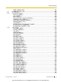
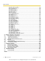
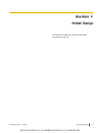


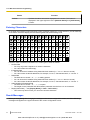
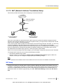

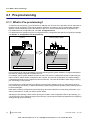

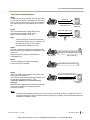
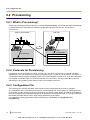
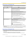


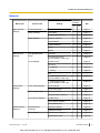
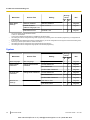
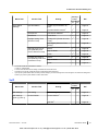
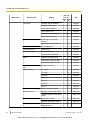
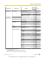
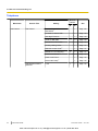
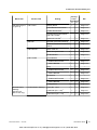

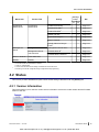

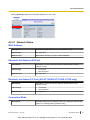

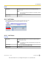
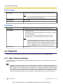
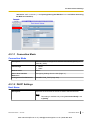

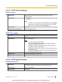


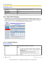
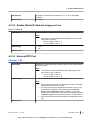
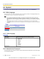

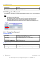

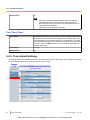
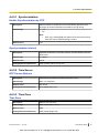
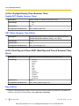


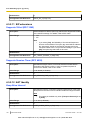

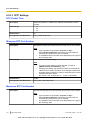

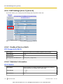


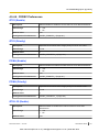


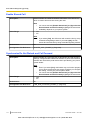

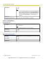
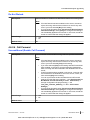


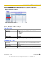
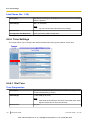
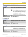
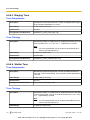

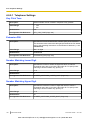
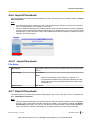
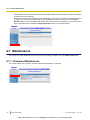
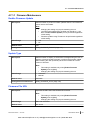
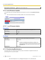
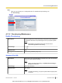
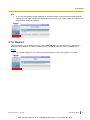


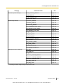
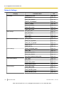

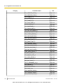


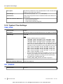


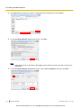
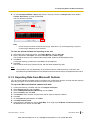

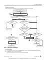

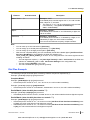


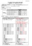


![NS1000 Catalogue 2013 FR v3[1]](http://vs1.manualzilla.com/store/data/006521490_1-da08ed1ed8b3aae265abc6960ec54c95-150x150.png)