1
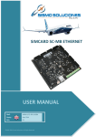
SIMCARD SC-MB ETHERNET
USER MANUAL
Ref:
MAN-US-E-RR-10-007
Date:
October 2010
Ed.:
04
©2005-2013 Sismo Soluciones. All Right Reserved
Flight Simulators
www.sismo-soluciones.com
INDEX
1
Introduction ............................................................................................................................................... 4
1.1
Purpose ............................................................................................................................................. 4
2
Overview .................................................................................................................................................... 4
3
Basic Instructions ....................................................................................................................................... 5
3.1
3.1.1
Supported Components ............................................................................................................... 6
3.1.2
Inputs Map.................................................................................................................................... 7
3.1.3
Outputs Map................................................................................................................................. 9
3.1.4
Displays .......................................................................................................................................10
3.2
SimCard 64 Digital Inputs Daughter Board (SC-64DI-DB) ...............................................................13
3.2.1
Supported Components .............................................................................................................13
3.2.2
Inputs Map..................................................................................................................................14
3.3
SimCard 64 Digital Outputs Daughter Board (SC-64DO-DB) ...........................................................16
3.3.1
Supported Components .............................................................................................................16
3.3.2
Outputs Map...............................................................................................................................17
3.4
3.4.1
3.5
SimCard 14 Servos Daughter Board (SC-14SERV-DB) .....................................................................18
Supported Components .............................................................................................................18
SimCard 32 Displays Daughter Board (SC-32DISP-DB)....................................................................19
3.5.1
Supported Components .............................................................................................................19
3.5.2
Outputs Map...............................................................................................................................19
3.6
3.6.1
3.7
4
SimCard Mother Board (SC-MB) ....................................................................................................... 6
SimCard 11 Analog Input Daughter Board (SC-11AI-DB) ................................................................21
Supported Components .............................................................................................................21
Fast Interface and Interconnection Card (GIC V3.5) .......................................................................21
Installation and Configuration .................................................................................................................22
4.1
Previous requirements....................................................................................................................22
4.2
Hardware Configuration of the Board ............................................................................................22
4.2.1
4.3
Configuration Page and IP Address of the SC-MB Ethernet .......................................................24
Example of Connection Scheme Type .............................................................................................33
5
Hardware Test .........................................................................................................................................34
6
Flight Simulator Use.................................................................................................................................37
7
Others Applications .................................................................................................................................38
04
USER MANUAL
SIMCARD SC-MB ETHERNET
User Manual - SimCard SC-MB Ethernet - Ed4.docx
MAN-US-E-RR-10-007
2
Flight Simulators
www.sismo-soluciones.com
8
FAQs .........................................................................................................................................................39
04
USER MANUAL
SIMCARD SC-MB ETHERNET
User Manual - SimCard SC-MB Ethernet - Ed4.docx
MAN-US-E-RR-10-007
3
Flight Simulators
www.sismo-soluciones.com
1
1.1
INTRODUCTION
PURPOSE
The intention of this document is to describe a global overview of the new SimCard SC-MB Mother Board
Ethernet.
2
OVERVIEW
Welcome to one of the boards of the Simcards
family named SC-MB, specially designed for the
control and management of inputs and outputs of
equipments and modules of simulators made or not
by Sismo, as well as also of any other equipment or
system that it needs of its service.
This new generation of electronic board has
supposed a new challenge for Sismo Soluciones
reaching in this aspect, equivalent levels of
technology, functionality and benefits as those of
the current professional industry.
The main characteristic of the board is so striking as
that its connection is made by means of an Ethernet
bus which is a standard of networks of computers of
local area. In this way, it will be possible to do direct
connection to the equipment or computer of control
as with a bus USB 2.0 but with the advantage of that
the communications and transfer of data will be
much more effective and rapid. These properties are
important for systems of real time as the simulators.
The Ethernet bus awards the possibility of allowing to centralize the wires of a network or to be able to
extend it connecting the board through Switch or Hub devices. According to this, it also is possible to
control the board to long distance through Internet to do checkups of the hardware, etc. as well as
connection through WIFI Wireless by means of a computer connected to the local network in which the
board is connected, that means a real revolution for the flight simulators.
Other one of the new characteristics and not less important is that this board works as “mother card”,
being only necessary a SimCard SC-MB Ethernet to manage and control everything, but logically with a limit
of inputs and outputs.
04
USER MANUAL
SIMCARD SC-MB ETHERNET
User Manual - SimCard SC-MB Ethernet - Ed4.docx
MAN-US-E-RR-10-007
4
Flight Simulators
www.sismo-soluciones.com
This is not a limitation problem, quite the opposite, because the board also has enabled connectors for the
connection of expanding or “daughters boards” according to the needs of a major number of inputs,
outputs, etc. It can be connected so many Daughters Boards like is needed. The type of connection is by
means of a simple flat cable which will join in a direct manner the Mother board with all the Daughter
Boards respectively. These connectors are a standard of connection and therefore they are also compatible
with other boards or components.
We name family of Simcards SC-MB boards to the group formed by the Mother Board and each of the types
of the Daughters Boards which can be connected.
Its control can be made by means of programming in SC Pascal language, which specifically has been
developed by Sismo Soluciones and which can be downloaded for free. Nevertheless they are prepared to
accede by any other type of language with a previous programming configuration of the board.
For those users who do not have many computing knowledge, but have the illusion to build a flight
simulator, in Sismo web and different forums, they will find examples of how programming easily the board
as well as scripts for diverse simulators.
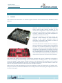
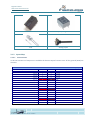
3
BASIC INSTRUCTIONS
In the following picture appears the whole range of boards developed by Sismo Soluciones:
ID
Function
SC-MB
SimCard Mother Board
SC-64DI-DB
SimCard 64 Digital Inputs Daugther Board
SC-64DO-DB
SimCard 64 Digital Outputs Daugther Board
SC-14SERV-DB
SimCard 14 Servos Daugther Board
SC-32DISP-DB
SimCard 32 Displays Daugther Board
SC-11AI-DB
SimCard 11 Analog Inputs Daugther Board
04
USER MANUAL
SIMCARD SC-MB ETHERNET
User Manual - SimCard SC-MB Ethernet - Ed4.docx
MAN-US-E-RR-10-007
5
Flight Simulators
www.sismo-soluciones.com
3.1
SIMCARD MOTHER BOARD (SC-MB)
The Mother Board is connected to the network by means
of an Ethernet port and can expand its functionalities by
means of Daughter Boards. The board has connection for
5V DC.
The inputs / outputs that it has, are the following:
64 Digital Inputs. IDC40.
64 Digital TTL Outputs. IDC40.
32 Displays of 7 segments common cathode. IDC40.
5 Analog Inputs.
3.1.1 Supported Components
The components that can be connected to this board are all kinds of switches, push-buttons, rotarys,
encoder, leds, displays, reles, etc. The most habitual components are:
Rotary Encoders
Switch Buttons
Push Bottons
Rotary Switch
04
USER MANUAL
SIMCARD SC-MB ETHERNET
User Manual - SimCard SC-MB Ethernet - Ed4.docx
MAN-US-E-RR-10-007
6
Flight Simulators
www.sismo-soluciones.com
Reles
Displays 7 Segments
Leds
Analog Inputs
3.1.2 Inputs Map
3.1.2.1
DI1 Connector
In this IDC connector of 40 pines are available the discreet inputs from 01 to 32. All the grounds (GND) are
common.
DI1 CONNECTOR – IDC40
Digital Inputs
Input Number
04
PIN
PIN
Input 01
1
2
Input 02
Input Number
Input 03
3
4
Input 04
Input 05
5
6
Input 06
Input 07
7
8
Input 08
VCC +5V
9
10
GND
Input 09
11
12
Input 10
Input 11
13
14
Input 12
Input 13
15
16
Input 14
Input 15
17
18
Input 16
VCC +5V
19
20
GND
Input 17
21
22
Input 18
Input 19
23
24
Input 20
Input 21
25
26
Input 22
Input 23
27
28
Input 24
VCC +5V
29
30
GND
Input 25
31
32
Input 26
Input 27
33
34
Input 28
USER MANUAL
SIMCARD SC-MB ETHERNET
User Manual - SimCard SC-MB Ethernet - Ed4.docx
MAN-US-E-RR-10-007
7
Flight Simulators
www.sismo-soluciones.com
3.1.2.2
Input 29
35
36
Input 30
Input 31
37
38
Input 32
VCC +5V
39
40
GND
DI2 Connector
In this IDC connector of 40 pines are available the discreet inputs from 33 to 64. All the grounds (GND) are
common.
DI2 CONNECTOR– IDC40
Digital Inputs
Input Number
04
PIN
PIN
Input Number
Input 33
1
2
Input 34
Input 35
3
4
Input 36
Input 37
5
6
Input 38
Input 39
7
8
Input 40
VCC +5V
9
10
GND
Input 41
11
12
Input 42
Input 43
13
14
Input 44
Input 45
15
16
Input 46
Input 47
17
18
Input 48
VCC +5V
19
20
GND
Input 49
21
22
Input 50
Input 51
23
24
Input 52
Input 53
25
26
Input 54
Input 55
27
28
Input 56
VCC +5V
29
30
GND
Input 57
31
32
Input 58
Input 59
33
34
Input 60
Input 61
35
36
Input 62
Input 63
37
38
Input 64
VCC +5V
39
40
GND
USER MANUAL
SIMCARD SC-MB ETHERNET
User Manual - SimCard SC-MB Ethernet - Ed4.docx
MAN-US-E-RR-10-007
8
Flight Simulators
www.sismo-soluciones.com
3.1.3 Outputs Map
The Mother Board has a total of 64 outputs in common cathode configuration which are distributed in two
connectors of 40 pines each one, this means that the common part of all the outputs is the negative
(cathode).
The scheme of connection in common cathode format for the
connection of leds is shown in this image.
3.1.3.1
DO1 Connector
In this IDC connector of 40 pines are available the discreet outputs from 01 to 32. All the grounds (GND) are
common.
DO1 CONNECTOR– IDC40
Digital Outputs
Output Number
04
PIN
PIN
Output Number
Output 01
1
2
Output 02
Output 03
3
4
Output 04
Output 05
5
6
Output 06
Output 07
7
8
Output 08
VCC +5V
9
10
GND
Output 09
11
12
Output 10
Output 11
13
14
Output 12
Output 13
15
16
Output 14
Output 15
17
18
Output 16
VCC +5V
19
20
GND
Output 17
21
22
Output 18
Output 19
23
24
Output 20
Output 21
25
26
Output 22
Output 23
27
28
Output 24
VCC +5V
29
30
GND
Output 25
31
32
Output 26
Output 27
33
34
Output 28
Output 29
35
36
Output 30
Output 31
37
38
Output 32
VCC +5V
39
40
GND
USER MANUAL
SIMCARD SC-MB ETHERNET
User Manual - SimCard SC-MB Ethernet - Ed4.docx
MAN-US-E-RR-10-007
9
Flight Simulators
www.sismo-soluciones.com
3.1.3.2
DO2 Connector
In this IDC connector of 40 pines are available the discreet outputs from 33 to 64. All the grounds (GND) are
common.
DO2 CONNECTOR– IDC40
Digital Outputs
Output Number
PIN
PIN
Output Number
Output 33
1
2
Output 34
Output 35
3
4
Output 36
Output 37
5
6
Output 38
Output 39
7
8
Output 40
VCC +5V
9
10
GND
Output 41
11
12
Output 42
Output 43
13
14
Output 44
Output 45
15
16
Output 46
Output 47
17
18
Output 48
VCC +5V
19
20
GND
Output 49
21
22
Output 50
Output 51
23
24
Output 52
Output 53
25
26
Output 54
Output 55
27
28
Output 56
VCC +5V
29
30
GND
Output 57
31
32
Output 58
Output 59
33
34
Output 60
Output 61
35
36
Output 62
Output 63
37
38
Output 64
VCC +5V
39
40
GND
3.1.4 Displays
The Mother Board has a total of 32 displays of 7 segments of common cathode
which are distributed in two connectors IDC of 40 pines each one.
04
USER MANUAL
SIMCARD SC-MB ETHERNET
User Manual - SimCard SC-MB Ethernet - Ed4.docx
MAN-US-E-RR-10-007
10
Flight Simulators
www.sismo-soluciones.com
3.1.4.1
DY1 Connector
In this IDC connector of 40 pines are available 16 displays of 7 segments, from Display 00 to Display 15. All
the grounds (GND) are common.
DY1 CONNECTOR– IDC40
Displays
PIN
PIN
Seg_A 1
1
2
Seg_B 1
Seg_C 1
3
4
Seg_D 1
Seg_E 1
5
6
Seg_F 1
Seg_G 1
7
8
Seg_DP 1
GND
9
10
GND
Display 00
Dig_0 1
11
12
Dig_1 1
Display 01
Display 02
Dig_2 1
13
14
Dig_3 1
Display 03
Display 04
Dig_4 1
15
16
Dig_5 1
Display 05
Display 06
Dig_6 1
17
18
Dig_7 1
Display 07
GND
19
20
GND
Seg_A 2
21
22
Seg_B 2
Seg_C 2
23
24
Seg_D 2
Seg_E 2
25
26
Seg_F 2
Seg_G 2
27
28
Seg_DP 2
GND
29
30
GND
Display 08
Dig_0 2
31
32
Dig_1 2
Display 09
Display 10
Dig_2 2
33
34
Dig_3 2
Display 11
Display 12
Dig_4 2
35
36
Dig_5 2
Display 13
Display 14
Dig_6 2
37
38
Dig_7 2
Display 15
GND
39
40
GND
04
USER MANUAL
SIMCARD SC-MB ETHERNET
User Manual - SimCard SC-MB Ethernet - Ed4.docx
MAN-US-E-RR-10-007
11
Flight Simulators
www.sismo-soluciones.com
3.1.4.2
DY2 Connector
In this IDC connector of 40 pines are available 16 displays of 7 segments, from Display 16 to Display 31. All
the grounds (GND) are common.
DY2 CONNECTOR– IDC40
Displays
PIN
PIN
Seg_A 3
1
2
Seg_B 3
Seg_C 3
3
4
Seg_D 3
Seg_E 3
5
6
Seg_F 3
Seg_G 3
7
8
Seg_DP 3
GND
9
10
GND
Display 16
Dig_0 3
11
12
Dig_1 3
Display 17
Display 18
Dig_2 3
13
14
Dig_3 3
Display 19
Display 20
Dig_4 3
15
16
Dig_5 3
Display 21
Display 22
Dig_6 3
17
18
Dig_7 3
Display 23
GND
19
20
GND
Seg_A 4
21
22
Seg_B 4
Seg_C 4
23
24
Seg_D 4
Seg_E 4
25
26
Seg_F 4
Seg_G 4
27
28
Seg_DP 4
GND
29
30
GND
Display 24
Dig_0 4
11
12
Dig_1 4
Display 25
Display 26
Dig_2 4
13
14
Dig_3 4
Display 27
Display 28
Dig_4 4
15
16
Dig_5 4
Display 29
Display 30
Dig_6 4
17
18
Dig_7 4
Display 31
GND
39
40
GND
04
USER MANUAL
SIMCARD SC-MB ETHERNET
User Manual - SimCard SC-MB Ethernet - Ed4.docx
MAN-US-E-RR-10-007
12
Flight Simulators
www.sismo-soluciones.com
3.2
SIMCARD 64 DIGITAL INPUTS DAUGHTER BOARD (SC-64DI-DB)
This board is connected by means of a flat cable of 10
wires to the Mother Board.
Each board has 64 digital inputs and 2 boards of this
type can be connected up to the Mother Board.
The Mother Board can manage 192 digital inputs with
two connected boards.
3.2.1 Supported Components
The components that can be connected up to this board are all kinds of switches, push-buttons, rotarys,
encoder, etc. The most habitual components are:
Rotary Encoders
Switch Buttons
Push Bottons
Rotary Switch
04
USER MANUAL
SIMCARD SC-MB ETHERNET
User Manual - SimCard SC-MB Ethernet - Ed4.docx
MAN-US-E-RR-10-007
13
Flight Simulators
www.sismo-soluciones.com
3.2.2 Inputs Map
The map of connections of this board is distributed in 2 available connectors as is described next:
3.2.2.1
Inputs - DI1 Connector
In this IDC connector of 40 pines are available the discreet inputs from 01 to 32. All the grounds (GND) are
common.
DI1 CONNECTOR – IDC40
Digital Inputs
Input Number
04
PIN
PIN
Input 01
1
2
Input 02
Input Number
Input 03
3
4
Input 04
Input 05
5
6
Input 06
Input 07
7
8
Input 08
VCC +5V
9
10
GND
Input 09
11
12
Input 10
Input 11
13
14
Input 12
Input 13
15
16
Input 14
Input 15
17
18
Input 16
VCC +5V
19
20
GND
Input 17
21
22
Input 18
Input 19
23
24
Input 20
Input 21
25
26
Input 22
Input 23
27
28
Input 24
VCC +5V
29
30
GND
Input 25
31
32
Input 26
Input 27
33
34
Input 28
Input 29
35
36
Input 30
Input 31
37
38
Input 32
VCC +5V
39
40
GND
USER MANUAL
SIMCARD SC-MB ETHERNET
User Manual - SimCard SC-MB Ethernet - Ed4.docx
MAN-US-E-RR-10-007
14
Flight Simulators
www.sismo-soluciones.com
3.2.2.2
Inputs - DI2 Connector
In this IDC connector of 40 pines are available the discreet inputs from 33 to 64. All the grounds (GND) are
common.
DI2 CONNECTOR – IDC40
Digital Inputs
Input Number
04
PIN
PIN
Input Number
Input 33
1
2
Input 34
Input 35
3
4
Input 36
Input 37
5
6
Input 38
Input 39
7
8
Input 40
VCC +5V
9
10
GND
Input 41
11
12
Input 42
Input 43
13
14
Input 44
Input 45
15
16
Input 46
Input 47
17
18
Input 48
VCC +5V
19
20
GND
Input 49
21
22
Input 50
Input 51
23
24
Input 52
Input 53
25
26
Input 54
Input 55
27
28
Input 56
VCC +5V
29
30
GND
Input 57
31
32
Input 58
Input 59
33
34
Input 60
Input 61
35
36
Input 62
Input 63
37
38
Input 64
VCC +5V
39
40
GND
USER MANUAL
SIMCARD SC-MB ETHERNET
User Manual - SimCard SC-MB Ethernet - Ed4.docx
MAN-US-E-RR-10-007
15
Flight Simulators
www.sismo-soluciones.com
3.3
SIMCARD 64 DIGITAL OUTPUTS DAUGHTER BOARD (SC-64DO-DB)
This board is connected by means of a flat cable of 10
wires to the Mother Board.
Each board has 64 digital outputs and 2 boards of this
type can be connected up to the Mother Board.
The Mother Board can manage 192 digital outputs with
two connected boards.
3.3.1 Supported Components
The components that can be connected up to this board are all leds, reles, etc. The most habitual
components are:
Reles
04
Leds
USER MANUAL
SIMCARD SC-MB ETHERNET
User Manual - SimCard SC-MB Ethernet - Ed4.docx
MAN-US-E-RR-10-007
16
Flight Simulators
www.sismo-soluciones.com
3.3.2 Outputs Map
3.3.2.1
Outputs - DO1 Connector
In this IDC connector of 40 pines are available the discreet outputs from 01 to 32. All the grounds (GND) are
common.
DO1 CONNECTOR – IDC40
Digital Outputs
Output Number
3.3.2.2
PIN
PIN
Output 01
1
2
Output 02
Output Number
Output 03
3
4
Output 04
Output 05
5
6
Output 06
Output 07
7
8
Output 08
VCC +5V
9
10
GND
Output 09
11
12
Output 10
Output 11
13
14
Output 12
Output 13
15
16
Output 14
Output 15
17
18
Output 16
VCC +5V
19
20
GND
Output 17
21
22
Output 18
Output 19
23
24
Output 20
Output 21
25
26
Output 22
Output 23
27
28
Output 24
VCC +5V
29
30
GND
Output 25
31
32
Output 26
Output 27
33
34
Output 28
Output 29
35
36
Output 30
Output 31
37
38
Output 32
VCC +5V
39
40
GND
Outputs – DO2 Connector
In this IDC connector of 40 pines are available the discreet outputs from 33 to 64. All the grounds (GND) are
common.
DO2 CONNECTOR – IDC40
Digital Outputs
Output Number
04
PIN
PIN
Output Number
Output 33
1
2
Output 34
Output 35
3
4
Output 36
Output 37
5
6
Output 38
Output 39
7
8
Output 40
VCC +5V
9
10
GND
Output 41
11
12
Output 42
Output 43
13
14
Output 44
USER MANUAL
SIMCARD SC-MB ETHERNET
User Manual - SimCard SC-MB Ethernet - Ed4.docx
MAN-US-E-RR-10-007
17
Flight Simulators
www.sismo-soluciones.com
3.4
Output 45
15
16
Output 46
Output 47
17
18
Output 48
VCC +5V
19
20
GND
Output 49
21
22
Output 50
Output 51
23
24
Output 52
Output 53
25
26
Output 54
Output 55
27
28
Output 56
VCC +5V
29
30
GND
Output 57
31
32
Output 58
Output 59
33
34
Output 60
Output 61
35
36
Output 62
Output 63
37
38
Output 64
VCC +5V
39
40
GND
SIMCARD 14 SERVOS DAUGHTER BOARD (SC-14SERV-DB)
This board is connected by means of a flat cable of 10
wires to the Mother Board.
Each board can control 14 servos and a board of this
type can be connected up to the Mother Board.
The Mother Board can manage 14 servos with a
connected board.
3.4.1 Supported Components
This board supports any type of servo in their different formats:
Servos
04
USER MANUAL
SIMCARD SC-MB ETHERNET
User Manual - SimCard SC-MB Ethernet - Ed4.docx
MAN-US-E-RR-10-007
18
Flight Simulators
www.sismo-soluciones.com
3.5
SIMCARD 32 DISPLAYS DAUGHTER BOARD (SC-32DISP-DB)
This board is connected by means of a flat cable of
10 wires to the Mother Board.
Each board can control 32 displays of 7 segments in
common cathodes and a board of this type can be
connected up to the Mother Board.
The Mother Board can manage 64 displays with a
connected board.
3.5.1 Supported Components
This board supports any type of display of 7 segments in common cathode:
Displays 7 Segments
3.5.2 Outputs Map
3.5.2.1
Displays - DY1 Connector
In this IDC connector of 40 pines are available 16 displays of 7 segments, from Display 00 to Display 15. All
the grounds (GND) are common.
DY1 CONNECTOR – IDC40
Displays
PIN
PIN
Seg_A 1
1
2
Seg_B 1
Seg_C 1
3
4
Seg_D 1
Seg_E 1
5
6
Seg_F 1
Seg_G 1
7
8
Seg_DP 1
GND
9
10
GND
Display 00
Dig_0 1
11
12
Dig_1 1
Display 01
Display 02
Dig_2 1
13
14
Dig_3 1
Display 03
Display 04
Dig_4 1
15
16
Dig_5 1
Display 05
Display 06
Dig_6 1
17
18
Dig_7 1
Display 07
04
GND
19
20
GND
Seg_A 2
21
22
Seg_B 2
Seg_C 2
23
24
Seg_D 2
Seg_E 2
25
26
Seg_F 2
USER MANUAL
SIMCARD SC-MB ETHERNET
User Manual - SimCard SC-MB Ethernet - Ed4.docx
MAN-US-E-RR-10-007
19
Flight Simulators
www.sismo-soluciones.com
3.5.2.2
Seg_G 2
27
28
Seg_DP 2
GND
29
30
GND
Display 08
Dig_0 2
31
32
Dig_1 2
Display 09
Display 10
Dig_2 2
33
34
Dig_3 2
Display 11
Display 12
Dig_4 2
35
36
Dig_5 2
Display 13
Display 14
Dig_6 2
37
38
Dig_7 2
Display 15
GND
39
40
GND
Displays - DY2 Connector
In this IDC connector of 40 pines are available 16 displays of 7 segments, from Display 16 to Display 31. All
the grounds (GND) are common.
DY2 CONNECTOR – IDC40
Displays
PIN
PIN
Seg_A 3
1
2
Seg_B 3
Seg_C 3
3
4
Seg_D 3
Seg_E 3
5
6
Seg_F 3
Seg_G 3
7
8
Seg_DP 3
GND
9
10
GND
Display 16
Dig_0 3
11
12
Dig_1 3
Display 17
Display 18
Dig_2 3
13
14
Dig_3 3
Display 19
Display 20
Dig_4 3
15
16
Dig_5 3
Display 21
Display 22
Dig_6 3
17
18
Dig_7 3
Display 23
GND
19
20
GND
Seg_A 4
21
22
Seg_B 4
Seg_C 4
23
24
Seg_D 4
Seg_E 4
25
26
Seg_F 4
Seg_G 4
27
28
Seg_DP 4
GND
29
30
GND
Display 24
Dig_0 4
11
12
Dig_1 4
Display 25
Display 26
Dig_2 4
13
14
Dig_3 4
Display 27
Display 28
Dig_4 4
15
16
Dig_5 4
Display 29
Display 30
Dig_6 4
17
18
Dig_7 4
Display 31
GND
39
40
GND
04
USER MANUAL
SIMCARD SC-MB ETHERNET
User Manual - SimCard SC-MB Ethernet - Ed4.docx
MAN-US-E-RR-10-007
20
Flight Simulators
www.sismo-soluciones.com
3.6
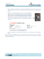
SIMCARD 11 ANALOG INPUT DAUGHTER BOARD (SC-11AI-DB)
This board is connected by means of a flat cable of 10
wires to the Mother Board.
Each board can control 11 Analog Inputs (pots) and a
board of this type can be connected up to the Mother
Board.
The Mother Board can manage 16 Analog Inputs (pots)
with a connected board.
<FOTO>
3.6.1 Supported Components
This board supports any type of pots:
Pots
3.7
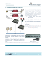
FAST INTERFACE AND INTERCONNECTION CARD (GIC V3.5)
The GIC V3.5 Boards (General Interface Card) facilitate
the connections with the different components, because
they allow to connect backpanels with IDC connectors of
less than 40 pins or allow to connect components by
means of free wiring to threaded terminals, so it will not
be necessary welds. Of this form, the connections are
easy to make, are clean and allow a better maintenance,
beside giving a bigger reliability to any solution.
For it, a GIC V3.5 can be connected to the IDC connectors of 40 pins of any of the SimCards and in this way
already it is possible to access to the different pins both by flat cables and by free wiring.
04
USER MANUAL
SIMCARD SC-MB ETHERNET
User Manual - SimCard SC-MB Ethernet - Ed4.docx
MAN-US-E-RR-10-007
21
Flight Simulators
www.sismo-soluciones.com
4
4.1
INSTALLATION AND CONFIGURATION
PREVIOUS REQUIREMENTS
They are compatible with any operating system; it only is necessary to have a computer with an ETHERNET
free port. It is also possible to use a HUB or SWITCH that allows to centralize the wired up of a network and
to be able to extend it.
There are two ways of connecting the Mother Board to the control computer:
1. By direct way with only a cable: it is necessary a crossed cable type
that connects the Mother Board with the computer.
2. By means of a Switch or Hub: it can be used indistinctly a crossed
cable or a normal cable.
The normal situation is that the Board is connected to the computer where Microsoft Flight Simulator is
installed, because it must accede to its functions through the IOCP or of FSUIPC communication protocol
which is going to be used. Nevertheless, in network configuration, the Board can be connected to other
computers, but for that purpose the network must be configured adequately, and this is not inside the area
of this manual. Anyway, this manual will be useful for orientating to the user how he must do it.
4.2
HARDWARE CONFIGURATION OF THE BOARD
To configure the Board, and once the connection to
the control computer is made, directly or by means
of a Switch or Hub, proceed to supply externally the
Ethernet SC-MMB Mother Board.
Optional Note: It is recommended to have the rest
of hardware and computers disconnected from the
network for configuring the Board.
It is indispensable that the voltage of supply that is
received in the terminals of the Board is 5V DC.
A lower voltage is not enough for a well-functioning of the Board and a higher voltage can damage the
connected servos.
The scheme on the right shows the correct manner to supply the Board.
04
USER MANUAL
SIMCARD SC-MB ETHERNET
User Manual - SimCard SC-MB Ethernet - Ed4.docx
MAN-US-E-RR-10-007
22
Flight Simulators
www.sismo-soluciones.com
IMPORTANT: the Board might be
affected if the positive and negative
terminals are not the shown ones in the
scheme.
- +
For those users who do not want to use
the green threaded terminals, it is
possible to supply the Board through a
connector qualified to do it (DC_CON).
5.0
For safety, also check with a multimeter
that the voltaje in the terminals of the
scheme is 5V DC.
220 Vca
{
From this moment the Board must be
perfectly connected through Ethernet
bus to the control computer or the
network.
+V
ADJ
+V
+V
COM COM
(AC)
N
L
F.A. 5 Vcc
In the SC-MB SimCards family are 4 types of JUMPERS. Each one has a specific function.
When purchasing the Board, the user will find the jumpers properly located in their places by default. The
advice is not to change the place of the jumpers and do not remove it unless the user has a particular
interest to.
For those ones who are interested, the table below shows the function of the each jumper.
The jumpers JP_PGC and JP_PGD must be always
placed, because they are the managers of the
programming of the chip of the Mother Board
and in case to be removed, the Board will stop
working.
04
USER MANUAL
SIMCARD SC-MB ETHERNET
User Manual - SimCard SC-MB Ethernet - Ed4.docx
MAN-US-E-RR-10-007
23
Flight Simulators
www.sismo-soluciones.com
In the same way, if the JP1 jumper is removed,
the inputs of the Board will be disabled. The JP1
jumper provides the possibility of selecting the
wished logic for the Inputs, that is to say, if we
change the cover of the jumper from the 1-2 pins
to the 2-3 pins, the logic will be reversed in a
sense or other one as is convenient for the user.
This type of jumpers can be located in the
Mother Board and in the Inputs Daughter Board.
The JP2 jumper, which only is localizable in the
Mother Board. It will always have to be placed
between the central pin and +5V.
The advice now is to check visually that the jumpers are located in their correct place to ensure the
optimum performance of the Board.
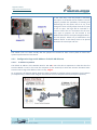
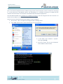
4.2.1 Configuration Page and IP Address of the SC-MB Ethernet
4.2.1.1
IP Address by Default
The default IP address of the Mother Board is 192.168.1.150. This data is important in order that the first
time the Board is read. In this case the computer (or the network) in which we connect the Board must
have the same range of IP address, that is to say, range 1.
As an example, the diagram below shows the items required to configure a basic network or local network
(1 computer only). Later another diagram will illustrate a more complex network (multiple computers).
04
USER MANUAL
SIMCARD SC-MB ETHERNET
User Manual - SimCard SC-MB Ethernet - Ed4.docx
MAN-US-E-RR-10-007
24
Flight Simulators
www.sismo-soluciones.com
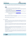
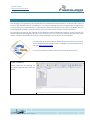
See in the above example that the IP address range of the control computer, which is marked in red (range
1), is the same that in the Mother Board. This specification is a condition necessary to enable that the
network communication occurs between the Mother Board and other equipments.
Like the Mother Board has by default an IP address of range 1, the first thing that the user must do is to
check if the IP address of the control computer has also range 1.
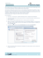
Here's one way to know the personal IP address of your computer:
1. Go to: Start -> Run. An input box will appear with a flashing cursor.
2. Type: cmd. Click on OK or press the Enter key on your keyboard.
3. A new black color window is opened.
Here type: ipconfig
4. Press the “Enter” key on your keyboard
and IP Address will be shown.
04
USER MANUAL
SIMCARD SC-MB ETHERNET
User Manual - SimCard SC-MB Ethernet - Ed4.docx
MAN-US-E-RR-10-007
25
Flight Simulators
www.sismo-soluciones.com
The user does not have to change the IP address of the control computer if it turns out to be range 1. That
is to say, that the equipment is already configured with a right IP address.
If the control computer does not have range 1 as in the previous example which the IP address is range 2
(see green box and inside yellow box), the user must temporarily change the IP address of his control
computer to range 1 in order that the card can be read by the computer the first time, because as it was
noted above, the Mother Board comes with a default IP address of range 1.
Follow the next steps to change the IP address of the control computer:
E.g. for Windows 7:
1. Go to: Start -> Control panel -> Network and Sharing Center-> Configuración del adaptador.
2. Press with the right button of the mouse on the icon of "Local Area Connection" and later press on
General Properties.
3. After a window is opened. Make double click on "Internet protocol v4 (TCP/IPv4)".
4. Again a new window is opened. Mark the option "Use the following IP Address" in order that the
zone where it will be possible to write the new IP address of the control computer is enabled (Ej: IP
address 192.168.1.101).
5. As “subnet mask” to write for example 255.255.255.0 and in the third field 192.168.1.1
6. Finally, the windows will be closed when "Ok (Aceptar)" has been pressed. From this moment the
change has been saved.
04
USER MANUAL
SIMCARD SC-MB ETHERNET
User Manual - SimCard SC-MB Ethernet - Ed4.docx
MAN-US-E-RR-10-007
26
Flight Simulators
www.sismo-soluciones.com
7. Once the process has finished, both the IP address of the Board and the IP of the control computer
will have the same range, in this case range 1. Now to accede to the configuration page of the
Board will be possible.
Note-1: This is only an example for Windows 7 in an orientated way. The way of changing the IP for other
operating systems can be found into multiple tutorials or Internet.
Nota-2: Find also video tutorials at the section of “Technical
Videos” in the main SISMO SOLUCIONES web page, and learn
better how to configure the Mother Board, change the IP
Address, etc.
As we will see along the manual, this provisional change in the IP address does not suppose a problem for
the configuration of the rest of equipments that the user had previously, because once we accede to the
configuration page of the SC-MB Boards, it will be possible to restore the previous IP addresses as well as
give a new IP address to the Mother Board with the IP range that the user wants to use in the set of his
equipments.
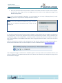
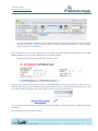
Now, for being able to accede to the configuration of the Board is necessary to open Internet Explorer.
Write inside of the address bar in Internet Explorer the IP of the Mother Board: http://192.168.1.150/
The configuration page is loaded and as headline appears the serial number of the Mother Board in red
colour in addiction of the CONFIG PAGE words which indicate that effectively the configuration page of the
Board has been charged.
04
USER MANUAL
SIMCARD SC-MB ETHERNET
User Manual - SimCard SC-MB Ethernet - Ed4.docx
MAN-US-E-RR-10-007
27
Flight Simulators
www.sismo-soluciones.com
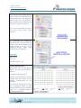
Three configuration fields appear: NETWORK CONFIG, UDP CONFIG and DAUGHTER BOARDS CONFIG. All
these fields have the values by default. For its correct configuration, there is detailed the meaning, content
and way to proceed in each item:
4.2.1.2
-
Network Config
MAC ADDRESS: it is the hardware address of the Mother Board and therefore, it is unique and
cannot be modified.
The last four digits are in hexadecimal and give name to the variable part of the serial number of
the Board. The invariable part is fixed as SC-MB:
SC-MMBnnnn
Please don’t forget this number. Probably you will need in several applications. The serial number
of the Board will be also used to accede to its functionalities when someone is going to program in
SC-Pascal.
-
IP ADDRESS: this section is used to modify the IP address of the Mother Board which has by default
198.168.1.150.
In case of being modified, do not forget that it must have the same IP range that the IP address of
the control computer. It is the moment to proceed to restore the IP address which the user had
configured its equipment.
04
USER MANUAL
SIMCARD SC-MB ETHERNET
User Manual - SimCard SC-MB Ethernet - Ed4.docx
MAN-US-E-RR-10-007
28
Flight Simulators
www.sismo-soluciones.com
Note: the new assigned IP address of the Mother Board must not be repeated in any other
hardware or equipment of the network, otherwise it will create conflict and will not load correctly.
Example:
1. Before the control computer had the next IP address: 192.168.2.200.
2. We must remember that for acceding to the configuration page, the IP of the control computer
must have the same range that the Board. Therefore, proceed to change the IP address of the
computer to 192.168.1.200.
3. Go to the configuration page with the direction: http://192.168.1.150/
4. Change the default IP of the Mother Board to 192.168.2.150 bearing in mind that is not
repeated by other one of the equipments that are used in the network.
5. Change again the IP address of the control computer to the same one that the user had before.
6. Go to the configuration page with the direction: http://192.168.2.150/
*Watch video tutorials at the “Technical Videos” section of the main page of SISMO
SOLUCIONES web.
-
MASK: in this section we advise to put the same number of mask that you have in the control
computer of the network. By default it is: 255.255.255.0
-
DEFAULT GATEWAY: it can be used to send information through Internet. If you are not going to
use it, leave the value by default: 192.168.1.1
4.2.1.3
UDP Config
-
HOST IP: it is the IP address of the control computer where the Mother Board will send all the
information. As already it has been mentioned, the IP address of the computer must have the same
range that the IP address of the Mother Board named in the section IP ADDRESS. The value that
appears by default is 192.168.1.19.
-
LOCAL PORT: it is the port where the Mother Board is going to get the information from the control
computer. In case of using SC-Pascal, it is necessary to write in this field the number port; 1024.
This port can be modified for those users who try to make and use their own editors and not SCPascal.
-
HOST PORT: it is the port where the control computer is going to get the information from the
Mother Board. In case of using SC-Pascal, the port used by default is; 1026.
This port must be opened (without to be used for any other program and enabled/opened in order
the data can be received).
If the port 1026 is occupied, it will be necessary to indicate another port which the user must
choose (e.g. 1036).
The SC-Pascal V5 Build 150 editor or Superior allows to the user to change the Host Port in the field
"List UDP Port". In order the Board and SC-Pascal are communicated, the port indicated in the
configuration page in the field HOST PORT and the port where SC-Pascal listens which is indicated in
"List UDP Port ", must be the same.
04
USER MANUAL
SIMCARD SC-MB ETHERNET
User Manual - SimCard SC-MB Ethernet - Ed4.docx
MAN-US-E-RR-10-007
29
Flight Simulators
www.sismo-soluciones.com
The normal situation is that the port is enabled/opened, but it is possible that the control computer
has this port closed. In order to assure it works, it must be enabled (see chapter 8, “FAQ” and know
how to open ports in computers).
Once all the sections are correctly filled out as in this manual has been described, proceed to press on SAVE
BOARD CONFIG to save the new configuration of the Mother Board.
Note: Wait at least 5 seconds while the data are saved.
In order that it makes effect and once saved, it is indispensable to close Internet Explorer and to return to
opening. After that the new IP address of the Mother Board must be indicated on the bar of directions. This
step must be done necessarily due to the exigency of the Internet protocol Explorer.
Once the page has been correctly loaded with the new IP address, the information of configuration will be
visualized.
At this moment you can choose 3 options:
04
USER MANUAL
SIMCARD SC-MB ETHERNET
User Manual - SimCard SC-MB Ethernet - Ed4.docx
MAN-US-E-RR-10-007
30
Flight Simulators
www.sismo-soluciones.com
1. Return to modify again some section in which the configuration has not been the required one by
the user and later to save again the new information pressing with the mouse on SAVE BOARD
CONFIG.
2. Make a reset of the Mother Board. It returns to the configuration by
default. It is made on having pressed with the mouse on RESTORE
DEFAULT VALUES in the configuration page or pressing manually more
than 10 seconds on RESET button placed physically on the Mother
Board Ethernet. To make this step, the Board must be correctly
connected to the power supply. With both methods we make the
erased EEPROM (Electrically Erasable Programmable Read-Only
Memory).
3. Finish the configuration of the Mother Board and begin with the configuration of the Daughters
Boards.
Again, and in order that it makes effect, in any of the options 1 or 2 that we have chosen, do not forget to
close and re-open Internet Explorer indicating on the bar of directions the new IP address of the already
configured Mother Board.
04
USER MANUAL
SIMCARD SC-MB ETHERNET
User Manual - SimCard SC-MB Ethernet - Ed4.docx
MAN-US-E-RR-10-007
31
Flight Simulators
www.sismo-soluciones.com
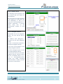
4.2.1.4
Daughter Boards Config
In this field, we must indicate the Daughters Bards which are going to be connected to the Mother Board.
We can mark all those that we wish though they are not connected, but this only will do to slow down the
time of data processing. We advice to mark only the Daughters Boards connected to the Mother Board.
The configuration page allows activating a total of 2
Inputs Daughters Boards, 2 of Outputs, 1 of
Displays, 1 of Servos and 1 ADC (pots). All these are
considered enough to manage any system or
equipment with a great number of inputs/outputs.
Pressing with the mouse on SAVE DAUGHTER is enough for finishing the configuration and activation of the
Daughters Boards. It will be saved automatically, not being this time necessarily to restart Internet Explorer.
Once made and saved the configuration of the Mother Board and the Daughters Boards, you will not have
to return to configure anymore unless the user wants to do a specific change in the configuration of the
Boards.
Note: if in some of the necessary steps to configure the Board appears signs of difficulty of load in the
configuration page, do not worry, it is normal and is due to the Internet Protocol Explorer. For solving this
problem, Internet Explore must be closed and restart it indicating on the bar of directions the IP address of
the Board. If this method does not work, proceed to remove the power supply and restart to connect
everything again.
04
USER MANUAL
SIMCARD SC-MB ETHERNET
User Manual - SimCard SC-MB Ethernet - Ed4.docx
MAN-US-E-RR-10-007
32
Flight Simulators
www.sismo-soluciones.com
4.3
EXAMPLE OF CONNECTION SCHEME TYPE
This is an example of network configuration
composed by 2 computers which control and
manage 2 Mother Boards. At the same time,
components, complete flight simulator
modules (SISMO PRMs), etc. are connected to
the Mother Board. For this specific issue, 2
types of configuration can be done:
a) 1 computer which controls both
Mother Boards
b) Each computer controls only one
Mother Board.
The unique requirement to be networked is
that the 4 elements must have the same IP
range.
For example:
192.168.1.150 (Mother Board 1) 192.168.1.151
(Mother Board 2) 192.168.1.152 (computer 1)
192.168.1.153 (computer 2)
Each computer and each Board must have an Ethernet
port (normally used for connecting to the internet
network).
4 Ethernet cables will plugged each of these 4
equipments to a device SWITCH, HUB or ROUTER (with
Autosense) in order a communication between them
occurs.
SWITCH Autosense
In the same used SWITCH, the Ethernet cable to provide connection for internet can also be plugged.
04
USER MANUAL
SIMCARD SC-MB ETHERNET
User Manual - SimCard SC-MB Ethernet - Ed4.docx
MAN-US-E-RR-10-007
33
Flight Simulators
www.sismo-soluciones.com
5
HARDWARE TEST
The language of programming that specifically has developed Sismo Soluciones is SC-Pascal and in spite of
the fact that the Board can be controlled for any another language previous its appropriate configuration,
in this manual only and exclusively is indicated the necessary requirements to control the Board with the
SC-Pascal editor/compiler, being enough for every user who want to interact with the simulator.
SC-Pascal has a section for the checking of the Hardware, Inputs and Outputs, Displays, Servos and Adc’s for
both the Mother and Daughters Boards. In this way the user can verify the hardware, represent the active
inputs, activate or deactivate the outputs, check the displays and verify the servos and adc's.
For being able to do these checks, download the last version of SC Pascal
V5 for SC-MB Simcards's family which is available in the download zone of
the web www.737ngsim.com.
For more information read the manuals and tutorials of SC Pascal.
Screen 1: SC-Pascal
Launch SC-Pascal V5 pressing on
SC-Pascal Logo and this screen will
appear.
04
USER MANUAL
SIMCARD SC-MB ETHERNET
User Manual - SimCard SC-MB Ethernet - Ed4.docx
MAN-US-E-RR-10-007
34
Flight Simulators
www.sismo-soluciones.com
In the left part can be observed the
serial number of the Mother Board
accompanied of all the Daughters
Boards which are connected in
these moment to the computer and
have been correctly configured.
This is only an example, for that it
will never have these serial
numbers.
For launching the application
"Hardware test", do click with the
mouse on the serial number of the
Mother Board or on any of the
Daughters Boards which were
connected and configured.
Color Code:
ON -> green
OFF -> grey
Last active Input -> red
Screen 2: Mother Board
With double click on the Mother
Board the user will be able to
observe:
The INPUTS state (ON/ OFF).
Activate or to deactivate an output
pressing with the mouse on the
number corresponding to the
OUTPUTS.
Do the test of the displays or check
the 5 analogical inputs or pots
marking before the icon "ACTIVATE
ADCn" (n = analogical input to
activating/ deactivate).
04
USER MANUAL
SIMCARD SC-MB ETHERNET
User Manual - SimCard SC-MB Ethernet - Ed4.docx
MAN-US-E-RR-10-007
35
Flight Simulators
www.sismo-soluciones.com
Screen 3: Mother Board
The following screen appears if the
user presses with the mouse on
TEST DISPLAYS.
We can mark the orange segments
of the displays to verify that they
work adequately as well as to
change the intensity/brightness or
activate/ deactivate a concrete
display doing click on the
corresponding number of each
display.
Screen 4: Daughters Boards
With double click on the Daughters
Boards the user will be able to
observe:
The INPUTS state (ON=green /
OFF=grey) for the Input Daughters
Boards.
Activate or deactivate OUTPUTS in
the Output Daughters Boards.
Do the test of the displays in the
Displays Daughters Boards.
Check the analogical inputs or pots
in the ADC Daughters Boards.
And verify the servos in the Servos
Daughters Boards marking before
the icon "ACTIVATE Servo n" (n =
servo to activating/deactivate).
Another icon called "ACTIVATE
YOUR ALL SERV" is used to activate
the 16 servos of the Board.
04
USER MANUAL
SIMCARD SC-MB ETHERNET
User Manual - SimCard SC-MB Ethernet - Ed4.docx
MAN-US-E-RR-10-007
36
Flight Simulators
www.sismo-soluciones.com
6
FLIGHT SIMULATOR USE
With the new SC-MB SimCards you can control all the elements and components of any flight simulator.
Obviously Sismo uses these Boards for the modules of the TERAS 737NG simulator which develops and
commercializes, in this manner the solution offered by Sismo is very complete because not only the user
can have panels and hardware of great quality (TERAS family), in addition it has the electronics of control
needed and certainly the software to interact with the different simulators of the market.
These Boards can be used not only by the modules of Sismo, much more with any other type of modules or
for those who want to build their own simulators, the Boards are ideal together with the GIC cards, and
with this solution forget to have problems with the connections.
No other card of the market offers so much power and so many benefits, besides all the advantages
described in this manual. Could you imagine having a simulator controlled by wireless? With this
technology already it is possible, now we can forget the problems of the quantity of USB ports, the
distances, etc.
Calculate the cards that you need to equalize to an alone SC-MMB, in some cases it is needed until 5
different cards with an obsolete technology. In this case, the final price of these solutions are practically the
same than the solution with an alone SimCard.
Some examples for modules of a 737NG Simulator:
FWD Overhead
1 SimCard Mother SC-MMB Board
3 SimCards Daughter Boards
Notes:
For facilitating the hook-up of a big and completely
connected module as this case is, GIC V2 cards are
used (blue cards).
If the Overhead takes operative gauges for servos, it
is necessary to add a new Daughter Board.
The Overhead has only an Ethernet port for the
whole set and does not need any type of HUB (as in
case of USB).
It has a power connector of 5V.
If this module had the wireless kit, it only would be
necessary to connect supply.
Complete MIP
1 SimCard Mother SC-MMB Board
MCP and EFIS
1 SimCard Mother SC-MMB Board
04
USER MANUAL
SIMCARD SC-MB ETHERNET
User Manual - SimCard SC-MB Ethernet - Ed4.docx
MAN-US-E-RR-10-007
37
Flight Simulators
www.sismo-soluciones.com
7
OTHERS APPLICATIONS
The cards of the SimCards family named SC-MB are specially designed for the control and management of
inputs and outputs of equipments and modules of simulators made or not by Sismo, as well as any other
equipment or system of real time which need control of elements, being some examples of application:
Flight simulators/cars/trains/ etc.
Systems of centralized control, CTC type
Sending of data by remote
Control of elements
Systems of roads
Etc.
04
USER MANUAL
SIMCARD SC-MB ETHERNET
User Manual - SimCard SC-MB Ethernet - Ed4.docx
MAN-US-E-RR-10-007
38
Flight Simulators
www.sismo-soluciones.com
8
FAQS
# ¿How can the user enable/open any port in the computer?
As example, the necessary steps to open manually ports in Windows XP will be explained. For others
operating systems, it can be done after to look for easily how to do it through any internet browser.
1. Click Start, and then click My Network Places.
2. Under Network Tasks, click View Network Connections. (Or, right-click My Network Places on the
desktop, and then click Properties.)
3. Right-click the connection that you use for the Internet, and then click Properties.
4. Click the Advanced tab, and then click Settings.
Note If the Settings button is unavailable, ICF is not enabled on this connection, and you do not
have to open any ports (because they are all already open).
5. Click Add to open a new port.
6. In the Description box, type a friendly name. For example, type File Sharing: Port 445.
7. In the Name or IP address of the computer hosting this service on your network box, type
127.0.0.1.
Note: You can specify the IP address of an internal computer. But you typically will use 127.0.0.1.
8. In the External port and Internal port boxes, type the port number. Generally, this number is the
same.
9. Click UDP, and then click OK.
10. Repeat steps 1 through 9 for each port that you want to open.
Advice: disable completely the Firewall Windows in case to have more than one equipment connected to
the network and improve the communications.
END OF DOCUMENT
04
USER MANUAL
SIMCARD SC-MB ETHERNET
User Manual - SimCard SC-MB Ethernet - Ed4.docx
MAN-US-E-RR-10-007
39