1
Upgrading the Mark5A to Mark5B
P. de Vicente, R. Bolaño
C. Almendros, J. Fernández, J.A. Abad
Informe Técnico IT-OAN 2007-15
1
Histórico de revisiones
Versión
1.0
1.1
1.2
Fecha
06-04-2007
06-05-2007
19-10-2007
Autor
P. de Vicente
P. de Vicente
P. de Vicente
Cambio
version in spanish. Mark5 I/O board upgrade
version in english. Mark5 I/O board upgrade
Main CPU board upgrade.
ÍNDICE
2
Índice
1. Introduction
3
2. Hardware upgrade
3
3. Upgrade of the motherboard, power supply and RAM memory
7
4. Upgrade of the Mark5 OS and software
12
5. Appendix
15
1
1.
INTRODUCTION
3
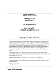
Introduction
We describe the process we followed at the Centro Astronómico de Yebes (CAY) from
the Observatorio Astronómico Nacional (OAN) to upgrade from a Mark5A to a Mark5B. The
Mark5B is a VSI compatible equipment and requires installing a new Mark5 I/O board. We also
describe the upgrade of the motherboard, microprocesor, RAM memories and serial disk so that
the equipment be prepared for e-VLBI.
2.
Hardware upgrade
The following parts were withdrawn from the Mark5A:
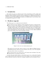
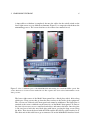
Mark 5A I/O panel. In the Mark5A standard equipments this panel is external and attached to its rear part. If the equipment is to be installed in a rack the extra depth has to be
taken into account to avoid a collision with the rear door of the rack. At the OAN the rack
was 900 cm depth and this was not enough since the Mark5A cables were hitting against
its back door. We moved this panel to the upper cover and made a hole to pass through the
cables. The Mark 5B does not need this board, so the hole was closed with an aluminium
plate at the workshop of the Centro Astronómico de Yebes.
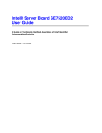
Figura 1: Rear view of the withdrawn Mark5A panel
This panel used several specific cables to connect it to the VLBA and Mark4 formatters.
The Mark5B cannot be connected to these formatters since they are not VSI compatible.
Therefore all these cables were withdrawn.
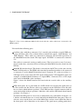
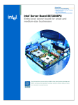
Mark 5A I/O interface board. This board is a PCI board inside the Mark5. The cables
mentioned before were attached to this board.
To remove the panel and the board, we removed the upper cover, cut the plastic ring that
passed along the black handle and hold the board sticked to the rear bus board and unscrewed
the board from the external rear of the box, as happens with PCI boards on standard PC boxes.
2
HARDWARE UPGRADE
4
Figura 2: View of the withdrawn Mark5A I/O board with the cables which were connected to the
Mark5A panel.
We installed the following parts:
Auxiliary plate with three connectors. It is a metalic plate with three coaxial SMB connectors and their cables. Two of them allow to monitor the signals: “DOT Monitor” and
“ROT Monitor”. These cables are connected to connectors J29 and J30 respectively on
the Mark5B I/O interface board. The input signal “ALT1PPS” is connected to connector
J31.
The cables are connected exerting a small pressure. There is no need to screw. It is convenient to make these conections before inserting the Mark5B I/O interface board into the
PCI bus.
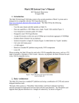
Mark5B I/O interface board. This board is inserted into the PCI bus, in the same slot the
Mark 5A I/O board was. The FPDP cable from the StreamStore board has to be connected
to connector J1 on the Mark5 IO interface board. Connector J27, at the rear of box, is a
VSI input and is used to inject the VSI signal coming from a VSI compatible source (for
example, a modified Mark4 formatter, or a digital BBC). Connector J28 is a VSI output
and is used for Mark5Bs at the correlators.
Figure 3 shows the Mark5 interface I/O board with the coaxial cables to the auxiliary
plate.
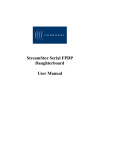
LEDs front panel. It is a panel with one 8 LEDs board and a metal plate with letters on
it. First connect the flat 10 wire cable to its connector on the LED board. The flat cable
has a red wire which indicates position 1. The LED board has a female connector with an
arrow mark which indicates position 1. Both the cable and the LED board should match
position 1. See Figure 4.
To mount the LED panel it is necessary to unmount the two side handles of the box; see
5. Below each handle there are 4 screws that hold the Mark5 black front panel. There are
also two screws on the lower cover of the Mark5 box, and two srews behind the filter on
the front panel. All of them have to be removed. The panel moves pulling gently but it
2
HARDWARE UPGRADE
5
Figura 3: View of the Mark 5B I/O interface with the monitor cables before mounting it on its definitive
location. We show connector J18, where the flat cable to the LED panel is connected.
Figura 4: View of LED board, the black plate and the flat 10 wire cable
2
HARDWARE UPGRADE
6
is impossible to withdraw it completely because the cables for the on/off switch on the
lower right corner are very difficult to unmount. Figure 5 is a composite which shows the
unmounting process. The screws that have to be removed are marked in red.
Figura 5: View of different parts of the Mark5B while unmounting it to install the LEDs’ panel. The
screws that have to be removed are marked in red. The sequence has been ordered with numbers on the
left top corner.
The lower right corner of the Mark5 front pannel has a black plate with 4 holes along
which pass 4 long screws that go from the inner surface to the inside of the equipment.
The 4 screws are soldered to the front panel and cannot be withdrawn. The black plate is
attached to the screws with bolts on the inner face of the Mark5 front pannel. To remove
the plate it is necessary to use a small tool and relieve and remove the bolts. Once the plate
is out, one has to insert the new black plate with letters, passing the long screws along
the holes. Then insert the board with the LEDs and the flat 10 wire cable attached to it.
The other end of this cable has to go to connector J18 on the Mark5B I/O interface board.
3
UPGRADE OF THE MOTHERBOARD, POWER SUPPLY AND RAM MEMORY
7
Aldrich (2006) shows a figure where position 1 of the connector is clearly indicated.
Once the flat 10 wire cable is connected to both ends the black LED panel has to be
fixed to the Mark5 front pannel with the bolts. The final view is on figure 6 as seen from
upwards. In that image one can see the two top screws and its bolts and the flat cable.
Figura 6: View of the front LED panel from upwards. Two long screws and its bolts can be seen. There
are 4 screws in total. On the right the flat cable.
3.
Upgrade of the motherboard, power supply and RAM memory
We replaced the motherboard, microprocessor, RAM memory and disk. The motherboard
size needs to be such that it fits in the box, can be screwed to it and, as along as possible, the PCI
boards remain in the same place as the original ones. This replacement transforms the Mark5B
in a more powerful PC prepared for e-VLBI.
The new components are described below:
Motherboard. Intel Brandon SE7520BD2SATAD2. This board requires two Xeon microprocessors with a 604 socket. This board is used by Conduant, MPIfR and JIVE for the
new Mark5B’s.
Microprocessor. Two 3.2GHz 2MB 800MHz FSB Xeon. To avoid problems these processors should be bought together with the heatsinks and its fans. The recommended part
number is BX80546KG3200FA - where the ’A’ at the end stands for ”Active” fan cooling.
In case the processors are bought only with the heatsinks, it will be necessary to buy fans
and heatsinks to which the fans can be attached to. This was our case. We purchased a
SWIFTECH MCX-VPRO. This part has a heatsink composed of high conductivity aluminium helicoidal pins and a fan capable of 1950 rpm and with noise of 23 dBa.
2GB RAM memory in two pieces: PC3200 400MHz DDR2 ECC Reg CL3 dimm. We
bought two Kingston Valueram KVR400D2D8R3/1G.
1 SATA 2 Disk. SATA 3 disks will not boot using Linux 2.4.27 or 2.6.8 as required by the
current Mark5B OS. In fact kernels higher than 2.6.21 are needed for SATA 3 disks.
3
UPGRADE OF THE MOTHERBOARD, POWER SUPPLY AND RAM MEMORY
8
Power supply. It was necessary to install a new power supply since the new motherboard
requires an 8 pin CPU power connector and a 24 pin connector for the main motherboard.
The chosen model was BQT P6-PRO 850W. Characteristics for this power supply are
summarized below:
DC output
+3.3 V +5 V +12 V1
Max. out. current
24 A 35 A
20 A
Max. comb. power
180 W
+12 V2 +12 V3
20 A
20 A
648 W
+12 V4 -12 V +5V5B
20 A
0.8 A
3A
20 W
Cuadro 1: DC output specifications. Taken from the manufacturer.
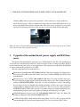
Figura 7: View of the lower plate where the main CPU board sits. New separators were installed where
it indicated with blue circles. They serve to screw the two processors and its heatsinks. The empty holes
indicate the separators used by the previous motherboard and now no longer necessary. The steps on the
right and left sides of the plate are used to attach this plate to the lower part of the Mark5B rack.
Prior to unplugging the eight flat cables from the Streamstor board and the chassis backplane, we tagged each flat cable with a water proof pen. Usually each cable has associated an
increasing consecutive number. We also took some photographs to spot where and how the cables were plugged on each board. In order to extract the board it is necessary to remove the hard
disk and its aluminium support first.
The old board was unscrewed and removed from its lower plate. The lower plate is attached
to the lower part of the rack and stands ∼1 cm above it. The right and left borders have a step
which is used as holder for the eight screws that fix it to the rack. This plate was unscrewed
3
UPGRADE OF THE MOTHERBOARD, POWER SUPPLY AND RAM MEMORY
9
and taken out to remove the aluminium separators that are not needed and to mount new ones
where the new plate requires them. In order not to bend the plate when pressing the processors
on top of sockets, the board comes with a rubber bump that we cut to reduce its height so that it
matched the height of the aluminium separators. There is an empty space in the board specially
prepared for this aim. The new screws fix the board to the plate at 8 different places. There are
also 8 more separators and screws used to fix the two processors with its heatsinks and fans to
the plate. The separators have metric size. Figure 7 shows the new holes where the separators
were placed.
Finally the heatsinks together with the fans were installed on top of the processors. It was
necesary to cut the springs and push them strongly to get a good contact between them and the
processors. Figure 8 shows the mounting process on one shot.
Figura 8: Mounting the heatsinks. Image taken from the manufacturer.
Once the board was screwed on to the plate, the aluminium plate that surrounds the IO
connectors (ethernet, VGA, USB, RS232 ...) was mounted. On its inner face we mounted an
adhesive soft foil which acts as an electromagnetic screen. The soft side is towards the inner
side of the box. The lower plate together with the main board were inserted into the rack. Since
the space is very narrow it was necessary to dismount the rear part of the rack and tilt it partially
towards the outside. Once the board and its supporting plate were on place the rear part of the
rack was screwed again. The lower plate was screwed to the bottom of the rack. This is a difficult
operation since the plate covers part of the holes and there is hardly space for a screwdriver.
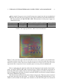
The cables from the reset button, the power LED and the power switch were connected to the
Front Pannel Header connector on the board. See figure 9 for the schematics of the connector
and its location on the motherboard. Table 2 summarizes the connections. Cables were fitted
3
UPGRADE OF THE MOTHERBOARD, POWER SUPPLY AND RAM MEMORY
10
Figura 9: Schematics of the motherboard. Image taken from the manufacturer.
Figura 10: Power supply schematics showing the available sockets. Image taken from the manufacturer.
3
UPGRADE OF THE MOTHERBOARD, POWER SUPPLY AND RAM MEMORY
11
together with plastic ties on adhesive mounts on the wall of the rack.
Signal Pair Red wire
Power LED
Pin 1
Power Switch Pin 11
Reset Switch Pin 15
Black wire
Pin 5
Pin 13
Pin 17
Cuadro 2: Connections in the Front Pannel Header connector of the motherboard.
The StreamStor board was inserted into the PCI-X 133 Slot and then we connected the 8 flat
cables from the Mark5 chassis backplane. Later, the Mark 5A I/O interface board was inserted
into the PCI Slot 32/33. See Figure 9 to see where the PCI slots are located on the motherboard.
In the new board the distance between the two slots is larger than in the old board, since in
between there are two PCI Express slots. This required to use a longer FPDP cable from the
StreamStore board to connector J1 on the Mark5 I/O interface board. Finally cables to the Mark5
I/O interface board were connected acording to the instructions on section 2 of this report.
The power supply was replaced by a new one with the same dimensions. The new power
supply provides plenty of cables and connectors. On one of its faces it has a number of connectors (see figure 10). Table 3 summarizes the conexions for each output.
The green connector on the Mark5 chassis backplane provides power for the Mark5 disk
packs. It has three inputs for +12 V, one input for +5 V and three inputs for ground. To provide
the maximum power every pin gets two wires from 2 different outputs of the power supply. We
have used red cables for +5 V and green ones for +12 V, following the same convention as the
power supply manufacturer.
Power Supply output
FAN
HDD
MB
HDD
PB
HDD
HDD
PCIE4
PCIE3
PCIE2
PCIE1
Common
Target
Connector
—
Hard Disk
—
DVD
motherboard
8 pin +12 V
Chasis Backplane Green connector +5 V
Chasis Backplane Green connector +5 V
Chasis Backplane Green connector 3 x +12 V
Chasis Backplane Green connector 3 x +12 V
—
—
motherboard
24 pin +5 V
Cuadro 3: Connections from the power supply. They are listed downwards (left to right) (left to right)
(left to right) (left to right) (left to right) (left to right) (left to right) (left to right) to upwards as seen on
the lateral face of the power supply. All conections to the chassis backplane connector were done using
plain cables without end connectors.
4
UPGRADE OF THE MARK5 OS AND SOFTWARE
12
The final task was to replace the CD by a DVD. The data cable is an IDE that goes to its
socket on the motherboard (see schematics on Figure 9 to spot its location). The support tray
for the hard disk was installed and a SATA 2 disk was screwed on top of it. The data cable was
inserted in the SATA A1 connector in the motherboard.
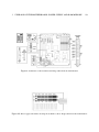
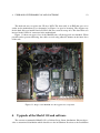
Figure 11 shows an upper view of the Mark5B once all the upgrade was finished. When
possible and to prevent cluttering, the cables are tied using adhesive mounts on the inner faces
of the rack.
Figura 11: Image of the Mark5B once the upgrade was completed.
4.
Upgrade of the Mark5 OS and software
The current recommended Mark5 OS is a Debian Sarge Linux distribution. Haystack provides a customized distribution which should ease the installation. Previous to the installation
4
UPGRADE OF THE MARK5 OS AND SOFTWARE
13
some work had to be performed with the PC BIOS. First the clock was set to UTC from the
BIOS menu.
Once this was set up we booted the Mark5B from a CD which contains the Mark5B OS
system for Debian Sarge. The default BIOS setup follows this boot order and takes some time
to perform each step:
1. Intel BIOS Boot. Takes 20 seconds. During this time if F2 is pressed it is possible to enter
the BIOS
2. Yukon PXE. In this phase the PC delays for 15 seconds.
3. Ethernet GE boot. The PC tries to boot from the network and spends 45 seconds here.
4. EFI boot manager. It takes 10 seconds to complete this step. Then the procedure waits
for the operator to select an option from a list. In order to boot from the CD one should
choose: “Legacy Boot”.
Installation was performed using two CDs obtained at the TWG meeting in Haystack during
the first week of May 2007 and following the instructions published in
http://www.haystack.mit.edu/tech/vlbi/mark5/downloads/Upgrade_notes_a.pdf.
The automatic installation procedure did not complete successfully, possibly because it uses a
route to the stable Debian version (now ”Etch” instead of Sarge) for security updates which
breaks the process. When the procedure requests a method for Apt, it is necessary to insert CD
number 2 into the DVD and select CD in the menu list. The procedure will connect to Internet
to retrieve the updated packages from the security repository and this will fail. To overcome
this situation it is necessary to enter aptitude type U, u, and g. This sequence of keystrokes will download some packages and install them. The locales package will be installed
and will request the selection of an environment. We chose es_ES@euro. From this item
it is necessary to perform manually the installation of exim. Once the procedure finishes, file
/etc/apt/sources.list should be changed replacing ”stable” by ”sarge”. Then it is necessary to use aptitude and update the list of packages (type keystroke U), upgrade (type keystroke
u) and install new packages (type keystroke g).
The installation of the X-Window system does not complete sucessfully either. To complete
it, select packages x-window-system-core and xterm and install them. In order to have
a window environment file /etc/apt/sources.list should be modified previously to use
repositories in Internet. If not the only available window manager is twm. We changed the
repositories and installed KDE.
There are newer CDs at the Haystack FTP which might solve the problems described in the
two previous paragraphs.
The linux kernel by default installed is 2.4.27-3-386, but we updated to 2.4.27-3-686 which
is better suited for the installed processors.
Once the OS installation was complete and in order to reduce the boot time and to make
the boot automatic without the assistance of a human operator, the boot order was modified. By
default the system tries to boot from the PXE, the network, the hard disk and finally the CD or
DVD. The boot order was modified according to this list:
4
UPGRADE OF THE MARK5 OS AND SOFTWARE
14
1. 3M-WDC WD800JD-60J.
2. PM TEAC DV-W516GC.
3. IBA GE Slot 0720 V.
4. B5 D0 Yukon PXE.
5. EFI Boot manager.
Mark5B software is installed by running from root script MakeMark5 which is not available
at Haystack FTP and therefore is included as an appendix at the end of this report. This script
creates oper and jball accounts, its .cshrc and .login files, forces usage of tcsh, compiles all
control programs and installs them.
To fully complete the installation it is necessary to create the mk5b kernel module. This requires changing line 2 from file /usr/local/mk5b-intr/src/ccm with the adequate kernel
headers. In our case the line was:
gcc -c -Wall -O2 -g -DMK5B_DEBUG -I/usr/src/kernel-headers-2.4.27-3-686/include mk5b.c &
and run the following commands
cd /usr/local/mark5-intr/src
./ccm
mk5breg
This module should be loaded each time the Mark5B is booted. If not the Mark5B program
will not start correctly. Correct load of the module should produce the following log, which can
be easily inspected using dmesg:
mk5b:
mk5b:
mk5b:
mk5b:
mk5b:
irq = 18
memory page: 0xf6be6000
dim id is 5b80
registered module, major=253
version 1.0 (compiled on Oct 31 2007) loaded
Finally we tested the software by running Mark5B:
Mark5B &
Mark5B
Mark5B
Mark5B
Mark5B
inBoard() ERROR: XLRSetDBMode() returned error
inBoard() ERROR: XLRSetDBMode() returned error
inBoard() ERROR: XLRSetDBMode() returned error
Ready. End with EndM5B, please
If debugging is required, Mark5B should be run with the following params:
Mark5B -m0 -f0 &
Troubleshoot notes:
5
APPENDIX
15
If the Mark5b is rebooted the modules will not be loaded and the Mark5b will fail to be
operated correctly.
The MakeMark5 script creates file /etc/rc.local which intends to load the streamstor
and mk5b kernel modules on boot. This solution, however, does not work in Debian and
should be installed this way:
cp /etc/rc.local /etc/init.d/mark5bInit
update-rc.d mark5bInit start 98 S . stop 98 0 6 .
After running update-rc links in directories /etc/rcS.d, /etc/rc0.d and /etc/rc6.d
will be created.
All Mark5b programs require the oper account to run using a tcsh shell and not a bash
one. Typically ssopen will fail and Mark5b will exit complaining about being unable to
open a file if using a bash shell.
It is absolutely necessary that .login is executed always when loging into the oper
account, however this does not happen if one opens a konsole and several tabs. To avoid
this problem .login can be sourced from .cshrc like this:
source .login
.login provides the correct environment variables and PATH for the Mark5b control
programs under tcsh.
When Mark5b is executed previous to ssopen startup, the program will take 1 minute to
fully start. ssopen also needs 1 minute to complete.
When the Mark5b program is being executed and the VSI input is correctly connected to
the VSI4 sampler module, the 1 PPS red light blinks once per second. This is not an error
and indicates that the system is receiving 1 PPS from the VSI source.
5.
Appendix
#!/bin/bash
# MakeMark5
# Starting from generic Linux, make a Mark-5 software installation.
# This must be executed by root. And you’ll need Internet access
# to Haystack to download the tarball.
# This version should work on either RedHat or Ubuntu.
# (Remember bash, not tcsh.) Revised: 2005 May 26, JAB
#
# Debug pause after each line:
# function pause { echo -n "." ; read ; }
# trap pause DEBUG
5
APPENDIX
#
echo " Check: Must be root: "
if [ ‘ id -u ‘ != 0 ] ; then
echo " You must be root to run MakeMark5. Sorry. "
exit -1
fi
#
echo " Making a login for oper: "
/usr/sbin/useradd -m -p ’$1$pFgccZGg$zgsSQUL3qA6Cpba0PwUD70’ \
-g users -s /bin/tcsh oper
chmod 0755 ~oper
#
echo " Making a login for jball: "
/usr/sbin/useradd -m -p ’$1$NGfJHjfD$Rp9Fj8ub9ZNO9SK23gMs6/’ \
-g users -u 501 -s /bin/tcsh jball
chmod 0755 ~jball
#
echo " Creating the following directories: "
mkdir -v -m 0755 /home/streamstor
mkdir -v -m 0755 ~jball/bin
mkdir -v -m 0755 ~jball/C
mkdir -v -m 0755 ~jball/F
mkdir -v -m 0755 ~jball/Mark5
mkdir -v -m 0755 /var/dir
#
echo " Creating file /var/dir/Mark5A: "
cd /var/dir
touch Mark5A
chmod 0644 Mark5A
#
echo " Creating the following symbolic links: "
cd /home/streamstor
ln -s linux Sdk
cd ~oper
ln -s ~jball/bin
.
ln -s ~jball/C
.
ln -s ~jball/F
.
ln -s ~jball/Mark5 .
cd ~jball/C
ln -s /home/streamstor/Sdk/include/sc_api.h
.
ln -s /home/streamstor/Sdk/include/xlrapi.h
.
ln -s /home/streamstor/Sdk/include/xlrtypes.h .
ln -s /home/streamstor/Sdk/lib/libssapi.a
.
cd ~jball/bin
ln -s /home/streamstor/Sdk/util/sslog
.
ln -s /home/streamstor/Sdk/util/ssflash .
ln -s /home/streamstor/Sdk/util/ssopen .
16
5
APPENDIX
17
ln -s /home/streamstor/Sdk/util/sstest .
#
echo " Copying the following .chsrc file into both ~oper and ~jball: "
cat << ’..End..’ > ~oper/.cshrc
#
# Generic .cshrc
# This version for Linux
# Revised: 2002 February 21, JAB
# setenv HZ 100
alias wh who /var/log/wtmp
alias www cd /home/httpd/html
alias tq /usr/sbin/ntpq -p
# The stuff prior to this line should get executed on
# remote shell from some other computer.
if ( $?prompt == 0 ) exit
echo "csh on ‘hostname‘ (‘uname‘) is executing $HOME/.cshrc "
unset autologout
# echo HZ is $HZ
echo PATH is $PATH
# set hname = $HOST:r
# set hn = $hname:r
# unset hname
set hname = ‘ hostname ‘
set dname = .‘ dnsdomainname ‘
set hn = ‘ basename $hname $dname ‘
unset hname dname
if ( $?LOGNAME == 1 ) then
set prompt = "$LOGNAME@${hn}[\!]% "
else if ( $?USER == 1 ) then
set prompt = "$USER@${hn}[\!]% "
else
set prompt = "‘whoami‘@‘hostname‘[\!]% "
endif
stty erase "^?" ; echo "erase set to ^? "
set history = 15 ; echo history set to $history
set cdpath = ~ ; echo cdpath set to $cdpath
echo Working directory is ‘pwd‘
date ’+
%Y %B %d (%A) %R %Z’
echo " "
..End..
cp ~oper/.cshrc ~jball/.cshrc
#
echo " Copying the following .login file to both ~oper and ~jball: "
cat << ’...End...’ > ~oper/.login
#
# Generic .login revised: 2002 May 20, JAB
5
APPENDIX
# This version for Linux.
# source /etc/cshrc
echo "csh on ‘ hostname ‘ (‘uname‘) is executing $HOME/.login "
# ‘hostname‘ doesn’t seem to work on gauss
echo "tty is: " ‘ tty ‘
if ( $?TERM == 1 ) then
echo "TERM is $TERM (but may be changed below)"
endif
setenv PATH :$HOME/bin:/bin:/usr/bin:/usr/local/bin:/usr/bin/X11
if ( ‘ tty ‘ == ’/dev/console’ ) then
# setenv PATH $PATH’:/usr/bin/X11’
setenv DISPLAY ‘ hostname ‘:0 ; echo DISPLAY set to $DISPLAY
setenv TERM AT386-M
else if ( $?TERM == 0 ) then
setenv TERM vt100
else if ( $TERM == ’unknown’ ) then
setenv TERM vt100
endif
set term = $TERM
# setenv MANPATH /usr/share/man:/usr/local/man
# setenv PAGER "more -s"
setenv PAGER "less -s"
setenv NNTPSERVER news.mit.edu
setenv STREAMSTOR_BIB_PATH /home/streamstor/Sdk/bib
setenv SS /home/streamstor/Sdk
tput init
echo "tput longname is: " ‘ tput longname ‘
stty kill "^X" ; echo Kill set to control-X
stty intr "^C" ; echo Intr set to control-C
stty echoe ; echo Echoe set on
echo PATH set to $PATH
ps -l ; w
echo HOME is $HOME ... Directory of ‘ pwd ‘ is:
ls -al
date ’+
%Y %B %d (%A) %R %Z’
...End...
chown -R oper.users ~oper
cp ~oper/.login ~jball/.login
chown -R jball.users ~jball
#
echo " Appending the following onto /etc/services: "
cd /etc
mv services services.dist
cat services.dist - << ’....End....’ > services
# Local services
m4crate
2600/tcp
# Mark-4 Crates
18
5
APPENDIX
m4crate
m4taplib
m4taplib
m5drive
m5drive
m5data
m5data
m4msgd
m4msgd
19
2600/udp
2610/tcp
2610/udp
2620/tcp
2620/udp
2630/tcp
2630/udp
2680/tcp
2680/udp
#
#
#
#
#
#
#
#
#
Mark-4
Mark-4
Mark-4
Mark-5
Mark-5
Mark-5
Mark-5
Mark-4
Mark-4
Crates
Tape Library
Tape Library
Drives
Drives
Data
Data
Messaging
Messaging
....End....
chmod --reference=services.dist services
#
echo " Appending the following onto rc.local: "
cd /etc
if [ -d rc.d ] ; then
cd rc.d
fi
# (On Ubuntu, there is no rc.d directory, but that’s OK)
if [ ! " -a rc.local " ] ; then
# No rc.local, so make one:
echo "#!/bin/bash " > rc.local
chmod 0755 rc.local
fi
mv -f rc.local rc.local.dist
cat rc.local.dist - << ’.....End.....’ > rc.local
#
# Added 2002 February 5, JAB:
echo "Loading module windrvr6 for StreamStor "
# /home/streamstor/Sdk/driver/wdreg /lib/modules/misc/windrvr.o
/sbin/insmod windrvr6
chmod 0666 /dev/windrvr6
chmod 0666 /dev/ttyS0
# Revised 2003 July 09, JAB:
echo "Setting the clock from NTP "
/usr/sbin/ntpdate -b -p 8 -u gauss
.....End.....
chmod 0755 rc.local
#
echo " Reseting time daily using cron: "
cd /etc/cron.daily
echo "#!/bin/bash" > ntpdate
echo "/usr/sbin/ntpdate -b -p 8 -u gauss " >> ntpdate
chmod 0755 ntpdate
#
echo " Creating /etc/hardware_id (with dummy contents): "
5
APPENDIX
20
cd /etc
echo "mark5-XX" > hardware_id
chmod 0444 hardware_id
#
echo " Downloading the Mark-5 tarball from Haystack into /tmp: "
cd /tmp
rm -f Mark5A.tar.gz
rm -f Mark5A.tgz
# /usr/bin/ncftpget ftp://web.haystack.edu/dist/mark5/Mark5A.tgz
/usr/bin/wget ftp://web.haystack.edu/dist/mark5/Mark5A.tgz
if [ $? != 0 ] ; then
echo " Some ERROR. You must have Internet access to Haystack. Sorry. "
exit -2
fi
echo " Unzipping and untarring this tarball: "
/bin/tar xzvpP --same-owner -f Mark5A.tgz
if [ $? != 0 ] ; then
echo " Some ERROR. Something must be done about this. "
exit -3
fi
echo " Doing a Jungo driver re-installation: "
cd /home/streamstor/linux/driver/redist
rm -fr LINUX*
./configure
make clean
make
make install
if [ $? != 0 ] ; then
echo " ERROR: The Jungo driver re-installation seems to have failed. "
exit -4
fi
echo " (You may ignore the warning about \"will taint the kernel\") "
chmod 0666 /dev/windrvr6
echo " Recompile all Mark-5-associated programs: "
cd ~jball/bin
./cc5A
echo " ##### Now check for any errors noted above ##### "
echo " The following manual operations remain to be done: "
echo " Substitute a local NTP server instead of gauss in the last lines of "
echo " /etc/rc.d/rc.local or /etc/rc.local and /etc/cron.daily/ntpdate . "
echo " Write this machine’s official name (i.e., mark5-nn) into "
echo " /etc/hardware_id (e.g., \"echo mark5-nn > /etc/hardware_id\"). "
echo " Change the root password to match this machine’s official name. "
echo " If you don’t have any error messages, then Mark5A should be ready. "
echo " Logout as root and login as oper (!), "
echo " and then run the prescribed suite of tests on this machine. "
REFERENCIAS
Referencias
[1] Aldrich W., Haystack Obs. Mark5 Memo, 2006
[2] BQT-P6-PRO User Manual, 2007
[3] Intel Server Boards SE7520BD2VD2. Fast mounting instructions, 2007
[4] MCX-VPro Heatsink. Mounting instructions, 2007
21