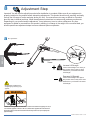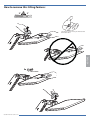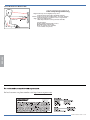
1
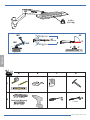
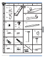
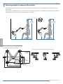
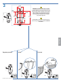
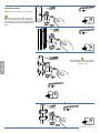
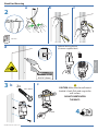
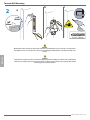
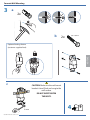
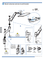
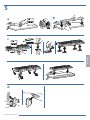
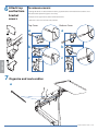
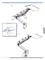
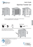
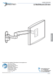
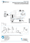
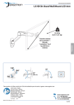
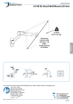
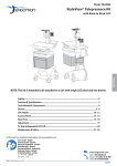
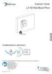
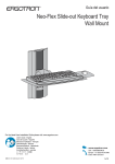
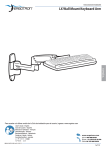
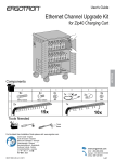
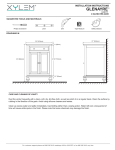
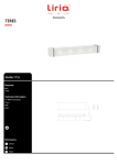
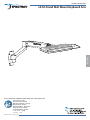
ASSEMBLY INSTRUCTIONS
LX Sit-Stand Wall Mount Keyboard Arm
ENGLISH
For the latest User Installation Guide please visit: www.ergotron.com
User's Guide - English
Guía del usuario - Español
Manuel de l’utilisateur - Français
Gebruikersgids - Deutsch
Benutzerhandbuch - Nederlands
Guida per l’utente - Italiano
Användarhandbok - svenska
ユーザーガイド : 日本語
用户指南 : 汉语
888-45-276-W-02 rev.G • 01/15
1 of 16
0-5 lbs
(0-2.3 kg)
180°
90°
20"
(508 mm)
180°
5°
360°
3°
ENGLISH
3°
A
B
C
D
2
1
1
Stud Finder
Concrete Wall Mounting
Ø 3/8” (10mm)
2
Wood Stud Mounting
13 mm
Ø 3/16" (5mm)
888-45-276-W-02 rev.G • 01/15
2 of 16
A
B
C
1x
1x
D
1x
1
1x
1x
1x
2
1x
2x
2x
2x
2x
3
1x
M6
ENGLISH
M6 x 45mm
4x
4x
1x
1x
4
10-24 x 1/2"
M4 x 8mm
2x
2x
1x
M8
5
5mm
M8 x 80mm
2x
2x
6
M4 x 14mm
4mm
4x
2x
1x
1/8”
888-45-276-W-02 rev.G • 01/15
3 of 16
1
Mounting Height for Ergonomic Workstation
This mounting height is a recommendation for an ergonomic workstation that accommodates user heights of 5’0”-5’9”
(152-175cm).
If user heights are different than this, you should change mounting height to accommodate user heights. (Change mounting height one inch for every one inch difference in user heights).
5’0” - 5’9”
(152-175cm)
5’0” - 5’9”
(152-175cm)
28”
(711mm)
ENGLISH
23”
(584mm)
Determine mounting location:
Front view with arm pushed back against the wall.
Top view showing range of motion when pulled out from the wall.
20.3”
(516mm)
22”
(562mm)
0.2”
(4.7mm)
1.3”
(32mm)
10.2”
(259mm)
4.2”
(106mm)
27.6”
(701mm)
888-45-276-W-02 rev.G • 01/15
4 of 16
2
3.15"
(80mm)
1.57"
(40mm)
1.34"
(34mm)
1.14"
(29mm)
6.5"
7.1"
(165mm)
WARNING: Ensure that the wall structure is capable
of supporting four times the total weight of mounted
equipment. Mounting to wall surfaces that do not meet
this criteria may result in an unstable, unsafe condition
which could lead to personal injury and/or property
damage. Consult a construction professional if you
have any doubt about what this means in regard to
your particular application.
(180mm)
5.1"
(129mm)
CAUTION: Make sure the wall mount bracket is level,
flush and snug to the wall surface. DO NOT OVERTIGHTEN THE BOLTS.
ENGLISH
Ergotron product
Wood
6
Concrete
7
8
888-45-276-W-02 rev.G • 01/15
5 of 16
Ergotron product
4x
10-24 x 1/2"
NOTE: Wall Track and Brackets sold separately.
1/8"
9
NOTE: Fasteners may unwind due to vibration caused by movement of mounting solution over time. Inspect mounting solution
for loose fasteners on a routine basis. If desired, apply a light duty
thread locking adhesive to fasteners before installation to prevent
back-out.
4x
10-24 x 1/2"
1/8"
9
10-24 x 5/8"
ENGLISH
4x
When attaching to Pole Clamps, use 10-24 x 5/8”
screws included with pole brackets, Do NOT use
10-24 x 1/2” screws
1/8"
9
4x
10-24 x 1/2"
1/8"
9
888-45-276-W-02 rev.G • 01/15
6 of 16
Wood Stud Mounting
a
b
c
2
Stud Finder
d
Optional locking feature
(customer supplied lock)
2.75”
ENGLISH
Ø 3/16" (5mm)
3b
c
2x
CAUTION: Make sure the wall mount
bracket is level, flush and snug to the
wall surface.
M8 x 80mm
DO NOT OVERTIGHTEN
THE BOLTS.
13 mm
4
9
888-45-276-W-02 rev.G • 01/15
7 of 16
Concrete Wall Mounting
2
a
b
c
3-1/8"
(80 mm)
Ø 3/8” (10mm)
ENGLISH
WARNING:
Mounting holes must be at least 3-1/8” (80mm) deep and must be located within solid concrete, not mortar or covering material.
If you drill into an area of concrete that is not solid, reposition mounting holes until both anchors can be fully inserted into solid
concrete!
WARNING:
Anchors that are not fully set in solid concrete will not support the applied load resulting in an unstable, unsafe condition which
could lead to personal injury and/or property damage. Consult a construction professional if you have any doubt about what this
means in regard to your particular situation.
888-45-276-W-02 rev.G • 01/15
8 of 16
Concrete Wall Mounting
3
a
2x
x
b
M8 x 80mm
2x
Optional locking feature
(customer supplied lock)
ENGLISH
c
CAUTION: Make sure the wall mount
bracket is level, flush and snug to the
wall surface.
DO NOT OVERTIGHTEN
THE BOLTS.
13 mm
4
9
888-45-276-W-02 rev.G • 01/15
9 of 16
4 Mount extension and arm to wall bracket.
4x
c
M4 x 8mm
ENGLISH
b
Do Not
Overtighten
Cap Screw!
M6
M6 x 45mm
M6
4mm
M6 x 45mm
a
NOTE: when
sliding sleeve
on to bracket,
align slot over
rotation stop.
Do Not
Overtighten
Cap Screw!
4mm
Top View
+
Rotation Stop
on Bracket
=
Slot
in Sleeve
Sleeve on
Bracket
888-45-276-W-02 rev.G • 01/15
10 of 16
5
b
a
c
4x
ENGLISH
d
888-45-276-W-02 rev.G • 01/15
11 of 16
top
6 Attach
and bottom
bracket
covers
To remove covers:
a) Wedge the blade of a flat screwdriver into the gap between the wall mount bracket and the cover.
Rotate the blade upward to pry the cover away.
b) Repeat on the opposite side of the wall mount bracket.
c) Once the cover is free on both sides, lift it off.
Top Cover
Bottom Cover
a
b
b
c
c
ENGLISH
a
7 Organize and route cables
a
888-45-276-W-02 rev.G • 01/15
12 of 16
b
Leave Slack in cable
ENGLISH
c
888-45-276-W-02 rev.G • 01/15
13 of 16
8
Adjustment Step
Important! You will need to adjust this product after installation is complete. Make sure all your equipment is
properly installed on the product before attempting adjustments. This product should move smoothly and easily
through the full range of motion and stay where you set it. If movements are too easy or difficult or if product
does not stay in desired positions, follow the adjustment instructions to create smooth and easy movements.
Depending on your product and the adjustment, it may take many turns to notice a difference. Any time
equipment is added or removed from this product, resulting in a change in the weight of the mounted load, you
should repeat these adjustment steps to ensure safe and optimum operation.
a
Lift – Up and down
ENGLISH
5mm
5mm
Increase Lift Strength
If the mounted weight is too heavy or
this product does not stay up when
raised, then you'll need to increase
Lift Strength:
Decrease Lift Strength
If the mounted weight is too light or
this product does not stay down when
lowered, then you'll need to decrease
Lift Strength:
CAUTION: DO NOT overtighten fasteners.
Overtightening may cause damage to your
equipment.
WARNING
WARNING! Stored Energy Hazard: The arm mechanism is under tension and will move up rapidly, on its own, as
soon as attached equipment is removed. For this reason, DO NOT remove equipment unless the arm has been
moved to the highest position! Failure to follow this instruction may result in serious personal injury and/or
equipment damage!
888-45-276-W-02 rev.G • 01/15
14 of 16
How to remove this tilting feature:
3°
3°
Save these screws incase you want to add
this feature later.
ENGLISH
2x
M4 x 14mm
888-45-276-W-02 rev.G • 01/15
15 of 16
Set Your Workstation to Work For YOU!
Learn more about ergonomic computer use at:
www.computingcomfort.org
Height Position top of screen slightly below eye level.
Position keyboard at about elbow height with wrists flat.
Distance Position screen an arm's length from face—at least 20” (508mm).
Position keyboard close enough to create a 90˚ angle in elbow.
Angle Tilt screen to eliminate glare.
Tilt the keyboard back 10° so that your wrists remain flat.
ENGLISH
To Reduce Fatigue
Breathe - Breathe deeply through your nose.
Blink - Blink often to avoid dry eyes.
Break • 2 to 3 minutes every 20 minutes
• 15 to 20 minutes every 2 hours.
For local customer care phone numbers visit: http://contact.ergotron.com
© 2015 Ergotron, Inc.
888-45-276-W-02 rev.G • 01/15
16 of 16