1
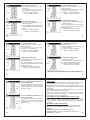
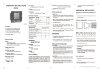
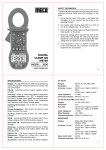
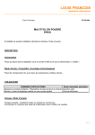
Index ® Page MULTIFUNCTION POWER & ENERGY MONITOR WITH MODBUS RTU PROTOCAL MODEL : MFM-96UMT/UE MFM-96U POWER & ENERGY MONITOR Installation and User Manual l Introduction & Safety Recommendations l Technical Specifications 04-05 l Processing Method 06-09 l Key Pads 10-15 l Mechanical Dimensions l Display Indication 17-19 l Page Sequence Diagram 20-21 l Connection Diagrams 22-23 l Sequence Display Page 24-34 l Serial Output l RS 485 / RS 232 Interface Connection l General Warranty Certificate Technical Specifications Display For MFM96UE MD & THD features not available Weight 40 Key Pads Measuring Interval Operating Temp., Humidity Dimension (mm) : 4 Rows of 4 digit RED LED display For Energy Measurement 8 Digit 00000000 ~ 99999999 x 105 LED Display Height 9.2mm / 0.36” : 4 function keys to scroll through display pages and to set programming parameters. : 0.5 sec : 0°C to 50°C : <90% RH (Non Condensing) : Front 96 x 96 mm Depth (Behind Bezel) 60 mm Panel Cutout 92 x 92 mm : 490 gms. (approx) Electrical Specifications Safety Recomendations To guarantee the level of safety incorporated in the device, follow the instructions below : 1) Adhere strictly to the connection diagrams for the installation of the instrument. 2) Before gaining access to the terminal, ensure that the conductors to be connected to the instrument are not live. 3) Make sure that the electrical panel in which the instrument is to be placed is designed in such a way as to guarantee that the terminals are inaccessible after installation. 3 Voltage Input Nominal Measurement Max. Range Burden Accuracy Range PT Ratio : : : : : : Current Input Nominal Measurement Range Burden Max. Current Accuracy Range CT Ratio : : 5A AC (Line) isolated 1A AC (against specific order) : 1 ~ 6A AC Max : < 0.1VA / Phase : 200% for 1 sec. (10A max.) : 20 ~ 120% : Use CT for higher input ranges. CT Ratio Fully Programmable (1.000 ~ 9999) : CTR, PTR, Configuration setting, Password, peak demand period (minute), Auto Scroll, Instrument address (000~247) : : : : : : : : 36-38 2 MFM-96UMT/UE universal Multifunction Meter is a microcontroller based electrical analyzer indicating TRMS values of Various electrical parameters. It mesures 68 parameters & displays on 22 display pages each page has matrix 4 rows of LED display of 4 digit each. It features user programmable function such as Password Protection, CT Ratio, PT Ratio, Meter configuration setting, Instrument address, MD Period, Auto scroll & Energy Erase facility. It is equipped with a 4 key keypad for scrolling through display pages & to set the programmable function. Accuracy : Voltage Current Active Power Reactive Power Apparent Power Power Factor Energy Frequency 16 35 Introduction Programmable Parameters 03 for 3P 3W 110V AC / 440V AC (Phase - Phase) 150V ~ 530V AC (Phase - Phase) < 0.3 VA / Phase 20% ~ 120% Use PT for higher input ranges. PT Ratio Fully Programmable (1.000 ~ 9999) ± 0.2% of Full Scale ± 0.2% of Full Scale ± 0.5% (CosF = 0.3 to 1.00) of Full Scale ± 1% (SinF = 0.3 to 1.000) of Full Scale ± 0.5% of Full Scale ± 1° Electrical Class 1 5 ± 0.2Hz (45 ~ 65Hz) System : 3 Phase 3 Element 4 Wire Factory Set : 3 Phase 2 Element 3 Wire Auxiliary Power Supply : Nominal (Range) : 230V AC (185~264V AC) 110V AC (90~126V AC) optional Frequency : 50Hz Burden : < 5 VA Voltage Input : for 3P 4W Nominal : 230V / 240V AC (Phase - Neutral) Measurement 400V / 440V AC (Phase - Phase) Max. Range : 300V AC Max. (Phase - Neutral) 4 520V AC (Phase - Phase) } Processing method - for 3 Phase 3 Element 4 Wire a) Phase Values : Effective phase voltage N S [V i=1 Vn (TRMS) = n N N Effective phase current ( i)] 2 S[I n (i)] 2 i=1 I n (TRMS) = N N SV ( )In(i) n i i=1 Active phase power Pn = Apparent phase power S n = V n(TRMS) Reactive phase power Qn = Phase power Factor PFn = 6 MFM96UMT-UE : 28-09-2012 N X I n(TRMS) S n2 - P n 2 Pn Sn Processing method - for 3 Phase 2 Element 3 Wire b) Equivalent system Values : a) Phase Values : Equivalent system voltage N Effective phase voltage Vn (TRMS) = S [V n N Equivalent system current N System active power Effective phase current System reactive power System apparent power Equivalent system power factor 7 S[I n (i)] 2 i=1 N Active power - first phase P1 = VRY x IR x Cos (30 + F) Active power - third phase P3 = VYB x IB x Cos (30 - F) Reactive power - first phase Q1 = VRY x IR x Sin ( F + 30) Reactive power - third phase Q3 = VYB x IB x Sin ( F - 30) PF phase 1 PF1 = Cos (30 + F) PF phase 3 8 PF3 = Cos (30 - F) Key Pad b) Equivalent System Values : The key Pad contains 4 keys with the following functions in normal operation. Equivalent system voltage Equivalent system current System active power I n (TRMS) = (i)] 2 i=1 pk Optional for Max. Demand page t t Down “ t ” is used to move to next page. T “ T ” is used to move to first (system) page. Up “ s ” is used to move previous page. PT = P1 + P3 Operating Modes System reactive power QT = Q1 + Q3 System apparent power ST = S1 + S3 Parameter setting mode (Programming mode) : This mode can be invoked by pressing “s” & “t” keys simultaneously at power on. In this mode eight pages are available for settings, namely Password Protection, CT ratio, PT ratio, Meter configuration setting, Instrument address, MD period, Auto Scroll Mode & Energy Erase mode of Instrument. A) Password Protection : Equivalent system power factor The first screen appears after entering in Parameter Setting Mode is Enter Password. It ask the user to enter password to change the parameter settings. 9 10 The user should first enter 9999 (MECO Passward) If password is correct “ pk ” key is pressed again then change password screen appears. The user should enter correct password by using “s” & “t” keys. The “t” key is used to enter the digits (0 to 9) & “s” key is used to shift the digit position (Right to Left). If the user wants to change passward then should press “ pk ” key to select (yes). If he don’t want to change passward than he should press “ T ” key. After entering the passward, press “pk” key to confirm it. If is selected then new password screen appears. If the entered passward is wrong an error message appears on screen. 11 The user may select new passward by using “s ” & “t ” key overwrite on existing passward. After overwritting new passward he should press press “pk” key to confirm it. 12 MFM96UMT-UE : 28-09-2012 B-1 On pressing “pk” key password is stored & CT ratio setting page is displayed. It user select (no) for password change then meter directly scrolls to CTR screen. B) CT ratio setting page : CT ratio is set by using “s”, “t” & “T’’ keys. The digit to be incremented is selected by pressing “s” key. The selected digit can be incremented using “t” key. to fourth digit. On pressing “ pk ” key, PT ratio is stored and configuration setting page is displayed. D) Configuration setting page : For setting configuration 3E/2E press “t” key. On pressing “ pk ” key, the configuration setting is stored & Instrument address setting page is displayed. Decimal point position is shifted by pressing “T” key. Shifting of decimal point from first to fourth digit, On pressing “pk” key, CT ratio is stored and PT ratio setting page is displayed. E) Network address setting page : Instrument address is set using “s” & “t” keys. The digit that is to be incremented is selected by pressing “s” key. The selected digit can be incremented by pressing “t” key. On pressing “pk” key, instrument address is stored & Peak Demand Period page is displayed. C) PT ratio setting page : Display Indication 1) Numerical Field Zone This consists of four rows of four digits each. The first row indicates measurement for phase 1, second row indicates measurement for phase 2(0000 for 3P2E3W), third row indicates measurement for phase 3 & fourth row indicates measurement for the whole system except system page. 2) Customised Symbol Zone This zone backs up the numerical indications and is used to give a “clear” indication of the type of measurement being taken. VL-N = Line to Neutral Voltage in VAC VL-L = Line to Line voltage in VAC 17 Mechanical Diamensions (mm) Model : MFM-96UMT/UE 96.0 t t F) Peak demand period page : Peak demand period is set by using “s”, “t” keys. The digit to be incremented is selected by “s” key. The selected digit is incremented by “t” key on pressing “pk” key peak demand period is stored and Auto mode is displayed. G) Auto mode : The user may choose Factory selected Auto interval for Auto scrolling of the parameter pages. If the user wants to enter the Auto scroll mode then he should press “pk” key. When the input is applied the meter runs in Autoscroll mode. If the user wants to use Manual scroll, then he should press “T” key to deselect Autoscroll mode & then “pk” key to confirm. When “pk” or “T” key is pressed instrument switches to Energy erase mode. H) Energy Erase mode : The user may erase the stored energy in the meter. If user wants to erase the energy he should press “pk” key. If user does not want to erase the energy he should press “T” key. When “pk” key is pressed instrument switches to quantity display mode (normal mode). 15 14 t 96.0 PT ratio is set by using “s”, “t” & “ T ’’ keys. The digit to be incremented is selected by pressing “s” key. The selected digit can be incremented by pressing “ t ” key. Decimal point position is shifted by pressing “ T ” key. Shifting of decimal point from first t Front View Side View Panel Cutout = 92 x 92mm (Max.) 16 Amp W Var VA PF = = = = = Phase current in ampere Active Power in Watt Reactive Power in Var Apparent Power in Volt Ampere Power factor of phase angle between Voltage & Current for respective phase MD = Indicates Maximum Demand of Active / Apparent Power THD = Indicates Total Harmonics Distortion of Voltage / Current -VE = Indication of system export power of the system SV = Indicates system Voltge on fourth row of display (see note-1) SI = Indicates system Current on fourth row of display (see note-1) SW = Indicates system Active power on fourth row of display (see note-1) Note-1 = Except system page on which first row = SV, Second row = SI & Third row = SW Hz = Frequency of voltage line MFM96UMT-UE : 28-09-2012 C-1 K = Indication of Kilo M = Indication of Mega Wh = Active energy (Phase) VArh = Reactive energy (Phase) VAh = Apparent energy (Phase) SWh = System active energy SVArh = System reactive energy SVAh = System apparent energy L/Import = Indication of energy as import for active energy & inductive for reactive energy C/Export = Indication of energy as export for active energy & capacitive for reactive energy SVAr = System reactive power SVA = System apparent power SPF = System power factor 19 Page Sequence Diagram * Applicable only for MFM-96UMT/UE (3P3E) Note : T When you are operating any other page by pressing this key system page will appear Connection Diagrams Connection Diagrams 3 Phase 3 Element 4 Wire 3 Phase 2 Element 3 Wire 22 23 MFM96UMT-UE : 28-09-2012 Sequences of Display Pages System 3P3E4W / 3P2E3W 240V, 5A & Phase angle 00 K W * MD SW K * VA MD S VA VL-L 1) Maximum Demand Phase Active Power page : This page appears on the display after power is switched on & if pk key is pressed. This page displays the Maximum Demand of phase active power value for each of the three phases & system active power. SV SI SW Hz VL-N 2) Maximum Demand Phase Apparent Power page : This page appears on the display after Maximum Demand Phase Active Power page if “t ” key is pressed. This page displays the Maximum Demand of Phase apparent power value for each of the three phases & system apparent power. SV 3) System page : This page appears on the display after the power is switched on & “T” Key is pressed or after Maximum Demand Phase Apparent Power page if “t ” key is pressed. This page shows system parameters, i.e. system voltage, system current, system active power & system frequency. * 4) Effective Phase Voltage page : This page displays the phase to neutral voltage (TRMS) for all the three phases & system voltage. * Applicable only for MFM-96UMT/ UE (3P3E) 25 5) Effective Line Voltage page : This page displays the line to line voltages (TRMS) for each of the three phases & system voltage. W * 7) Phase Active Power page : This page displays the phase active power value for each of the three phases & system active power. SV SW AMP * 6) Effective Phase Current page : This page displays the Phase Current (TRMS) value for each of the three pages & system current. VAr * 8) Phase Reactive Power page : This page displays the phase reactive power values for each of the three phases & system reactive power. SVAr Sl 26 27 * VA 9) Phase Apparent Power page : This page displays the phase apparent power value for each of the three phases & system apparent power. k wh L/import S VA * PF 10) Phase Power Factor page : This page displays the phase power factor value for each of the three phases & system power factor. k wh S Wh L/import S PF 28 * * 11) Active Energy page : (Energy import - Kwh1, Kwh2 at phase angle 00) This page displays active energy value of 1st & 2nd phase. To read Energy take 8 digit value eg. Kwh1 = 00000.100 Kwh & Kwh2 = 00000.100 Kwh should be read 12) Active Energy page : (Energy import - Kwh3, Kwh total at phase angle 00) This page displays active energy value of 3rd Phase & total active energy import. eg. Kwh3 = 00000.100 Kwh & KwhSys = 00000.300 Kwh 29 MFM96UMT-UE : 28-09-2012 k wh * * C/export 13) Active Energy page : (Energy export -Kwh1, Kwh2 - phase angle 1800) This page displays active energy value export for 1st & 2nd phase. eg. Kwh1 = 00000.100 Kwh & Kwh2 = 00000.100 Kwh 14) Active Energy page : (Energy export - Kwh3, Kwh total phase angle 1800) This page displays active energy value of 3rd Phase & total active energy export. eg. Kwh3 = 00000.100 Kwh & KwhSys = 00000.300 Kwh k wh S Wh C/export k VArh L/import * * 15) Reactive Energy page : (Energy inductive - KVArh1, KVArh2 phase angle 900) This page displays reactive energy inductive of 1st & 2nd phase. eg. KVArh1 = 00000.100 KVArh & KVArh2 = 00000.100 KVArh 16) Reactive Energy page : (Energy inductive - KVArh3, KVArh total - phase angle 900) This page displays reactive energy inductive of 3rd Phase & total reactive energy inductive. eg. KVArh3 = 00000.100 KVArh & KVArhSys = 00000.100 KVArh k VArh S VArh L/import 31 30 k VArh C/export * * 17) Reactive Energy page : (Energy capacitive - KVArh1, KVArh2 phase angle 2700) This page displays reactive energy capacitive of 1st & 2nd phase. eg. KVArh1 = 00000.100 KVArh & KVArh2 = 00000.100 KVArh 18) Reactive Energy page : (Energy capacitive - KVArh3, KVArh total - phase angle 2700) This page displays reactive energy capacitive of 3rd Phase & total reactive energy capacitive. eg. KVArh3 = 00000.100 KVArh & KVArhSys = 00000.100 KVArh k VArh S VArh C/export k VAh * * k VAh S VAh 19) Apparent Energy page : (KVAh1, KVAh2) This page displays apparent energy for phase 1 & phase 2. eg. KVAh1 = 00000.100 KVAh & KVAh2 = 00000.100 KVAh 20) Apparent Energy page : (KVAh3, KVAh total) This page displays apparent energy for 3rd Phase & total apparent energy. eg. KVAh3 = 00000.100 KVAh & KVAhSys = 00000.100 KVAh * Applicable for 3P3E in 3P2E mode this reading is always zero. 33 32 VL-N THD SV AMP THD SI 34 21) Total Harmonics Distortion (%) Phase Voltage page : This page displays the Total Harmonics Distortion (%) values of phase to neutral voltage (TRMS) for all the three phases & system voltage. 22) Total Harmonics Distortion (%) Phase Current page : This page displays the Total Harmonics Distortion (%) values of phase Current (TRMS) value for the three pages & system current. Serial Output The instrument has a RS-485 serial output & can be connected through RS485 to RS232 converter to a personal computer. MFM-96UMT/UE is identified by its own address, which can be configured from the instrument keyboard (See parameter setting mode page). The software communication protocol is dedicated to a network of Meter and has following characteristics : l Twisted screened duplex cable for connection up to 1200m. l RS - 485 line, two wire multidrop. l Speed : 9600 baud rate. l Data bits - 8, Parity - N, Stop bits - 1 Power Master Software MODBUS-RTU (Version 02 .04) When the power master software is installed it is possible to monitor all the quantities measured, alongwith their graphical view. In this way it is possible to obtain data files and time trend of the quantity measured. Minimum Hardware Requirements : l Pentium II (350MHz) l 32 MB Ram l 10 MB Hard Disk (Free space) l 1 COM serial port dedicated to RS-232 / 485 connection. Software : Windows 95, 98, 98SE, 2000, ME, XP Printers (If Used) : Printers compatible with Windows 95 35 Distribution : CD ROM MFM96UMT-UE : 28-09-2012 RS 485 / RS 232 Interface Connection RS 485 / RS232 Interface Connect the Instrument to the PC through RS485 to RS232 Converter. Power the RS485/RS232 interface module by means of its own power supply (230V/50Hz). Follow the connection diagram as shown in fig. `A’. Check that the setting of dip-switch on the interface is effectively positioned as shown in the connection diagram. Installation and Start-Up To install the Power Master Software, proceed as follows. 1) Place CD in the drive. It will automatically run the setup. 2) A window to confirm the installation of Power Master 2.04 will be displayed. click “ Next ” to continue installation and “ Exit ” to abort installation. 3) Next window displays information about the licence agreement. Click “ Next ”. 36 fig. `A’ 37 NOTE 4) Now next window will ask for the directory in which the Power Master, MODBUS-RTU Ver. 2.04 Softwere is to be installed. Give the appropriate path & click “ Next ” 5) Now click “ Start ” to start the installation. 6) When installation is successfully completed a window will confirm the success of the installation operation press “ Next ”. 7) Now click “ Exit ”. 38 39 NOTE ® CERTIFICATE OF CALIBRATION We hereby certify that this product has been calibrated and found to be in accordance with the applicable SPECIFICATIONS and MECO STANDARDS. Accuracies of the standard equipment used in this calibration are traceable to the National Standards. MECO INSTRUMENTS PVT. LTD. Plot No. EL-1, MIDC Electronic Zone, TTC Industrial Area, Mahape, Navi Mumbai - 400710, INDIA Tel. : 0091-22-27673311-16, 27673300 (Board) Fax : 0091-22-27673310, 3330 E-mail : [email protected] SR. NO : _________________________________ CHECKED BY : _________________________________ DATE : _________________________________ MODEL NO : _________________________________ MFM96UMT-UE : 28-09-2012