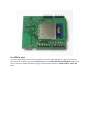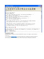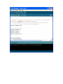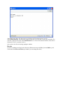
1
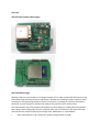
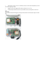
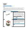
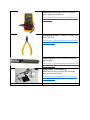
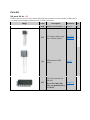
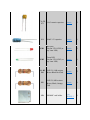
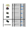
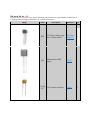
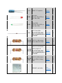
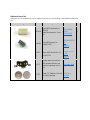
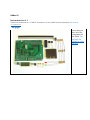
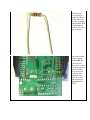
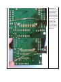
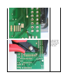
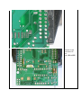
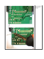
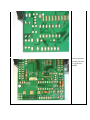
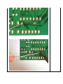
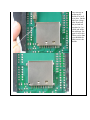
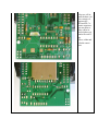
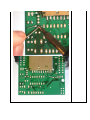
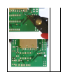
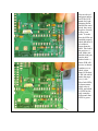
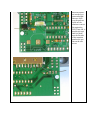
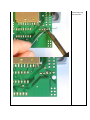
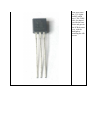
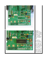
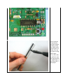
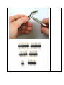
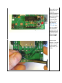
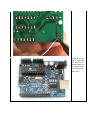
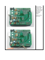
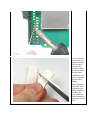
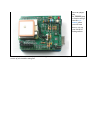
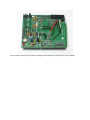
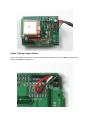
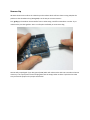
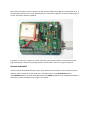
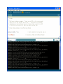
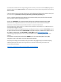
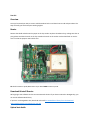
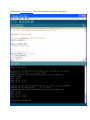
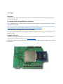
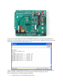
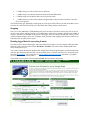
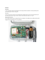
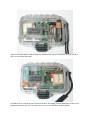
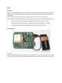
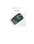
www.robotshop.com Adafruit GPS Shield User Manual RB-Ada-05 GPS ShieldDIY location & data-logging......................................................................2 Make it..........................................................................................................................4 Preparation.....................................................................................................................5 Parts list.........................................................................................................................7 Solder it.........................................................................................................................14 Use it..............................................................................................................................46 Modules………………………………………………………….................................46 Wiring............................................................................................................................48 Connect.........................................................................................................................50 Test GPS........................................................................................................................57 GPS Logging.................................................................................................................60 Enclosure.......................................................................................................................69 Power.............................................................................................................................71 Resources......................................................................................................................73 Downloads……………………………………………………………………………..74 Overview GPS Shield DIY location & data-logging GPS shield & data-logger Would you like to use your Arduino to create geo-locative art? Or make a custom GPS device that can log sensor data along with the precise time and location? Perhaps you're looking to make a tracker, or want to make your own geocaching hardware. You are in luck! Here is my design for a Arduino shield that is perfect for any sort of project or artpiece that requires GPS precision time or location data. This shield supports any of four popular GPS modules and stores data on a standard DOS-formatted SD flash memory card. Simply plug it into your computer when you've finished your data capture and the plain text files are ready for importing into Google Earth, GPSvisualizer, or a spreadsheet. Power consumption: 5V @ ~70mA (less if power-saving methods are used) Approximate run times: 3 hours on a 9V battery and up to 12 hours with a MintyBoost (I'm still in the process of getting real data) Weight of shield, card, suggested GPS module, and Arduino: 2.6 oz / 75g Included example sketches show how to parse NMEA sentences, and log data to a text file on card More ideas... You can build a waterproof GPS logger by putting the shield, Arduino and small power supply in an Otter Box! Make it Lets go! This is a vey easy kit to make, just go through each of these steps to build the kit 1. Tools and preparation 2. Check the parts list 3. Assemble it Preparation Tutorials Learn how to solder with tons of tutorials! Don't forget to learn how to use your multimeter too! Tools There are a few tools that are required for assembly. None of these tools are included. If you don't have them, now would be a good time to borrow or purchase them. They are very very handy whenever assembling/fixing/modifying electronic devices! I provide links to buy them, but of course, you should get them whereever is most convenient/inexpensive. Many of these parts are available in a place like Radio Shack or other (higher quality) DIY electronics stores. I recommend a "basic" electronics tool set for this kit, which I describe here. Soldering iron. One with temperature control and a stand is best. A conical or small 'screwdriver' tip is good, almost all irons come with one of these. A low quality (ahem, $10 model from radioshack) iron may cause more problems than its worth! Do not use a "ColdHeat" soldering iron, they are not suitable for delicate electronics work and can damage the kit (see here) Check out my recommended basic soldering iron and where to buy. Solder. Rosin core, 60/40. Good solder is a good thing. Bad solder leads to bridging and cold solder joints which can be tough to find. Dont buy a tiny amount, you'll run out when you least expect it. A half pound spool is a minimum. Check out my recommended basic solder and where to buy. Multimeter/Oscilloscope A meter is helpful to check voltages and continuity. Check out my recommended basic multimeter and where to buy. Flush/diagonal cutters. Essential for cutting leads close to the PCB. Check out my recommended basic diagonal cutters and where to buy. Desoldering tool. If you are prone to incorrectly soldering parts. Check out my recommended basic desoldering tool and where to buy. 'Handy Hands' with Magnifying Glass. Not absolutely necessary but will make things go much much faster. Check out my recommended basic 3rd hand tool and where to buy. Good light. More important than you think. Parts list Kit parts list for v1.1 Check to make sure your kit comes with the following parts.Sometimes we make mistakes so double check everything and email [email protected] if you need replacements! Image Name Description Datasheet Qty PCB Printed circuit board v1.1 Adafruit 1 IC1 3.3V linear voltage regu- MCP1700lator, 250mA current 3302E/TO 1 Q1 PNP transistor, EBC pinout PN2907 1 3.3v level converter for SD card IC2 74AHC125 If you don't have this part, you probably have a v1.0 kit! 1 C1, C2, 0.1uF ceramic capacitor C3 Generic 3 100uF / 6V capacitor Generic 1 LED1 Red LED Lite-On LTL-1CHE (or any 3mm LED) Generic 1 LED2 Green LED Lite-On LTL-1CHG (or any 3mm LED) Generic 1 R1, R2, 1/4W 5% 1.0K resistor R4 Brown Black Red Gold Generic 3 Generic 1 Tyco 2041021-3 1 C4 1/4W 5% 10K resistor R3 Brown, Black, Orange, Gold SD SD/MMC card holder EM406A 6 pin SMT connector for EM-406A Either Horizontal or Vertical JST BM06BSRSSTB(LF)(SN) 1 B3F-1000 1 Generic 1 8 pin female header (1x8) Generic 1 RESET 6mm tactile switch ICSP 6-pin ICSP header TXJMP Jumper/shunt 36 pin male header (1x36) Generic 1 Generic 1 Kit parts list for v1.0 Check to make sure your kit comes with the following parts.Sometimes we make mistakes so double check everything and email [email protected] if you need replacements! Image Name Description Datasheet PCB Printed circuit board IC1 3.3V linear voltage regu- MCP1700lator, 250mA current 3302E/TO Q1 PNP transistor, EBC pinout C1, C2, 0.1uF ceramic capacitor C3 Qty Adafruit PN2907 Generic 1 1 1 3 100uF / 6V capacitor Generic 1 LED1 Red LED Lite-On LTL-1CHE (or any 3mm LED) Generic 1 LED2 Green LED Lite-On LTL-1CHG (or any 3mm LED) Generic 1 C4 3.6V Zener diode D1 If you don't have this 1N5227B part, you probably have a v1.1 kit! R1, R2, 1/4W 5% 1.0K resistor R7, R11 Brown Black Red Gold Generic 1 4 1/4W 5% 4.7K resistor yellow purple red R3, R5, Generic R6, R8 If you don't have this part, you probably have a v1.1 kit! 1/4W 5% 10K resistor R4, R9, Brown, Black, Orange, R10 Gold SD/MMC card holder 4 Generic 3 Tyco 1734234-1 1 EM406A 6 pin SMT connector for EM-406A Either Horizontal or Vertical JST BM06BSRSSTB(LF)(SN) 1 B3F-1000 1 Generic 1 8 pin female header (1x8) Generic 1 RESET 6mm tactile switch ICSP 6-pin ICSP header TXJMP Jumper/shunt 36 pin male header (1x36) Generic 1 Generic 1 Optional parts list These parts are not included in the kit, but might be necessary if you're planning to attach different GPS modules. Image Name Description 8 pin SMT connector for EB-85A EB-85A Either Horizontal or Vertical 8 pin SMT header for Trimble Trimble GPS A1035- 20 pin SMT header for TyD co A1035-D Datasheet Qty JST BM08BSRSSTB(LF)(SN) 1 LPPB042NFSPRC Digikey FTSH-111-01L-DV Digikey BATT Backup battery holder for GPS modules that do not contain a supercap or battery BATT 12mm 3V Lithium coin cell CR1220 or for battery backup CR1216 Keystone 3000 1 1 Solder it! Instructions for v1.1 These are the instructions for v1.1 ONLY! If you have a v1.0 kit, DONT use these instructions! Check out the v1.0 instructions Go go go! Check that you have all of the components for the shield. The full parts list (BOM) is available here. Get ready by placing the PCB in a vise Heat up your soldering iron to 700deg F, clean the tip and make sure your sponge is wet If you are building the shield from a kit, you'll notice that the small 6-pin JST connector is presoldered. If you bought just a PCB or are making your own, use surface mount soldering techiques to solder the connector you are planning to use. Lets go! The first part we're going to solder is a 1K resistor. The 1.0K resistor is striped Brown Black Red Gold. Bend the resistor into a staple as shown. Place the resistor in the location marked R4. Resistors do not have polarity whi ch means you can put it in 'either way' and it will work just fine. Bend the wire legs out so that the resistor sits flat against the PCB. Turn the PCB over. Using your soldering iron tip, press and heat both the pad (the silver ring around the hole) and lead (wire) at the same time for 2 or 3 seconds. Then poke the end of the wire into create a nice solder joint. Do this for both leads. Using your diagonal cutters, cut off the long leads just above the solder joint. Repeat for the two other 1K sistors, R1 and R2 Flip over the PCB and solder the 2 resistors. Clip the two resistors' leads Next is the final resistor, this one is a 10K resistor R3 Once you are feeling comfortable with the resistors, lets do the SD card holder. The holder is surface mount (there are no wires that go through the board) but the spacing is very generous, so it wont be difficult. The holder has two bumps that 'snap' into place on the PCB. Make sure that the bumps are engaged and the holder is sitting flat. The first step to soldering the holder is to 'tack' it in place. On the sides are 4 large tabs. Heat both the pad and tab together for 3 seconds and solder the tab down. Repeat for all 4 tabs. When you're done you shouldn't be able to move the holder. Next, solder the 7 large leftmost pins of the holder to the corresponding pads. Use a sparing amount of solder so that you wont end up bridging two pins by accident. If you aren't skilled at SMT soldering, you can simply skip the three smaller pins, they're not at all necessary Next we will install the three yellow ceramic capacitors C1 C2 and C3. Ceramic capacitors are not polar so they can be inserted either way and will work fine. Place, solder and clip the capacitors. Next are the red and green indicator LEDs. LED stands for Light Emitting Diode, and like the zener diode, they must be place correctly or they wont work. To make sure the LEDs are installed properly, check that there is a lead that is longer than the other. This lead is the positive (+) lead. Make sure that this lead goes into the hole marked with a + on the PCB silkscreen, as shown. Another way to check is that many LEDs have a 'flat' side which marks the negative (-) side. Place both LEDs, it doesnt matter which color is LED1 and which is LED2 but the code examples will assume that LED2 is green. Solder and clip the two LEDs. Next we will solder in the PNP transistor. The transistor is in a TO-92 package, with a semicylindrical plastic part and three legs. There is another TO-92 part which is the voltage regulator. These two parts look very very similar but are completely different so its important to look carefully and make sure that you are going to solder in the part that says PN2907A Insert the transistor into the location marked Q1. Because of the way the pads are layed out, the transistor wont sit flat against the PCB. Thats OK, it should stick up a little bit. Make sure the flat side of the transistor matches the outline on the silkscreen Solder and clip the transistor Now we'll place the 3.3V regulator IC1 which says 1700-3302E on it. Its shaped just like the transistor and goes in the PCB the same way, with the hemisphere matching the silkscreen. The next chip IC2 is the 74AHC125 which is the 3.3V buffer chip that converts the 5V signals from the Arduino to the 3.3V SDcard IC's must be placed a certain way, or they dont work. Make sure you get this right because if the part is in wrong its a real pain to fix! On one end of the chip is a round notch. In this photo its on the right. Make sure this notch matches the silkscreen underneath where there a similar round notch. Solder in all the pins of the chip Next is the RESET butto n and electrolytic capacitor C4. Electrolytic capacitors are polarized and must be placed correctly. Like the LEDs, the longer lead of the capacitor is the positive (+) lead. Make sure this lead is placed in the hole marked with a +. The button is symmetric, snap it in place. Solder and clip Next, break the 36-pin header strip into smaller sections so that the shield can be placed on the Arduino. You can use pliers or diagonal cutters. You will be able to perfectly snap the long strip into 2 8-pin strips, 3 6pin strips and 1 2pin jumper. Place the 2x3 pin header into the location marked ICSP Ma ke sure the long part of the header is sticking up. If you are planning to connect the shield to an FTDI USBTTL cable (see the user manual for more information) then you should place one 6 pin strip in the header location marked FTDI. Solder in the headers. You may want to use tape to keep them in place while you solder. Place the 2 6-pin and 2 8-pin headers into your Arduino (make sure its not powered up when you do this, OK?) Slip the shield onto the Arduino as shown. The tips of the headers should all match up and poke through the shield. Solder all of the header pins. Place the 2-pin strip in the location marked TXJMP ( its near the top). Make sure the long part of the header is sticking up. Finally, you will probably want to install the 8-pin female header into the digital breakout location as shown. This will let you do a bunch of hacking around while you're figuring out how you want to set up your GPS logger Solder them in place You can cut the foam sticky into quarters and peel off one side so that the GPS module will not sit directly on the shield (which could short a connection and damage the whole thing!) Dont remove the other side of the tape and permanently attach the module until you've done all the tests and configuration! (just in case) Place the jumper into the TXJMP jump er location and go onto the user manual where you will learn how to wire up your shield for testing and use. Place the jumper into the TXJMP jumper location and go onto the user manual where you will learn how to wire up your shield for testing and Use it! Once you have built the shield, it is time to get your module, test and configure it 1. Picking a module 2. Wire it up 3. Connecting directly to computer 4. First Arduino + GPS test 5. GPS logging 6. Enclosures 7. Power & Batteries Modules Overview This shield requires a GPS module (sometimes called an "engine board" or "engine module") to receive the timecode data from GPS satelites. There are dozens of GPS modules on the market, each with slightly different specifications. The Adafruit GPS shield v1.0 supports 4 popular hobbyist modules and is geared specifically for the EM406A: the required connector is already soldered on and ready to go. If you want to use a different module, check the parts list for the required connector as they are not included. Supported modules Image Name Description Sirf III chipset module USGlobwith analSat tenna, EM-406A supercap, lock indicator ETek EB85A FV-M8 Docs Distributors Power I/O Notes ~3.3 V Sirf TTL Adafruit ($6 5binary seri0) 6.5V protocol al 4800 Softwar baud e No backup battery required User Guide User Guide Ohararp ($5 3.3Datashe 5) DPCAV ($8 5V et 5) Comma nd ~3.3 V TTL 5 Hz seri- upal date! 3840 0 referenc e baud Softwar e Flyer Tyco A1035-D Trimble Lassen iQ Sirf III chipset module with antenna User Guide 3.3V TTL Mouser ($62 seriSirf 3.3V ) al binary 4800 protocol baud Softwar e 3.3V Sparkfun ($ TTL 57) seri3.3V +Antenna ($ al 19) 4800 baud Requires battery & antenna Wiring Overview Even after soldering all the parts, there is some 'fly wiring' that is required to get the shield to do what you want. The reason it was designed that way is so that people with unique requirements could easily customize how they want the shield. However, we will cover the most common cases. Connections There are two parts of the shield: the GPS module interface and the SD card interface. The SD card must be connected to the Arduino digital pins 13, 12, 11, and 10for it to work and so those pins are 'taken'. The GPS module interface does not have to be connected to any -particular- pin so they are left free for you to jumper with common wire.. The GPS module interface is as follows: TX - this is the transmit pin, data that comes from the GPS module with location data RX - this is the receive pin, data that goes to the GPS module to configure it PWR - this pin is connected to a transistor that controls power to the GPS. When this pin is set to LOW the GPS module turns on and when the pin is set toHIGH the GPS turns off. L1 and L2 - these are the two red/green LEDs on the shield which can be used for indicating whether data is being logged, if there is a GPS location lock, etc. PPS - this is the GPS syncronized pulse clock, it pulses exactly once a second. CD - this is actually part of the SD card interface, its a card detect switch and is connected to ground when a card is in the holder. Its not really necessary but is included in case you'd like to use it WP - this is also part of the SD card interface, its a write protect switch and is connected to ground when the little latch on the side of the SD card is set to 'lock'. Its not really necessary but is included in case you'd like to use it The only really important pins are PWR, TX and RX. Some modules work even when RX is not connected to anything (floating) but many act kind of strange so I suggest always connecting it up. Make your wires Cut three pieces of wire, two about 1" long and one 2" long. Solder the two shorter ones to RX and TX. Solder the longer one to PWR. Now continue to the next step, which is testing the GPS module by connecting it to your computer Connect Overview The first thing we will do is test the GPS by connecting it directly to the computer. This is useful because sometimes you may want to get geolocative data directly into software. You dont need to do this step, but it can be helpful to determine if your GPS module is working - one less thing to worry about later. You can connect with an FTDI cable or use your Arduino Option 1. Wiring using an FTDI cable The easiest way to connect the GPS module to a computer is to remove it from the Arduino and connect the GPSPWR line to ground. Then plug in an FTDI cable and connect using a serial terminal program (or the Arduino IDE, see below) Option 2. Wiring using an Arduino Remove the shield from the Arduino. Connect the GPS TX line to digital pin 1 and the RX line to digital pin 0. Connect the PWR line to digital pin 2. Remove chip We want the GPS unit to talk to the FT232 chip on the arduino which will let us listen in using USB, but the problem is that the Arduino chip (ATmega168) is in the way so we must remove it. First, gently pry the Arduino microcontroller from its socket using a small flat screwdriver or similar. Try to make sure the pins dont get bent. Put it in a safe place. Preferably in an anti-static bag. Next we will jumper digital i/o pin 2 to ground (LOW) which will make sure the GPS unit is turned on when we connect up. Use a spare piece of wire and plug them into the empty socket as shown. Triple check to make sure you have the jumper in the proper socket holes! Plug in & power up Plug the shield into the Arduino, and plug the GPS module into the little connector Now connect the Arduino to your computer via USB. The GPS module should light up, indicating that its on. If the GPS module doesnt turn on, check the PWR jumper is connected to digital pin 2, that the socket jumper is correct, and that the Arduino is powered. If possible, try to be near a window or outside. If possible, place the GPS module so that the antenna (the large silver square) is outside and pointing upwards. This will make it easier for it to get a location fix. Connect and watch! Lastly we will use the Arduino software to open up the USB serial port and listen in on the GPS. Start up the software, make sure that the correct Serial Port is selected and click on the Serial Monitor button. Select 4800 baud (unless you have an EB-86A which may be 38400 by default) If you changed the baudrate in some way, try all the possibilities until you get a clear output You should see a whole bunch of strange looking numbers and data, all the lines start with $GP (Geographical Position). These lines are NMEA sentences which indicates that the GPS is functioning properly and is sending data as it should. If you are outside or have a clear view of the sky, you may be able to get fix data! In the sentences above, look for the line that says$GPGRMC,211420.565,A,4042.3932,N,07400.4680,W,,260608,,*19 This line is called the RMC (Recommended Minimum) sentence and has pretty much all of the most useful data. Each chunk of data is seperated by a comma. The first part 211420.565 is the current time GMT. The first two numbers 21 indicate the hour (2100h, otherwise known as 9pm) the next two are the minute, the next two are the seconds and finally the millseconds. So the time when this screenshot was taken is 9:14 pm and 20 seconds The second part is the 'status code', if it is a V that means the data is Void (invalid). If it is an A that means its Active (the GPS could get a lock/fix) The next 4 pieces of data are the geolocation data. According to the GPS, my location is 4042.3932N (Latitude 40 degrees, 42.3932 minutes North) &07400.4680W. (Longitude 74 degrees, 0.4680 minutes West) To look at this location in Google maps, type +40° 42.3932', -74° 00.4680' into the google maps search box. Unfortunately gmaps requires you to use +/- instead of NSWE notaion. N and E are postive, S and W are negative. The next data is not used, the one after that is 260608 which is the current date (26th of June, 2008). Finally there is the *xx data which is used as a data transfer checksum Once you get a fix using your GPS module, verify your location with google maps (or some other mapping software). Remember that GPS is often only accurate to 5-10 meters and worse if you're indoors or surrounded by tall buildings. Now may be a good time to read up all about NMEA and how GPS works. Test GPS Overview Once you've tested your GPS, its time to add the Arduino back in and show how to read and parse data. This step will verify you have both parts working togther. Rewire Remove the shield and take out the jumper in the chip socket. Re-place the Arduino chip, making sure that no pins get bent and that the notch in the chip matches the notch in the socket. Put the shield back on and rewire it so that the jumpers now look like this: TX should connect to pin 2, RX connects to pin 3 and PWR connects to pin 4. Download & install libraries We're going to use software serial to communcate with the GPS. If you have an NG with a ATmega8 chip, you can use the SoftwareSerial library. If you have an ATmega168 or 328, download and install the NewSoftSerial library from the download page. Install the library as necessary for your IDE Upload test sketch Download the GPStest_RMC sketch from the download page and upload it to the Arduino. This time, when the GPS module gets a fix, it will parse out the data and display it in slightly more useful format. If you're planning to make locative projects that don't log to the SD card you can stop now. This sketch can provide the backbone of most locative art projects! GPS Logging Overview OK finally we get to the part thats interesting, where you can log GPS data (and possibly other sensor data as well) to a memory card. For people with Atmega168 based Arduinos We've updated our code to make it easier for people with modern arduinos (Atmega328 and higher) to use the shield with the latest IDE. However, this means we need to remove support for '168 based Arduinos. If you have a '168 Arduino please see our older page for using the unsupported library that works on '168 arduinos You will need a Atmega328 or better Arduino! Just what it says, this tutorial now only supports using the Atmega328. Its been a few years so upgrade if you still have a '168! Format a SD card You'll need a SD card formatted in FAT16 or FAT32, most SD cards are formatted correctly 'out of the box'. You can see the formatting tutorial over at the Wave Shield page Unplug the Arduino, remove the GPS module (for now) and insert the SD card into the holder on the underside of the shield. For MEGA users If you are using a Mega (1280 or 2560) you will have to tweak the SD card library to allow to use the same pins as the Uno. To do this, open up the Sd2Card.h file in the ArduinoIDE/libraries/SD/utility folder (you'll have to explore the Arduino IDE directory/App to find it) and then change the #define MEGA_SOFT_SPI 0 to1 Download & Install We will be using the SD library, in the latest Arduino IDE. If you have v21 or higher, it will be built in already! (nice!) Next download the GPSLogger sketch. If your GPS module talks at something other than 4800, change the sketch with the new baud rate. Upload it to the Arduino and open up the Serial Monitor at 9600 baud. You should see the above. The logger starts up, initializes the SD card and creates a new file called GPSLOG00.TXT. That file will be empty because there is no GPS data, so dont worry about that. The next time it starts the file will be called GPSLOG01.TXT, etc. If the SD card doesnt initialize, check that it is formatted FAT16/32, try another card, etc. Once you have the SD card working, unplug the Arduino. Re-wire We need to updating the wiring for the LEDs. Keep TX connected to pin 2, RX to pin 3 and PWR to pin 4. Then connect the LED1 and LED2 to pin 5 and 6 ( you can change these later) Connect up the Arduino again and watch the Serial Monitor. This time you will see notification that GPS strings were received and properly written to the card You will need to have a lock from the GPS to get proper location data so stick the Arduino+GPS outside for a bit. You'll see GPRMC and similar NMEA strings, Then we see a # right afterwards. This is feedback from the Arduino saying that a NMEA string was received, passed the checksum and properly written. Here are all the characters the logger will print as feedback: # - NMEA string received, checksummed and written * - NMEA string received, but there was no checksum ~ - NMEA string received with checksum, but the checksum didnt match ! - NMEA string received but the data was too big for our buffer _ - NMEA string received, but the Arduino is programmed to only save data when there is an active fix so it was ignored. The LEDs will also give indication to whats going on. If the green LED (LED1) is lit, that means that we have a location fix. If the red LED (LED2) is lit, that means data is being written to the SD card. Stopping Once you see the multitudes of LEDs blinking away for a bit and you feel like its time to stop, here is the safest way to turn off the Arduino. Just like you wouldnt want to turn off your computer while its in the middle of writing a document, you shouldnt cut the power to the logger while its writing to the SD card as there is a risk of data corruption. Simply remove the TX jumper when you want to stop logging. Wait till the red LED is not lit and then you can safely remove power. Reading logged data & converting formats Now that you have turned off the logger and removed the SD card, place it in your computer's SD card reader and open it with a text file reader (such as WordPador TextEdit). You will see those familiar NMEA sentences staring back at you! You can now import this data into programs like Google Earth. Some programs require special formatted data (which is quite annoying) and since this is such a problem, there is a website devoted just to solving this problem calle GPSvisualizer. Lets go thru how to convert NMEA data to Google Earth since thats very popular. (You can also convert to other formats.) The defaults are pretty good. I like uncompressed kml data but it doesnt really matter. Under Upload your GPS data here you should Browse... and select the GPSLOGxx.TXT you'd like to convert, Click Create KML File and then you can download the KML file directly into Google Earth for viewing Customizing the GPSLogger There's a few small things you can do to customize the GPS logger. You can turn on and off specific NMEA sentences. For example #define LOG_GSA 0 // satelite data indicates that we do not want the GPS to emit satelite data. This saves memory card space and reduces power consumption. To turn on $GPGSA data, simply set it to 1: #define LOG_GSA 1 // satelite data You can also set it to only log data when we have a location fix (0 means log eveything, 1 means only log during fix) #define LOG_RMC_FIXONLY 0 // log only when we get RMC's with fix? You can turn WAAS on or off. This is an addition to North America where GPS can use ground stations to get up to 3 meter radius precision. Set it to 0 to turn off. #define USE_WAAS 1 // useful in US, but slower fix You can also save a bunch of power by putting the Arduino (and even the GPS module) to sleep. This doesnt make much sense if you need to log data once a second, which is the default. But if, say, you dont mind only grabbing data once every 10 seconds or minute, it can reduce power consumption a lot! The SLEEPDELAY constant says how long the Arduino should sleep (do nothing, using no power) between reads. Setting this to 0 means it never goes to sleep. 10 means sleep for 10 seconds. You can use any # up to 255 seconds (4 1/4 minutes) If you have the LOG_RMC_FIXONLY variable set, it will not go to sleep until- there is a valid fix sentence. #define SLEEPDELAY 0 // how long to sleep before reading another NMEA sentence If you want to really reduce power consumption, you can ask the Arduino to turn off the GPS module while it sleeps. You pretty much have to useLOG_RMC_FIXONLY with this option because the first 5 seconds after the GPS turns on is 'warm start' and you'll get about 5 no-fix data points before a fix is acquired. Its an advanced power saving feature and may require some experimentation. #define TURNOFFGPS 1 // probably only want to do this if the sleep delay > 60 or so Writing to CSV format One other annoying thing about NMEA is that theres no real standard for embedding sensor information into the data. So I wrote another sketch that will log RMC sentences, split them up into nice comma-seperatedvalues (CSV) and also log analog inputs 0, 1 and 2 values. Theres pretty much no more space for doing funky sensor processing on the Arduino but with the raw data, you can easily manipulate it on a computer by opening it up in a spreadsheet or data analysis program. Enclosure Overview if you're planning to take your GPS logger on the road, you'll want to protect it. Thats especially true if you're planning on a hike or sailing trip. Soft cases An easy source of nice cases for your portable project is digital camera cases. You can get them at your local camera/electronics shop or online. Look for ones that measure about 4" x 3" by 1" Waterproof hard cases You can get waterproof (and crushproof) boxes from Otterbox. The 1000 series can hold an Arduino, GPS logging shield, and 9V battery with a clip perfectly. If you use a smaller battery holder and skip the USB connector part of a mintyboost, you can stuff all of that in a series 1000 case as well The 2000 series is a little larger and can hold an Arduino, GPS logging shield & Mintyboost as well as your toothbrush and some trail mix. The cases come in clear so you can easily see blinking LEDs. Power Overview If you have a GPS module hooked up to your Arduino, there's a good chance you're looking to run it on batteries or some other portable power supply. Here are some hints on what you can use and how to reduce power. You can read my article about batteries and how to pick the best one for your project here Current power test data: (Please post your own findings to the forums so they can be integrated here) 2 Energizer Alkaline AA w/ Mintyboost, logging 1Hz RMC fix data, no sleep - 12 hours 2 Energizer Alkaline AA w/ Mintyboost, logging 1Hz RMC fix data, 30s sleep - 16.5 hours 2 rechargeable AA w/Mintyboost, logging once a minute with sleep - 30 hours Power supplies 9V battery These are easy enough, pair it with a battery clip or holder with a 2.1mm barrel jack and you can simply run the entire system off of this. Most 9V provide about 400mA-hours of current (~5 hours of run time) Mintyboost A mintyboost will convert 2 AA's (3V) to USB (5V). You can build it 'as usual' and connect it up via a standard USB cable or wire it up directly as shown above so that it will fit into a smaller case. You can use rechargeables or Alkalines. Provides about 2000 mA-hours of current (~20 hrs of run time) Huge battery pack This pack will power the whole setup from the DC jack and last at least 10 longer than a 9V Reducing power requirements There's three things that use up power in the GPS logger: the Arduino, the GPS module and the SD card The Arduino chip is always using about 10mA of current, maybe a little more if there are LEDs. You can reduce this a lot by making it go to sleep The USB chip uses about 10mA as well. If you dont have a USB cable plugged in, this will save you a bit of power The GPS module uses between 20mA and 60mA of current, depending on whether it is trying to acquire a lock or whether it is merely tracking. You can reduce this by using the GPSPWR pin to turn the GPS off between reports. The SD card uses 20mA but only when writing data. You can reduce this by sleeping between reports and only logging fix data from the GPS which translates to less data written. The "log everything all the time" configuration draws about 75mA The "sleep for 10 seconds between reads but don't turn off the GPS" draws about 65mA If you are outside where the GPS can get a fix pretty quickly, you can use as little as 10mA on average by logging only once a minute and turning off the GPS between logs. Resources NMEA NMEA is the format that pretty much all GPS modules use to communicate. Understanding NMEA is essential to working with GPS! All about NMEA MTK Packet checksum generator Tutorials GPS FAQ Trimble's GPS tutorial Garmin's GPS tutorial Software If you want to connect the GPS directly to your computer, you can use special software that makes it easy to configure the modules SirfDemo v3.82 SirfDemo software tutorial (for Sirf chipset GPSes) SirfDemo User guide (for Sirf chipset GPSes) MiniGPS (for ETek EB-85) Other cool GPS things Here are some of the nice projects/products that inspired me to build this shield Arduino GPS module from Libellium OHARARP waterproof GPS logger Sparkfun GPS logger Downloads Current Code & Libraries NewSoftSerial library. - This code is run by Mikal Hart and you may also want to see if he has any new version. It's GPL GPS test parsing sketch - uses NewSoftSerial to communicate with the GPS module GPS basic logging sketch - uses NewSoftSerial to communicate with the GPS module and SD library to log data Click on the DOWNLOADS button in the top right corner to download from github All of this example Arduino code is Public Domain. Enjoy! For information how to use and install libraries, see our tutorial! Older code AF_SDLog library. If you have the Wave Shield library installed, you may have to uninstall it (remove it from the library folder) since it will conflict. This has been supplanted by the SD library built into the Arduino IDE. The only good thing about it is that it will (barely) fit and run into a '168 Arduino so if you happen to be stuck with a '168 and can't upgrade, this code may be handy. Otherwise, please use the newer code above GPS basic logging sketch - saves NMEA data v2 fixes bugs that prevented it from working with '328P arduinos GPS CSV logging sketch - saves RMC sentences in CSV format with data from 3 analog sensors. This code is based off of Roland Reigel's SD card code, and is also GPL Hardware All files are CC 2.5 Attrib., Share-Alike Schematic for v1.1 in EagleCAD format Layout for v1.1 in EagleCAD format Schematic for v1.1 in PNG format And older files (you likely dont want them but they're here for reference) Schematic for v1.0 in EagleCAD format Layout for v1.0 in EagleCAD format Schematic for v1.0 in PNG format