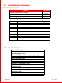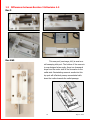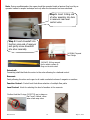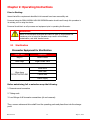
1
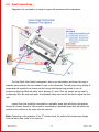
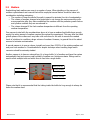
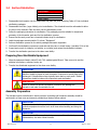
Small Animal Hollow Organ Bioreactor Operator’s Manual Regenerated Organs for Transplant 84 October Hill Drive S#11, Holliston, MA 01746-1371 USA www.HARTregen.com 774.233.7300tele [email protected] Revision 2.2x 1 July 15, 2015 Contents Contents 2 Overview 3 General Safety Requirements 4 Chapter 1 - Introduction 1.1 Equipment Components & General Overview 5 6 1.2 Required Supplies & Equipment 10 1.3 Differences between Rev 3 & Rev 4-5 11 Chapter 2 - Operating Instructions 2.1 Sterilization 13 2.2 Fluid Connections 14 2.3 Medium 15 2.4 Surface Disinfection 17 2.5 Post-Sterilization Assembly 18 2.6 Alternative Flow Path 19 2.7 Transporting the Chamber 19 2.8 Sealing Ports 19 2.9 Spare Parts 20 Chapter 3 - Care & Maintenance 3.1 Cross-Infection Prevention / Universal Precautions 23 3.2 Cleaning 23 3.3 Specifications 23 3.4 Troubleshooting 24 3.5 Frequently Asked Questions 25 Update Log Revision 2.2x 27 2 July 15, 2015 Harvard Apparatus Regenerative Technology (HART) partners with leading global scientists to provide specialized solutions. The company is uniquely positioned to develop advanced instrumentation to accelerate regenerative medicine, tissue engineering and cell therapy experimentation. From the beginning, we worked closely with leading global researchers to produce products with the highest levels of performance, quality and support necessary for the new challenges of your life science research. We look forward to working with you to develop new tools to assist you in solving the new challenges of regenerative medicine from the lab bench to the patient. There are thousands of publications, in regenerative medicine to stem cell research, utilizing HART products, but we are now introducing some newly developed products: one for regenerative organ generation and one for small volume cell delivery into organs. These products will serve the researcher and the physicians to accelerate the research and utilization of that research in patients. Disclaimer: Use of the Hollow Organ Small Animal Bioreactor should be conducted by a trained and manufacturer qualified representative. Harvard Apparatus Regenerative Technology (HART) does not warrant unauthorized use of this product; HART does not warrant that the operation of this product will be uninterrupted or error-free and makes no claim of warranty or condition. HART reserves the right to change the instructions for use and any related products at any time without any prior notice and is not liable for any damages arising out of any change and/or alteration of the contents or product. This product is for RESEARCH USE ONLY and NOT FOR HUMAN USE. Copyright © 2014, Harvard Apparatus Regenerative Technology. All rights reserved. Harvard Apparatus Regenerative Technology owns the intellectual property rights to the Hollow Organ Small Animal Bioreactor. This material may not be reproduced, displayed, modified, or distributed without the expressed prior written permission of the copyright holder. U.S., international, and foreign patent applications are pending. Revision 2.2x 3 July 15, 2015 Warning and Caution Statements The use of a WARNING statement in this User Manual alerts you to a potential safety hazard. Failure to observe a warning may result in a serious injury to the user. The use of a CAUTION statement in this User Manual alerts you to where special care is necessary for the safe and effective use of the product. Failure to observe a caution may result in minor injury to the user or damage to the product or other property. Intended Use The Hollow Organ Small Animal Bioreactor is a vessel used to support a hollow organ scaffold for the purpose of cell-seeding; it is intended for research use only NOT FOR HUMAN USE WARNING: Use of this device in non-research settings must be conducted under local Regulatory requirements; consult your local Regulatory Authority. The following conditions must be met prior to using the Bioreactor: General Safety Requirements WARNING: The Bioreactor should only be used by qualified personnel who have been trained by the manufacturer or other authorized representative. Unauthorized use of this device is not recommended. WARNING: To prevent contamination, aseptic procedures must be followed and personal protective equipment must be worn at all times when handling and using the Bioreactor. WARNING: Wherever blood products are used, Universal Precautions must be followed. WARNING: DO NOT SUPPLY EXPLOSIVE GASES TO THE BIOREACTOR Facility Requirements Assure that the facility is able to provide a clean, safe, and suitable area for aseptic cell processing. It is recommend that all manipulations of the unit once sterile are performed in a biological safety cabinet (laminar flow hood). WARNING: Failure to provide a means to conduct aseptic cell processing may result in harmful contamination. Revision 2.2x 4 July 15, 2015 Chapter 1: Introduction The Hollow Organ Small Animal Bioreactor is a rotating, double chamber bioreactor designed for cell seeding and culturing both surfaces of a tubular matrix and includes rotational movement of the scaffold around its longitudinal axis. A polymeric chamber houses the biological materials throughout the culture period. Cylindrical scaffold holders are constructed with working end of different diameters—to house matrices of diverse dimensions—and a central portion of smaller diameter to expose the luminal surface of the matrix for cell seeding and culturing. A co-axial conduit links the inner chamber to the external environment through the chamber wall. This provides access to seed and feed the luminal surface of the construct. Secondary elements moving with the scaffold holder induce continuous mixing of the culture medium to increase oxygenation and mass transport. Revision 2.2x 5 July 15, 2015 1.1 Equipment Components (A) Drive Motor Base Plate: Plate that aligns the reservoir with the drive motor. (B) Control Unit: Independent controller of rotational speed. The bioreactor may also be controlled using an ORCA Controller. (C) Motor Drive: Drive motor responsible for rotation of the Arbor and organ. Arbor Assembly - General Overview The size of the organ required will dictate the number and size of inserts required. The organ size can vary from a 1.0—2.5mm ID, 9.4mm OD and a length of 7.7-65mm. Spacers are placed on either end of the arbor assembly. A minimum of two spacers are used with each Arbor (one for each end) and the cannula are inserted into the spacers. A maximum of 8 of the 5mm spacers can be used. Spacers are available in 6mm, 12 and 19 mm. The cannula pieces are dictated depending on the inner diameter of the organ. Typical choices include: 0.7mm, 1.0mm, 1.5mm, 2.0mm, 2.5mm, 3.0 5.0 mm and 7.0mm Step #1: Prepare the Arbor assembly by selecting the correct number of spacers and the correct cannula and mounting them onto the Arbor Step #2: Attach the organ if it is to be decellularized by suturing it into place. Note: early revisions of the Arbor had two arms. These arbors can be used interchangeably with the single arm current version. The arm was eliminated to facilitate suturing in the hollow organs. Revision 2.2x 6 July 15, 2015 1.2 Medium Replenishing feed medium can occur in a number of ways. When deciding on the manner of medium replenishment and removal that will be employed several factors should be taken into consideration including minimizing: The number of times the sterile flow path is opened to minimize the risk of contamination The volume of medium changed at a single time to not change the environment the cells are exposed due after they have conditioned the medium with the particular growth factors and cytokine cocktails they are accustomed to. The volume changed if the fresh medium temperature is different from the operating medium temperature. One manner to deal with the considerations above is to have a medium feed bottle large enough supply the entire amount of medium required throughout the experiment. This may slow the initial growth phase of the culture as it may take a bit more time for the cells to secrete the needed levels of cytokines to condition a larger volume of medium. However, in general this is the safest manner to minimize contamination. A second manner is to pour a volume, typically not more than 25-50% of the existing medium out and pour fresh medium in. Considerations for aseptic technique when handling large mouth reservoirs should be seriously studied. Clear Nut {1031141} Cap {1031140} T Fitting {1032597} Green Nut {1031142} Red Nut {1031143} Another manner is to have an external bag (s) or large bottle (s) of medium and have the system automatically feed and remove small volumes of medium on a continuous basis. Fittings can be used to allow multiple inlet and outlet lines to feed into a single bottle. Please note that it is recommended that the tubing inside the bottle be long enough to always be below the medium level. Revision 2.2x 7 July 15, 2015 Seal Wash Inlet Sweeping EC reservoir Inlet IC Inlet Driveshaft Function Control Level Control Seal Wash Outlet IC Outlet EC Reservoir Outlet Reservoir Outlet Flow Path Selection Using the selector knob on the lower left side (marked “F”) select the position that indicates the flow path required: Position 1: See small dot lower left side of “F” (looking at unit as shown) the outlet Lumen flow blocked; recirculates the medium / reagent back into the reservoir through the organ. Position 2: See medium dot high left side of “F” (looking at unit as shown) Lumen flow to lumen flow outlet (middle connector on bottom left) Position 3: See large dot high right side of “F” (looking at unit as shown) Lumen flow is recirculated into the reservoir Level Control: Small dot is on lower right side of “L” and represents the lowest level. Turn the know counter clockwise to the large dot on the left side which is the highest level of medium in the EC. DO NOT PLACE “L” in between the dots (left side of small dot and right side of large dot as this could close the exit of the fluid entirely. Revision 2.2x 8 July 15, 2015 1.2 Required Supplies & Equipment Bioreactor Components Equipment Part Number Complete Hollow Organ Bioreactor 1030300 Control & Motor Unit 1031206 Part Number 1030300 Description Complete Hollow Organ Bioreactor 1030170 Motor Unit 1030280 Control Unit 1030191 Organ Holder (Arbor) 1031247 Organ Connector (for multiple organs) 1031186 Organ Holder - Small Flat Tissue Spacers Cannulae Non-Bioreactor Components Sterilizing Strips Sterilizing Bags (250mm) Sterilizing Bags (350mm) Ethanol 70% (1L) Surgical suture thread with needle (size 4/0 or 3/0) Sterile serological pipette Sterile drape Sterile bottle (1L) PBS buffer, clinical grade (750ml) Culture medium (280ml) Inoculum (40ml) Male Luer integral lock ring plug (sterile) Laminar Flow Hood Adjustable Pipette CO2 Incubator Repipette Revision 2.2x 9 July 15, 2015 1.3 Differences between Revision 3 & Revision 4-5 Rev 3 Rev 4&5 This new port (see image, left) is used as a cell sweeping inlet port. The bottom of the reservoir is now designed at an angle; there is a downward slope from the motor side of the bioreactor to the outlet side. Recirculating reservoir media into this top port will effectively sweep accumulated cells down the incline towards the outlet passage. Revision 2.2x 10 July 15, 2015 The arbor is now labeled with the numbers 1, 2, 3, & 4 for easy recognition of the speed of rotation. The ports are now all standardized so that each are the same size; they are interchangeable. On the Rev 3, some of the ports had a smaller diameter. Rev 3 Rev 5 Swabble ports are available for ports not being used. An adapter {1031247} is available to allow multiple organs to be connected on a single arbor. Revision 2.2x 11 July 15, 2015 Note: During recellularization the organ should be mounted inside a laminar flow hood by an operator trained in aseptic technique and only after the bioreactor has been sterilized. Step 1: Insert O-Ring end of arbor assembly into hole in reservoir near level control valve Step 2: Insert driveshaft into function valve end of reservoir and gently screw driveshaft into arbor assembly {1032584} Tapered Luer Fittings {1032467} O-Ring removal tool is used to replace ORings on the drive shaft Driveshaft: Connecting shaft that links the motor to the arbor allowing for rotational control Reservoir: Cavity allowing the arbor and organ to sit inside a selected volume of reagents or medium Function Control: Control knob that allows selection of multiple flow paths Level Control: Knob for selecting the level of medium in the reservoir Confirm that the O-rings {1032774} are in place on the F and L Valves, otherwise a leak may occur Revision 2.2x 12 July 15, 2015 Chapter 2: Operating Instructions Prior to Starting: Assure that all the requirements identified in this manual have been successfully met. Personnel using the SMALL ANIMAL HOLLOW ORGAN Bioreactor should read through this procedure in its entirety prior to using the device. Personnel should train on all processes and equipment prior to operating the Bioreactor. WARNING: Failure to follow aseptic techniques and failure to train on all processes and procedures prior to using the bioreactor may result in critical delays, contamination, and other harmful events 2.1 Sterilization Bioreactor Equipment for Sterilization Sterile Pouch Equipment Bag #1 Culture vessel Other bags Organ Holder Parts Drive Motor Wipe down DO NOT AUTOCLAVE Base Plate Control Unit Power Supply Before autoclaving, foil or autoclave wrap the following: 1. Reservoirs and connectors 2. Tubing ends 3. Luer fittings of all bioreactor connections (do not unscrew). Then, remove valves and drive shaft from the operating ports and place them into the storage ports. Revision 2.2x 13 July 15, 2015 Pullout function valve and store here during autoclave operation Pullout level valve and store here during autoclave operation Pullout drive shaft and store here during autoclave operation The bioreactor was developed in order to allow for multiple sterilizations via standard laboratory procedures, including autoclavation, ethylene oxide sterilization and plasma sterilization. During sterilization processes, sealing surfaces such as Teflon stainless steel or Teflon o-ring should be disassembled to prevent permanent distortion. Sterilization steps: 1. Remove function valve “F” and store in the upper left storage port 2. Remove function valve “L” and store in the upper right storage port 3. Remove Drive Shaft and store in center right storage port 4. Remove arbor assembly from chamber 5. Place the bioreactor into the appropriate sterilization bag or container. After sterilization, place the unit into a laminar flow hood for final assembly to minimize contamination. Before autoclaving, foil or autoclave wrap the following: 1. Reservoirs and connectors 2. Tubing ends 3. Luer fittings of all bioreactor connections (do not unscrew). Then, remove valves and drive shaft from the operating ports and place them into the storage ports. Revision 2.2x 14 July 15, 2015 2.2 Fluid Connections Suggestion for recirculation of media to organ with maximum cell concentration. The Seal Wash Inlet–Outlet is designed to take a non-salt solution and flush it through a separate space between the two outside O-rings on the driveshaft. This will prevent any buildup of evaporated salt crystals from forming on the turning shaft during long periods of use. An intravenous drip bag filled with water set to between 0.1 and 0.5mL per minute can be used to continuously flush the seal wash path. An adjustable clamp can use don the line to adjust the flow rate. Lumen Flow Inlet should be connected to a peristaltic pump that will deliver the medium through the lumen. Reservoir Inlet should be connected to a peristaltic pump that will deliver the medium to the exterior of the organ into the reservoir. Note: Depending on the selection of the ”F” selector knob, the outlet of the lumen may change from the lumen flow outlet to the reservoir. Revision 2.2x 15 July 15, 2015 2.3 Medium Replenishing feed medium can occur in a number of ways. When deciding on the manner of medium replenishment and removal that will be employed several factors should be taken into consideration including minimizing: The number of times the sterile flow path is opened to minimize the risk of contamination The volume of medium changed at a single time to not change the environment the cells are exposed due after they have conditioned the medium with the particular growth factors and cytokine cocktails they are accustomed to. The volume changed if the fresh medium temperature is different from the operating medium temperature. One manner to deal with the considerations above is to have a medium feed bottle large enough supply the entire amount of medium required throughout the experiment. This may slow the initial growth phase of the culture as it may take a bit more time for the cells to secrete the needed levels of cytokines to condition a larger volume of medium. However, in general this is the safest manner to minimize contamination. A second manner is to pour a volume, typically not more than 25-50% of the existing medium out and pour fresh medium in. Considerations for aseptic technique when handling large mouth reservoirs should be seriously studied. Another manner is to have an external bag (s) or large bottle (s) of medium and have the system automatically feed and remove small volumes of medium on a continuous basis. Fittings can be used to allow multiple inlet and outlet lines to feed into a single bottle. Clear Nut {1031141} Cap {1031140} T Fitting {1032597} Green Nut {1031142} Red Nut {1031143} Please note that it is recommended that the tubing inside the bottle be long enough to always be below the medium level. Revision 2.2x 16 July 15, 2015 2.4 Surface Disinfection Equipment Drive Motor & Base Plate Control unit Power Supply 1. Disassemble the bioreactor into its components and place the parts according Table #02 into individual sterilization packages. 2. Disassemble the Arbor (organ holder) prior to sterilization. The driveshaft must be unthreaded to allow the arbor to be removed. Place the arbor into the sterilization pouch. 3. Follow the packaging instruction for sterilization. The packaging must be suitable for weight and geometry of the bioreactor parts and for the sterilization process. 4. Ensure that the each pouch has a chemical indicator strip for sterilization. 5. Label the packages according table 02, column “Equipment” 6. Perform sterilization process on the sterile packaged bioreactor equipment. 7. Confirm all the sterilization pouches are returned and there are no visual issues. (use table 02 for a list). 8. Inspect each pouch for integrity (no bubbles, no wrinkles) and review the sterilization indicator. 9. Transfer the sterilization pouches to the clean room facility. Preparing Non-Sterilizable Equipment 1. Wipe the equipment listed in table 03 with 70% medical grade Ethanol. Take care not to wet the electrical connections, switches, knobs, etc. 2. Transfer the disinfected equipment to the clean room facility. CAUTION: In the case where several bioreactors are being used simultaneously, a unique identifier should be placed on each bioreactor component to avoid parts being exchanged. Colored stickers have typically been used on each pouch. Similar precautions should be taken with components post sterilization. WARNING: Failure to follow the defined sterilization procedure may damage the bioreactor and make it unsuitable for use Assembly Preparation The bioreactor parts are delivered in sterile pouches. Unpacking and bioreactor assembly should be performed in a clean room environment provided by a laminar airflow cabinet. CAUTION: To prevent contamination, aseptic procedures must be followed and personal protective equipment must be worn at all times when handling and using the Bioreactor. CAUTION: Failure to strictly follow aseptic techniques may result in critical delays, contamination, and other harmful events. Revision 2.2x 17 July 15, 2015 2.5 Post-Sterilization Assembly NOTE: Two operators are recommended for unpacking and assembly. Sterile Bioreactor Equipment Other Materials Surgical suture thread with needle Bioreactor Sterile serological pipette Arbor & organ sterilized in sterile pouch Sterile bottle (1000 ml) Drive shaft PBS buffer Reservoir Cover Culture medium Transport Cover Inoculum Disinfected Bioreactor Equipment Drive unit Control unit Power Supply After sterilization, prepare the arbor assembly and organ in a laminar flow cabinet and then install the arbor into the Bioreactor reservoir. Cover the working surface for bioreactor assembly with a sterile cloth. Assembly steps: 1. Insert the O-Ring end of the Arbor assembly into the hole in the reservoir near the level control valve. Lower the free end of the Arbor into the reservoir cavity. 2. Insert the drive shaft into the function valve end of the reservoir and gently screw the drive shaft into the arbor assembly. Place you finger lightly on the top of the wide end of the arbor to prevent it from turning. 3. Place the cover on the Bioreactor. The cover is a loose fit allowing gas permeability while in an incubator. 4. Final assembly is recommended to be carried out in a laminar flow hood to minimize contamination. Normal aseptic technique is recommended in wiping down the flow path that has been sterilized when bringing it into the hood. Note: If the Bioreactor was sterilized in one location and must be transported to another, the use of a transport box is recommended. If the organ is to be transported from another building, it is recommend that the transport box with the Bioreactor inside be placed in a thermal maintenance container to minimize heat loss. Revision 2.2x 18 July 15, 2015 2.6 Alternative Flow Path An alternative to the reservoir may be used when initially seeding the organ. In this case the volume desired may be much lower than the flow path volume when using a reservoir. A 3 way stopcock {1032536} or Y fitting may be used on the inlet and outlet of either the EL or IL fluid path. This allows selection of alternate fluid paths. The first is through a standard reservoir. The alternate is through a tube connected between the two stopcocks minimizing the circuit volume. This may also be set up using a Y fitting before the inlet and after the outlet and placing a clamp on the tubing that the flow is to be restricted from. The 3-way stopcock is more elegant, however most stop cocks cannot be autoclaved. Thus they must be sterilized by ETO or chemically and then aseptically added to the flow path. The Y-fittings may be placed in the fluid path prior to autoclaving and the clamp added afterwards without cutting into the sterile fluid path. 2.7 Transporting the Chamber The use of a sealing cover {1031774} is recommended whenever transporting a chamber with a seeded organ. The culture chamber is designed to allow gas to be exchanged from the environment in an incubator. This will not prevent external air from entering the chamber if the unit is taken outside the incubator. The Sealing cover is made of Silicone Rubber and can be sterilized in a standard autoclave or by ETO gas or mild chemical sterilization. 2.8 Sealing Ports Swabble Ports {1031081} are available in bulk. These ports can be autoclaved once. They allow a sterile barrier to be maintained that can be connected to. Sterile Caps {1032581} are available. These are shipped in individual sterile blisters. Each cap has both a male and female dead end port. Revision 2.2x 19 July 15, 2015 2.9 Parts List Part Name Qty Part # Chamber Only 1030190 Controller Assembly 1030280 Drive Motor Assembly 1031206 Silicone Rubber Autoclavable Sealing Lid 1031774 Reservoir Culture Cover 1030199 Arbor (with O-Ring) 1030192 Organ Connector 1031247 Organ Holder - Small Flat Tissue 1031186 Arbor Spacer 6.3 mm (2 ea) 1031056 Arbor Spacer 12.7 mm (2 ea) 1031057 Arbor Spacer 19 mm (2 ea) 1031058 0.7 mm OD x 0.50 -> 2 mm ID Cannula Straight (2 ea) 1031050 1.0 mm OD x 0.38 -> 2 mm ID Cannula ball (2 ea) 1031051 1.5 mm OD x 0.82 -> 2 mm ID Cannula straight (2 ea) 1031052 2.0 mm OD x 1.02 -> 2 mm ID Cannula ball (2 ea) 1031053 2.5 mm OD x 1.90 -> 2 mm ID Cannula straight (2 ea) 1031054 3.0 mm OD x 2.03 -> 2 mm ID Cannula ball (2 ea) 1031055 5.0 mm OD x 4 -> 2 mm ID Cannula Ball (2 ea) 1031060 5.0 mm OD x 4 -> 2 mm ID Cannula straight (2 ea) 1031060 7.0 mm OD x 6 -> 2 mm ID Cannula straight (2 ea) 1032470 9.0 mm OD x 8 -> 2 mm ID Cannula straight (2 ea) 1032773 Drive shaft Assembly 1030203 Function Control Valve Knob 1030209 Level Control Valve Knob 1030208 O-Ring (Drive Shaft and Arbor) (10 ea) 1031205 O-Ring (F and L Valve) (10 ea) 1032774 1 1032467 (10 ea) 1032536 Tool, O-Ring insertion Stopcock Screw Flat Head (level cap) 1030288 Screw 10-24 x 3/8 Revision 2.2x (10 ea) 20 1030283 July 15, 2015 2.9 Parts List Part Name Qty Part # Function Control Valve Knob 1 1030209 Level Control Valve Knob 1 1030208 1/16” 25 1032297 1/8 “ 25 1032298 3/16” 25 1032299 1/4” 25 1032293 1/16” 25 1032294 1/8 “ 25 1032295 3/16” 25 1032996 1/4” 25 1032300 1/16” 10 1032075 1/8 “ 10 1032077 3/16” 10 1031124 1/4 “ 10 1031125 1/16” 10 1032076 1/8 ” 10 1032078 3/16” 10 1032079 1/4 ” 10 1032082 1/8 “ 25 1031087 ¼” 25 1031088 3/8” 25 1031089 ½” 25 1031091 Fitting Luer Female - Barb Fitting Luer Male – Barb Y Fitting Barb T Fitting Barb Clamp Revision 2.2x 21 July 15, 2015 2.9 Parts List (cont) Part Name Qty Swabble Port Part # (25 ea) 1031081 (25 ea) 1032581 (5 ea) 1032584 25 1031140 25 1031142 25 1033143 25 1031141 Sterile Sealing Caps Tapered Luer Fittings Nut Clear Cap Green Nut Red Nut Clear Nut 25 1032597 2L 1 1031100 1L 1 1031104 500 mL 1 1031105 T Fitting Luer – Slip - Slip Reservoirs Revision 2.2x 22 July 15, 2015 Chapter 3: Care & Maintenance Cross-Infection Prevention, Biohazardous Waste, and Product Disposal 3.1 Cross-Infection Prevention / Universal Precautions All blood products or products potentially contaminated by blood or other body/animal fluids should be treated as potentially infectious materials. Personal protective equipment should be worn at all times when using the Hollow Organ Small Animal Bioreactor to protect personnel from becoming contaminated as well as to help prevent cross-infection and cross-contamination. Bench tops, equipment, and other potentially contaminated surfaces should be cleaned and disinfected according to the manufacturers’ and/or the facility’s procedures. Any article used to clean potentially contaminated surfaces should be disposed of as Biohazardous Waste. CAUTION: Failure to use the manufacturers’ cleaning and disinfecting procedure could result in damage to the surface or equipment. Biohazardous Waste Dispose of biohazardous waste according to local Regulatory requirements. 3.2 Cleaning Flush all fluid paths with deionized water and either follow with or wipe with 70% IPA. These materials of construction will withstand virtually all biological reagents and cold sterilization agents. Stainless steel parts may be sonicated. 3.3 Specifications Size of Organ 1.0—2.5 mm ID, up to 65 mm in length is standard Rotation Speed 0 - 5 rpm Diagnostics Materials Power input output Positional Monitoring Autoclavable Teflon, PEEK and Stainless Steel 100-240 VAC, 50/60 Hz 1.7A 20V DC 3.25 A Revision 2.2x 23 July 15, 2015 3.4 Troubleshooting Arbor not turning: Check to see if the reservoir is in place and the drive shaft is connected to the motor. The retaining clamp is tightened during installation to maintain the connection. Check to see if the medium—blood being used has fouled the arbor. This can occur in high fibrinogen solutions. Excess Medium / Reagent build up in the reservoir: Check for clogging or fouling of the reservoir outlet line or port especially during a decellularization procedure. Medium level in the IC or EC flow path has gone dry: Confirm that there is sufficient medium in the inlet reservoirs and that the inlet tubing inside the reservoirs is below the medium level. Leaks: DO NOT USE BLEACH WHEN CLEANING THE BIOREACTOR AS IT HAS BEEN SHOWN TO CAUSE FAILURE OF COMPONENTS DURING AUTOCLAVE OPERATIONS. Also, be sure to check O-Rings and replace as necessary. Revision 2.2x 24 July 15, 2015 3.5 Frequently Asked Questions Is the retainer clamp missing from my unit? The retainer clamp design did not fit as well as it was supposed to, and since it did not seem to be necessary, we have not been shipping it with the product. A new clamp is in the process of being developed to make sure the drive mechanism does not slip and disengage itself. How does the "seal wash inlet" and outlet work? This passage is designed to take a non-salt solution and flush it through a separate space between the two outside o-rings on the driveshaft. This will prevent any buildup of evaporated salt crystals from forming on the turning shaft during long periods of use. As an example, an intravenous drip bag with water set to between 0.1mL and 0.5mL per minute to continuously flush the seal wash path could be used. Should I sterilize using plasma sterilization or does autoclavation work? The materials of construction are Teflon reservoir, stainless steel baseplate, driveshaft, and valves, silicone rubber o-rings, Kynar luer fittings, polycarbonate cover, and PEEK arbor components. All of these materials will withstand steam sterilization. One CAUTION, however…. Please disassemble all the valve and driveshaft parts from the Teflon block before steam sterilization. The high temperature may cause the machined holes in the Teflon to become deformed by the parts pressed into them. Reinstall the valves and driveshaft after the Teflon cools down. The Kynar luer fittings have been installed using silicone adhesive to hold them in place and prevent leaks. It should not be necessary to remove these fittings from the Teflon because of the sterilization process. Can washing be done with [reagent]? These materials of construction will withstand virtually all biological reagents and cold sterilization agents (such as Cidex, Cidex OPA, Mucasol, etc). Revision 2.2x 25 July 15, 2015 How to seed the Extra - Luminal cavity Protocols will vary depending on many factors including the type of scaffold, medium and cell types. Typically, the cells are introduced in droplets of 100 - 250 L. Synthetic scaffolds tend to absorb the medium and cells faster than natural scaffolds, so smaller droplets are recommended on natural scaffolds. One loading procedure is to apply droplets across the horizontal axis of the scaffold. Then rotate the arbor to the next number and repeat. Cells will fall off into the EL reservoir. They can be picked up with a pipette and the process repeated until the cells required by the protocol are attached to the scaffold. How to seed the Intra-Luminal cavity Protocols may dictate which type of loading procedure is used. One method involves using a sterile stopcock and loading the cells directly into the IL via a syringe. Once the volume of cells required is loaded the stop cock is turned to trap the volume in the IL. Rotating at 0.5—1 rpm may assist the adherence of the cells. Some methods call for the selector valve to be set {position #1} with no outlet of the IL fluid to assist in holding the medium in the IL. Caution should be used as some seepage will occur through the scaffold walls. Once the cells are attached the selector can be switched back to allow normal flow from the IL reservoir through the IL. Some protocols connect two stopcocks, one on the inlet and one on the outlet and allow a piece of by pass tubing to bypass the reservoir and minimize the fluid path volume in the initial stages of the culture after the cell seeding. Revision 2.2x 26 July 15, 2015 Re v 1.3 Date November 1, 2013 Update spacer lengths Update part numbers January 1, 2014 Part Number descriptions updated and new picture for component ID 1.4 April 1, 2014 Pictures and updates for Rev 5 added, cell seeding procedures removed 1.5 1.6 1.7 1.8 Changes September 23, 2014 Part Numbers Updated December 1, 2014 Add Tool for O-Ring Removal January 15, 2015 General formatting changes and part number additions 1.9 2.0 2.1 2.2 Revision 2.2x February 1,2015 Add New sealing cover and 3 way stop cocks & pictures March 10, 2015 General updates April 21, 2015 Spare parts additions July 15,2015 F and L valve O-Ring explanation 27 July 15, 2015 Regenerated Organs for Transplant 84 October Hill Drive, Holliston, MA 01746-1371 USA www.HARTregen.com 774.233.7300tele [email protected] Revision 2.2x 28 July 15, 2015