1
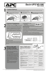
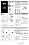
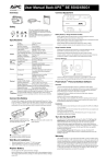
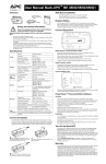
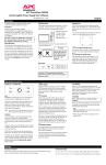
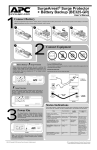
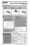
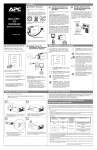
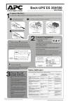
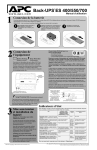
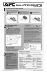
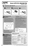
Back-UPS ES 650
®
®
User’s Guide
w w w.apc.com
1
2
Connect Battery
For safety, the Back-UPS ES is shipped with one battery wire disconnected. The UPS will not operate until the wire is connected to the touch-safe
battery terminal. NOTE: Small sparks may occur during battery connection. This is normal.
1
2
Turn the Back-UPS ES over and press in the
release tab. Slide the plastic battery cover
off of the Back-UPS.
Connect Equipment
Battery Backup
These outlets are powered whenever the Back-UPS ES is
switched ON. During a power outage or other utility problems
(brownouts, over-voltages), these outlets will be powered for a
limited time by the Back-UPS ES. Plug your computer,
monitor, CD-ROM drive or other data-sensitive devices such as
an external disk or tape drive, or Home Phoneline Networking
Association (HPNA) device into these outlets.
®
Battery Backup
Surge Protection
AC LINE
CORD
Plug the Back-UPS ES power cord directly into a wall outlet; not a surge
protector or power strip.
Connect Computer Cable
The supplied cable and software provide automatic file saving and shutdown of the
operating system in the case of a sustained power outage.
Connect the cable to the Data Port of the Back-UPS ES. Connect the other end of the
cable to the USB port on your computer. The software will automatically find the USB
Port of your computer.
Connect Modem / Phone / DSL / Fax / 10/100Base-T / HPNA / Cable Modem / CATV
or DSS to Surge Protection
The Back-UPS protects a single line (2-wire) phone (including Digital Subscriber Line DSL), Home Phoneline Networking Association (HPNA) type equipment, modem, 10/100
Base-T Ethernet, or fax machines from surges when connected through the UPS as
shown in the drawing below.
The UPS also protects a cable modem, CATV converter, or DSS receiver from surges
when it is connected through the UPS coaxial connectors as shown in the drawing below.
Surge Protection Only
POWER ON/
REPLACE BATTERY
INDICATOR
Insert the battery back into the compartment.
Slide the plastic battery cover until the release
tab locks into place.
Place the Back-UPS ES to avoid:
- Direct sunlight
- Excessive heat
- Excessive humidity or contact with fluids
Surge Protection
w w w.apc.com
3
Connect the black battery wire firmly
to the negative (-) battery terminal.
Back-UPS ES
650
Power On
Replace Battery
BUILDING WIRING
FAULT INDICATOR
FROM WALL JACK
Surge Protection Only
These outlets provide full-time protection from surges even if the
Back-UPS ES is switched OFF. Plug your printer, fax machine,
scanner, or other peripherals that do not need battery power into
these outlets.
3
Power On and
Install Software
Press the ON/OFF switch to power the unit
ON.
A single short beep and the green “Power On”
indicator confirms the Back-UPS ES is on and
ready to provide protection.
The Back-UPS ES should charge for at least 16
hours to ensure sufficient runtime. The unit is
being charged whenever it is connected to utility
power, whether the unit is turned ON or OFF.
If the red Building Wiring Fault indicator (located
on the end near the power cord) is lit, your
building wiring presents a shock hazard that
should be corrected by a qualified electrician.
Install the PowerChute® Personal Edition
software
Place the PowerChute Personal Edition CDROM into your computer and follow the
installation instructions on the screen.
Building
Wiring
Fault
Wall
Outlet
DATALINE OUTPUT TO
DSL, MODEM, PHONE,
or NETWORK
(10/100BASE-T)
TO COMPUTER
USB PORT
CABLE OUTPUT TO CABLE
MODEM, CATV CONVERTER,
or DSS INPUT
CAUTION - Refer to bottom
of unit for safety markings.
Cable Out
Circut Breaker
Push to Reset
Cable In
Modem/
Phone/Fax
Data Port
CABLE INPUT FROM INTERNET
SERVICE PROVIDER (ISP),
CATV, or DSS
CIRCUIT BREAKER
PUSH TO RESET
Status Indicators
The Back-UPS ES indicates operating status using a combination of visual and audible indicators.
Use the following table to identify the status of the Back-UPS ES.
Status
Visual Indications
(Power On - Green)
(Replace Battery - Red)
Audible Indication
Alarm Terminates
When
Power On - UPS is supplying conditioned
utility power to the load.
Power On LED - ON
None
Not applicable.
On Battery - UPS is supplying battery
power to the load connected to the Battery
outlets.
Power On LED - ON (off
during beep)
Beeping 4 times every
30 seconds
UPS transfers back to
Power On operation, or
when UPS is turned off.
Low Battery Warning - UPS is supplying
battery power to the load connected to the
Battery outlets and the battery is near
exhaustion.
Power On LED - flashing
Rapid beeping (every
1/2 second)
UPS transfers back to
normal operation, or
when UPS is turned off.
Replace Battery - The battery is
disconnected.
Replace Battery LED flashing
Constant tone
UPS turned off with the
power switch.
The battery is in need of charging or is at
the end of its usual life and must be
replaced.
Power On and Replace
Battery LEDs- Flashing
(alternating)
Constant tone
Overload Shutdown - During On Battery
operation a battery power supplied outlet
overload was detected.
None
Constant tone
UPS turned off with the
power switch.
Sleep Mode - During On Battery operation
the battery power has been completely
exhausted and the UPS is waiting for utility
power to return to normal.
None
Beeping once every 4
seconds
Utility power is restored,
or if utility power is not
restored within 32
seconds, or the UPS is
turned off.
Building Wiring Fault - Your building
wiring presents a shock hazard that should
be corrected by a licensed electrician.
Building Wiring Fault LED
(red) - ON
None
UPS is unplugged, or is
plugged into a properly
wired outlet.
See the Troubleshooting section for additional assistance.
990-1989 Copyright © 2005 American Power Conversion Corp.
APC, Back-UPS and PowerChute are registered trademarks of American Power Conversion Corp.
All other trademarks are property of their respective owners.
Troubleshooting
Problem
Use the table below to solve minor Back-UPS ES installation or operation problems. Consult APC Online Technical Support or call APC
Technical Support for assistance with problems that cannot be resolved using the table below:
Probable Cause
Solution
Back-UPS ES will not turn on.
Battery is disconnected or utility power is not available at
the wall outlet.
Connect the battery (see Connect Battery) and ensure power is available at the wall
outlet.
No power available at the Surge Protection
Only outlets.
Surge Protection Only outlets have been overloaded.
Reduce the amount of equipment plugged into Surge Protection Only outlets.
Utility power not available at the wall outlet.
Ensure the fuse or circuit breaker for the outlet is not tripped, and that the wall switch
controlling the outlet (if any) is in the ON position.
Equipment is connected to the Surge Protection Only
outlets.
Ensure the equipment you want to stay powered during a power failure is plugged
into the “Battery Backup/Surge Protection” outlets and NOT the Surge Protection
Only outlets.
The Back-UPS ES is overloaded.
Make sure the equipment plugged into the outlets of the unit are not overloading its
capacity. Try removing some of the equipment and see if the problem continues.
PowerChute Personal Edition software has performed a
shutdown due to a power failure.
The Back-UPS ES is operating normally.
The Back-UPS ES has exhausted its available battery
power.
The Back-UPS ES can only operate on battery power for a limited amount of time.
The unit will eventually turn off when the available battery power has been used.
Allow the unit to recharge for 16 hours before expecting maximum runtime.
Connected equipment does not accept the stepapproximated sine waveform the Back-UPS ES.
The output waveform is designed for computers and computer-related equipment. It
is not designed for use with motor-type equipment.
The Back-UPS ES may require service.
Contact APC Technical Support for further troubleshooting.
The Power On indicator is lit and the BackUPS ES is beeping four times every 30
seconds.
The Back-UPS ES is using battery.
The Back-UPS ES is operating normally and using battery power. Once On Battery,
you should save your current work, power down your equipment, and turn the unit
OFF. Once normal power is restored, you may turn the unit back ON and power
your equipment.
The Power On indicator flashes and the BackUPS beeps twice per second at the same time.
Battery capacity is low (about 2 minutes of use remaining).
The Back-UPS ES is about to shut off due to a low battery charge condition! When
the unit beeps twice every second, the battery has about 2 minutes of power
remaining. Immediately power down your computer and turn the unit OFF. When
normal power returns, the unit will recharge the battery.
Building Wiring Fault indicator is lit.
Your building wiring presents a shock hazard. Using the
Back-UPS with this condition will void the warranty.
Call a qualified electrician for service.
Inadequate runtime.
The battery is not fully charged.
Allow the unit to charge by leaving it plugged into the wall at least 16 hours.
Battery is near the end of useful life.
As a battery ages, the amount of runtime available will decrease. You can replace
the battery by ordering one at www.apc.com. Batteries also age prematurely if the
Back-UPS ES is placed near excessive heat.
No phone/fax/DSL/cable or network signal
from the Back-UPS.
Data line from the ISP or wall outlet is connected to the
wrong jack on the Back-UPS.
Make sure the data line from the wall outlet is connected to the jack labeled “Wall
Outlet (Phone/Fax/DSL), or “Cable In” (Cable/DSS/CATV).
Internet connection is lost during power
outage.
Modem has lost AC Power.
Plug the AC power cord of the modem into one of the four “Battery Backup/Surge
Protection” outlets.
Connected equipment loses power.
Specifications
Item
Input
Specification
Voltage
Frequency
Output
88 Vrms, typical
139 Vrms, typical
UPS Capacity (4 outlets)
650 VA / 390 W
Total Amperage (8 outlets)
12 Amps (including UPS output)
Voltage
On Battery
115 Vrms + 8%
(step-approximated sine wave)
Transfer Time
Phone/fax/DSL Surge
Protection
50-60 Hz + 1 Hz
6 ms typical, 10 ms maximum
Full time, 375 joules
Single line (2-wire)
Replace with an APC qualified battery. Replacement batteries can be ordered from
www.apc.com (valid credit card required). The replacement battery part number for
this Back-UPS is: RBC17.
Warranty
The standard warranty is 3 years from the date of purchase. APC’s standard
procedure is to replace the original unit with a factory reconditioned unit. Customers
who must have the original unit back due to assigned asset tags and set depreciation
schedules must declare such a need at first contact with APC Technical Support. APC
will ship the replacement unit once the defective unit is received by the repair
department or cross-ship upon the provision of a valid credit card number. The
customer pays for shipping to APC, and APC pays ground freight transportation costs
back to the customer.
Service
Please DO NOT RETURN Back-UPS ES to the place of purchase under any
circumstances.
Cable/CATV/DSS Surge
Protection
One Coax Input/Output
1. Consult the Troubleshooting section to eliminate common problems.
Network Surge Protection
10/100Base-T Ethernet
2. Verify the battery is connected (see Connect Battery) and that the Circuit Breaker is
not tripped (see Troubleshooting section).
EMI/RFI Filter
AC Input
Type
Average Life
Net Weight
Full time
Resettable circuit breaker
Sealed, maintenance-free lead acid
3 - 5 years depending on the number of discharge cycles
and environmental temperature
16 lbs. (7 kg.)
Dimensions (H x W x D)
3.8" x 10.9" x 7.1"
(9.6 x 27.7 x 18.0 cm)
Operating Temperature
+32oF to 104oF (0oC to 40oC)
Storage Temperature
+5oF to 113oF (-15oC to 45oC)
Operating Relative Humidity
Operating Elevation
Safety and
Regulatory
120 Vrms Nominal
50 - 60 Hz (auto-sensing)
Brownout Transfer
Protection and AC Surge Protection
Filter
Physical
Model BE650R
Over-voltage Transfer
Frequency - On Battery
Battery
Order Replacement Battery
0 to 95% non-condensing
0 to 10,000 ft (0 to 3,000m)
Safety Approvals
UL 1778 listed, cUL certified per
CSA standard C22.2 No. 107.1, NOM-001
EMC Compliance
Notice: This device complies with part 68 and part 15 of
the FCC rules. Operation is subject to the following two
conditions: (1) This device may not cause harmful
interference, and (2) This device must accept any
interference received, including interference that may
cause undesired operation.
On the bottom of this equipment is a label that contains,
among other information, the FCC registration number
and ringer equivalence number (REN) for this equipment.
If requested, this information must be provided to the
telephone company.
If you still have problems or questions, please contact APC via the internet or at one of
the phone numbers listed below.
3. Before contacting APC, please be sure to record the date purchased, UPS model,
and serial number (on bottom of unit).
4. Be prepared to troubleshoot the problem over the telephone with a Technical
Support Representative. If this is not successful, the representative will issue a Return
Material Authorization Number (RMA#) and a shipping address.
5. Pack the unit in its original packaging. If the original packaging is not available, ask
APC Technical Support about obtaining a new set. Pack the unit properly to avoid
damage in transit. Never use foam beads for packaging. Damage sustained in transit
is not covered under warranty (insuring the package for full value is recommended).
6. Write the RMA# on the outside of the package.
7. Return the unit by insured carrier to the address given to you by APC Technical
Support.
APC Contact Information
Online Technical Support:
Web Site:
USA/Canada:
Mexico:
Brazil:
Worldwide:
6.0" (152 mm)
Wall Mounting Template
Gabarit de fixation murale
Plantilla para montaje en la pared
http://support.apc.com
http://www.apc.com/support
[email protected]
www.apc.com
1.800.800.4272
+52.292.0253 / 52.292.0255
+0800.12.72.1
+1.401.789.5735