1
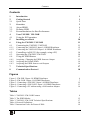
Kramer Electronics, Ltd. USER MANUAL Models: VM-28H, 2 Input 1:8 HDMI Distributor VM-216H, 2 Input 1:16 HDMI Distributor Contents Contents 1 2 2.1 3 3.1 3.2 3.3 4 4.1 5 6 6.1 Introduction Getting Started Quick Start Overview About HDMI Defining EDID Recommendations for Best Performance Your VM-28H / VM-216H Using the IR Transmitter Installing on a Rack Using the VM-28H / VM-216H Connecting the VM-28H / VM-216H 1 1 2 3 4 5 5 5 9 10 11 11 6.1.1 6.1.2 Connecting the VM-28H 2 Input 1:8 HDMI Distributor Connecting the VM-216H 2 Input 1:16 HDMI Distributor 12 13 6.2 6.3 6.4 Controlling via RS-232 (for example, using a PC) Operating the VM-28H / VM-216H Using the EDID Button 14 14 15 6.4.1 6.4.2 6.4.3 Acquiring / Changing the EDID from one Output Acquiring the Default EDID Acquiring the EDID from several Outputs 15 16 16 7 8 Technical Specifications Communication Protocol 17 18 Figures Figure 1: VM-28H 2 Input 1:8 HDMI Distributor Figure 2: VM-216H 2 Input 1:16 HDMI Distributor Figure 3: Connecting a VM-28H 2 Input 1:8 HDMI Distributor Figure 4: Connecting a VM-216H 2 Input 1:16 HDMI Distributor Figure 5: Connecting a PC without using a Null-modem Adapter 6 7 12 13 14 Tables Table 1: VM-28H / VM-216H Features Table 2: The EDID Modes Table 3: VM-28H / VM-216H Technical Specifications Table 4: Protocol Definitions Table 5: Instruction Codes for Protocol 2000 8 15 17 18 19 i Introduction 1 Introduction Welcome to Kramer Electronics! Since 1981, Kramer Electronics has been providing a world of unique, creative, and affordable solutions to the vast range of problems that confront the video, audio, presentation, and broadcasting professional on a daily basis. In recent years, we have redesigned and upgraded most of our line, making the best even better! Our 1,000-plus different models now appear in 11 groups 1 that are clearly defined by function. Congratulations on purchasing your Kramer VM-28H 2 Input 1:8 HDMI 2 Distributor and/or VM-216H 2 Input 1:16 HDMI Distributor! Each machine is ideal for: • Home theater, presentation and multimedia applications • Rental and staging Note, that the Kramer VM-28H is identical to the VM-28HDMI, and similarly, the Kramer VM-216H is identical to the VM-216HDMI; just the name has changed replacing the suffix “HDMI” by “H” (according to the HDMI Guideline). The package includes the following items: • VM-28H and/or VM-216H • Power cord • Infrared remote control transmitter (including the required batteries and a separate user manual3) • This user manual 3 2 Getting Started We recommend that you: • Unpack the equipment carefully and save the original box and packaging materials for possible future shipment • Review the contents of this user manual • Use Kramer high performance high resolution cables 4 1 GROUP 1: Distribution Amplifiers; GROUP 2: Switchers and Matrix Switchers; GROUP 3: Control Systems; GROUP 4: Format/Standards Converters; GROUP 5: Range Extenders and Repeaters; GROUP 6: Specialty AV Products; GROUP 7: Scan Converters and Scalers; GROUP 8: Cables and Connectors; GROUP 9: Room Connectivity; GROUP 10: Accessories and Rack Adapters; GROUP 11: Sierra Products 2 High-Definition Multimedia Interface 3 Download up-to-date Kramer user manuals from the Internet at this URL: http://www.kramerelectronics.com 4 The complete list of Kramer cables is on our Web site at http://www.kramerelectronics.com 1 Getting Started 2.1 Quick Start This quick start chart summarizes the basic setup and operation 1: 1 This quick start applies both to theVM-28H and the VM-216H 2 KRAMER: SIMPLE CREATIVE TECHNOLOGY Overview 3 Overview The Kramer VM-28H 2 Input 1:8 HDMI Distributor and VM-216H 2 Input 1:16 HDMI Distributor are high quality distributors that accept one of two HDMI inputs and distribute the signal to four outputs, allowing one or more of the outputs to be connected to receiving devices, thus making them a versatile, reliable component in a video system. The VM-28H / VM-216H distributes signals having resolutions up to UXGA (1600x1200), including all HDTV formats. Each high quality HDMI Distributor accepts one of two HDMI inputs, and distributes the selected signal to: • 8 outputs (the VM-28H) • 16 outputs (the VM-216H) Both machines—the VM-28H and VM-216H: • Support for up to 2.25Gbps bandwidth per graphic channel 1 • Can read and store, in non-volatile memory 2, the EDID 3 block, for each input separately, from an output display device, so it can then provide the EDID information to the HDMI source even if the display device is not connected • Let you acquire the EDID from one output, from several connected outputs or acquire the default EDID for fast and efficient connection of the unit 4 • Have a 19" 1U rack-mountable enclosure, and are fed from a 100-240 VAC universal switching power supply 1 Suitable for resolutions up to UXGA (1600x1200) at 60Hz, and for all HD resolutions 2 While the machine is ON 3 EDID is Extended Display Identification Data (see section 3.1 for a detailed definition) 4 Lets you use the EDID default value when no display from which to read the EDID is connected 3 Overview 3.1 About HDMI High-Definition Multimedia Interface (HDMI) is an uncompressed all-digital 1 audio/video interface, widely supported in the entertainment and home cinema industry. It delivers the highest high-definition image and sound quality. In particular, HDMI 2: Provides a simple 3 interface between any audio/video source, such as a set-top box, DVD player, or A/V receiver and video monitor, such as a digital flat LCD / plasma television (DTV), over a single lengthy 4 cable Supports standard, enhanced, high-definition video, and multi-channel digital audio 5 on a single cable Transmits all ATSC HDTV standards and supports 8-channel digital audio, with bandwidth to spare to accommodate future enhancements and requirements Benefits consumers by providing superior, uncompressed digital video quality via a single cable 6, and user-friendly connector Is backward-compatible with DVI (Digital Visual Interface) Supports two-way communication between the video source (such as a DVD player) and the digital television, enabling new functionality such as automatic configuration and one-button play HDMI has the capacity to support: Existing high-definition video formats (720p, 1080i, and 1080p/60), as well as standard definition formats such as NTSC or PAL 1 Ensuring an all-digital rendering of video without the losses associated with analog interfaces and their unnecessary digitalto-analog conversions 2 HDMI, the HDMI logo and High-Definition Multimedia Interface are trademarks or registered trademarks of HDMI licensing LLC 3 With video and multi-channel audio combined into a single cable, the cost, complexity, and confusion of multiple cables currently used in A/V systems is reduced 4 HDMI technology has been designed to use standard copper cable construction at up to 15m 5 HDMI supports multiple audio formats, from standard stereo to multi-channel surround-sound. HDMI has the capacity to support Dolby 5.1 audio and high-resolution audio formats 6 HDMI provides the quality and functionality of a digital interface while also supporting uncompressed video formats in a simple, cost-effective manner 4 KRAMER: SIMPLE CREATIVE TECHNOLOGY Your VM-28H / VM-216H 3.2 Defining EDID The Extended Display Identification Data (EDID 1) is a data-structure, provided by a display, to describe its capabilities to an HDMI source. The EDID enables the VM-28H / VM-216H to “know” what kind of monitor is connected to the output. The EDID includes the manufacturer’s name, the product type, the timing data supported by the display, the display size, luminance data and (for digital displays only) the pixel mapping data. 3.3 Recommendations for Best Performance To achieve the best performance: • Connect only good quality connection cables, thus avoiding interference, deterioration in signal quality due to poor matching, and elevated noise levels (often associated with low quality cables) • Avoid interference from neighboring electrical appliances and position your VM-28H / VM-216H away from moisture, excessive sunlight and dust 4 Your VM-28H / VM-216H Figure 1 illustrates the VM-28H, Figure 2 illustrates the VM-216H and Table 1 defines the front and rear panels. 1 Defined by a standard published by the Video Electronics Standards Association (VESA) 5 Your VM-28H / VM-216H Figure 1: VM-28H 2 Input 1:8 HDMI Distributor 6 KRAMER: SIMPLE CREATIVE TECHNOLOGY Your VM-28H / VM-216H Figure 2: VM-216H 2 Input 1:16 HDMI Distributor 1 1 The remote IR opening, item 12, is not included in this machine 7 Your VM-28H / VM-216H Table 1: VM-28H / VM-216H Features # Feature Function IR Receiver 2 3 POWER Switch 1 IN 1 Button 4 SELECT 1 1 IN 2 Button 5 6 7 EDID Button 2 3 LOCK Button OUTPUT STATUS LEDs 8 9 10 11 RS-232 9-pin D-sub Port INPUT 1 HDMI Connector INPUT 2 HDMI Connector OUTPUT HDMI Connector 12 13 The red LED is illuminated when receiving signals from the Kramer Infrared remote control transmitter Illuminated switch for turning the unit ON or OFF Press to select source 1 and distribute this signal to the outputs (when the EDID button does not illuminate) Also used for acquiring/changing the EDID (see section 6.4) Press to select source 2 and distribute this signal to the outputs (when the EDID button does not illuminate) Also used for acquiring/changing the EDID (see section 6.4) Press for more than 3 seconds to set to the EDID mode Press to engage/disengage the front panel switches LEDs light when an output(s) is connected and active; LEDs blink when selecting the EDID (see section 6.4) or when connecting a non-HDCP display while providing HDCP content to the VM-28H / VM-216H 4 Connects to the PC or the Remote Controller Connects to the HDMI source 1 Connects to the HDMI source 2 Connects to the HDMI acceptor [from 1 to 8 (for the VM-28H), from 1 to 16 (for the VM-216H)] 5 REMOTE IR Opening (for the Connects to an external IR receiver unit for controlling the machine via VM-28H) an IR remote controller instead of using the front panel IR receiver 6 Power Connector with Fuse AC connector enabling power supply to the unit 1 Illuminates when selected and there is a signal, blinks when selected but there is no signal 2 Illuminates when configuring the EDID. When the EDID button does not illuminate the machine is in Distribution mode (lets you distribute an input signal to the outputs) 3 Illuminates when the front panel switches are locked, pressing another button causes the LOCK button to blink once warning that you need to unlock to regain control via the front panel. The LOCK button also blinks (the IN 1, IN 2 and EDID buttons do not blink at the same time) when the machine is busy (perhaps searching between signals) and no operation is permitted 4 Via a null-modem connection 5 Covered by a cap. The 3.5mm connector at the end of the internal IR connection cable fits through this opening 6 Optional. Can be used instead of the front panel (built-in) IR receiver to remotely control the machine (only if the internal IR connection cable has been installed) 8 KRAMER: SIMPLE CREATIVE TECHNOLOGY Your VM-28H / VM-216H 4.1 Using the IR Transmitter You can use the RC-IR2 IR transmitter to control the machine via the built-in IR receiver on the front panel or, instead, via an optional external IR receiver 1. The external IR receiver can be located 15 meters away from the machine. This distance can be extended to up to 60 meters when used with three extension cables 2. Before using the external IR receiver, be sure to arrange for your Kramer dealer to insert the internal IR connection cable 3 Connect the external IR receiver to the REMOTE IR 3.5mm connector. 1 Model: C-A35M/IRR-50 2 Model: C-A35M/A35F-50 3 P/N: 505-70434010-S 9 Installing on a Rack 5 Installing on a Rack This section describes what to do before installing in a rack and how to rack mount. with the 3.5mm connector that fits into the REMOTE IR opening on the rear panel. 10 KRAMER: SIMPLE CREATIVE TECHNOLOGY Using the VM-28H / VM-216H 6 Using the VM-28H / VM-216H This section describes how to: • Connect the VM-28H / VM-216H, see section 6.1 • Control the VM-28H / VM-216H via RS-232, see section 6.2 • Operate the VM-28H / VM-216H, see section 6.3 • Use the EDID button, see section 6.4 6.1 Connecting the VM-28H / VM-216H This section describes how to connect the: • VM-28H, see section 6.1.1 • VM-216H, see section 6.1.2 11 Using the VM-28H / VM-216H 6.1.1 Connecting the VM-28H 2 Input 1:8 HDMI Distributor To connect the VM-28H, as the example in Figure 3 shows, do the following1: 1. Connect the HDMI OUTPUT connectors2 to up to 8 HDMI acceptors, using Kramer HDMI copper cables. In this example 3, connect the: OUTPUT 1 connector to acceptor 1 (for example, a plasma display) OUTPUT 2 connector to acceptor 2 (for example, an LCD TV) OUTPUT 7 connector to acceptor 7 (for example, an LCD TV) OUTPUT 8 connector to acceptor 8 (for example, a plasma display) 2. Connect the two HDMI sources, for example, a DVD player and a set top box, to the INPUT 1 and INPUT 2 connectors, respectively, using the Kramer HDMI copper cables. 3. If required, connect a PC and/or controller to the RS-232 port (see section 6.2). 4. Connect the power cord to the mains electricity. Figure 3: Connecting a VM-28H 2 Input 1:8 HDMI Distributor 1 Switch OFF the power on each device before connecting it to your VM-28H. After connecting your VM-28H, switch on its power and then switch on the power on each device 2 As required. Up to 8 outputs can be connected. Not all outputs need to be connected 3 Only connections from the first two acceptors and the last two acceptors are shown in Figure 3 12 KRAMER: SIMPLE CREATIVE TECHNOLOGY Using the VM-28H / VM-216H 6.1.2 Connecting the VM-216H 2 Input 1:16 HDMI Distributor To connect the VM-216H, as the example in Figure 4 shows, do the following 1: 1. Connect the HDMI OUTPUT connectors2 to up to 16 HDMI acceptors, using Kramer HDMI copper cables. In this example 3, connect the: OUTPUT 1 connector to acceptor 1 (for example, a plasma display) OUTPUT 2 connector to acceptor 2 (for example, an LCD TV) OUTPUT 15 connector to acceptor 15 (for example, an LCD TV) OUTPUT 16 connector to acceptor 16 (for example, a plasma display) 2. Connect the two HDMI sources, for example, a DVD player and a set top box, to the INPUT 1 and INPUT 2 connectors, respectively, using the Kramer HDMI copper cables. 3. If required, connect a PC and/or controller to the RS-232 port (see section 6.2). 4. Connect the power cord to the mains electricity. Figure 4: Connecting a VM-216H 2 Input 1:16 HDMI Distributor 1 Switch OFF the power on each device before connecting it to your VM-216H. After connecting your VM-216H, switch on its power and then switch on the power on each device 2 As required. Up to 16 outputs can be connected. Not all outputs need to be connected 3 Only connections from the first two acceptors and the last two acceptors are shown in Figure 4 13 Using the VM-28H / VM-216H 6.2 Controlling via RS-232 (for example, using a PC) You can connect a PC (or other controller) to the VM-28H / VM-216H via the RS-232 port. To connect using the Null-modem adapter provided with the machine (recommended method): • Connect the RS-232 9-pin D-sub rear panel port on the VM-28H / VM-216H to the Null-modem adapter and connect the Null-modem adapter with a 9-wire flat cable to the RS-232 9-pin D-sub port on your PC To connect without using a Null-modem adapter: • Connect the RS-232 9-pin D-sub port on your PC to the RS-232 9-pin D-sub rear panel port on the VM-28H / VM-216H, as Figure 5 illustrates PIN 5 Connected to PIN 5 (Ground) PIN 3 Connected to PIN 2 PIN 2 Connected to PIN 3 9-pin D-sub (From PC) 9-pin D-sub (Male) PIN 4 is connected to PIN 6 PINs 8, 7, 1 are connected together If a shielded cable is used, connect the shield to PIN 5 Figure 5: Connecting a PC without using a Null-modem Adapter 6.3 Operating the VM-28H / VM-216H To operate the VM-28H / VM-216H: 1. Turn ON the POWER. 2. Select the desired input. 3. Press the EDID button to acquire or change the EDID data (see section 6.4). 14 KRAMER: SIMPLE CREATIVE TECHNOLOGY Using the VM-28H / VM-216H 6.4 Using the EDID Button Initially, the VM-28H / VM-216H operates with the factory default EDID. You can acquire the EDID from: • One Output (the selected output LED blinks) • The Default EDID (all the output LEDs blink) • Several Connected Outputs, the Auto-mix Mode 1 (the output LEDs blink in sequence) To cycle between the different modes (One Output, Default and Auto-mix), press the input button (IN 1 or IN 2) to which you want to read the EDID, as defined in Table 2. Table 2: The EDID Modes Current EDID Mode Appearance One output The selected output LED blinks Default The output LEDs blink Auto-mix The output LEDs blink in sequence To cycle to the Default EDID To cycle to the Automix EDID To cycle to the One output EDID Press the IN button once again after selecting output 8 (for VM-28H) or output 16 (for VM-216H). The output LEDS blink Press the IN button once Press the IN button to select the required output. The selected output blinks To acquire or change the EDID of a new output display from: • One output, see section 6.4.1 • The default EDID, see section 6.4.2 • Several connected outputs, see section 6.4.3 6.4.1 Acquiring / Changing the EDID from one Output To acquire or change the EDID of a new output display: 1. Connect the power supply. 2. Connect the new output display device. 3. Press the EDID button for more than 3 seconds. 1 The EDID acquired is a weighted average of all the connected outputs. For example, if several displays with different resolutions are connected to the outputs, the acquired EDID supports all the resolutions, as well as other parameters included in the EDID 15 Using the VM-28H / VM-216H 4. Press an input button (either IN 1 or IN 2) once 1. The selected input button illuminates. 5. Enter the One output mode as defined in Table 2 (with either IN 1 or IN 2). 6. Press that input button to set the appropriate OUTPUT STATUS LED. The OUTPUT STATUS LED blinks indicating that that output channel is selected. 7. Press the LOCK button to copy the EDID of the selected OUTPUT to the input. Note: to cancel the EDID modification, press the EDID button before pressing the LOCK button. While the EDID is being copied the EDID button blinks. The new EDID is copied, when the EDID button no longer blinks. 6.4.2 Acquiring the Default EDID To reset the default EDID, do the following: 1. Connect the power supply. 2. Press the EDID button for more than 3 seconds. 3. Press an input button (either IN 1 or IN 2)1 once. The selected input button illuminates. 4. Enter the default mode as defined in Table 2 (with either IN 1 or IN 2). All the OUTPUT STATUS LEDs blink simultaneously. 5. Press the LOCK button to copy the default EDID to the input. Note: to cancel the EDID modification, press the EDID button before pressing the LOCK button. While the EDID is being copied the EDID button blinks. The new EDID is copied, when the EDID button no longer blinks. 6.4.3 Acquiring the EDID from several Outputs To acquire or change an EDID via several connected outputs: 1. Connect the power supply. 2. Connect several output display devices. 3. Press the EDID button for more than 3 seconds. 4. Press an input button (either IN 1 or IN 2)1 once. The selected input button illuminates. 1 Depending if you want to copy the new EDID to input 1 or to input 2 16 KRAMER: SIMPLE CREATIVE TECHNOLOGY Technical Specifications 5. Enter the Auto-mix mode as defined in Table 2 (with either IN 1 or IN 2). The OUTPUT STATUS LEDs blink in sequence. 6. Press the LOCK button to copy the EDID of the selected OUTPUT to the input. Note: to cancel the EDID modification, press the EDID button before pressing the LOCK button. While the EDID is being copied the EDID button blinks. The new EDID is copied, when the EDID button no longer blinks. 7 Technical Specifications Table 3 includes the technical specifications 1 of the VM-28H and VM-216H: Table 3: VM-28H / VM-216H Technical Specifications INPUTS: OUTPUTS: BANDWIDTH: COMPLIANCE WITH HDMI STANDARD: CONTROLS: INDICATOR LEDs: POWER SOURCE: DIMENSIONS: WEIGHT: ACCESSORIES: OPTIONS: VM-28H VM-216H 2 HDMI Connector 2 HDMI Connector 8 HDMI Connectors 16 HDMI Connectors Supports up to 2.25Gbps bandwidth per graphic channel Supports HDMI 1.3 and HDCP EDID, IN 1, IN 2 and, LOCK buttons, RS-232, infrared remote control OUTPUT STATUS LEDs 100-240V AC, 50/60Hz 35VA 100-264V AC 50/60Hz 31VA 19-inch (W), 7-inch (D), 1U (H) rack mountable 2.5kg (5.5lbs) approx. Power cord Kramer HDMI cables 2, External remote IR receiver cable 3 1 Specifications are subject to change without notice 2 For best results, use Kramer cables such as the C-HM/HM series, the C-HM/DM series and/or our HDMI over fiber optics C-FOHM/FOHM series 3 P/N: C-A35M/IRR-50 17 Communication Protocol 8 Communication Protocol The VM-28H/VM-216H is compatible with Kramer’s Protocol 2000 (version 0.48) (below). This RS-232/RS-485 communication protocol uses four bytes of information as defined below. For RS-232, a null-modem connection between the machine and controller is used. The default data rate is 9600 baud, with no parity, 8 data bits and 1 stop bit. Table 4: Protocol Definitions MSB LSB DESTINATION 0 7 1st byte D 6 INSTRUCTION N5 5 N4 4 N3 3 N2 2 N1 1 N0 0 I5 5 I4 4 I3 3 I2 2 I1 1 I0 0 O4 4 O3 3 O2 2 O1 1 O0 0 M2 2 M1 1 M0 0 INPUT 1 7 2nd byte I6 6 OUTPUT 1 7 3rd byte O6 6 O5 5 1 7 4th byte OVR 6 X 5 MACHINE NUMBER M4 4 M3 3 1st BYTE: Bit 7 – Defined as 0. D – “DESTINATION”: 0 - for sending information to the switchers (from the PC); 1 - for sending to the PC (from the switcher). N5…N0 – “INSTRUCTION” The function that is to be performed by the switcher(s) is defined by the INSTRUCTION (6 bits). Similarly, if a function is performed via the machine’s keyboard, then these bits are set with the INSTRUCTION NO., which was performed. The instruction codes are defined according to the table below (INSTRUCTION NO. is the value to be set for N5…N0). 2nd BYTE: Bit 7 – Defined as 1. I6…I0 – “INPUT”. When switching (ie. instruction codes 1 and 2), the INPUT (7 bits) is set as the input number which is to be switched. Similarly, if switching is done via the machine’s front-panel, then these bits are set with the INPUT NUMBER which was switched. For other operations, these bits are defined according to the table. 3rd BYTE: Bit 7 – Defined as 1. O6…O0 – “OUTPUT”. When switching (ie. instruction codes 1 and 2), the OUTPUT (7 bits) is set as the output number which is to be switched. Similarly, if switching is done via the machine’s front-panel, then these bits are set with the OUTPUT NUMBER which was switched. For other operations, these bits are defined according to the table. 4th BYTE: Bit 7 – Defined as 1. Bit 5 – Don’t care. OVR – Machine number override. M4…M0 – MACHINE NUMBER. Used to address machines in a system via their machine numbers. When several machines are controlled from a single serial port, they are usually configured together with each machine having an individual machine number. If the OVR bit is set, then all machine numbers will accept (implement) the command, and the addressed machine will reply. For a single machine controlled via the serial port, always set M4…M0 = 1, and make sure that the machine itself is configured as MACHINE NUMBER = 1. 18 KRAMER: SIMPLE CREATIVE TECHNOLOGY Communication Protocol Table 5: Instruction Codes for Protocol 2000 Note: All values in the table are decimal, unless otherwise stated. INSTRUCTION DEFINITION FOR SPECIFIC INSTRUCTION # INPUT DESCRIPTION 1 SWITCH VIDEO 30 LOCK FRONT PANEL 31 61 REQUEST WHETHER PANEL IS LOCKED IDENTIFY MACHINE 62 DEFINE MACHINE NOTE OUTPUT Set equal to video input which is to be switched (0 = disconnect) 0 - Panel unlocked 1 - Panel locked 0 Set equal to video output which is to be switched (0 = to all the outputs) 0 2, 15 0 16 1 - video machine name 2 - audio machine name 3 - video software version 4 - audio software version 5 - RS422 controller name 6 - RS422 controller version 7 - remote control name 8 - remote software version 9 - Protocol 2000 revision 1 - number of inputs 2 - number of outputs 3 - number of setups 0 - Request first 4 digits 1 - Request first suffix 2 - Request second suffix 3 - Request third suffix 10 - Request first prefix 11 - Request second prefix 12 - Request third prefix 13 1 - for video 2 - for audio 3 - for SDI 4 - for remote panel 5 - for RS-422 controller 14 2 NOTES on the above table: NOTE 2 - These are bi-directional definitions. That is, if the switcher receives the code, it will perform the instruction; and if the instruction is performed (due to a keystroke operation on the front panel), then these codes are sent. For example, if the HEX code 01 85 88 83 was sent from the PC, then the switcher (machine 3) will switch input 5 to output 8. If the user switched input 1 to output 7 via the front panel keypad, then the switcher will send HEX codes: 41 81 87 83 to the PC. When the PC sends one of the commands in this group to the switcher, then, if the instruction is valid, the switcher replies by sending to the PC the same four bytes that it was sent (except for the first byte, where the DESTINATION bit is set high). NOTE 13 - This is a request to identify the switcher/s in the system. If the OUTPUT is set as 0, and the INPUT is set as 1, 2, 5 or 7, the machine will send its name. The reply is the decimal value of the INPUT and OUTPUT. For example, for a 2216, the reply to the request to send the audio machine name would be (HEX codes): 7D 96 90 81 (i.e. 128dec+ 22dec for 2nd byte, and 128dec+ 16dec for 3rd byte). If the request for identification is sent with the INPUT set as 3 or 4, the appropriate machine will send its software version number. Again, the reply would be the decimal value of the INPUT and OUTPUT - the INPUT representing the number in front of the decimal point, and the OUTPUT representing the number after it. For example, for version 3.5, the reply to the request to send the version number would be (HEX codes): 7D 83 85 81 (i.e. 128dec+ 3dec for 2nd byte, 128dec+ 5dec for 3rd byte). If the OUTPUT is set as 1, then the ASCII coding of the lettering following the machine’s name is sent. For example, for the VS-7588YC, the reply to the request to send the first suffix would be (HEX codes): 7D D9 C3 81 (i.e. 128dec+ ASCII for “Y”; 128dec+ ASCII for “C”). NOTE 14 - The number of inputs and outputs refers to the specific machine which is being addressed, not to the system. For example, if six 16X16 matrices are configured to make a 48X32 system (48 inputs, 32 outputs), the reply to the HEX code 3E 82 81 82 (ie. request the number of outputs) would be HEX codes 7E 82 90 82 ie. 16 outputs NOTE 15 – When the OVR bit (4th byte) is set, then the “video” commands have universal meaning. For example, instruction 1 (SWITCH VIDEO) will cause all units (including audio, data, etc.) to switch. Similarly, if a machine is in “FOLLOW” mode, it will perform any “video” instruction. NOTE 16 - The reply to the “REQUEST WHETHER PANEL IS LOCKED” is as in NOTE 4 above, except that here the OUTPUT is assigned with the value 0 if the panel is unlocked, or 1 if it is locked. 19 LIMITED WARRANTY Kramer Electronics (hereafter Kramer) warrants this product free from defects in material and workmanship under the following terms. HOW LONG IS THE WARRANTY Labor and parts are warranted for seven years from the date of the first customer purchase. WHO IS PROTECTED? Only the first purchase customer may enforce this warranty. WHAT IS COVERED AND WHAT IS NOT COVERED Except as below, this warranty covers all defects in material or workmanship in this product. The following are not covered by the warranty: 1. Any product which is not distributed by Kramer, or which is not purchased from an authorized Kramer dealer. If you are uncertain as to whether a dealer is authorized, please contact Kramer at one of the agents listed in the Web site www.kramerelectronics.com. 2. Any product, on which the serial number has been defaced, modified or removed, or on which the WARRANTY VOID IF TAMPERED sticker has been torn, reattached, removed or otherwise interfered with. 3. Damage, deterioration or malfunction resulting from: i) Accident, misuse, abuse, neglect, fire, water, lightning or other acts of nature ii) Product modification, or failure to follow instructions supplied with the product iii) Repair or attempted repair by anyone not authorized by Kramer iv) Any shipment of the product (claims must be presented to the carrier) v) Removal or installation of the product vi) Any other cause, which does not relate to a product defect vii) Cartons, equipment enclosures, cables or accessories used in conjunction with the product WHAT WE WILL PAY FOR AND WHAT WE WILL NOT PAY FOR We will pay labor and material expenses for covered items. We will not pay for the following: 1. Removal or installations charges. 2. Costs of initial technical adjustments (set-up), including adjustment of user controls or programming. These costs are the responsibility of the Kramer dealer from whom the product was purchased. 3. Shipping charges. HOW YOU CAN GET WARRANTY SERVICE 1. To obtain service on you product, you must take or ship it prepaid to any authorized Kramer service center. 2. Whenever warranty service is required, the original dated invoice (or a copy) must be presented as proof of warranty coverage, and should be included in any shipment of the product. Please also include in any mailing a contact name, company, address, and a description of the problem(s). 3. For the name of the nearest Kramer authorized service center, consult your authorized dealer. LIMITATION OF IMPLIED WARRANTIES All implied warranties, including warranties of merchantability and fitness for a particular purpose, are limited in duration to the length of this warranty. EXCLUSION OF DAMAGES The liability of Kramer for any effective products is limited to the repair or replacement of the product at our option. Kramer shall not be liable for: 1. Damage to other property caused by defects in this product, damages based upon inconvenience, loss of use of the product, loss of time, commercial loss; or: 2. Any other damages, whether incidental, consequential or otherwise. Some countries may not allow limitations on how long an implied warranty lasts and/or do not allow the exclusion or limitation of incidental or consequential damages, so the above limitations and exclusions may not apply to you. This warranty gives you specific legal rights, and you may also have other rights, which vary from place to place. NOTE: All products returned to Kramer for service must have prior approval. This may be obtained from your dealer. This equipment has been tested to determine compliance with the requirements of: EN-50081: EN-50082: CFR-47: "Electromagnetic compatibility (EMC); generic emission standard. Part 1: Residential, commercial and light industry" "Electromagnetic compatibility (EMC) generic immunity standard. Part 1: Residential, commercial and light industry environment". FCC* Rules and Regulations: Part 15: “Radio frequency devices Subpart B Unintentional radiators” CAUTION! Servicing the machines can only be done by an authorized Kramer technician. Any user who makes changes or modifications to the unit without the expressed approval of the manufacturer will void user authority to operate the equipment. Use the supplied DC power supply to feed power to the machine. Please use recommended interconnection cables to connect the machine to other components. * FCC and CE approved using STP cable (for twisted pair products) 20 KRAMER: SIMPLE CREATIVE TECHNOLOGY For the latest information on our products and a list of Kramer distributors, visit our Web site: www.kramerelectronics.com, where updates to this user manual may be found. We welcome your questions, comments and feedback. Safety Warning: Disconnect the unit from the power supply before opening/servicing. Caution Kramer Electronics, Ltd. Web site: www.kramerelectronics.com E-mail: [email protected] P/N: 2900-000700 REV 1