1
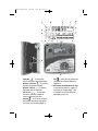
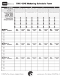
TMC424_UGE_466A
12/14/07
4:51 PM
Page i
Toro Modular Controller - 4 to 24 Stations
English
ON
PREV
NEXT
OFF
Español
%
Installation
Programming
Operation
Français
User’s Guide
TMC424_UGE_466A
1/22/08
5:00 PM
Page ii
Introduction
The TMC-424E Series takes modularity to a whole new level. Toro’s advanced
modular technology combines sophisticated features with simple operation to
provide a customizable controller. Station count can be 4 – 24 stations, using fouror eight-station modules. Real-time flow sensing monitors up to three independent
sensors and is compatible with the Toro TFS Series flow sensors. Versatile run
times allows for additional watering flexibility. Add this together with features like
two levels of surge protection, compatibility with the TMR-1 Maintenance Remote,
the rugged dual-use cabinet, and convenient program review feature, and you
really do have the ultimate in controller Flexibility.
TMC-424E controller features:
• Advanced hybrid control module featuring easy-to-use dial interface
• Non-volatile memory–retains program data without battery backup
• Four fully-independent watering programs
• Concurrent operation of up to three automatic programs
• 16 unique start times allotted to programs in any combination of 0–16
• Program cycle and soak option provides 1–30 repeat cycles and soak time
delay from 1 second to 60 minutes
• Day scheduling by Calendar days, 1–31-day Interval or Odd/Even days with
selective day exclusion
• Station run time adjustable form 1 second to 8 hours
• Season Adjust by program and by month from 0–200% (automatic split-cycle
watering for adjustment over 100%)
• Rain delay to postpone automatic watering operation from 1–14 days
• Master valve/pump start operation assignable by program or station
• Programmable well recovery/station delay from 1–60 seconds or 1–60 minutes
• Flow monitoring and alert parameters for 1– 3 flow sensors.
• Output current watchdog feature detects overload/short-circuit condition and
automatically bypasses suspect station(s).
• Optional Normally Open master valve control on flow sensing modules
• Manual operations by station and program
• Review feature quickly recaps all program information
• 12-or 24-hour time designation
• Programming display prompts selectable in English, Spanish, French,
German, Italian or Portuguese
• Valve test feature for quick station and system check
• Equipped for optional Toro rain sensor models TRS, TWRS and TWRFS,
Toro TMR-1 handheld maintenance remote and Toro TFS Series flow sensors.
ii
TMC424_UGE_466A
1/22/08
5:00 PM
Page iii
The unique TMC-424E Expansion Modules are color-coded for easy identification.
The modules can be mixed and matched in any combination and are available in
six models as indicated in the table below.
Model
Number
Color Station
Code Count
Surge
Level
Surge
Icon
Flow
Monitor
Flow Monitor
Icon
Master Valve
Control
TSM-4
Gray
4
Standard
No
No
TSM-8
Gray
4
Standard
No
No
TSM-4H
Beige
4
High
No
No
TSM-8H
Beige
4
High
No
No
TSM-4F
Blue
4
High
Yes
Yes
TSM-8F
Blue
4
High
Yes
Yes
The Expansion Modules can be installed and removed at any time without powering
down the controller. The TMC-424E will gain instant access to the module and will
logically number the stations based on module position.
For example, if three 4-station modules are installed, the stations will be numbered
1–12: module I (stations 1–4) module I I (stations 5–8) and module I I I (stations
9–12). If module I I is removed, stations 5–8 will be automatically assigned to
module I I I. All stations will remain in sequence without gaps.
Getting Started
As an initial step, we recommend that you take a few moments to browse through
various sections of this User’s Guide. Also, take the time jot down some basic
watering program and station information on the Watering Schedule form provided.
Having this information readily at hand will be very helpful during the initial controller
setup and programming procedures.
Note that the Watering Schedule form provides a convenient pocket for the User’s
Guide and Quick Reference Guide when folded and attached to the inside of the
cabinet door.
iii
TMC424_UGE_466A
1/22/08
5:00 PM
Page iv
Table of Contents
Introduction . . . . . . . . . . . . . . . . . . . . . . . . . . . . . . . . . . . . . . . . . . . . . . . . . . . .ii
Control Module Overview . . . . . . . . . . . . . . . . . . . . . . . . . . . . . . . . . . . . . . . .2
Internal Component Overview . . . . . . . . . . . . . . . . . . . . . . . . . . . . . . . . . . . . .4
Programming Overview . . . . . . . . . . . . . . . . . . . . . . . . . . . . . . . . . . . . . . . . . .5
What is a Watering Program? . . . . . . . . . . . . . . . . . . . . . . . . . . . . . . . . . . . .5
What is a Program Watering Cycle? . . . . . . . . . . . . . . . . . . . . . . . . . . . . . . .5
What is Armchair Programming TM? . . . . . . . . . . . . . . . . . . . . . . . . . . . . . . . .5
Controller Programming . . . . . . . . . . . . . . . . . . . . . . . . . . . . . . . . . . . . . . . . .6
Set Current Time and Date . . . . . . . . . . . . . . . . . . . . . . . . . . . . . . . . . . . . . .6
Select the Program . . . . . . . . . . . . . . . . . . . . . . . . . . . . . . . . . . . . . . . . . . . .6
Set Station Run Time . . . . . . . . . . . . . . . . . . . . . . . . . . . . . . . . . . . . . . . . . . .6
Set Program Start Times . . . . . . . . . . . . . . . . . . . . . . . . . . . . . . . . . . . . . . . .7
Set Watering Day Schedule . . . . . . . . . . . . . . . . . . . . . . . . . . . . . . . . . . . . .7
To Set Calendar Days . . . . . . . . . . . . . . . . . . . . . . . . . . . . . . . . . . . . . . . .8
To Set Odd or Even Days . . . . . . . . . . . . . . . . . . . . . . . . . . . . . . . . . . . . .8
To Set Interval Days . . . . . . . . . . . . . . . . . . . . . . . . . . . . . . . . . . . . . . . . .8
Season Adjust Feature . . . . . . . . . . . . . . . . . . . . . . . . . . . . . . . . . . . . . . . . . . .9
Special Functions . . . . . . . . . . . . . . . . . . . . . . . . . . . . . . . . . . . . . . . . . . . . . .10
Setting Station Delay Time Option . . . . . . . . . . . . . . . . . . . . . . . . . . . . . . .10
Setting Master Valve/Pump Start Options . . . . . . . . . . . . . . . . . . . . . . . . . .10
To Select MV/PS Operation by Program and Station . . . . . . . . . . . . . . .11
To Set MV/PS Start Delay . . . . . . . . . . . . . . . . . . . . . . . . . . . . . . . . . . . .11
To Set MV/PS Operation During Station Delay . . . . . . . . . . . . . . . . . . . .11
Setting Watering Cycle Repeat Option . . . . . . . . . . . . . . . . . . . . . . . . . . . .12
Setting Program Stack/Overlap Option . . . . . . . . . . . . . . . . . . . . . . . . . . .12
Erase Program Memory . . . . . . . . . . . . . . . . . . . . . . . . . . . . . . . . . . . . . . .13
Selecting Handheld Remote Operation . . . . . . . . . . . . . . . . . . . . . . . . . . . .13
Selecting Display Language Option . . . . . . . . . . . . . . . . . . . . . . . . . . . . . .13
12/24-hour Time Display Option . . . . . . . . . . . . . . . . . . . . . . . . . . . . . . . . .13
Selecting Run Time Format . . . . . . . . . . . . . . . . . . . . . . . . . . . . . . . . . . . . .13
iv
TMC424_UGE_466A
1/22/08
5:00 PM
Page v
Manual Operations . . . . . . . . . . . . . . . . . . . . . . . . . . . . . . . . . . . . . . . . . . . . .14
Manual Station Operations . . . . . . . . . . . . . . . . . . . . . . . . . . . . . . . . . . . . .14
True Manual Operation . . . . . . . . . . . . . . . . . . . . . . . . . . . . . . . . . . . . . .14
Timed Manual Operation . . . . . . . . . . . . . . . . . . . . . . . . . . . . . . . . . . . .14
Manual Program Operations . . . . . . . . . . . . . . . . . . . . . . . . . . . . . . . . . . . .15
Single Program Operation . . . . . . . . . . . . . . . . . . . . . . . . . . . . . . . . . . .15
Multiple Program Operation . . . . . . . . . . . . . . . . . . . . . . . . . . . . . . . . . .15
Flow Sensor Operations . . . . . . . . . . . . . . . . . . . . . . . . . . . . . . . . . . . . . . . .16
Select Fill Delay Option . . . . . . . . . . . . . . . . . . . . . . . . . . . . . . . . . . . . . . . .16
Select Flow Sensor Module Master Valve Type . . . . . . . . . . . . . . . . . . . . .17
Select Flow Rate Alert Thresholds . . . . . . . . . . . . . . . . . . . . . . . . . . . . . . .17
Rain Sensor Control Features . . . . . . . . . . . . . . . . . . . . . . . . . . . . . . . . . . .18
Rain Sensor Timed Bypass . . . . . . . . . . . . . . . . . . . . . . . . . . . . . . . . . . . . .18
Rain Sensor Control by Program . . . . . . . . . . . . . . . . . . . . . . . . . . . . . . . .19
Valve Test Feature . . . . . . . . . . . . . . . . . . . . . . . . . . . . . . . . . . . . . . . . . . . . .19
Rain Delay Feature . . . . . . . . . . . . . . . . . . . . . . . . . . . . . . . . . . . . . . . . . . . . .20
Program Review Function . . . . . . . . . . . . . . . . . . . . . . . . . . . . . . . . . . . . . . .20
Installation Instructions . . . . . . . . . . . . . . . . . . . . . . . . . . . . . . . . . . . . . . . .21
Cabinet Installation . . . . . . . . . . . . . . . . . . . . . . . . . . . . . . . . . . . . . . . . . . .21
Field Wire Connections . . . . . . . . . . . . . . . . . . . . . . . . . . . . . . . . . . . . . . . .22
Flow Sensor Connection . . . . . . . . . . . . . . . . . . . . . . . . . . . . . . . . . . . . . . .23
Power Connection – Indoor Models . . . . . . . . . . . . . . . . . . . . . . . . . . . . . .24
Power Connection – Outdoor Models . . . . . . . . . . . . . . . . . . . . . . . . . . . . .25
Rain Sensor Installation (Optional) . . . . . . . . . . . . . . . . . . . . . . . . . . . . . . .26
Toro TMR-1 Handheld Remote Installation (Optional) . . . . . . . . . . . . . . . .27
Appendix A – TFS Flow Sensor Performance Data . . . . . . . . . . . . . . . . . .28
Appendix B – TMC-424E Current Load Data . . . . . . . . . . . . . . . . . . . . . . . .29
Appendix C – Display Alerts . . . . . . . . . . . . . . . . . . . . . . . . . . . . . . . . . . . . .30
Appendix D – Default Settings - Abbreviations . . . . . . . . . . . . . . . . . . . . .31
Specifications . . . . . . . . . . . . . . . . . . . . . . . . . . . . . . . . . . . . . . . . . . . . . . . . .32
The Toro Promise - Limited Warranty Information . . . . . . . . . . . . . . . . . . .33
FCC Compliance Information . . . . . . . . . . . . . . . . . . . . . . . . . . . . . . . . . . . .36
Customer Care You Can Count On . . . . . . . . . . . . . . . . . . . . . . . . . . . . . . .36
v
TMC424_UGE_466A
1/22/08
5:00 PM
Page 2
Control Module Overview
The following brief descriptions of the controller components and display
elements are provided for general overview. Each of these items are explained
in detail within the appropriate section of this guide.
1 - Program Switch
Four-position slide switch used to
select program A, B, C and D for
set up, review and manual control.
2 - Digital Display
a - Station run time icon.
b -Start time icon.
c - Program identifiers.
d -Prompt displayed with Interval
schedule length
e - Flow sensor icon displayed with
flow sensor expansion module
f - % symbol displayed when the
Season Adjust function is active.
g -Water drop icon i n d i c a t e s
current watering activity. Icon
with slash indicates automatic
operation is disabled (Off, station
disabled or Rain Delay function.
h -Prompt displayed to indicate
current day within an Interval
watering day schedule.
i - Expansion module dock identifier
(I, I I and I I I, left to right).
j - Hollow circles represent the
station terminals of an installed
4-or 8-station expansion module.
Station positions of the current
operating station or stations
assigned to a program are
indicated by a solid circle.
k - Indicates the station number or
start time number is currently
shown in the 2-digit numeric
display (directly above).
2
l - 2-digit display identifies the
station number or start time
number currently selected.
3 - Navigation Buttons
The
and
buttons are used
to select function menu items.
All numeric, On/Off, and Yes/No
values are selected with the
and
buttons.
4 - Function Dial
Turns in either direction to select
the following operating, control,
and programming functions:
– The normal position for
automatic controller operations.
CURRENT TIME/DAY
– To set
clock time, day and date.
RUN
– To set station
STATION TIMES
run time.
START TIMES
– To set program
start times.
– To set
program watering day schedule
by days of the week.
ODD/EVEN
– To set program
watering day schedule by Odd
or Even numbered days.
CALENDAR DAYS
– To adjust run
time of all stations within a program
and/or program within a month
from 0 to 200% in 10% increments.
SPECIAL FUNCTIONS
– To select
specialized setup and programming
options (see page 10 for details).
SEASON ADJUST
TMC424_UGE_466A
1/22/08
5:00 PM
Page 3
c
e
d
g
f
h
b
i
a
1
2
l
3
j
k
5
4
– To select flow
sensor operation setup parameters.
SENSORS
– To operate
watering programs manually.
MANUAL STATION
– To operate
individual stations manually.
MANUAL PROGRAM
– To manually
test valve operating sequence
using a temporary run time.
REVIEW
– To recap all program
information including: start times,
run times, and season adjust %.
VALVE TEST
– Shuts off and prevents all
automatic and manual watering
operations.
5 - 9V Battery Compartment & Clip
OFF
A standard 9V battery is required
for Armchair ProgrammingTM and
to maintain clock time during an
extended power loss.
3
TMC424_UGE_466A
1/22/08
5:00 PM
Page 4
Internal Component Overview
7
11
8
12
9
6
13
10
14
15
17
19
18
16
6 - Power supply compartment
cover.
15 - Expansion module valve
wiring terminals.
7 - Control module ribbon cable
receptacle.
8 - Transformer24 VAC output
connection terminals
16 - Expansion module
(model TSM-4 shown).
17 - Wiring connection terminals:
S - Rain Sensor (2).
Hot Post (24 VAC source)
P - Pump Start/Master Valve
C - Valve (field) Common (2)
9 - MR-1 remote connection port.
10 - Rain sensor bypass switch.
11 - Auxiliary port (not enabled).
12 - Flow sensor expansion
module (model TSM-8F
indicated).
13 - Flow sensor wiring terminals
14 - Flow module master valve
wiring terminal.
4
18 - Optional Earth Ground Lug
Attachment Screw.
19 - Input power wire connection
terminals:.
L - Line (mains 1)
N - Neutral (mains 2)
- Ground
TMC424_UGE_466A
1/22/08
5:00 PM
Page 5
Programming Overview
What is a watering program?
In basic terms, a watering program is a small set of instructions that tells the
controller which days will be active for watering, when to start a watering cycle, and
how long each station will operate during the cycle. The TMC-424E series has four
independent watering programs identified as A, B, C, and D.
Separate programs are usually used to group stations with similar landscape or
watering attributes or to provide a way to segment specific site conditions, such as
north-facing slopes or shaded turf areas. As you can see, the availability of four
programs allows you to have unique watering programs for your varied landscape
needs. Multiple programs can be designated to operate one at a time or can
overlap operated in sequence or concurrently with up to three programs at the
same time.as you choose. This feature enables more watering to be completed
within the prime watering time, which is generally between midnight and 6:00 a.m.
What is a program watering cycle?
When a program start time is selected, that time becomes the beginning of an
automatic watering cycle. A watering cycle operates each station with an
assigned run time duration in the program, one by one, in numeric sequence
from the lowest to the highest station number.
The TMC-424E provides up to 16 watering cycle start time slots that can be
assigned to the four programs in any combination. For example, program A
could have 10 start times, program B two start times, program C four start times
and program D no start times. Any combination up to 16 start times is permitted.
NOTE: A Watering Schedule Form is provided for your convenience. Use this
form to plan and record your automatic watering information. Keep the card
handy for reference by attaching it inside the cabinet cover.
What is Armchair ProgrammingTM?
A 9V battery can be installed, enabling the control module to be fully
programmed prior to installation – in the comfort of your favorite easy chair.
1. Slide and lock the expansion module(s) into position.
2. Attach a 9V battery to the control module battery clip and stow the battery in
the slot provided. (See item 5 on page 3.)
3. With the Function Dial in the RUN
position, press the
button to acquire
the expansion module configuration (note the displayed module identifier).
4. To remove the control module from the cabinet, disconnect the ribbon cable
at the cabinet, then press the top hinge in to release the module.
5. Program the controller starting at Setting Current Time and Date on page 6.
NOTE: The 9V battery powers the microprocessor during an extended AC interruption. Once programmed, the battery can be removed or remain installed as
preferred. Controller output requires AC power input.
5
TMC424_UGE_466A
1/22/08
5:00 PM
Page 6
Controller Programming
NOTE: English display prompts and 12-hour (a.m./p.m.) time format are factorydefault settings. To select an optional display language, including Spanish, French,
Italian, German and Portuguese, and/or a 24-hour time format, refer to the Special
Function setup procedures on page 13.
Set Current Time and Date
1. Turn the Function Dial clockwise to Current Time/Day
. The hour digits will
begin flashing.
2. Adjust the display by pressing the
or
buttons.
NOTE: Hold either button down for rapid advance.
3. Press the
button to select the next field.
4. Repeat steps 2 and 3 to set the current minutes, year, month and day
(current weekday will be set based on calendar setting).
5. Return the Function Dial to RUN when finished.
Select the Program
NOTE: If the controller has been previously programmed, the user-defined
program settings can be quickly erased and reset to factory defaults. See “Using
the Program Memory Erase Feature” on page 13.
To simplify the programming process, the following procedures are provided to
define the operating parameters of one program at a time.
To begin, set the program switch to select program A, B, C, or D.
Set Station Run Time
A station is assigned to the selected program when it is given a run time
duration. The station can have only one run time assignment per program, but
can have a separate run time assignment in each program. By default, station
run time is defined in minutes and hours. To enable station run time to include
seconds, see “Station Runtime Display Format” on page 13.
1. Turn the Function Dial to Station Times
.
2. Press the
or
button to select the station number. The corresponding
station output terminal will be shown on the display as a solid circle.
3. Press the
or
buttons to adjust the station run time from Off (-- -- --)
to 1 minute – 8 hours (in 1-minute increments). If seconds format is enabled,
station run time can be set from 01–60 seconds.
NOTE: Hold either button down for rapid advance.
4. Repeat steps 2 and 3 for all stations to be assigned to the selected program.
6
TMC424_UGE_466A
1/22/08
5:00 PM
Page 7
Set Program Start Times
NOTE: The TMC-424E enables a total of 16 unique start times to assigned to
four programs in any combination totaling 16. For example, program A could
have 12 start time assignments, which would leave four start time assignments
available for programs B, C and D.
1. Turn the Function Dial to Start Times
. The start time hour digit(s) will
begin flashing.
2. Press the
or
button to select a start time number (01 to 16).
NOTE: Any start time number currently assigned to another program can not be
selected. If all 16 start time assignments are in use, NONE will be displayed.
3. Press the
or
button to select a start time hour (note the correct a.m./p.m.
designation in the 12-hour clock mode).
NOTE: To remove a start time, select -- --:-- -- ( O ff), located between the hours
of 11:00 p.m. and 12:00 a.m. (00 minutes).
4. Press the
button to select minutes digits. Repeat step 3 to set start time
minutes (00–59).
5. Repeat steps 2–4 to set additional start times for the selected program.
Set Watering Day Schedule
The TMC-424E series offers three watering day schedule formats. Each program
can have any one of the following schedule formats:
Calendar Days – Use this scheduling method to select specific days of the week.
Odd/Even – Schedules days by odd-or even-numbered calendar days.
NOTE: When an odd-numbered day schedule is used, watering will not occur on
the 31st of any month and February 29th of a leap year.
Day Interval – Scheduling by Day Interval enables a specific number of days
between watering to be selected. For example, selecting a 1-day Interval
schedules watering to occur every day. A 2-day interval schedules watering
to occur every-other day. A 31-day interval is the maximum schedule, providing
watering only once every 31 days. Since the interval schedule is not tied to
specific days of the week, you will also need to determine when the interval
will start, by selecting the current day within the Interval.
• Day Exclusion – When using the Odd/Even or Day Interval watering day
schedule, watering will not always occur on the same days each week.
To prevent watering on a specific days, for example, watering-restricted days,
specific days of the week can be easily excluded from the schedule.
NOTE: Each program can only have one assigned watering schedule format.
If either an Interval or Odd/Even schedule is currently set, it must be turned Off
first to enable an optional format to be selected.
7
TMC424_UGE_466A
1/22/08
5:00 PM
Page 8
To Set Calendar Days:
1. Turn the Function Dial to Calendar Days
.
2. Sunday will be displayed and selected to water indicated by the water icon.
To exclude the day from the schedule, press the
or
button to display the
No Water
icon.
3. Press the
button to select the next day.
4. Repeat step 2 and 3 to schedule the remaining days of the week.
To Set Odd or Even Days:
1. Turn the Function Dial to the O d d / E v e n
position.
2. Press the
or
button to select ODD or EVEN.
3. To exclude specific days from watering, press the
button to select the day.
4. To exclude the day from the schedule, press the
or
button to display
the No Water
icon.
5. To exclude additional days (7 maximum), repeat steps 4 and 5.
To Set Interval Days:
1. Turn the Function Dial to Interval Days
.
2. The CYCLE LENGTH prompt and the current Interval (0 1 – 3 1 D AY or -- -- -- [ O ff])
will be displayed.
3. Press the
or
button to select the Interval cycle length.
NOTE: The cycle length can be set from 01 (water every day) to 31 (water once
every 31 days). The Interval cycle starts at 01 and increases by 1 digit each
day. The watering day occurs when the selected Interval cycle length is
reached.
To specify when the first watering day will occur, the current day within the
Interval cycle must be selected. For example, if a 04 DAY Interval is entered
and watering is to begin in one day, select 03 as the Current Day.
4. To select the Current Day in the Interval cycle, press the
the CURRENT DAY prompt.
5. Press the
or
button to display
button to select the value (01–selected Interval number).
6. To exclude specific days from watering (7 maximum), press the
button to
select the day.
7. To exclude the day from the schedule, press the
or
button to display
the No Water
icon.
8. Repeat steps 6 and 7 to continue excluding days.
STOP – This concludes the basic program setup procedures. Repeat
these procedures starting at “Select the Program” on page 6 for each
program you wish set up at this time.
8
TMC424_UGE_466A
1/22/08
5:00 PM
Page 9
Season Adjust Feature
The Season Adjust feature enables the cumulative program run time to be easily
increased or decreased by a percentage factor from 0% (Off) – 200%, in 10%
increments. Season Adjust can be applied to individual programs and globally to
all programs by selected months of the year.
When a Season Adjust factor is applied by program and by month, the adjusted
program duration is the result of the combined percentage factors.
For example, program A has a total station run duration of 60 minutes with an
80% Season Adjust value applied to the program. The adjusted run time for
program A is 48 minutes. In addition, a 50% Season Adjust value is applied to
the month of December. The resulting cumulative run time for program A during
December will be 24 minutes.
Example: 60 minutes x 80% (.80) = 48 minutes x 50% (.50) = 24 minutes.
NOTE: By selecting the program Review function, you can instantly view the
total run time of each program adjusted for all operating factors including: timed
delays, repeat cycles and Season Adjust %. See “Program Review Feature” on
page 20 for additional information.
1. Set the Program Switch to select program A, B, C, or D.
2. Turn the Function Dial to Season Adjust
3. Press the
or
.
button to adjust the % value for the selected program.
NOTE: Adjusting the % value to Off prevents operation of the program.
NOTE: As a runoff-prevention measure, selecting a Season Adjust % factor
over 100% will automatically split the adjusted program run time in half and
run a repeat (back-to-back) program watering cycle.
4. Press the
button to select Season Adjust (for all programs) by month
(01 = Jan, 02 = Feb, etc).
5. Press the
or
button adjust the % value.
NOTE: Adjusting the % value to Off prevents operation of all programs for the
entire month.
NOTE: The % symbol will be displayed to indicate when a Season Adjust %
factor is applied.
9
TMC424_UGE_466A
1/22/08
5:00 PM
Page 10
Special Functions
The following program setup options and control parameters are provided in the
Special Functions
dial position.
NOTE: To review the factory default settings for each function, refer to
“Appendix D - Controller Default Settings” on page 31.
• Set delay period between sequential stations within a program cycle
• Set Pump Start/Master Valve operation by specific programs
• Set Pump Start/Master Valve operation for specific stations
• Set delay period between pump start/master valve and station sequence
• Set Pump Start/Master Valve operation during station delay
• Set program cycle repeat and delay options
• Select program stacking or overlap options
• Erase program memory by specific program
• Set handheld remote control option
• Select display language format
• Select 12- or 24-hour clock format
• Select station time
• View controller firmware version.
Setting Station Delay Time Option
This feature enables a delay period to be entered between sequential stations
within a watering cycle. This option is generally used when irrigation demand
exceeds the supply capacity, as can occur when the supply is pumped from a well
or reservoir. The delay period is adjustable from O ff to 59 seconds in 1-second
increments, or 1 to 60 minutes in 1-minute increments.
1. Set the Program Switch to select program A, B, C, or D.
2. Turn the Function Dial to Special Functions
.
3. Press the
button (as needed) to display SD -- -- -- (Station Delay – Off).
4. Press the
or
button to select the delay time.
NOTE: The time value will change from seconds to minutes as the display
scrolls past 59 seconds. Minutes value is displayed as 1M – 60M.
Setting Master Valve/Pump Start Options
The TMC-424E allows you to set Master Valve/Pump Start (MV/PS) operation
by individual program and by individual station as preferred. By default, operation of all programs and all stations will activate the MV/PS circuit. The following
procedures are primarily used to exclude specific programs and/or stations from
MV/PS operation.
10
TMC424_UGE_466A
1/22/08
5:00 PM
Page 11
NOTE: A program must have the MV/PS control option enabled to permit
individual stations assigned to the program to be excluded from MV/PS operation. In other words, assigning MV/PS operation by station is not applicable
unless MV/PS operation for its assigned program is enabled.
• Master Valve/Pump Start Operation by Program
1. Set the Program Switch to select program A, B, C, or D.
2. Turn the Function Dial to Special Functions
.
3. Press the
button to display MVA -- Y (Master Valve [program A] - Yes [on]).
4. To exclude the selected program from MV/PS operation, press the
or
button to select MV[A] – N (Master Valve [program A] – No).
• Master Valve/Pump Start Operation by Station
1. Press the
button to display MVS -- N (Master Valve Stations – No).
2. To access this option, the option must first be enabled by pressing the
or
button to select MVS -- Y (Yes). By default, all station identifiers will
be solid circles (all enabled).
3. Press the
button to select MV -- Y 01 (Master Valve--Yes, station 01).
The station identifier will begin flashing.
4. Press the
button to exclude selected station, or press the
button to
skip the station. When excluded, the station identifier will change from solid
to hollow. The next station identifier in sequence will begin flashing.
5. Repeat the procedure in step 4 as needed for each station.
• To Set Pump Delay
This feature enables a delay period from 1 to 60 seconds to occur after the MS/PS
circuit is activated, and prior to the start of the first station in the watering sequence.
This delay feature is often used in conjunction with the Station Delay (SD) feature.
1. Set the Program Switch to select program A, B, C, or D.
2. Turn the Function Dial to Special Functions .
3. Press the
button (as needed) to display PD -- -- (Pump Delay Off).
4. Press the
or
button to select the delay time value from 01 to 60 seconds.
• To Set Pump Enable
This feature allows you to enable or disable MV/PS operation for the duration of a
Station Delay period.
1. Set the Program Switch to select program A, B, C, or D.
2. Turn the Function Dial to Special Functions
.
3. Press the
4. Press the
button as needed to display PE - - N (Pump Enable - No [Off]).
or
button to select PE - - Y (Pump Enable - Yes [On]).
11
TMC424_UGE_466A
1/22/08
5:00 PM
Page 12
Setting Watering Cycle Repeat Option
This option enables a program watering cycle to automatically repeat operation
from 1 to 30 times per program start.
1. Set the Program Switch to select program A, B, C, or D.
2. Turn the Function Dial to Special Functions .
3. Press the
button as needed to display CYC --N (Cycle [repeat] - No [Off]).
4. Press the
or
5. Press the
button once to display RPT – – (Repeat (none).
button to select CYC --Y (Cycle [repeat] - Yes [On]).
6. Press the
or
button to select the number of repeat cycles from 01–30
(1 repeat = 2 watering cycles).
7. Press the
button to select DL -- -- -- (delay period between repeat cycles).
8. Press the
or
button to select the delay period, Off (– – –) to 59
seconds in 1-second increments or 1–60 minutes in 1-minute increments.
Setting Program Stack/Overlap Option
This option determines if multiple programs will be constrained to single-file
operation (stacked) or enabled to operate 2 or 3 programs concurrently (overlap).
CAUTION: Before selecting the overlap option, ensure the hydraulic
capacity of the irrigation system and the controller’s maximum current
load will not be exceeded when multiple stations (including master
valve/pump start circuits) operate concurrently.
Refer to “Appendix B – TMC-424E Current Load Data” on page 29 for
additional information.
1. Turn the Function Dial to Special Functions .
2. Press the
button as needed to display 1PROG (stack).
3. Press the
or
buttons to select 2PROG or 3PROG (overlap).
NOTE: When operating multiple programs in the stacked mode, any watering
cycle that extends past midnight into the next day will continue operating until
finished. However, any program cycle start times remaining in queue after the
day change to an unscheduled watering day, will be canceled. This rule applies
to all automatic and manual operations.
12
TMC424_UGE_466A
1/22/08
5:00 PM
Page 13
Erase Program Memory
Erasing the program memory will remove all user-defined information including
run times, start times and day schedule from a specified program. Additionally,
all control options specified for the program will be reset to factory defaults.
1. Set the Program Switch to select program A, B, C, or D.
2. Turn the Function Dial to Special Functions .
3. Press the
button as needed to display ERASE.
4. Press the
button once to display OK? To initiate the erase function, press
the
button again to display D O N E.
Selecting Handheld Remote Operation
The TMC-424E is equipped for use with the Toro TMR-1 handheld remote.
By default, remote control operation is enabled. To disable operation with TMR-1
receiver, using the following procedure.
1. Turn the Function Dial to Special Functions
.
2. Press the
button as needed to display HH – Y (Hand Held – Yes)
3. Press the
or
buttons to select HH – N (Hand Held – No).
Selecting Display Language Option
The TMC-424E displays word prompts in English (ENG) by default and offers
five additional languages preferences as follows: Spanish (ESP), French (FRA),
Italian (ITA), German (DEU) and Portuguese (POR).
1. Turn the Function Dial to Special Functions
.
2. Press the
button as needed to display ENG (or the current language).
3. Press the
or
buttons to select the desired language.
Selecting 12/24-hour Time Display Option
This feature enables the clock time display to be changed from 12-hour (am./p.m.)
format to a 24-hour clock format.
1. Turn the Function Dial to Special Functions
.
2. Press the
button as needed to display 12H.
3. Press the
or
buttons to select 24H.
Selecting Run Time Format
This feature enables the station run time to be selected in seconds increments
in addition to minutes and hours increments.
1. Turn the Function Dial to Special Functions
.
2. Press the
button as needed to display SEC – N (Seconds – No).
3. Press the
or
buttons to select SEC – Y (Seconds – Yes).
13
TMC424_UGE_466A
1/22/08
5:00 PM
Page 14
Manual Operations
The TMC-424E offers several manual operation methods. A separate Function Dial
position is provided for Manual Station and Manual Program operations
NOTE: All program control options selected within Special Functions will also
apply to all manual control operations.
Manual Station Operations
The TMC-424E offers two ways to manually activate individual stations: True
manual, to operate a selected station without a specified run time, and Timed
manual to operate selected stations with an assigned temporary run time.
• True Manual Operation
1. Turn the Function Dial to Manual Station .
2. Press the
button as needed to select the station number.
3. Press the
button to turn on the station. ON will be displayed with the icon.
NOTE: The station will run continuously until a navigation button is pressed
or the Function Dial is turned. The station will turn off automatically at
Midnight.
IMPORTANT: Flow thresholds do not apply during True Manual and
Timed Manual operations.
• Timed Manual Operation
1. Turn the Function Dial to Manual Station
2. Press the
.
button to select the station number.
3. Press the
or
buttons to select a manual run time (1 minute – 8 hours).
4. To select additional stations, repeat steps 2 and 3.
5. When station selections have been made, turn the Function Dial to RUN
• The operating station number(s), remaining station run time and the
(flashing) will begin alternating with the current time of day.
.
icon
• The stations will operate in the order selected, either sequentially or
concurrently as determined by the Stack/Overlap option selection.
• Automatic mode will resume when the manual operation has been completed.
• To advance through the station sequence, press t h e
button.
• To terminate manual operation at any time, turn the Function Dial to OFF
When the display stops flashing, turn the dial to R U N
14
.
.
TMC424_UGE_466A
1/22/08
5:00 PM
Page 15
Manual Program Operations
This type of manual watering is also known as “Semi-automatic” operation.
When a program is started manually, it runs through the watering cycle as if
started automatically. A single program can be operated, or multiple programs
can be run in sequence or simultaneously.
NOTE: All automatic program control options selected within Special Functions
will also apply to all manual operations.
• Single Program Operation
1. Turn the Function Dial to Manual Program .
2. Set the Program Switch to select program A, B, C, or D. The program letter
and MAN will be displayed. All stations assigned to the program will be
indicated by solid circles.
3. Press the
button to start the watering cycle. The first station in sequence
will turn on. The program identifier and icon will begin flashing.
4. Turn the Function Dial to RUN
.
• The operating station number, remaining station run time and the icon
(flashing) will begin alternating with the current time of day.
• The stations will operate one at a time in numeric sequence.
• Automatic mode will resume when the manual operation is finished.
• To turn off an active station and start the next station in sequence, press
the button.
• To end manual operation at any time, turn the Function Dial to OFF
, wait
for the display to stop flashing, then turn the dial to R U N
.
• Multiple Program Operation
1. Turn the Function Dial to Manual Program .
2. Set the Program Switch to select program A, B, C, or D.
3. Press the
button to start (or queue) the program. The program identifier
and icon will begin flashing.
4. To select additional programs, repeat steps 2 and 3.
5. Turn the Function Dial to RUN
.
• The operating program identifier, station number(s), remaining station run
time and icon will begin alternating with the current time of day.
• The programs will operate in the order selected, either sequentially or
concurrently as determined by the Stack/Overlap option selection.
• Automatic mode will resume when the manual operation is finished.
• To turn off an active station and start the next station in sequence, position the
Program Switch (if needed) to select the program, then press the
button.
.
• To end manual operation at any time, turn the Function Dial to OFF
When the display stops flashing, turn the dial to R U N
.
15
TMC424_UGE_466A
1/22/08
5:00 PM
Page 16
Flow Sensor Operations
Flow monitoring is one of the best water resource management tools available
in the irrigation industry today. With definable under-, over- and critical-flow limits
set, broken lateral or mainline piping, stuck valves or damaged sprinklers can be
quickly detected and bypassed automatically.
The TMC-424E accepts up to three flow-sensing expansion modules (flow
modules) that enable the controller to read, store and compare flow rate data
from individual flow meters. Each station connected to a flow-enabled expansion
module has the option of being flow monitored. After a defined delay period
(Fill Delay), a flow measurement is taken. If the station flow rate exceeds any
of the established thresholds, an alert is triggered; the station is bypassed and
operated at the next scheduled watering time.
After inserting a flow-sensor expansion module, the flow sensor icon
is
displayed and the following control features become accessible:
• Select flow sensing operations by individual station
• Automatically read and learn the flow rate of each station
• Measure flow as part of normal irrigation operation
• Set lower, upper and critical flow thresholds
• Immediately disable station and flow module master valve operation if flow
rate exceeds a critical flow threshold.
NOTE: The actual or “Learned” flow rate for each station should be established
prior to setting alert thresholds. To perform this operation, the Valve Test function,
True Manual or Timed Manual station operations can be used to operate each
station for a two-minute run time required to establish the Learned flow rate.
Flow Module Setup Procedure
NOTE: The TMC-424E is designed for use with Toro TFS series flow sensors
only. Consult with an authorized Toro distributor prior to connecting other flow
sensor makes. For complete TFS flow sensor installation and setup information,
refer to the user’s guide provided with the unit.
• Select Fill Delay option:
The fill delay period helps prevent false sensor readings caused by initial turbulence within long main line runs. Fill delay setting postpones flow sampling up
to 9 minutes after irrigation begins.
1. Turn the Function Dial to Sensors
.
2. Set the Program Switch to select program A, B, C, or D.
3. Press the
button as needed to display FIL: 0M (Fill delay – 0 minutes).
4. Press the
or
button to select a delay period (1 – 9 minutes in 1-minute
increments or leave at 0M if a fill delay is not required.
5. Repeat this procedure for each program as needed, starting at step 2.
16
TMC424_UGE_466A
1/22/08
5:00 PM
Page 17
• Select Flow Sensor Module Master Valve Type
1. Press the
button to display MV:NC (Master Valve: Normally Closed).
If the flow module does not control a master valve, press the
button twice
to skip this setting.
NOTE: When multiple flow sensor modules are installed, the first module in
sequence will be selected (designated by the flow sensor icon
).
To change the module selection, press the
or
button.
2. To change the master valve type to Normally Open, press the
or
button
to select MV:NO (Master Valve: Normally Open).
NOTE: A Normally Open master valve must be energized to remain closed.
Therefore, the master valve will remain open when the controller is idle.
However, if a flow alert is triggered, the master valve (controlled by the flow
sensor module) will be energized (closed).
• To set flow rate alert thresholds:
1. Press the
button to display NF -- -- (Nominal Flow – Off). Nominal flow
threshold is the maximum allowable flow while the controller is idle. A flow
alert is triggered if flow is detected above this setting.
2. Press the
or
button to select a value from 0 1 to 99 PPS (pulses per
second). Select -- -- (Off) to disable this threshold.
NOTE: Refer to page 28 for important flow sensor performance data.
3. Press the
button to display CLR:LF (Clear: Learned Flow).
• To retain the current learned flow value, press the
button to skip this
setting.
• To clear the current learned flow value, press the
button to display OK?.
Press the
button again. Continue when DONE is displayed.
4. Press the
button to display FLO -- N (Flow – No), flow sensing option for
the selected station.
• To enable flow sensing for the selected station, press the
or
button to
display FLO–Y (Flow –Yes).
• To bypass flow sensing for the selected station, press the
button.
The next station in sequence will be selected.
NOTE: Flow sensing setup parameters (Over-flow, Under-flow, Critical-flow and
Learned-flow) are available only to stations that have flow sensing enabled.
5. Press the
button to select OF -- -- (Over Flow – Off). This setting
establishes the alert threshold for a flow rate above the Learned Flow.
6. Press the
or
button to select a value from 10–100%, (in 10%
increments). Select -- -- to disable this threshold.
(continued)
17
TMC424_UGE_466A
1/22/08
5:00 PM
Page 18
7. Press the
button to select UF -- -- (Under Flow – Off). This setting
establishes the alert threshold for a flow rate below the Learned Flow.
8. Press the
or
button to select a value from 10–100%, (in 10% increments).
Select -- -- to disable this threshold.
9. Press the
button to select CF -- -- (Critical Flow – Off). This setting
establishes the alert threshold for a flow rate above the Learned Flow.
10. Press the
or
button to select a value from 10–100% (in 10% increments).
Select -- -- to disable this threshold.
NOTE: If a Critical Flow alert is triggered, operation of all stations (and
master valve) monitored by the flow sensor will be immediately terminated.
11. Press the
button to select Learned Flow (L F). If the Learned flow rate has
been previously established, the PPS value is displayed. If the Learned flow
has not been established, the display will indicate LF -- --.
NOTE: The learned flow rate for each station (assigned to flow monitoring) will
be automatically recorded the first time it is operated.
For PPS/GPM conversion information, see chart on page 28.
12. Press the
button. Repeat the flow sensor setup parameters for each station
starting at step 4 on page 17.
Rain Sensor Control Features
Rain Sensor Timed Bypass
Rain sensor input can be manually overridden by placing the sensor control
switch in the bypass position (see item 10, page 4). An alternate method of
controlling rain sensor input is by enabling the Timed Bypass feature. When
enabled, Timed Bypass overrides rain sensor input and sensor bypass switch
function, enabling the controller to continue irrigation operations regardless of
rain sensor input.
By default, the Timed Bypass mode is Off until it is enabled. Once enabled, rain
sensor input will be bypassed for the remainder of the day. At midnight, Timed
Bypass mode is terminated, enabling normal rain sensor operations to resume.
1. Turn the Function Dial to Sensors
is selected by default.
2. Press the
18
or
. TBP - N (Timed Bypass – No)
button to select TBP-Y (Timed Bypass – Yes).
TMC424_UGE_466A
1/22/08
5:00 PM
Page 19
Rain Sensor Control by Program
This unique TMC-424E feature enables rain sensor control input to be
enabled/disabled for specific programs. By default rain sensor input is active for
all programs.
1. Turn the Function Dial to Sensors
.
2. Set the Program Switch to select program A, B, C, or D.
3. Press the
button as needed to select RS(A) - - Y (Rain Sensor [program A]
Yes (default).
4. Press the
or
button to select RS(A ) - - N (Timed Bypass – No).
5. Repeat steps 2–4 for each program as required.
Valve Test Feature
This feature allows you to quickly operate of each station for short period of time
for a convenient initial system check, periodic maintenance, spring start-up etc.
The preset time for each station is two minutes but can be quickly adjusted from
30 seconds to 10 minutes as desired.
NOTE: Only stations with a run time (assigned to any program) will be included
in the test operation.
IMPORTANT: Flow thresholds do not apply during Valve Test operation.
1. Turn the Function Dial to Valve Test
(2 minutes) of run time per station.
. The display will show 2 M
2. Press the
or
buttons to change the run time of all stations from
30 seconds to 10 minutes.
3. Press the
button. The program identification letter will begin flashing and
water on icon will be displayed.
4. Turn the Function Dial to RUN
. All station numbers with assigned run time
in any program will be displayed. The currently operating station number and
the icon will be flashing. The stations will operate one at a time in numeric
sequence. The automatic mode will resume when the valve test operation is
finished.
NOTE: To turn off an active station and start the next station in sequence,
press t h e
button. Review operation will be terminated when the last station
number displayed has completed it’s run time or has been skipped.
To terminate operation at any time, turn the Function Dial to OFF
Wait for display to stop flashing, then turn the dial to R U N
.
.
19
TMC424_UGE_466A
1/22/08
5:00 PM
Page 20
Rain Delay Feature
The Rain Delay and Season Adjust control features enable quick, temporary
changes in operation to help compensate for changes in weather and season.
Rain Delay enables all automatic watering operations to be delayed from
1 to 14 days. For example, rain is forecast in your area for the next two days.
Instead of turning the controller off and possibly forgetting to turn it back on,
a 3-day delay can be easily set. At the end of 3 days, the controller will resume
automatic operation as scheduled.
1. Turn the Function Dial to OFF
.
2. Press the
or
button to select the number of days to delay operation
from 1 to 14.
3. Turn the Function Dial to RUN
.
NOTE: OFF and the number of rain delay days remaining until automatic
operation resumes will be displayed (alternating with the current time). The
rain delay day number will decrease by one at each day change.
Automatic operation will resume when the watering delay day number is no
longer displayed.
4. To terminate the rain delay function, turn the Function Dial to O F F
.
5. Press the
button until only OFF is displayed.
6. Turn the Function Dial to RUN .
Program Review Feature
The Program Review feature provides a convenient method of reviewing all
user-defined programming information.
Program elements will be displayed as follows:
• Total program cycle duration, factored for Season Adjust %, delays and
repeats.
• Total irrigation time (time irrigation actually occurs), factored for Season Adjust
%, delays and repeats.
• Watering day schedule type (Calendar, Odd/Even of Interval)
• Program start times
• Station run times
• Rain Sensor assignment by program
• All flow settings (when flow sensing option is used).
1. Turn the Function Dial to Review
.
2. Set the Program Switch to select the program to be reviewed.
3. Press the
button to index through the program information.
4. When finished, turn the Function Dial to RUN
.
20
TMC424_UGE_466A
1/22/08
5:00 PM
Page 21
Installation Instructions
Preparing the Cabinet for Installation
1. Swing open the timing mechanism to access the internal components and
wiring access holes.
2. Five wiring access holes are provided in the bottom of the cabinet as follows:
A- 1/2" (13mm) for power and equipment ground wires.
B- Two 1/2" (13mm) knock-outs for the optional rain sensor or handheld
remote wiring.
C- Two 3/4" (19mm) 1"(25mm) knock-outs for field wires.
NOTE: Removing all applicable knock-out plugs prior to cabinet installation is
recommended.
NOTE: Install electrical conduit as specified by applicable electrical and/or
building codes. (Wire, electrical conduit and conduit fittings are not provided.)
A
B
C
Selecting an Appropriate Installation Site
Select an installation site for the TMC-424 controller that will provided the
following conditions:
• Protection from direct exposure to irrigation spray, midday sun, wind and snow.
• Access to all field and optional accessory wiring.
• Access to a grounded AC power source that is not controlled by a light switch
or shared by a major appliance, motor-driven equipment.
• (Indoor controller models only) – within 4' (1.2m) of a grounded electrical outlet.
21
TMC424_UGE_466A
1/22/08
5:00 PM
Page 22
Cabinet Installation
1. Drive a wood screw into the wall within
eye level until only 1/4" (10mm) of the
screw is exposed.
NOTE: If installing the controller on
7"
drywall or masonry, install the appro(17,78mm)
priate type screw anchors.
2. Hang the cabinet on the screw using
the keyhole slot.
3. Open the controller cabinet and swing
open the timing mechanism to access
the lower mounting screw location.
4. Install the lower mounting screw in the
hole provided and tighten securely.
5. Fill out the provided Watering Schedule form with program and system details.
Affix the provided velcro disks to the form in the designated locations. Attach the
form to the inside of the cabinet cover.
Field Wire Connections
NOTE: Using 14–18 AWG (2–1mm2) multi-strand irrigation hookup cable for
field wire connections is recommended. This cable is made specifically for
underground installation and is available in various lengths and conductor count.
Select a cable that has at least one conductor for each valve connection and
one conductor to provide a valve common connection.
1. Route the valve control wires between the valves and the controller.
2. Attach the white wire to either lead from each valve solenoid to provide a
valve common wire.
3. Attach a separate wire to the remaining valve solenoid lead of each valve.
NOTE: For reference when making wire connections at the controller, note of
the wire color used for each control valve connection and the corresponding
watering zones.
4. Secure all wire splices using water-proof wire connectors or any appropriate
method of protecting wire splices from direct contact with soil or moisture.
5. Route the cable into the controller through one of the 3/4" (19mm) access
holes in the base of the housing or through the PVC conduit (if installed).
Strip insulation back 3/8" (10mm) for wiring terminal connections.
6. Secure the field common wire(s) to common terminal(s) (C).
7. Secure the individual valve wires to the appropriate expansion module
station output terminals
8. Connect one wire from the master valve or pump start relay to terminal (P).
22
TMC424_UGE_466A
1/22/08
5:00 PM
Page 23
Pump Start/
Master Valve
Valve
Common
Valve Common Wire
Pump Start Relay
Master Valve
CAUTION: To avoid possible equipment damage, do not connect pump
starter directly to the controller. A 24V, 0.5A (maximum) relay must be used
for this connection.
Flow Sensor Connection
1. Route the flow sensor wires into the controller cabinet.
Black
(–)
Red (+)
Flow
Sensor
Master
Valve
Master
Valve
2. Connect the flow sensor wires to the flow-enabled expansion module as
follows: Black to negative (–) and Red to positive (+).
NOTE: Flow Sensor wiring polarity must be correct to enable operation.
3. If the master valve circuit is used, connect either solenoid wire to the MV
terminal and the remaining wire to either common terminal (C) .
NOTE: The master valve circuit is controlled by operation of the corresponding expansion module only.
23
TMC424_UGE_466A
1/22/08
5:00 PM
Page 24
Input Power Connection - Indoor Models
NOTE: Unlike most indoor-type controller models, the TMC-424E-ID model
incorporates an internal transformer. A Class C power cord and strain relief are
supplied for connection of the transformer terminal block to a grounded wall outlet.
1. Remove the transformer compartment cover secured by two
phillips screws.
2. Referring to the illustration, install
the strain relief and tighten securely
using appropriate hand tools.
NOTE: Power cord assembly will
vary by controller model.
Green/
Black or
3. Insert the power cord through the
Yellow
Brown
strain relief.
4. Connect the power cord wires
White or
to the terminal block as follows:
Blue
120 VAC Models:
Black to L, White to N and Green
to ground
.
230 VAC Models:
Brown to L, Blue to N and
Green/Yellow to ground
.
5. Tighten the bottom strain relief nut using an appropriate hand tool. Pull lightly
on the power cord to confirm proper retention.
24
TMC424_UGE_466A
1/22/08
5:00 PM
Page 25
Input Power Connection - Outdoor Models
WARNING: AC power wiring must be installed and connected by
qualified personnel only. All electrical components and installation procedures must comply with all applicable electrical codes. Some codes may
require a means of disconnection from the AC power source installed in
the fixed wiring and having a contact separation of at least 0.120" (3mm)
in the line and neutral poles. Make sure the power source is OFF prior to
connecting the controller.
1. Remove the transformer compartment cover secured by two phillips screws.
2. Install 1/2" (13mm) conduit from the power supply to the controller.
3. Route the AC power and equipment ground wires from the power source,
through the conduit and into the transformer compartment.
NOTE: The controller terminal block accepts wire size up to 12 AWG (3mm2).
4. Secure the wires to the terminal block as follows: Hot or Mains 1 to L, Neutral
or Mains 2 to N and equipment ground to
.
5. Reinstall the transformer compartment cover and apply power to the controller.
Black or
Blue
Green/
Yellow
White or Blue
Ground Lug and Earth Ground
Connection (optional)
NOTE: In lightning-prone areas, an earth-ground connection may be necessary
to provide adequate surge protection. An (optional) ground lug can be easily
installed to facilitate a ground wire connection. Contact your local Toro irrigation
distributor for specific grounding recommendations.
25
TMC424_UGE_466A
1/22/08
5:00 PM
Page 26
Rain Sensor Installation (Optional)
All Toro rain sensors, including wireless models TWRS and TWFRS (rain/freeze),
and wired version TRS, can be connected directly to the TMC-424E to automatically interrupt irrigation when the preset rain or (freeze) threshold is met.
A sensor bypass switch is provided to override sensor operation as needed.
Refer to page 18 for additional Rain Sensor operating information.
When the sensor absorbs moisture, it signals the TMC-424E to suspend automatic
watering operations. While irrigation is suspended, SEN is displayed. When the
sensor automatically resets (or is bypassed) enabling the controller to return to
automatic operation, the controller will return to normal program operation.
– White Wire
– Brown Wire
– Red Wire
TWRFS
Receiver
– Red Wire
1. Route the sensor wires from the device into the controller housing through
the provided access hole.
2. Remove the jumper wire installed between the sensor terminals.
3. Connect the white wire to the top sensor (S) terminal. Connect the brown
wire to the remaining sensor (S) terminal. Connect one (either) red wire to
the Hot Post, and the remaining red wire to a station common (C) terminal.
4. Set the sensor switch to the Sensor Active position.
5. Refer to the instructions provided with the rain sensor for detailed installation
and set up information.
26
TMC424_UGE_466A
1/22/08
5:00 PM
Page 27
Toro TMR-1 Handheld Remote Installation (Optional)
The TMC-424E is equipped for operation with the Toro TMR-1 handheld remote
control. A handheld control option is provided in Special Functions that
enables/disables handheld operation. By default operation is enabled. Refer
to page 13 to disable handheld remote operation.
TMR-1
Receiver
Receiver
Plug
1. Install the TMR-1 remote receiver plug assembly according to the user’s
guide provided with the TMR-1 kit.
2. Route the receiver power wires and control cable into the cabinet through
one of the available knock-out access holes.
3. Connect either power wire to the Hot Post terminal, and the remaining
power wire to a station common (C) terminal.
4. Plug the RJ-11 connector into the Handheld Remote Port receptacle.
5. For complete handheld remote operating information, refer to the user’s
guide provided with the TMR-1 kit.
27
TMC424_UGE_466A
1/22/08
5:00 PM
Page 28
Appendix A – TFS Series Flow Sensor Performance Data
Sensor Model
Size
K Value
Offset
Min. GPM
Max. GPM
Learned Flow
(PPS)
Equivalent GPM *
NOTE:
= Do not operate in this region
•
• TMC-424E maximum PPS = 125
• To convert GPM to LPM, multiply x 3.79
• If installed flow sensor measures in units other than PPS, contact your Toro
distributor for assistance.
28
TMC424_UGE_466A
1/22/08
5:00 PM
Page 29
Appendix B – TMC-424E Current Load Data
Determining Maximum Current Load
The reference table below provides various current load combinations that may
be encountered when using multiple programs running simultaneously with
Master Valve/Pump Start control options.
The number of 24 VAC loads based on one station/valve operating per program
are listed in the Station Valves row. The Master Valve and Pump Start values are
based on one load per circuit and one or two Flow Modules each utilizing the
individual Master Valve control output.
TMC-424E – Output Current Load
Acceptable
Marginal
Exceeds Limit
Station Valves
Master Valves
Pump Start
Total Current
NOTE: The maximum total current load permitted is 1.20A @24 VAC. The valve
and relay loads shown in the chart are based on 0.30A @ 24 VAC (nominal).
Actual current draw will vary with make, model, configuration, and size of valves
and/or relays utilized. Refer to the manufacturer’s electrical specifications and
recalculate the maximum number of loads permitted based on actual values.
29
TMC424_UGE_466A
1/22/08
5:00 PM
Page 30
Appendix C: Display Alerts
FUSE – Station and MV/PS output alert
The TMC-424E features built-in circuit protection to help prevent damage to
the controller caused by an over-current condition on any output terminal.
If the controller detects an overload condition, it will bypass the affected output
and display the word FUSE with the affected station number identifier(s). All
remaining stations will operate as programmed for automatic operation.
If the condition occurs on the Pump Start/Master Valve circuit, all stations using
the master valve will prompt the FUSE message.
To clear the warning, press any button. The controller will continue to operate
as scheduled and will attempt to run all stations as programmed.
IMPORTANT: Clearing the display does not correct the problem. The
controller will retry the affected station(s) at each programmed watering
cycle and bypass the affected station(s) until the problem is corrected.
Before continuing to operate the controller, identify and correct the source
of the problem. In most cases, the FUSE alert condition is caused by a
faulty valve solenoid, pump start relay and/or shorted wire splice.
FLOW or NFLOW – Flow sensor alarms
When flow monitoring is used, the FLOW error message will be displayed when
a station experiences an over-, under-, or critical-flow error. In this event, the
station is skipped, and the next programmed station in sequence is operated.
Error message NFLOW is displayed if the Nominal flow threshold (flow
measured while controller is idle) is exceeded. When a Normally Open master
valve is controlled by the flow module, it will be activated (valve closed).
To clear the warning, press any button. The controller will continue to operate
as scheduled and will attempt to run all stations as programmed.
SEN – Rain sensor active
When the rain sensor is active and all controller outputs are off, the SEN prompt
is displayed. Rain sensor input can be bypassed with the controller’s Sensor
Bypass switch, the Timed Bypass feature and rain sensor receiver controls.
For complete information regarding rain sensor operation, refer to the user’s
guide provided with the TWRS/TWRFS units.
PAUSE – Watering suspended by TMR-1 handheld remote
When irrigation is paused using the TMR-1 handheld remote, PAUSE will be
displayed.
NOTE: If an optional Display Language is in use, – x – will be shown.
30
TMC424_UGE_466A
1/22/08
5:00 PM
Page 31
Appendix D: Default Settings - Abbreviations
When the TMC-424E is shipped from the factory, or the control module has been
restored to factory default settings, the following control parameters are selected:
NOTE: The program default settings, indicated by an asterisk (*), are restored by
the Erase feature provided within Special Functions.
Factory Default
Abbreviation
Current Time – 12:00 a.m. . . . . . . . . . . . . . . . . . . . . . . . . . . . . . . . .n/a
Month – January . . . . . . . . . . . . . . . . . . . . . . . . . . . . . . . . . . . . . . .JAN
Year – 2008 . . . . . . . . . . . . . . . . . . . . . . . . . . . . . . . . . . . . . . . . . . .n/a
Day – 1 . . . . . . . . . . . . . . . . . . . . . . . . . . . . . . . . . . . . . . . . . . . . . .n/a
*Station Times – All Off . . . . . . . . . . . . . . . . . . . . . . . . . . . . . . . . . .n/a
*Start Times – All Off . . . . . . . . . . . . . . . . . . . . . . . . . . . . . . . . . . .n/a
*Calendar Days – All On . . . . . . . . . . . . . . . . . . . . . . . . . . . . . . . . .n/a
*Odd/Even Days – All Off (no excluded days) . . . . . . . . . . . . . . . .n/a
*Interval Days – All Off (no excluded days) . . . . . . . . . . . . . . . . . .INT
*Season Adjust – 100% (program and month) . . . . . . . . . . . . . . . .100 %
*Station Delay – No (All Off) . . . . . . . . . . . . . . . . . . . . . . . . . . . . . .SD - *Master Valve Operation by Program – Yes (All on) . . . . . . . . . . .MV[A] -Y
Master Valve Exclusion by Station – No (No stations excluded) . .MVS - N
*Pump Delay – No (All Off) . . . . . . . . . . . . . . . . . . . . . . . . . . . . . . .PD - *Pump Enable – No (All Off during station delay) . . . . . . . . . . . . .PE - N
*Cycle Repeats/Delays – No (All Off) . . . . . . . . . . . . . . . . . . . . . . .CYC - N
Simultaneous Programs – 1 (stacked) . . . . . . . . . . . . . . . . . . . . . .1PROG
Handheld Remote Operation – Yes (On) . . . . . . . . . . . . . . . . . . . .HH -Y
Display Language – English . . . . . . . . . . . . . . . . . . . . . . . . . . . . . .ENG
Clock Time Format – 12-hour (a.m./p.m) . . . . . . . . . . . . . . . . . . . .12H
Seconds Time Increments – No (Off) . . . . . . . . . . . . . . . . . . . . . . .SEC - N
Timed Bypass – No (Off) . . . . . . . . . . . . . . . . . . . . . . . . . . . . . . . .TBP - N
*Rain Sensor/Program – Yes (All On) . . . . . . . . . . . . . . . . . . . . . .RS[A] - Y
*Main Line Fill (delay) – 0 Minutes . . . . . . . . . . . . . . . . . . . . . . . . .FIL:0M
Master Valve (type) – NC (Normally Closed) . . . . . . . . . . . . . . . . .MV:NC
Nominal Flow – All Off . . . . . . . . . . . . . . . . . . . . . . . . . . . . . . . . . .NF - Assign Station to Flow Sensor – No (All Off) . . . . . . . . . . . . . . . . .FLO - N
Overflow – All Off . . . . . . . . . . . . . . . . . . . . . . . . . . . . . . . . . . . . . .OF - Underflow – All Off . . . . . . . . . . . . . . . . . . . . . . . . . . . . . . . . . . . . .UF - Critical Flow – All Off . . . . . . . . . . . . . . . . . . . . . . . . . . . . . . . . . . . .CF - Learned Flow – All Off . . . . . . . . . . . . . . . . . . . . . . . . . . . . . . . . . .LF - Rain Delay – Off . . . . . . . . . . . . . . . . . . . . . . . . . . . . . . . . . . . . . . .OFF
31
TMC424_UGE_466A
1/22/08
5:00 PM
Page 32
Specifications
Cabinet Dimensions:
• 10.5" W x 9.5" H x 5" D
Temperature Limits:
• Operating: +14°F to +140°F (-10°C to +60°C)
• Storage: -22°F to +149°F (-30°C to +65°C)
Power Specifications:
• North America
Internal Transformer, Class 2, UL Listed, CSA Certified (or equivalent)
Input: 120 VAC ± 10%, 50/60 Hz
Output: 24 VAC ± 10%, 50/60 Hz, 30 VA
• Europe and Australia
Internal Transformer, TUV Approved, SAA Approved
Input: 230 VAC ± 10%, 50/60 Hz
Output: 24 VAC ± 10%, 50/60 Hz, 30 VA
•Maximum Load Per Station:
0.5A @ 24 VAC
•Maximum Load Per Pump/Master Valve Circuit:
0.5A @ 24 VAC
•Total Maximum Load:
1.20A @ 24 VAC
Surge Protection
• TSM-4 and TSM-8
6.0 KV common mode; 600 V normal mode
• TSM-4H, TSM-8H, TSM-4F and TSM-8F:
6.0 KV common mode; 6.0 KV normal mode
Battery Type:
• 9V Alkaline (not included)
32
TMC424_UGE_466A
1/22/08
5:00 PM
Page 33
The Toro Promise — Limited Five-Year Warranty
The Toro Company and its affiliate, Toro Warranty Company, pursuant to an
agreement between them, jointly warrants, to the owner, each new piece of equipment (featured in the current catalog at date of installation) against defects in
material and workmanship for for a period described below, provided they are used
for irrigation purposes under manufacturer's recommended specifications. Product
failures due to acts of God (i.e., lightning, flooding, etc.) are not covered by this
warranty.
Neither Toro nor Toro Warranty Company is liable for failure of products not
manufactured by them even though such products may be sold or used in conjunction with Toro products.
During such warranty period, we will repair or replace, at our option, any part
found to be defective. Your remedy is limited solely to the replacement or repair
of defective parts.
Return the defective part to your local Toro distributor, who may be listed in
your telephone directory Yellow Pages under "Irrigation Supplies" or "Sprinkler
Systems," or contact The Toro Warranty Company P.O. Box 489, Riverside,
California, 92502. Phone (800) 664-4740 for the location of your nearest Toro
distributor or outside the U.S., call (951) 688-9221.
This warranty does not apply where equipment is used, or installation is
performed in any manner contrary to Toro’s specifications and instructions, nor
where equipment is altered or modified.
Neither Toro nor Toro Warranty Company is liable for indirect, incidental or
consequential damages in connection with the use of equipment, including but not
limited to: vegetation loss, the cost of substitute equipment or services required
during periods of malfunction or resulting non-use, property damage or personal
injury resulting from installer’s actions, whether negligent or otherwise.
Some states do not allow the exclusion or limitation of incidental or consequential damages, so the above limitation or exclusion may not apply to you.
All implied warranties, including those of merchantability and fitness for use,
are limited to the duration of this express warranty.
Some states do not allow limitations of how long an implied warranty lasts,
so the above limitation may not apply to you.
This warranty gives you specific legal rights and you may have other rights
which vary from state to state.
The Toro TMC-424E series controllers are covered by this warranty for a
period of five years from the date of installation.
33
TMC424_UGE_466A
Notes:
34
1/22/08
5:00 PM
Page 34
TMC424_UGE_466A
1/22/08
5:00 PM
Page 35
Notes:
35
TMC424_UGE_466A
1/22/08
5:00 PM
Page 36
FCC Compliance Information
This equipment generates and uses radio frequency energy and if not installed
and used properly, that is, in strict accordance with the manufacturer’s instructions, may cause interference to radio and television reception. It has been type
tested and found to comply with the limits for a FCC Class B computing device
in accordance with the specifications in Subpart J of Part 15 of FCC Rules,
which are designed to provide reasonable protection against such interference
in a residential installation. However, there is no guarantee that interference will
not occur in a particular installation. If this equipment does cause interference to
radio or television reception, which can be determined by turning the equipment
off and on, the user is encouraged to try to correct the interference by one or
more of the following measures:
• Reorient the receiving antenna.
• Relocate the irrigation controller with respect to the receiver.
• Move the irrigation controller away from the receiver.
• Plug the irrigation controller into a different outlet so that the irrigation
controller and receiver are on different branch circuits.
If necessary, the user should consult the dealer or an experienced radio/television technician for additional suggestions. The user may find the following
booklet prepared by the Federal Communications Commission helpful:
“How to Identify and Resolve Radio/TV Interference Problems.” This booklet is
available from the U.S. Government Printing Office, Washington, DC 20402.
Stock No. 004-000-00345-4
Customer Care You Can Count On
At Toro, not only do we provide the most efficient water management products;
we deliver a superior customer support experience as well. Like our products,
Toro’s customer support teams have more than exceptional technical skills – they
are empowered to resolve problems and always perform in the customer’s best
interest. Our support team is truly extraordinary at the services they provide.
Among the four team members, they offer almost 100 years of Toro irrigation
experience and hands-on product knowledge.
Call: 800-664-4740 inside U.S.A. or 951-688-9221 outside U.S.A.,
Monday through Friday, 7:30 a.m. to 4:00 p.m., Pacific Time.
© 2008 The Toro Company, Irrigation Division • www.toro.com
36
Form Number 373-0466 Rev B.