1
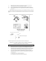
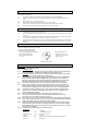
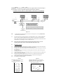
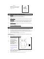
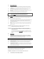
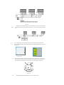
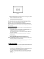
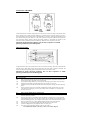
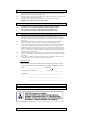
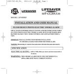
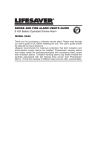
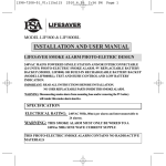
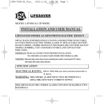
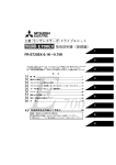
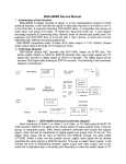
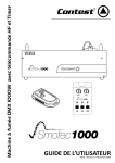
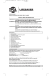
LIFESAVER
MODEL LIF 3000 SMOKE ALARM
LIF 3010 SMOKE ALARM
USER MANUAL
AUSTRALIAN ELECTRICAL
AUTHORITY CS: 96262V
IONISATION DESIGN
IMPORTANT: READ ALL INSTRUCTIONS BEFORE INSTALLATION.
NO USER REPLACEABLE PARTS INSIDE THIS SMOKE ALARM.
Do not attempt to repair the smoke alarm yourself.
RETURN TO SUPPLIER FOR REPAIRS.
SPECIFICATION
ELECTRICAL RATING: 240VAC 50Hz, 80mA per alarm, interconnectable up to 24 alarms.
WARNING: THIS SMOKE ALARM MUST ONLY BE WIRED TO A 240VAC 50Hz SINE
WAVE CURRENT SUPPLY.
The smoke alarm uses an extremely small amount of a radioactive element in the dual ionization chamber.
CONTENTS
1.
2.
3.
4.
5.
6.
7.
8.
9.
10.
11.
12.
13.
14.
15.
16.
17.
18.
RECOMMENDED LOCATIONS OF ALARMS AND REMOTE TEST & HUSH PLATE
MOBILE HOME INSTALLATION
AVOID THESE LOCATIONS
FALSE ALARMS
HOW TO REMOVE SMOKE ALARM FROM BASE PLATE
INSTALLATION
OPERATION, TESTING AND MAINTENANCE
BATTERY TEST
LIFESAVER MODEL LIF3010 WITH NC/NO RELAY
REPAIRS AND SERVICES
GOOD SAFETY HABITS
THE LIMITATIONS OF SMOKE ALARMS
OPERATING PRINCIPLES OF SMOKE ALARMS
DEVELOP AND PRACTICE A PLAN OF ESCAPE
WHAT TO DO WHEN THE ALARM SOUNDS
INSTALLER PLEASE NOTE
WARNING: INSULATION TEST
WARRANTY AND LIABILITY
1.
RECOMMENDED LOCATIONS OF ALARMS AND REMOTE TEST & HUSH PLATES
1.1
Locate at least one alarm for each separate sleeping area in the immediate vicinity of the bedrooms.
Try to protect the exit path as the bedrooms are usually farthest from an exit. If there is more than
one sleeping area exists, locate additional alarms in each sleeping area in the immediate vicinity of
bedrooms.
Locate at least one alarm to protect any stairway as stairways act like chimney for smoke and heat.
Locate at least one alarm on every floor level.
Locate an alarm in every room where a smoker sleeps as additional protection.
Locate an alarm in every room where electrical appliances are operated (i.e. portable heaters or
humidifiers) as additional protection.
Locate an alarm in every room where someone sleeps with the door closed as additional protection.
The closed door may prevent the alarm from waking the sleeper.
Smoke, heat and other combustion products rise to the ceiling and spread horizontally. Mounting
the alarm on the ceiling in the center of the room places it closest to all points in the room. Ceiling
mounting is preferred in ordinary residential construction.
For mobile home installation select location carefully to avoid thermal barrier that may form at the
ceiling. For more details see Mobile Home Installation (Section 2).
When mounting alarms on the ceiling locate it at a minimum of 300mm from the side wall and
600mm from any corner (see diagram).
When mounting alarms on a wall, locate it at a minimum of 300mm from the ceiling level but not
more than 600mm from the ceiling level and any corner (see diagram) NOTE: The performance of
smoke alarms mounted on walls is unpredictable, the wall mounting position is not recommended
when ceiling mounting can be implemented.
1.2
1.3
1.4
1.5
1.6
1.7
1.8
1.9
1.10
1.11
1.12
1.13
1.14
When mounting the alarm at the apex of a sloping ceiling it should be located a minimum of
500mm from the apex but should not exceed 1500mm. (see diagram).
Locate smoke alarm at both ends of a bedroom hallway if the hallway is more than 9m long.
May be located near kitchen area (not over cooking surface) because of HUSH ® Control feature.
We do not recommend installation in areas of high condensation such as bathrooms due to potential
for false alarms
When mounting the smoke alarm on the ceiling or wall, we recommend the installation of a remote test
& hush plate. The remote test & hush plate will allow the user convenient access to the TEST and HUSH
features. For easy operation, the recommended height for the remote test & hush plate is about 1.2m from the
ground.
INSTALLATION OF SMOKE ALARM AND REMOTE TEST & HUSH PLATE
Smoke alarm with remote test & hush card
CEILING
Remote test & hush plate
WALL
Connection diagram between smoke alarm and remote test & hush plate
IMPORTANT: INCORRECT ORIENTATION OF SMOKE ALARMS MAY
DECREASE OPERATIONAL EFFECTIVENESS
2.
MOBILE HOME INSTALLATION
2.1
Mobile homes built in the past five to seven years have been designed and insulated to be energy
efficient. Install smoke alarms as recommended (refer to RECOMMENDED LOCATIONS).
In mobile homes that are not well insulated compared to present standards, extreme heat or cold can
be transferred from the outside through poorly insulated walls and roof. This may create a thermal
barrier which can prevent smoke from reaching a smoke alarm mounted on the ceiling. In such
units, install smoke alarm on inside partition between 300mm and 600mm from the ceiling.
If you are not sure about the insulation in your mobile home, or if you notice the walls and ceilings
are either hot or cold, install alarm on an inside wall. For minimum protection, install one alarm
close to the bedrooms.
2.2
2.3
For additional protection, see SINGLE FLOOR PLAN.
We recommend that the smoke alarm be tested after each journey.
3.
AVOID THESE LOCATIONS
Do not locate your alarm in:
3.1
The garage - products of combustion are present when you start your automobile.
3.2
In front of forced air supply ducts used for heating and air conditioning and other high airflow
areas.
3.3
In the peak of an “A ” frame type of ceiling.
3.4
In areas where temperatures may fall below 5°C or rise above 45°C.
3.5
In dusty areas, dust particles may cause smoke alarm to false alarm or fail to alarm.
3.6
In very humid areas or near a bathroom, moisture can cause false alarms.
4.
FALSE ALARMS
4.1
This smoke alarm is designed to minimize false alarms. Smoking will not normally set off the alarm
unless smoke is blown directly into the alarm.
Combustion particles from cooking may set off the alarm if the alarm is located close to the cooking
surface.
Large quantities of combustion particles are generated from spills or broiling, an alarm with a Hush
Control device is preferable near a kitchen environment for this reason.
If the alarm does sound, check for a fire first. If a fire is discovered, escape quickly and call the Fire
Brigade. If no fire is present, check to see if one of the reasons listed in Section 3 may have caused
the alarm.
4.2
4.3
4.4
5.
HOW TO REMOVE SMOKE ALARM FROM BASE PLATE
5.1 Remove Tamper Locking Screw if installed.
5.2 Look for ‘SLIDE TO REMOVE ’.
5.3 Push firmly towards arrow until
smoke alarm unhinges from base plate
5.4 To re-install smoke alarm,
follow FIGURE2 procedure
2.1 to 2.3.
Slide Smoke alarm cover
in direction of arrow (as
shown on cover) to remove
from base plate
Tamper Locking Screw
6.
INSTALLATION
WARNING: THIS SMOKE ALARM MUST BE INSTALLED BY QUALIFIED (LICENSED)
6.1
6.1.1
6.1.2
6.1.3
6.1.4
6.1.5
6.1.6
6.1.7
6.1.8
6.1.9
6.1.10
6.1.11
6.1.12
6.1.13
ELECTRICIANS ONLY.
Wiring Instructions:
In the interest of safety, a licensed electrician, in accordance with the relevant requirements of
the SAA Wiring Rules - AS3000, must install this smoke alarm and all wiring.
WARNING: This alarm must be wired to a continuous 240VAC 50Hz Sine Wave circuit. Ensure
any switching device cannot inadvertently override the unit.
This Smoke alarm can only be interconnected with other SMOTEC 3786/1 or LIFESAVER
Models 3000, 3010, 3800, 3800R, and 4800R Smoke alarms; whether it be of Ionisation or
Photoelectric design, Heat Alarm model HA240 and Visual Signaling Device model SL240.
Interconnection with other brands may cause damage or result in a shock or fire risk
Due to EMC noise interference, up to a limit of 24 smoke alarms may be interconnected.
There are four terminals in the supply terminal block, marked A, SW, N and LOOP . It is
important that the alarm be wired correctly to ensure correct operation. Incorrect wiring to
the Smoke alarm will damage the unit and invalidate the warranty. See Wiring Diagrams.
A maximum of 250 meters (820 feet) of wire can be used in interconnecting smoke alarms.
All final sub-circuit conductors including the signal conductor must be a minimum size of
1mm² with 250V grade insulation.
Interconnected Smoke alarms must be connected to the same final sub-circuit.
Do not use any wire that could later be confused with the normal house wires for the
interconnect wire. For example, green/yellow earth wire.
Do not connect AC power wires to SW interconnect terminal. This will damage smoke alarms.
Do not connect the SW interconnect wire to any device, except the SW interconnect terminal of
another smoke alarm. Otherwise, smoke alarms will be damaged.
Smoke alarms should be interconnected only within the confines of a single-family living unit.
If smoke alarms are interconnected between different units, there may be excessive nuisance
alarms. Residents may not be aware that smoke alarms are being tested or that it is a nuisance
alarm caused by cooking, etc.
Terminals at back of mounting base are marked as follows:
MARKINGS
(YELLOW )
C
COMMON
(GREY)
NC
NORMALLY CLOSE
( LIGHT BLUE )
NO
NORMALLY OPEN
( RED )
A
ACTIVE
(WHITE)
SW
SWITCH WIRE (FOR INTERCONNECTION ONLY)
( BLUE )
N
NEUTRAL
(GREEN)
LOOP
LOOP
WARNING: Connecting the Switch Wire terminal to any supply conductor will result in damage to
the alarm, failure to operate or shock hazard and will void the warranty of the alarm.
EXAMPLE OF MULTIPLE ALARM WIRING / ISOLATION UNIT WIRING
Figure 6.1
Note:
For interconnection of smoke alarms to Fire Panel or Auxiliary devices, use only LIFESAVER
Isolation Relay Model RK10A/9.
6.2
This smoke alarm can be interconnected only with other SMOTEC 3786/1 or LIFESAVER Models
3000, 3010, 3800, 3800R and 4800R Smoke alarms; whether it be of Ionization or Photoelectric
design, Heat Alarm model HA240 and Visual Signaling Device model SL240. Interconnection with
other brands may cause damage or result in a shock or fire risk.
6.2.1
When interconnected, all Smoke alarms will sound upon activation. However, only the
originating Smoke alarm will have a latched Red LED (38/48 /30series only).
6.3
Mounting Instructions:
6.3.1
Separate smoke alarm from mounting base by sliding cover (in direction of arrow) with one hand on
the back of the mounting base and one hand sliding the Smoke alarm.
Unhinge Smoke alarm from mounting base by removing hinge from under retaining flap of mounting
base. (See Fig.1)
Re-hinge Smoke alarm onto mounting base ensuring hinge is held securely under retaining flap of
mounting base. (Fig.1).
Align and slide smoke alarm up onto mounting base (Fig 1 & 3) then slide in the reverse direction of
arrow to ensure proper connection.
Switch on power and check the green light on alarm cover. It should be lit when mains power is
switched on indicating that the smoke alarm is properly connected to the mounting base.
Secure Tamper Locking Pin (supplied) to smoke alarm.
Test alarm by pressing Test button.
6.3.2
6.3.3
6.3.4
6.3.5
6.3.6
6.3.7
Figure 1:
F1.1 Slide metal clip (A) to corner of
base plate tongue (B).
F1.2 Slide metal clip fully, as shown
in figure.
Figure 2:
F2.1 Place smoke alarm in line to base plate.
F2.2 Push smoke alarm, towards connector (A).
F2.3 Green AC Power Light will come on
when connected to mains
Figure 3:
WARNING: For wall mount, the connector
must be at the bottom. Ensure “Slide To
remove ” arrow on the cover is pointing
upwards (vertical).
7
7.1
7.1.1
7.1.2
7.1.3
7.1.3.1
7.1.3.2
7.1:4
7.1.4.1
7.2
OPERATION, TESTING AND MAINTENANCE
Operation
The smoke alarm is operational once all wires are properly connected, the smoke alarm is correctly
installed on the mounting base and the alarm has been tested.
There are two LED indicators. Each of them has a unique function:
Red LED
Stand-by condition: will flash once approximately every 40 seconds to indicate unit is functioning
properly.
Alarm condition: will latch on when unit goes into alarm, indicating that products of combustion
have been detected. The latched Red LED and pulsating alarm will continue until the air is cleared.
For interconnected units, the originating smoke alarm Red LED will be latched on. All other units
will sound but not latch. The Red Led will diminish within 5 minutes and automatically resets.
Green LED
AC Mains-ON Indicator: indicates that the unit is operating with AC power. If this LED goes out,
it indicates that the AC power is off.
False Alarm Hush® Control Feature:
Note: Dense smoke will override Hush® control feature and sound a continuous alarm.
7.2.1
7.2.2
7.2.3
7.2.4
7.2.5
This smoke alarm has the capability of being temporarily desensitized for approximately 2 minutes.
The smoke alarm is desensitized by pressing the “HUSH ” button on the smoke alarm cover.
After pressing the “HUSH” button, the alarm will silence immediately and “chirp ” every 40 seconds
for approximately 2 minutes to indicate the alarm is in the temporary desensitized condition.
The smoke alarm will automatically reactivate after approximately 2 minutes and sound the alarm if
particles of combustion are still present.
The “Hush ” feature may be used repeatedly until the air has cleared.
WARNING: Before using the alarm “HUSH ” feature, identify the source of smoke and be certain
that a safe conditions exist.
7.3
Battery Installation and Replacement
7.3.1
To replace battery, remove alarm
from mounting base (see section
6.2) and remove the battery from
compartment. Replace the old
battery with a fresh one.
USE ONLY BATTERIES AS
SPECIFIED IN THE LABEL .
USE ONLY THE
FOLLOWING 9-VOLT
ALKALINE BATTERIES FOR
REPLACEMENT:
7.3.2
7.3.3
EVEREADY/ENERGIZER 522
DURACELL MN1604, MX1604
These batteries can be purchased
at your local retail outlets and
supermarkets.
7.3.4
7.3.5
Caution: Use of different battery may have a detrimental effect on operation or may cause the
battery to explode resulting in injure or fire.
Fold Red Battery Lever down into compartment with fresh replacement battery. Otherwise smoke
alarm cannot be hinged closed.
Battery can only be inserted in one direction. Ensure polarity is correct.
7.4
Battery Replacement:
7.4.1
The smoke alarm uses one 9V battery to automatically provide back-up power to the alarm if
AC power fails. The battery will operate the alarm for approximately one to three months with
AC power off.
The smoke alarm has a low/missing battery indicator which will cause the unit to ‘chirp ’and
flash the Red LED at approximately 40 second intervals for a minimum of 7 days.
Replace battery when chirping occurs. To ensure proper operation, the battery should be replaced
once a year.
Replace battery with Eveready Alkaline 522 or Duracell MN1604 or MX1604.
Lay black ribbon in battery compartment for ease of future battery removal.
7.4.2
7.4.3
7.4.4
7.4.5
WARNING: Use of inferior batteries or incorrect types may cause a malfunction of the
alarm. When replacing battery and on connecting back the detector to the
base plate, make sure that the detector is fully connected and flush with
the base plate.
7.5
Testing:
Note: Before testing make sure that the smoke alarm is connected to AC power supply and there is a 9V
battery properly installed. Make sure the Green LED is ON.
7.5.1
7.5.2
7.5.3
7.5.4
Test alarm by pushing and holding the test button for a few seconds. This should sound the alarm if
all electronic circuitry and horn are working. Test alarm weekly to assure proper operation.
If no alarm sounds, check wiring, fuses or circuit breaker and make certain that alarm is connected
to a continuous final sub-circuit.
With interconnected units, activating the test button on one unit will cause all connected units to
sound.
Continuous chirping or erratic noise or low sound from an alarm may indicate a defective alarm.
Return it for service.
WARNING: Do not apply excessive force on the “TEST ” and “HUSH ” buttons, this may
damage the smoke alarm and may void the warranty.
WARNING: Never use an open flame of any kind to test your alarm. You may damage the
alarm or set fire to your home. The built in test switch enables testing of all electronic
components and the horn.
To accurately test the integrity of the sensing chamber use a smoke detector (aerosol)
®
tester. We recommend using the LIFESAVER LT711 Smoke Detector Tester for this
purpose.
7.6
Maintenance:
7.6.1
The smoke alarm is virtually maintenance free. However, under dusty or greasy conditions, a
vacuum cleaner may be used to clean the exterior of unit (including slots on cover). DO NOT
IMMERSE IN OR SPRAY WITH HOUSEHOLD CLEANERS. We recommend a periodic
monthly inspection of the smoke alarm to ensure that it is free of dirt.
8.
BATTERY TEST
8.1.0
8.1.1
We recommend a weekly battery test.
Switch off mains power OR unhinge the smoke alarm from its base plate. The Green LED on the
smoke alarm will be OFF.
Test alarm by pressing on the Test Button for a few seconds. This should sound the alarm.
Watch the Red LED for about 40 seconds. It should flash at least once. It the Red LED is ON, it
should diminish within 5 minutes.
After the battery test, return the alarm to normal operation. Switch on mains power OR hinge the
smoke alarm back onto its base plate only when smoke alarm passes the above tests. The Green
LED on the smoke alarm will come ON.
8.1.2
8.1.3
8.1.4
9.
LIFESAVER MODEL LIF3010 WITH NC/NO RELAY
If you have purchased and installed the LIF3010 smoke alarm with the NC/NO Relay, please note that the
operation and features of this model smoke alarm is the same as the LIF3000.
The LIF3010 smoke alarm has 7 terminals and they are colour coded.
WARNING: THIS TERMINAL IS NOT ISOLATED FROM THE MAINS SUPPLY
9.1
9.1.1
This seven terminal has a relay output (C, NC and NO):
A relay output may have a power loading (See figure 9.1).
Figure 9.1
9.1.2
WARNING: The loading power must be less than 5Ax250VAC/10Ax125VAC/10Ax30VDC
The smoke alarms can be interconnected to a maximum of twenty-four pieces.(please see figure
9.2)
Figure 9.2
9.1.3
9.1.4
Test if smoke alarm is okay by operating remote test & hush plate connected to smoke alarm.
LIFESAVER Model LIFTHC: CHIP FOR REMOTE TEST & HUSH OPERATION (see figure 9.3
and figure 9.4)
Figure 9.3 (top)
9.1.5
Figure 9.4 (bottom)
By inserting this LIFTHC chip into the smoke alarm as shown in the diagram, it will allow your
smoke alarm to be wired to the remote test and hush plate (LIFTHP). If your smoke alarms are
interconnected, you would require a LIFTHC chip for each smoke alarm. (see figure 9.5)
Figure 9.5
9.1.6
LIFESAVER MODEL LIFTHP: REMOTE TEST AND HUSH PLATE:
Figure 9.6
Note: By installing this LIFTHP remote test and hush plate on the wall, it will allow you to test and hush
your smoke alarm easily. The LIFTHP test and hush plate can be installed singly or if your smoke
alarms are interconnected, only one plate is required.
9.2
OPERATION OF REMOTE TEST & HUSH P ATE:
Define system units: A system may be connected maximum of 24 units, they are SMOTEC
3786/1, LIFESAVER models LIF3000, LIF3010, 3800, 3800R, 4800R, 4800RL, Heat alarm
model HA240, Visual Device model SL240 and Relay model RK10A/9.
Note: Before testing a system, make sure all wires and the Remote Test & Hush Plate
are connected to whole system units, LIF3000 series smoke alarms must have the
LIFTHC Cards installed. If they have no LIFTHC Cards, in testing the system, their red
LEDs will not light.
9.2.1 TEST button on LIFTHP
9.2.1.1 To Activate: PRESS and Release TEST button to sound all smoke alarm/s and
devices, the description as below:
• LIF3000 series smoke alarms with LIFTHC cards should always keep
sounding, their red LEDs will be latched on. Any LIF3000 series smoke alarm
without the LIFTHC Card, its red LED will not light.
Note: Please check for above 7 seconds, otherwise, maybe it indicates an
instability phenomenon.
• All the heat alarms & the other smoke alarms should sound. The red LED
should not light.
• SL240 should flash.
• RK10A/9 should be activated after approximately 10s.
Note: For more information please refer to each model manual.
9.2.1.2 To Cancel: PRESS and Release TEST button again to stop all smoke alarm/s
and devices sounding, the description as below:
• The LIF3000 or LIF3010 smoke alarms with LIFTHC card should stop sound,
at the same time the red LED will diminish within 5 minutes.
• SL240 should stop flash immediately
• RK10A/9 relay should reset to normal status.
9.2.2. HUSH button on LIFTHP
Note: The Remote Hush signal can be received by LIF3000 and LIF3010 Smoke Alarms
with LIFTHC only, And also only silence the LIF3000 and LIF3010 in sound state
caused by detect smoke or testing by pressing test button.
• To silence false and nuisance alarms, PRESS the HUSH button once.
• The smoke alarm/s will chirp for 2 minutes
• The smoke alarm/s will automatically reactivate after approximately 2 minutes
and sound the alarm if particles of combustion are still present.
•
The “Hush ” feature on the LIFTHP may be used repeatedly until the air has
cleared.
• The originating smoke alarm red LED will remain on and diminish within 5
minutes.
Please note:
If there is no alarm activation, pressing the HUSH button on the plate will not operate the Hush mode.
This means that the smoke alarm/s will not be desensitized and chirp.
WARNING:
Before using the “Hush ” feature on LIFTHP, identify the source of smoke and be certain that safe
conditions exist.
10.
REPAIRS AND SERVICES
10.1
10.2
The smoke alarm uses a very small amount of radioactive element which is safely contained within
the sealed source.
If the smoke alarm is defective in any way, do not tamper with the unit. Return the unit to
your supplier. (See warranty for instructions on in warranty returns.) There will be a service
charge for repairing units out of warranty.
10.3
For service, return to PSA Products Pty Ltd, 17 Millicent Street, Burwood, Victoria, 3125.
Note: NO USER REPLACEABLE PARTS INSIDE.
•
Please note: It is illegal to send radioactive material through Australia Post. Check for similar
conditions with any forwarding agency before sending this article.
WARNING: DO NOT TAMPER WITH RADIOACTIVE SOURCE
11.
GOOD SAFETY HABITS
The use of this product should not be seen as a substitute for basic safety precaution in the prevention of
FIRE.
There are situations where a smoke alarm may not be effective to protect against fire:
•
Smoking in bed
•
Leaving children home alone
•
Cleaning with flammable liquids, such as petrol.
12.
12.1
12.2
12.3
12.4
12.5
12.6
12.7
12.8
12.9
12.10
12.11
12.12
13.
THE LIMITATIONS OF SMOKE ALARMS
Smoke alarms are devices that can provide early warning of possible developing fires at reasonable
cost.
Alarms have sensing limitations. Ionization smoke detection technology may be more responsive to
invisible particles produced by most flaming fires.
Photoelectric smoke detection technology may be more responsive to visible particles produced by
most smoldering fires. Home fires develop in different ways and are often unpredictable. Neither
type of alarm (photo-electric/ionisation) is always best and a given alarm may not always provide
warning of a fire.
Smoke alarms have certain limitations. For battery powered smoke alarms, the battery must be in
good condition and installed properly.
AC powered alarms will not operate if AC power has been cut off, such as by an electrical fault,
open fuse or circuit breaker, or fire. However, the battery back-up will activate the alarm if in good
working order.
Smoke alarms must be tested regularly to ensure that the batteries and alarm circuit are in good
operating condition.
Smoke alarms cannot provide an alarm if smoke does not reach the alarm. Therefore, smoke alarm
may not sense fires starting in chimneys, walls, on roofs, on the other side of a closed door, or on a
different floor.
If the alarm is located outside the bedrooms, or on a different floor, it may not wake up a sound
sleeper. A smoke alarm in the bedroom, therefore, is recommended as additional protection.
Smoke alarms have been significant in saving lives in many parts of the world. However, U.S.
Government research indicates that they may not give early enough warning in up to 35% of fires.
Hence, the use of this product does not substitute for basic prevention and total protection.
Although smoke alarm can help save lives by providing early warnings of a fire, they are not a
substitute for an insurance policy.
This smoke alarm alone will not alert the hearing impaired. Use special purpose smoke alarm with
lights or vibrating devices, for those hard of hearing.
Heat alarms are available to offer greater security when used in conjunction with smoke alarms.
OPERATING PRINCIPLES OF SMOKE ALARMS
IONISATION CHAMBER
A man-made radio-active element, Americium 241 0.9 microcurie is used in this design. This element ionizes
the air around it and as a result, excellent conductivity is possible (refer to illustration showing ‘Clear Air’).
Current supplied by either the mains power (where applicable), or the battery would pass through the gap with
ease without causing any alarm. However, in the event of particles arising from combustion or dust particles
(refer illustration showing ‘Smoke’) entering the Sensing Chamber, it encapsulates the ionized air. This
interaction causes an increased resistance to conductivity. When this occurs, the alarm is activated.
Ionization smoke detection technology may be more responsive to invisible
particles produced by most flaming fires.
PHOTOELECTRIC
A light transmission source and a photosensitive receiver are used in this design. Light that is transmitted fall
upon the receiver. When smoke or dust enters the light path, some of the light is scattered or absorbed. The
result of a reduction of light falling upon the photosensitive receiver will cause an alarm.
Photoelectric smoke detection technology may be more responsive to visible
particles produced by most smoldering fires.
14.
DEVELOP AND PRACTICE A PLAN OF ESCAPE
Basic of escape plan
14.1
Make a floor plan indicating all doors and windows and at least two escape routes from each room.
Second storey windows may need a rope or chain ladder.
14.2
Have a family meeting and discuss your escape plan, showing everyone what to do in case of fire.
14.3
Determine a place outside your home where all of you can meet, if a fire occurs.
14.3
Familiarize everyone with the sound of the smoke alarm and practice leaving your home when they
hear it.
14.4
Practice a fire drill at least every six months, including drills at night. Practice allows you to test
your plan before an emergency. You may not be able to reach your children. It is important that
they know what to do!
15.
15.1
15.2
15.3
15.4
15.5
15.6
WHAT TO DO WHEN THE ALARM SOUNDS
Leave immediately by your plan of escape. Every second counts, so don’t waste time getting
dressed or picking up valuables.
In leaving, don’t open any inside door without first feeling its surface. If hot, or if you see smoke
seeping through cracks, don’t open that door! Instead, use your alternate exit. If inside door is cool,
place your shoulder against it, open it slightly and be ready to slam it shut if heat and smoke rush in.
Stay close to the floor if air is smoky. Breathe shallowly through a wet cloth if possible.
Once outside, go to your selected meeting place and make sure everyone is there.
Call the Fire Brigade from your neighbour’s home - not from yours!
Don’t return to your home until officials say that it is safe to do so.
For additional information on fire safety, contact your local Fire Brigade.
16.
16.1
16.2
16.3
16.4
17.
17.1
17.2
17.3
18.
18.1
18.2
18.3
18.4
18.5
INSTALLER PLEASE NOTE:
Before you connect the mains power, check wiring polarity.
If alarm ‘chirps ’ intermittently, this sound is due to the “HUSH ” button having been activated.
Allow approximately 10 minutes for the alarm to reset.
If the alarm ‘chirps ’ again, press the Test button to check the battery condition. If the Yellow LED
is flashing, the smoke alarm should be replaced.
If ‘chirps ’ persists, replace smoke alarm and return to your supplier for replacement.
NOTE: NO USER REPLACEABLE PARTS INSIDE.
WARNING: INSULATION TEST
UNDER NO CIRCUMSTANCES MUST AN INSULATION RESISTANCE TEST BE
CARRIED OUT ON A CIRCUIT TO WHICH A SMOKE ALARM IS FITTED.
THE TEST COULD CAUSE IRREPARABLE DAMAGE TO THE INTERNAL
CIRCUITRY OF THE SMOKE ALARM AND MAKE IT INOPERATIVE.
THE WARRANTY WOULD BE VOID UNDER SUCH CIRCUMSTANCES.
WARRANTY AND LIABILITY
PSA Products Pty Ltd warrants that for five years from the date of manufacture of the smoke alarm,
it will repair or replace the smoke alarm (at the option of PSA Products Pty Ltd) due to any
manufacturing defect, at the cost of PSA Products Pty Ltd (excluding any labour costs relating to
removal or re-installation of product, and transport costs). This warranty does not extend to the
battery if any.
This warranty shall not apply to the smoke alarm if it has been damaged, modified, abused or
altered after the date of purchase, or if it fails to operate due to improper maintenance.
To the extent permitted by law, the liability of PSA Products Pty Ltd arising from the sale of this
smoke alarm or under the terms of this limited warranty shall not in any case exceed the cost of
replacement of smoke alarm and subject to this clause. In no case shall PSA Products Pty Ltd be
liable for consequential loss or damages resulting from the failure of the smoke alarm or breach of
this, or: Any other warranty, express or implied, loss or damage caused by failure to abide by the
instructions supplied in the leaflets.
To the extent permitted by law, PSA Products Pty Ltd., makes no warranty, expressed or implied,
written or oral, including that of merchantability or fitness for any particular purpose, with respect
to the battery.
This warranty is an addition to and does not exclude the rights of consumers under the Australia
Trade Practices Act 1974, or any other law which may not be excluded.
Warranty Form
Please retain this warranty section and complete the details below. When you claim
warranty for the product. Please present this section together with the faulty product.
Model :_____________________________ Serial Number: _______________
Date Of Purchase/ Installation : ___________
Invoice No : _______________
Installed By: ______________________________________________________
_______________________________________________________
_______________________________________________________
This smoke alarm has a recommended service life of at least 10 years under normal conditions of use.
THIS SMOKE ALARM HAS BEEN TESTED AND PASSED TO AS3786-1993
Am 241
DEAR ELECTRICIAN:
PLEASE LEAVE THIS MANUAL FOR THE OWNER.
THANK YOU FOR CHOOSING THIS SMOKE ALARM.
Another Quality Product By:
PSA Products Pty Ltd
17 Millicent Street, Burwood, Victoria 3125
Ph:
(03) 9888 9889
Fax:
(03) 9888 9993
Email: [email protected]
Website: http://www.psaproducts.com.au
1298-7201-00