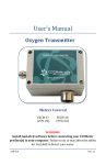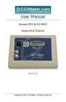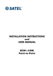
1
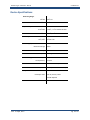
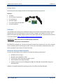
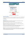
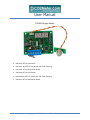
User Manual TR250Z Oxygen Sensor CM‐0134 25% O2 Transmitter CM‐0134‐ WT 25% O2 Transmitter with Tube Sampling CM‐0150 25% O2 with Mount Shield CM‐0160 95% O2 Transmitter CM‐0160‐WT 95% O2 Transmitter with Tube Sampling CM‐0161 95% O2 with Mount Shield Copyright © 2015 CO2 Meter. All Rights Reserved. TR250Z Oxygen Transmitter – Manual CO2Meter.com Table of Contents WELCOME ..................................................................................................... 3 IMPORTANT SAFEGUARDS ............................................................................ 3 DEVICE SPECIFICATIONS ................................................................................ 4 PACKAGE CONTENTS ..................................................................................... 5 SOFTWARE ................................................................................................ 5 MINIMUM SYSTEM REQUIREMENTS ............................................................... 5 QUICK START GUIDE ................................................................................... 6 DESCRIPTION ............................................................................................. 6 STANDARD OPERATION ................................................................................. 7 ENTERING THE SERVICE MENU ...................................................................... 7 PERFORMING AN ATMOSPHERIC SPAN CALIBRATION .................................... 7 PERFORMING A 0% OXYGEN ZERO POINT CALIBRATION ................................ 8 TERMINAL CONNECTORS ............................................................................... 8 0‐10V OUTPUT (OPTIONAL) ........................................................................... 8 MODBUS / RS‐485 ......................................................................................... 9 INPUT REGISTERS ........................................................................................ 9 HOLDING REGISTERS ................................................................................... 9 POWERING THE UNIT................................................................................... 9 LCD DISPLAY ............................................................................................. 9 THEORY OF OPERATION ............................................................................. 10 CALIBRATION ........................................................................................... 10 CALIBRATING USING MODBUS OR PC CONNECTION ...................................... 10 SUPPORT ..................................................................................................... 12 WARRANTY ................................................................................................. 12 RETURNS ..................................................................................................... 12 LIABILITY ..................................................................................................... 13 CONTACT US ............................................................................................... 13 Rev. 27 April, 2015 Pg. 2 of 13 TR250Z Oxygen Transmitter – Manual CO2Meter.com Welcome Thank you for purchasing the TR250Z Oxygen Sensor. The TR250Z is a long life 25% or 95% oxygen level transmitter that provides multiple analog linear outputs of O2 concentrations. It’s designed to be a rugged, maintenance‐free add‐on for OEMs or can be used as a desktop device. In addition, it can be calibrated in normal air, or can use a calibration gas of any known oxygen concentration. Our goal is to make high‐quality, low‐cost gas detection and indoor air quality products available to you. Please take some time to read through this manual in order to get the most out of your meter. Make sure to visit our website regularly to find more information about this product and to download the software free. Once you download and install the software, you can use the “Check for updates” function under the Help menu to search for new updates. Please also pay special attention to the important safeguards shown on the pages ahead. Important Safeguards To reduce the risk of fire, electrical shock and/or injury to persons, basic safety precautions should always be followed when using electrical appliances, including the following: 1. READ ALL INSTRUCTIONS BEFORE USING THIS DEVICE! 2. Use only the supplied power supply to operate the unit. 3. Ensure that when sampling in a closed environment that the tubes are securely fashioned to the device. 4. Do not operate with a blocked off sample path. 5. Do not operate the device if it is malfunctioning. 6. Do not install the device outside in exposed conditions. Due to the nature of the design the enclosure cannot be made water‐tight and the unit must not be exposed to water. 7. Do not operate the device with the cover detached. SAVE THESE INSTRUCTIONS! Rev. 27 April, 2015 Pg. 3 of 13 TR250Z Oxygen Transmitter – Manual CO2Meter.com Device Specifications Measuring Range: 25% O2 0‐25% vol. 95% O2 0‐95% vol. Repeatability: 0‐25% CO2 ± 0.05%, ± 1 % of measured value 0‐95% O2 ± 0.02%, ± 1 % of measured value Accuracy 25% / 95% ±2% full scale Power Supply: Maximum Voltage 24VDC Minimum Voltage 20VDC Power Consumption 600mA @ 24VDC Sensor Ratings: Life Expectancy Maintenance Interval Warm‐up Time >15 years No maintenance required <15 min (instant measurements) Outputs: O2 Output Value 4‐20 mA, linearly scaled 2‐10VDC Optional RS‐485 Rev. 27 April, 2015 Modbus Interface Pg. 4 of 13 TR250Z Oxygen Transmitter – Manual CO2Meter.com Package Contents Please verify that your package contains the following items before using the unit: Contents: (1) Meter (1) Certificate of Calibration (1) User Manual (1) Power supply (1) 2 Meter USB to RS‐485 Cable (1) Screen Breather Software Visit CO2Meter.com and go to the “Downloads” page (see link below) to download our DAS or GasLab software free or for more information on how to connect, configure, and calibrate your meter. For general information about the program, please see the DAS or Gas‐Lab User Instruction Manual located in the website below. http://www.co2meter.com/pages/downloads IMPORTANT: MAKE SURE TO INSTALL SOFTWARE BEFORE CONNECTING YOUR DEVICE TO YOUR COMPUTER By installing our software first, you will ensure that the proper driver necessary for your unit is installed on your computer before connecting your meter. Click on the “Install Now” link and then select “Run” when prompted by your browser (as shown on below). Minimum System Requirements To utilize our free software, your computer must meet the following requirements: Windows XP SP3 or higher Microsoft .Net Framework 3.5 SP1 Pentium 4 (or newer) operating at 2.4Ghz or faster 1GB of Random Access Memory (RAM) Hard disk space with at least 20 Megabytes (MB) free (200+MB recommended for logs and application files) Software is compatible with 64‐bit operating systems and is fully tested with Windows. Rev. 27 April, 2015 Pg. 5 of 13 TR250Z Oxygen Transmitter – Manual CO2Meter.com Install DAS online (Internet Explorer 9 shown) Quick Start Guide Make sure you read through these instructions thoroughly before using your meter. This guide will help you familiarize with your meter in order to be as productive as you need to be in the least amount of time possible. Description Display – Main interface to view current sensor readings and menu state. Will blink “STRT” upon applying power while the sensor warms up and stabilizes. LEDs – are in for lower right corner of the unit on the main PCB and are labeled S, E and P. S LED – Status LED. Blinks every time a complete measurement cycle is performed and the value is updated. Serve’s as a heartbeat for transmitter operation. E LED – Error LED. Will light if any abnormal conditions are detected within the device, primarily the sensor falling out of its recommended operating specifications will trigger this lamp. P LED – Power LED. Will be on continuously when power is applied to the unit. Buttons ‐ The unit has three surface mount buttons above the LEDs on the PCB. They can be gently and carefully pressed with your finger. These buttons allow you to access all aspects of sensors operation and test or calibrate different functional modules. Rev. 27 April, 2015 Pg. 6 of 13 TR250Z Oxygen Transmitter – Manual CO2Meter.com Standard Operation The O2 transmitters comes factory calibrated for easy installation. During its life cycle calibration may become periodically necessary. We recommend performing a span O2 calibration every month for guaranteed operation and ensured accuracy. No other calibration is necessary during the life cycle of the sensor. Entering the Service Menu To enter the service menu the buttons must be pressed in a factory‐set order. This code can be customized before shipment but by default will be 1‐2‐3. The buttons must be pressed within a half second of each other, else the unit will return to standard operating mode. When in the service menu the unit will not update the current O2 readings. Once you enter the menu the display will read “1234” or “2222”. Performing an Atmospheric Span Calibration 1. 2. 3. 4. 5. 6. 7. Allow sensor to stabilize for at least 1 hour Ensure the sensor is exposed to fresh air Enter the service menu when you press 123 one after another in that sequentially. The display will show 1234 flashing indicating that you are in the service menu Press 2 to enter the Oxygen submenu Press 2 again to perform the atmospheric calibration Press 3 to escape Rev. 27 April, 2015 Pg. 7 of 13 TR250Z Oxygen Transmitter – Manual CO2Meter.com Performing a 0% Oxygen Zero Point Calibration 1. 2. 3. 4. 5. 6. 7. 8. 9. Allow sensor to stabilize for at least 1 hour Screw on the calibration adapter Apply N2 calibration gas Wait 5 minutes for stable readings Enter the service menu when you press 123 one after another in that sequentially. The display will show 1234 flashing indicating that you are in the service menu Press 2 to enter the Oxygen submenu Press 1 to calibrate Press 3 to escape Terminal Connectors 1. 2. 3. 4. VDC = G‐ G+ O2 4‐20mA = SIG GND RS‐485 INTERFACE = A B GND RESET = RST 0-10V Output (Optional) To get a 10 volt span (2‐10 volt in practice) from a 4‐20 mA line, add a 500 ohm resistor from signal to ground. 500 ohms x .004 amps = 2 volts and 500 ohms x .020 amps = 10 volts. Install the resistor at the receiving end, as this eliminates all voltage drops from resistance in the wire. 4‐20mA and 2‐10V are used so it can be determined if the transmitter is actually present. Less than 4mA or 2V: no transmitter, not connected or no signal. Rev. 27 April, 2015 Pg. 8 of 13 TR250Z Oxygen Transmitter – Manual CO2Meter.com Modbus / RS-485 The sensor support MODBUS protocols over RS‐485, unidirectional transmission at 9600kbps. Address 0 or FE. The following Modbus registers are available: Input Registers 1. O2 Value, x10 2. Raw ADC Value Holding Registers 1. 2. 3. 4. 5. 6. 7. 8. O2 Span Value (4 byte floating number, part 1) O2 Span Value (4 byte floating number, part 2) O2 Pot Value 4‐20mA output Zero Value 4‐20mA output Span Value (4 byte floating number, part 1) 4‐20mA output Span Value (4 byte floating number, part 2) Control Register Status Register The following commands are available: 0x03 – Read Holding Register 0x04 – Read Input Register 0x06 – Write Holding Register Powering the Unit The unit can be powered by hardwiring 24 VDC power through the MDCM‐4FP‐2M Cable (included) but sampling units can also be powered by the included 24VDC International wall power supply. LCD Display The Liquid Crystal Display (LCD) screen shows the following features: CO2 in percentage format (##.##%) for 100% Rev. 27 April, 2015 Pg. 9 of 13 TR250Z Oxygen Transmitter – Manual CO2Meter.com Theory of Operation The zirconia oxygen sensor utilizes solid‐state electrochemical reactions to produce a voltage proportional to the current oxygen. This voltage is then digitalized and filtered to a usable value. The oxygen sensor has also been factory calibrated to meet specifications. Calibration The calibration process varies depending on the type of unit and whether it has optional data logging functionality or not. All units are factory‐calibrated with multiple reference points of gas, and have been verified to be accurate within their specific functionality before shipment. However, if the unit is severely jolted or otherwise mechanically disturbed, the sensor can drift requiring recalibration. All calibration procedures follow a single‐point calibration routine that effectively shifts the zero‐point of the O2 sensor. Calibrating using MODBUS or PC Connection You can Download the software directly and free from this link in our website. (http://www.co2meter.com/pages/downloads) More precise calibrations can be performed using the PC connection. The unit can be attached to a PC using an optional USB to RS‐485 cable, available on our website, or via a mini‐USB cable to the internal USB connection. Calibration of the Oxygen Sensor In the desktop software application O2 can be calibrated individually. The O2 sensor can be calibrated to 0% and then to 20.9%. During normal operation 0% calibration of the oxygen transmitter should not be necessary. Calibration can also be performed over MODBUS, see additional documentation for MODBUS registers. Rev. 27 April, 2015 Pg. 10 of 13 TR250Z Oxygen Transmitter – Manual CO2Meter.com Calibration can be performed using either 0% CO2 calibration gas (typically nitrogen, Argon, etc.), or using a fresh source of air, assumed to be approximately 20.9% O2. Attach calibration gas to the unit and connect the unit to a personal computer. Open the calibration screen in the DAS software. Click the “Calibrate” button in the calibration tab for the desired gas, located in the “Configure Sensor” screen. As long as the gas concentration is stable, the unit should instantly reflect the calibrated value. This can be confirmed by watching the display. To see the calibration value in real time, click in the “Collect Real time” button to capture these values before opening the configuration screen. Real‐time capture Zero or Fresh Air Calibration Apply gas and select the appropriate concentration and Click the “Calibrate” button. The sensor reading should instantly reflect the calibration. NOTE: DO NOT ADJUST THE SPAN VALUE. Rev. 27 April, 2015 Pg. 11 of 13 TR250Z Oxygen Transmitter – Manual CO2Meter.com Support The quickest way to obtain technical support is via email. Please send all support enquires to [email protected]. In your email, please include a clear, concise definition of the problem and any relevant troubleshooting information or steps taken so far, so we can duplicate the problem and quickly respond to your inquiry. Warranty This unit comes with a 1YEAR (warranty period) limited manufacturer’s warranty, starting from the date the unit was shipped to the buyer. During this period of time, CO2Meter.com warrants our products to be free from defects in materials and workmanship when used for their intended purpose and agrees to fix or replace (at our discretion) any part or product that fails under normal use. To take advantage of this warranty, the product must be returned to CO2Meter.com at your expense. If, after examination, we determine the product is defective, we will repair or replace it at no additional cost to you. This warranty does not cover any products that have been subjected to misuse, neglect, accident, modifications or repairs by you or by a third party. No employee or reseller of CO2Meter.com’s products may alter this warranty verbally or in writing. Returns If the product fails under normal use during the warranty period, an RMA (Return Material Authorization) number must be obtained from CO2Meter.com. After the item is received, CO2Meter.com will repair or replace the item at our discretion. To obtain an RMA number, please call CO2Meter.com at (877) 678‐4259. When requesting an RMA number, please provide the reason for return and original order number. If we determine that the product failed due to improper use (water damage, dropping, tampering, electrical damage etc.) or abuse, or if it is beyond the warranty period, we will inform you of the cost to fix or replace your device. If you are returning your device due to a warranty claim (with an RMA number) and you still have the unit original package, please use it to ship your unit to us. Please make sure to include the provided RMA number on the outside of the box, preferably on the shipping label. Make sure you secure the unit inside the package properly to prevent any damage during transit that could void your device’s warranty. Finally, please ship your device to the address shown under the “Contact Us” section below. CO2Meter.com will not, under any circumstances, be responsible for your shipment expenses and no refund will be issued for shipping charges necessary for you to ship the unit to us. Rev. 27 April, 2015 Pg. 12 of 13 TR250Z Oxygen Transmitter – Manual CO2Meter.com Liability All liabilities under this agreement shall be limited to the actual cost of the product paid to CO2Meter.com. In no event shall CO2Meter.com be liable for any incidental or consequential damages, lost profits, loss of time, lost sales or loss or damage to data, injury to person or personal property or any other indirect damages as the result of use of our products. Contact Us We are here to help! If the troubleshooting guide above doesn’t help you solving your problem or for more information, please contact us using the information below. [email protected] (877) 678‐4259 Toll free (M‐F 9:00am–6:00pm EST) (866) 422‐2356 www.co2meter.com Address: CO2Meter 131 Business Center Building A, Unit 3 Ormond Beach, FL 32174 Rev. 27 April, 2015 Pg. 13 of 13