1
novaPro32 Configuration
novaPro32 Configuration
User's Manual
7000904003 Q2
This description corresponds to the current
program release, Version 5.0. Changes may
occur at any time without prior notification.
7000904003 Q2
Sauter Systems
1
novaPro32 Configuration
2
7000904003 Q2
Sauter Systems
novaPro32 Configuration
0
Table of contents
1 Introduction...............................................................................................................9
1.1
1.2
The documentation for novaPro32...................................................................10
Configuration ...................................................................................................11
2 Password generation .............................................................................................13
2.1 Create a new user ...........................................................................................15
2.2 Change an existing user profile .......................................................................15
2.3 Password properties........................................................................................16
2.3.1 General information..................................................................................16
2.3.2 Task .........................................................................................................18
2.3.3 Picture/list ................................................................................................19
2.3.4 HDB/Trend ...............................................................................................21
2.3.5 Time programme......................................................................................22
2.3.6 Alarm list ..................................................................................................23
2.3.7 Calendar ..................................................................................................24
2.4 Default settings................................................................................................24
3 Filters.......................................................................................................................25
3.1 What are filters? ..............................................................................................25
3.2 Filters in novaPro32.........................................................................................26
3.3 Editing filters....................................................................................................27
3.3.1 Address filter configuration .......................................................................27
3.3.1.1 Example............................................................................................30
3.3.2 AS supervisor filter configuration ..............................................................31
3.3.3 AS group filter configuration .....................................................................32
3.3.4 Filter assistant ..........................................................................................33
4 Address groups ......................................................................................................35
4.1 Structure of an address group .........................................................................35
4.1.1 Structure using filters................................................................................35
4.1.2 Structure by individual address selection..................................................37
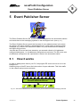
5 Event Publisher Server ..........................................................................................39
5.1 How it works ....................................................................................................39
5.2 Configuring the EP server................................................................................40
5.2.1 Create a new Event Publisher filter ..........................................................41
5.2.2 Edit an Event Publisher filter ....................................................................42
5.2.3 Show addresses of the Event Publisher server ........................................43
6 Alarm list .................................................................................................................45
6.1 Configuration ...................................................................................................46
6.1.1 Select user profile.....................................................................................46
6.1.2 Specifying the alarm list presentation .......................................................47
6.1.2.1 Modify an existing window template ..................................................48
7000904003 Q2
Sauter Systems
3
novaPro32 Configuration
0
Table of contents
6.1.2.2 Modify an existing window template.................................................. 49
6.1.3 Define a print template ............................................................................. 49
6.1.3.1 Create a new print template.............................................................. 49
6.1.3.2 Modify an existing print template....................................................... 50
6.1.4 Specify an address group ........................................................................ 50
6.1.5 Acoustic signal ......................................................................................... 52
7 Messaging...............................................................................................................53
7.1 Configuration................................................................................................... 54
7.1.1 The ‘Output Device Assignment’ tab ........................................................ 54
7.1.2 The ‘Output Device’ tab............................................................................ 56
7.1.2.1 Line printer........................................................................................ 57
7.1.2.1.1 Introduction .................................................................................57
7.1.2.1.2 Specific settings ......................................................................... 57
7.1.2.1.3 Defining an online printer............................................................. 58
7.1.2.2 E-mail and fax................................................................................... 61
7.1.2.3 Files.................................................................................................. 61
7.1.3 The ‘Output Layout’ tab............................................................................ 62
7.1.4 EP time programme ................................................................................. 64
7.1.4.1 Creating and configuring an EP time programme.............................. 64
7.1.4.1.1 Edit.............................................................................................. 65
7.1.4.1.2 New command ............................................................................ 65
7.1.4.1.3 Comment .................................................................................... 66
7.2 novaPro32/Micromedia Alert ........................................................................... 69
7.2.1 Configuration of novaPro32...................................................................... 69
7.2.1.1 Main function .................................................................................... 69
Setting up the EPP file:.................................................................................. 69
7.2.1.2 Full functionality ................................................................................ 72
Setting up the EPP files:................................................................................72
7.2.2 Configuration of Micromedia Alert ............................................................ 75
7.2.2.1 Install the Micromedia Alert program................................................. 75
7.2.2.1.1 Select Installation options............................................................ 76
7.2.2.2 Configuring the communication for Alert ........................................... 77
7.2.2.3 "Drivers" tab...................................................................................... 77
7.2.2.4 On-call management ........................................................................ 77
7.2.2.5 Message processor .......................................................................... 79
7.2.2.5.1 Activate the Message Processor ................................................. 79
7.2.2.5.2 Activate Interface......................................................................... 79
7.2.2.5.3 "Translations" tab ........................................................................ 80
7.2.2.5.4 "Alarms" tab ................................................................................ 80
8 Historical database ................................................................................................ 81
8.1
4
Configuration................................................................................................... 82
7000904003 Q2
Sauter Systems
novaPro32 Configuration
0
Table of contents
8.1.1 Add a new address group.........................................................................82
8.1.2 Edit an existing address group .................................................................83
8.2 HDB files .........................................................................................................84
8.2.1 Structure of the file designation ................................................................84
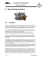
9 Dynamising pictures ..............................................................................................87
9.1 Pictures ...........................................................................................................87
9.1.1 The background picture............................................................................88
9.1.2 Create new picture ...................................................................................89
9.1.3 Import Windows Metafile (*.wmf) ..............................................................90
9.1.4 Change background picture .....................................................................91
9.1.5 Copy pictures ...........................................................................................91
9.1.6 Rename pictures ......................................................................................91
9.1.7 Delete pictures .........................................................................................92
9.1.8 Move pictures...........................................................................................92
9.1.9 Export pictures .........................................................................................92
9.1.10 Import pictures .........................................................................................92
9.2 How to edit dynamic points..............................................................................93
9.2.1 Display mode ...........................................................................................93
9.2.2 Editing mode ............................................................................................93
9.2.3 Default dynamisation (standard)...............................................................93
9.2.4 Own dynamisations ..................................................................................95
9.2.5 The right-hand toolbar ..............................................................................95
9.2.6 Selecting addresses ...............................................................................105
9.2.7 Using ‘drag and drop’ to select an address.............................................105
9.2.8 Positioning dynamic objects ...................................................................106
9.3 Start picture ...................................................................................................107
9.4 AS group pictures ..........................................................................................107
9.4.1 Create a new AS group picture...............................................................108
9.4.2 Dynamise AS group picture....................................................................109
10 Address list ...........................................................................................................111
10.1 Configuration .................................................................................................112
11 Time synchronisation...........................................................................................115
12 Page printers.........................................................................................................117
12.1 Introduction....................................................................................................117
12.2 How to configure a page printer.....................................................................117
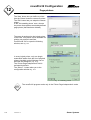
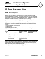
13 Copy Shareable_Data...........................................................................................121
13.1 Description ....................................................................................................121
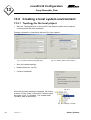
13.2 Creating a local system environment .............................................................122
13.2.1 Topology for the local project .................................................................122
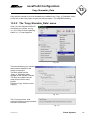
13.2.2 The ‘Copy Sharable_Data’ menu............................................................123
7000904003 Q2
Sauter Systems
5
novaPro32 Configuration
0
Table of contents
13.2.2.1 Description of the functions in the ‘Select files’ zone....................... 124
13.2.2.1.1 FBD files only ............................................................................124
13.2.2.1.2 Including logbook files ............................................................... 124
13.2.2.2 FBD and novaPro32 files ................................................................ 124
13.2.2.2.1 Including logbook files ............................................................... 125
13.2.2.2.2 Including document file.............................................................. 125
13.2.2.2.3 Including AS time-programme files............................................ 125
13.2.3 Starting the local project.........................................................................126
14 Document master .................................................................................................129
15 Logbook ................................................................................................................131
15.1 Logbook files .................................................................................................131
15.2 Analysing ......................................................................................................132
16 Help and online manuals .....................................................................................135
16.1 Using online help with novaPro32 ................................................................. 135
16.2 Read the manual on screen ..........................................................................135
16.3 Printing the manual .......................................................................................136
17 Index...................................................................................................................... 137
6
7000904003 Q2
Sauter Systems
novaPro32 Configuration
0
Table of contents
List of icons and symbols
Keyboard operation
Wait
diskette
Mouse operation
Single mouse click with left button
Single mouse click with right button
Double click with left button
Double click with right button
Description
Application
Information
Attention
Note
7000904003 Q2
Sauter Systems
7
novaPro32 Configuration
0
Table of contents
Trademarks
Designer
Micrografx Designer
Media Manager
Windows
Microsoft Office 97 Professional
MS Office
Microsoft Access 97
Microsoft Office 2000
Microsoft Word
Acrobat Reader
Pentium
8
7000904003 Q2
Trademark of Micrografx, Inc.
Trademark of Micrografx, Inc.
Trademark of Micrografx, Inc.
Trademark of Microsoft Corporation
Trademark of Microsoft Corporation
Trademark of Microsoft Corporation
Trademark of Microsoft Corporation
Trademark of Microsoft Corporation
Trademark of Microsoft Corporation
Adobe Systems Incorporated
Trademark of Intel Corporation
Sauter Systems
novaPro32 Configuration
1
Introduction
1 Introduction
novaPro32 comprises the management level of the EY3600 building management
system. This system is extremely user-friendly because it is built up consistently on the
basis of the Microsoft Windows operating system. The system's standard interfaces and
network capability make it possible to integrate building automation into the world of
office automation.
The configuration of novaPro32 is entirely menu-prompted, so there is no need for
specialised knowledge of computers or advanced language skills.
Users of the novaPro32 management system will find a detailed description of the
configuration on the following pages. These instructions offer a detailed explanation of
the configuration/parameterisation, but they deliberately do not cover the installation and
commissioning or the interaction with hardware components. This manual is therefore
intended quite specifically for maintenance and design engineering staff.
7000904003 Q2
Sauter Systems
9
novaPro32 Configuration
1
Introduction
1.1
The documentation for novaPro32
The operating instructions for novaPro32 are in three parts. Each part is intended for a
quite specific user group.
Part 1
User
Manual
Benutzerhandbuch
Part 2
Part 3
Configuration
Installation
Commissioning
!
! !
PD
!
PD
PD
T
1
Rev.
PD
PD
T
1
T
Rev.
A
B
AB
Operating staff
Doc. no. 7 000894 003
1) Introduction
2) Getting started
Starting novaPro32
3) Security Login, Logout
4) Alarm list
display, operation
5) The novaPro32 browser
6) Pictures
displays, operation
7) Protocols
8) Time profile
9) Calendar
10) Historical database
(HDB)/Trend
11) PC time programmes
12) Address list
13) Remote-island mode
14) Help, online
documentation
10
7000904003 Q2
Installation design
engineering
Commissioning staff
Doc. no. 7 000915 003
Maintenance staff
Installation design
engineering
Doc. no. 7 000904 003
1) General
2) Generating passwords
3) Filters
4) Address groups
5) Event publisher server
6) Alarm list
7) Online messaging
8) Historic database
9) Dynamising pictures
10) Address list
11) Synchronisation - AS
network
12) Printer
13) Copy Shareable_Data
14) Document master
15) Log book
16) Help & online
documentation
1)
2)
3)
4)
5)
6)
7)
8)
Introduction
Hardware, software
Installation
The novaPro32
project
Equipment table
Networks
Icon Maker
Glossary
Sauter Systems
novaPro32 Configuration
1
Introduction
1.2
Configuration
This manual describes the configuration of novaPro32, and is quite specifically intended
for the maintenance staff of an installation operator, and for the design engineers.
novaPro32 is configured using the ‘File | Configuration’ menu. Access to the separate
functions of this menu is solely reserved for authorised individuals.1
Function
Fig. 1-1: The ‘Configuration’ menu
See
page
EP system group
39
Alarm list
45
Online messaging
53
Password generation
13
Time synchronisation
115
HDB Server
81
Calendar
242
Address list
111
Printer
117
Copy Sharable_Data
121
PC Master
129
2 Password generation
2 See User manuel EY3600 novaPro32 nr. 7 000 894 003
7000904003 Q2
Sauter Systems
11
novaPro32 Configuration
1
12
Introduction
7000904003 Q2
Sauter Systems
novaPro32 Configuration
2
Password generation
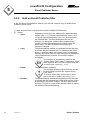
2 Password generation
novaPro32's functions are only accessible to authorised staff. A user identifies himself
in the system with a user name and a password. The user name and the password are
used as individual electronic codes or ‘keys’.
The code word/password can be used to assign rights to users on an individual basis.
Actions performed by the user are logged with his user name, making it possible to trace
interventions in the system.
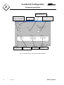
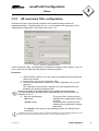
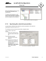
Use the ‘File | Configuration | Password generation’ menu to go to the overview
window. Global settings (i.e. settings that are valid for all users) are handled in the
‘Generate novaPro32 password’ overview window.
If the password function is switched off, all users will obtain unrestricted access to all the
functions in novaPro32.
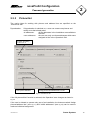
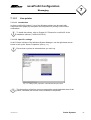
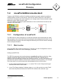
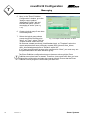
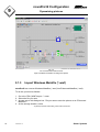
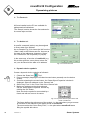
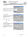
The ‘Password generation novaPro32’ overview window (see Fig. 2-1: ) contains a list of
all the users registered in the system. It also shows which users are currently logged
into the system (i.e. which ones are active), and when a user last logged in or out.
Only users with the ‘Supervisor‘ or ‘Password generation‘ authorisation can
assign rights to other users, delete rights, set up or delete new users, or
suspend/release users who are already registered.
Use the right-hand mouse button to go to the context menu for the overview window
(see Fig. 2-2: ). From here, you can set up new user profiles and you can also modify or
delete user profiles that already exist.
7000904003 Q2
Sauter Systems
13
novaPro32 Configuration
2
Password generation
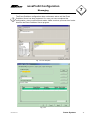
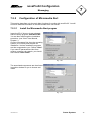
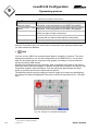
Switch Pre-login and Postlogin messages on or off.
Timeout: After the time
adjusted an automatic logout
appears and the novaPro32
workstation will be locked
User Status:
*: user logged in, now
X: suspended user
Switch the password on or off.
User List:
All users registered
Time and date
of the last login.
If selected, access to
novaPro32 will be denied
for 10 minutes after 3
invalid password entries.
Time and date of the
last logout.
Fig. 2-1: Overview window: ‘Password generation novaPro32’
14
7000904003 Q2
Sauter Systems
novaPro32 Configuration
2
Password generation
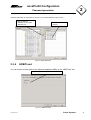
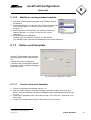
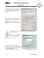
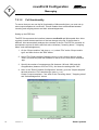
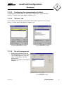
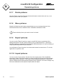
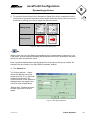
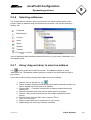
Open the user profile selected.
Create a new user profile.
Release a suspended user profile.
Suspend the user selected.
Delete the user selected.
Copy the user profile selected to the
clipboard.
Paste a profile from the clipboard.
Fig. 2-2: Context menu: ‘Password generation’
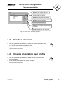
2.1
•
•
Use the right-hand mouse button to call up the context menu and select
the ‘New’ command.
You will see the ‘Password properties’ tabs.
Specify the user profile with the help of the ‘Password properties’ tabs
(see 2.3 Password properties)
2.2
•
•
•
Create a new user
Change an existing user profile
Use the right-hand mouse button to select the user you want in the
overview window.
In the context menu, select the ‘Open’ command.
Specify the user profile with the help of the ‘Password properties’ tabs.
(see 2.3 Password properties)
7000904003 Q2
Sauter Systems
15
novaPro32 Configuration
2
Password generation
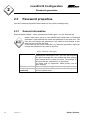
2.3
Password properties
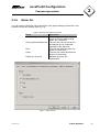
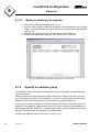
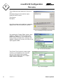
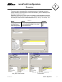
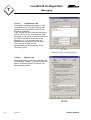
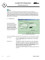
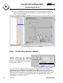
Use the ‘Password properties’ tabs to define a user profile unambiguously.
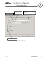
2.3.1
General information
Enter the basic settings – name, password and basic rights – on the ‘General’ tab.
When a new user is set up, a user with the basic ‘Supervisor‘ or ‘Password
generation’ rights specifies the name and password for the new user. The
new user can change the password to one which is more familiar to him
when he logs in for the first time.
A user who has the basic ‘Supervisor’ or ‘Password generation’ rights can
change the password of any user at any time.
Table 1: Password – basic rights
Supervisor
Print
Shut down
novaPro32
16
7000904003 Q2
The user is given all rights. He can use and
parameterise novaPro32 in full. The user also acquires
the right to manage the user profiles that have already
been created and to create new ones. The settings on
the other tabs are irrelevant for a ‘Supervisor’.
The basic right of ‘Supervisor’ takes priority over all
other settings.
The user is given the right to print.
Only users with the ‘Shut down novaPro32’ right can
shut the system down.
Sauter Systems
novaPro32 Configuration
2
Password generation
Passwort:
It is shown covered
Username
User AS code:
It identifies the user in the automation
station (AS)
Basic user rights
Fig. 2-3: ‘General’ tab
7000904003 Q2
Sauter Systems
17
novaPro32 Configuration
2
Password generation
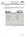
2.3.2
Task
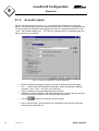
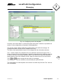
The ‘Task’ tab is used to release sub-programs of novaPro32 for the user. The buttons
on this tab should be regarded as main switches for the functions in question, i.e. subprograms can easily be switched off and on without changing the detailed parameters
on the subsequent tabs.
Visualisation and
editing tasks
Visualisation tasks
Fig.2-4: ‘Task’ tab
18
7000904003 Q2
Sauter Systems
novaPro32 Configuration
2
Password generation
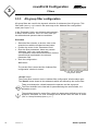
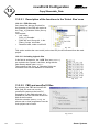
2.3.3
Picture/list
The user's rights for working with pictures and address lists are specified on the
‘Picture/List’ tab.
Dynamisation:
If dynamisation is switched on, a user can create new pictures and
modify ones that already exist.
all addresses:
all the addresses in the installation are available to
the user.
user addresses:
the user can only use those addresses which were
assigned to him in the ‘Operation’ field.
Schwtch the editing
mode on or of
Lock specific addresses
Assign pictures and address lists to a user
Fig.2-5: ‘Picture/List’ tab
If the ‘All pictures/lists’ function is selected, the ‘Operation’ area changes as shown in
Fig.2-6.
If the user is allowed to operate only part of an installation, the buttons marked ‘Assign
pictures/address lists’ (see Fig.2-7) and ‘Inhibit addresses’ (see Fig.2-8) can be used to
make an individual assignment.
7000904003 Q2
Sauter Systems
19
novaPro32 Configuration
2
Password generation
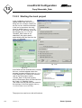
Operatable functions on pictures
when “All Pictures/Address Lists”
Lock selected addresses
Fig.2-6:
The ‘Operation’ field on the ‘Picture/list’ tab if ‘All pictures/ address lists’ is selected
Table 2: Meaning of the buttons in Fig.2-6 and the functions in Fig.2-7
Button
Acknowledge:
Explanation
Acknowledgement of alarms and release of limit-value
violations.
Switch command: Release switch commands
Setpoints:
Release adjustment of setpoints.
Limit values:
Release adjustment of limit values.
Counters:
Release adjustment of counter values
Available
pictures
Add a selected picture
or an address list to
the selection list
Functions released on
the picture/address
list
Select
functions
Pictures or an
address lists
assigned to user
Available address
lists
Remove an entry from
the selection list
Fig.2-7: ‘Assign pictures/address lists’
20
7000904003 Q2
Sauter Systems
novaPro32 Configuration
2
Password generation
Individual addresses can be blocked for the user in the ‘Inhibit addresses‘ input window.
Add pre-selected
addresses to the ‚Inhibit
addresses‘ list
Addresses denied to
the user
Fig.2-8: ‘Inhibit addresses’
2.3.4
HDB/Trend
You can set the access rights for the historical database (HDB) on the ‘HDB/Trend’ tab.
Release the HDB/Trend funcitons
Fig. 2-9: ‘HDB/Trend’ tab
7000904003 Q2
Sauter Systems
21
novaPro32 Configuration
2
Password generation
2.3.5
Time programme
Buttons are used to release the time programmes.
Select time programmes that can be changed by the user.
Table 3: Meaning of the ‘Time programme’ buttons
Button
Explanation
AS time programmes Time programmes for automation stations
PC time programme Time programmes from PC
Enable Time programmes
Fig.2-10: ‘Time programme’ tab
22
7000904003 Q2
Sauter Systems
novaPro32 Configuration
2
Password generation
2.3.6
Alarm list
You can use the ‘Alarm list’ tab to specify the user rights relating to alarm lists. Use
buttons to make the settings (see Fig.2-11).
Table 4: Meaning of the ‘Alarm list’ buttons
Button
Save setting
Call up picture/address list
Print
Close
Design for all users
Explanation
The settings made by the user
(such as column width, sorting
order, etc.) are saved.
The user can call up a picture or
an address list via a selected
message in the alarm list.
The user can print the alarm list
shown on the screen.
The user can close the alarm list
shown on the screen.
Release the alarm list
configuration
Fig.2-11: ‘Alarm list’ tab
7000904003 Q2
Sauter Systems
23
novaPro32 Configuration
2
Password generation
2.3.7
Calendar
The calendar tab (see Fig. 2-12) defines the user rights for the calendar configuration.
Use the ‘Open’ selection box to give users the right to read the calendar. ‘Edit’ also
allows a user to modify calendars.
Fig. 2-12: ‘Calendar’ tab
2.4
Default settings
When novaPro32 is installed, a user with the name Sauter and password 12345 is set
up automatically. The default user has the supervisor's rights, enabling him to set up
other user profiles.
When logging in for the first time, use the name and password of the default user and
then specify your personal user name and password.
Please ensure that at least one user always has the ‘Supervisor’ rights.
Delete the default user after you have specified the user name and password
for your own supervisor.
24
7000904003 Q2
Sauter Systems
novaPro32 Configuration
3
Filters
3 Filters
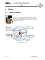
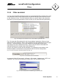
3.1
What are filters?
Filters are used to limit the data of an installation for a specified
application, i.e. to separate the essential from the inessential. By
selecting suitable criteria, filters can be used to make a selection
from the total stock of data.
Address filter
all addresses of the
'Electro' zone
all addresses of the
project
'Electro' zone
House addr.
'Bldg1*'
Result of filter:
all alarms of
the 'Electro' zone
in building no. 1
all addresses of
building no. 1
Address type:
'Alarm'
all alarms
Fig. 3-1: Schematic diagram of a filter
7000904003 Q2
Sauter Systems
25
novaPro32 Configuration
3
Filters
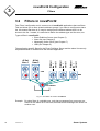
3.2
Filters in novaPro32
The ‘Filters’ configuration tool is common to all novaPro32 applications that use filters.
This tool allows you to form dynamic address groups; if you want to configure an alarm
list, this means that there is no need to assign each individual address that is to be
shown to the list – instead, it is sufficient to define the address type and the zone, etc.
Types of filter in novaPro32:• Event Publisher Server (see Chapter 5)
• Alarm list (see Chapter 6)
• Messaging Online (OLB) (see Chapter 7)
• HDB (see Chapter 8)
Printer/
fax/
e-mail
Al list
User 2
Printer/
fax/
e-mail
Al list
User 1
Printer/
fax/
e-mail
The application-specific filters for the Event Publisher Server and the alarm list can only
be parameterised or modified from the relevant application.
EP server
Fig. 3-2: How filters are used in novaPro32
Example: By using filters in a suitable way, only alarm messages from one zone are
shown on the alarm list of one user, whereas all the messages are shown for
another user.
26
7000904003 Q2
Sauter Systems
novaPro32 Configuration
3
Filters
For dynamic address selection in novaPro32, the following three types of filters are
available:-
•
•
•
Address filter (see Chapter 3.3.1)
AS monitoring filter (see Chapter 3.3.2)
AS group filter (see Chapter 3.3.3)
Fig. 3-3
3.3
Editing filters
3.3.1
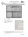
Address filter configuration
The ‘Address filter configuration’ window is used to parameterise filters for the dynamic
selection of addresses. Filtering criteria can be activated with the help of selection
boxes. At least one box (i.e. one criterion) must be active when you do this. The filter is
composed of the activated criteria added together (logical OR link).
A filter criterion is defined in the ‘Parameters’
fields by using wildcards and operators.
Depending on the filter criterion, various
operators are available (see Table 9: Operators
allowed for each parameter).
Procedure
1. Select the filter criterion: to do this, click on
the selection box with the left-hand mouse
button.
2. Position the cursor in the ‘Parameters’
field.
Fig. 3-4: The ‘Address filter configuration’
window
3. Enter the filter parameters: these may contain ‘wildcards’ (see Table 5: Filter wildcards)
and operators.
The ‘Operators’ button shows a selection of all the operators that are allowed in the
relevant parameter field.
The ‘Assistant‘ button opens the filter assistant - this is a Help program to show you
how to enter the filter parameters correctly (see Chapter 3.3.4).
There must always be a blank between the operator and the argument!
7000904003 Q2
Sauter Systems
27
novaPro32 Configuration
3
Filters
4. Save the configuration:
‘OK’ button:
‘Accept’ button:
The current filter is saved and the ‘Address filter
configuration’ window is closed.
The current filter is saved, but the ‘Address filter
configuration’ window stays open.
The ‘Result’ button shows all the addresses which are selected by the current
filter.
The selection boxes for empty filter criteria (no parameters defined) must be
deactivated. Otherwise, an error message will be shown when the filter is
saved (with the ‘OK’ or ‘Accept’ buttons) (see Fig. 3-5).
Fig. 3-5: Warning if parameters are missing or incorrect
Table 5: Filter wildcards
?
*
Replaces one character at a specified point in a character string.
Replaces the start or/and the rest of an expression that has been entered.
Table 6: Value ranges and format of the parameter fields
Parameter field
AS net name
AS name
AS number
House address
Address text
Address type
Extra address function
MFA
Zone
Category
28
7000904003 Q2
Field type
alphanumerical
alphanumerical
numerical 0... 31743
alphanumerical
alphanumerical
numerical 1
2
3
4
5
6
7
8
binary
Tick Box
set
numerical 0... 255
alphanumerical
numerical
Measurement
Setpoint
Alarm
Status
Quantity counter
Command
Binary feedback
Transfer (CFB_Soft)
All addresses with
parameterised extra function.
Sauter Systems
novaPro32 Configuration
3
Filters
Table 7: Value ranges and format of the parameter fields (only for AS group)
Parameter field
AS group name
Master/slave
Field type
alphanumerical
master,
Tick box set
slave
Tick box not set
MS name
Addresses selected are
either masters only or
slaves only.
Both master and slave
addresses are selected.
alphanumerical
Table 8: What the operators mean
Operator Call-up
Explanation
name
‘Text’:
from... Defines a value range
‘Text’
to
E.g.: Parameter for house address
B05.ac.a* : B05.ac.h* supplies all addresses in the indicated
value range, i.e. all addresses starting with B05.ac.a,
B05.ac.b,..., B05.ac.h.
AND
and
Logical AND link
E.g.: *Alarm AND *Ctrl supplies all addresses ending in ‘Alarm’ and
‘Ctrl’.
‘Text’ *
left
Defines flush left character sequence
E.g.: Parameter for address text
Klima* supplies all addresses which start with the address text
‘Klima...’.
* ‘Text’
right
Defines flush right character sequence
E.g.: Parameter for address text
*Alarm supplies all addresses ending in the address text
‘...Alarm’.
‘Text’ *
within Defines a sequence of characters within a text
‘Text’
E.g.: Parameter for address text
*GebaeudeNord* supplies all addresses containing the
sequence of characters ‘GebäudeNord’.
< number
<
less than
E.g: Parameter MFA
< 30 supplies all addresses with an MFA of less than 30.
<=
<=
none or equal to
number
E.g: Parameter MFA
<= 30 supplies all addresses with an MFA of less than 30 or
equal to 30.
> number
>
greater than
E.g: Parameter MFA
> 30 supplies all addresses with an MFA of more than 30.
>=
>=
greater than or equal to
E.g: Parameter MFA
>= 30 supplies all addresses with an MFA of more than 30 or
equal to 30.
<>
<>
not equal to/without
number
E.g: Parameter MFA
<> 11 supplies all addresses except those where MFA=11
7000904003 Q2
Sauter Systems
29
novaPro32 Configuration
3
Filters
3.3.1.1
X X
X X
X X
X X
X X
X X
left
right
within
X
X
X
X
X
X
X
X
X
X
X
X
X X
X X
X
X
X
X
X
X X X
X
X
X X
X X
=
<
<=
>
>=
<>
AND
* ? :
‘Text’*
*’Text’
‘Text’*’Text’
Parameter field
AS net
AS name
AS number
House address
Address text
Address type
Extra address function
MFA
Zone
Category
AS group name
from...to
and
Call up
Operator name
Table 9: Operators allowed for each parameter
X
X
X X
X X X X
X X
X X X X
X X
X X X X
X
X
Example
Examples of possible filter parameters.
The illustration opposite shows an
example for each parameter that is
available.
Fig. 3-6: Example of address filter configuration
If there is a blank in an alphanumerical field, the whole alphanumerical field
must be put in inverted commas ("").
The Filter Assistant is the ideal aid for parameterising the various fields; it is
advisable to use it.
30
7000904003 Q2
Sauter Systems
novaPro32 Configuration
3
Filters
3.3.2
AS supervisor filter configuration
AS filters are used for the dynamic selection of the self-monitoring function for
automation stations. The filter mask (see Fig. 3-7) is operated in the same way as the
‘Address filter configuration’ filter mask (see Chapter 3.3.1).
Fig. 3-7: ‘AS filter configuration window’
In the ‘Parameter’ fields, use wildcards and operators to define a filter criterion. Table 5 to
Table 9 show you the wildcards and operators that are available.
Procedure
1. Select the filter criterion: to do this, click on the selection box with the lefthand mouse button.
2. Position the cursor in the ‘Parameters’ field.
3. Enter the filter parameters: these may contain ‘wildcards’ (Table 5) and
operators.
The ‘Operators’ button shows a selection of all the operators that are
allowed in the relevant parameter field.
There must always be a blank between the operator and the argument!
The Filter Assistant is the ideal aid for parameterising the various fields; it is
advisable to use it.
4. Save the configuration:
The current filter is saved and the
‘OK’ button:
‘Address filter configuration’ window
is closed.
‘Accept’ button:
The current filter is saved, but the
‘Address filter configuration’ window
stays open..
The ‘Result’ button shows all the addresses which are defined by the
current filter.
The selection boxes for empty filter criteria (no parameters defined) must be de-activated. Otherwise, an error
message will be shown when the filter is saved (‘OK’ or ‘Accept’ buttons) (see Fig. 3-5: )
7000904003 Q2
Sauter Systems
31
novaPro32 Configuration
3
Filters
3.3.3
AS group filter configuration
AS group filters are used for the dynamic selection of addresses from AS groups. This
filter mask (see Fig. 3-8) is used in the same way as the ‘Address filter configuration’
mask (see Chapter 3.3.1).
In the ‘Parameter’ fields, use wildcards and operators
to define a filter criterion. Table 5 to Table 9 show you
the wildcards and operators that are available.
Procedure
Select the filter criterion: to do this, click on the
selection box with the left-hand mouse button.
2. Position the cursor in the ‘Parameters’ field.
3. Enter the filter parameters: these may contain
‘wildcards’ (see Table 5) and operators.
The ‘Operators’ button shows a selection of all the
operators that are allowed in the relevant
parameter field.
4. Save the configuration:1.
‘OK’ button:
The current filter is saved and the ‘Address filter
configuration’ window is closed.
Fig. 3-8: The ‘AS group filter
configuration’ window
‘Accept’ button:
The current filter is saved, but the ‘Address filter configuration’ window stays open.
The ‘Result’ button shows all the addresses which are defined by the current filter.
There must always be a blank between the operator and the argument!
The Filter Assistant is the ideal aid for parameterising the various fields; it is
advisable to use it.
The selection boxes for empty filter criteria (no parameters defined) must be deactivated. Otherwise, an error message will be shown when the filter is saved
(‘OK’ or ‘Accept’ buttons) (see Fig. 3-5: )
32
7000904003 Q2
Sauter Systems
novaPro32 Configuration
3
Filters
3.3.4
Filter assistant
You can call on the filter assistant to help you to parameterise filters. Position the cursor
in a parameter field for filter configuration, and use the left-hand mouse button to click
on the ‘Assistant’ button. The filter assistant offers you specific help on the parameter
field where you have positioned the cursor so that you can select the filter parameters.
Fig. 3-9: Example: Filter assistant for the ‘House address’ parameter field
Fig. 3-9 shows the filter assistant for the ‘House address’ parameter. After you have
launched the filter assistant, select a house address from the address tree and accept it
with the ‘>’ command button. The house address is automatically broken down
according to the house address structure. Click on the tick-boxes underneath the
individual characters to replace them with wildcards (?).
Use the ‘OK’ button to close the filter assistant. The selected house address, with
wildcards added, is transferred to the parameter field in the filter configuration.
Fig. 3-10 shows the result of the filter assistant from Fig. 3-9.
Fig. 3-10: House address filter with wildcards
In parameter fields ‘AS net name’, ‘AS name’, ‘AS number’, ‘Address type’, ‘MFA’ and
‘Category’, you can use the assistant to select from a list of possible entries.
Fig. 3-11: Filter assistant for the ‘Address type’ parameter field
7000904003 Q2
Sauter Systems
33
novaPro32 Configuration
3
34
Filters
7000904003 Q2
Sauter Systems
novaPro32 Configuration
4
Address groups
4 Address groups
An address group comprises one part of the address area of an installation. The
address area of an installation is easy to structure, according to virtually any criteria you
wish to choose.
Address groups are used in novaPro32 to configure the HDB server, the online
messaging and the alarm list. They allow you to select house addresses which are used
in the relevant section of the program.
4.1
Structure of an address group
When you set up a new address group, you must enter a name in the ‘Address group
name’ box (see Fig. 4-1). The newly selected name must not exist already, either as an
HDB group name, an online group name or an alarm list group name.
When you are editing an address group that exists already, the ‘Address group name’
field is shown with a grey background and the name of the group to be edited is
displayed.
4.1.1
Structure using filters
You can configure the composition of an address group with the help of filters. The
following procedure is advisable for this purpose (see also Fig. 4-1: Configuration of address
groups):
•
•
•
In the project structure (left box), open the ‘Filters’ directory.
Select the filter and accept it with control button No. 4.
In the ‘Result’ field (far right), you will see a list of all the project addresses selected
by the filter. This is a kind of interim result of the configuration.
Use command button No. 3 to copy selected addresses from the ‘Result’ field into
the ‘Selection’ field.
Drag the mouse with the left-hand button pressed down to select several addresses
at the same time and copy them into the ‘Selection’ field.
Command button No. 2 is used to remove addresses from the ‘Selection’ box.
When configuring the ‘Online Messaging’, filters can be
copied directly into the middle field, ‘Selected addresses,...’
with command button No. 1.
7000904003 Q2
Sauter Systems
35
novaPro32 Configuration
4
Address groups
You can start the filter parameterisation from the group configuration. To do this,
select the procedure described below:
Buttons:
Open:
•
•
•
In the project structure (left box), open the ‘Filters’ directory.
Select the filter and accept it with control button No. 5.
The ‘open’ button opens the ‘Address filter configuration’
window.
(see Chapter 3.3.1 Address filter configuration Page 27)
Delete:
• The ‘Delete’ button removes the selected filter.
New:
•
Set up a new filter. Choose from an address filter, an AS
monitoring filter or an AS group filter. The relevant
configuration window is opened (see Chapter 3.3.1, 3.3.2 and
3.3.3).
Address group name
Selection field
Project structure
Filter results
Fig. 4-1: Configuration of address groups
36
7000904003 Q2
Sauter Systems
novaPro32 Configuration
4
Address groups
4.1.2
Structure by individual address selection
An address group can be configured by selecting project addresses individually. The
following procedure is advisable for this purpose (see also Fig. 4-2):-
•
Open the project tree in the ‘Project structure’ field
Open folder ‘AS’ or ‘AS Groups’.
Now you can select addresses from the physical or logical address view
in the usual way.
Select address
Use the ‘>’ 1 command button to copy individual addresses into the
‘Selection’ field and the selected addresses can be removed using the ‘<’
button 2.
The ‘Result’ button lists all the addresses linked to the address group.
Confirm the address selection with ‘OK’.
-
•
•
•
Fig. 4-2: Selecting an address from the project tree
7000904003 Q2
Sauter Systems
37
novaPro32 Configuration
4
38
Address groups
7000904003 Q2
Sauter Systems
novaPro32 Configuration
5
Event Publisher Server
5 Event Publisher Server
The Event Publisher Server (EP server) collects messages from the automation stations
and sends them to the messaging systems on the next higher level (see Fig. 5-1).
The Event Publisher Server spools the last state of every address shown in the alarm
list (alarms, limit-value violations, acknowledgements, normal state) as well as system
messages (e.g. status of the automation station, etc.) and sends them immediately to
the higher-level services.
Just after the EP server has been started up, an automatic refresh of all addresses
configured takes place, i.e. all addresses configured are read once. The EP server sets
all addresses configured to the ‘spontaneous’ status in the automation station.
5.1
How it works
In order to display alarm lists on your PC, the program EP server.exe has to run in the
background.
Address groups of the EP server limit the number of open addresses. This limits traffic
on the network and prevents overloads.
Alarmliste
Mail
Printer
GSM
SMS
Pager
Fax
Voice
Files
Logbuch
Internet
email
Event-Publisher-Server
WAN
$
Kommunikation
$
$
WAN
Fig. 5-1: The Event Publisher Server as a link between process data network and messaging channels
7000904003 Q2
Sauter Systems
39
novaPro32 Configuration
5
Event Publisher Server
5.2
Configuring the EP server
The EP server should be configured by either the System Administrator (Supervisor) or
a specially authorised user. (To assign authorisation rights, see Fig.2-4/Page 18)
The ‘EPServer configuration’ window can be opened via File | Configuration Î EP
server.
Event Publisher Server
Selection of alreadyconfigured filters
Active filters of the
Event Publisher
Active functions of the
selected ‘control’ filters
Fig. 5-2: EPServer configuration
Table 10: Short cuts
Short cuts
A
S
R
C
LV-...
MW
SW
MZ
HC
...TV
40
7000904003 Q2
M
P
N
B
Alarm
Status
Feedback
Command
Limit Value
Measurement
Setpoint
(Quantity) Counter
CFB-Soft
Hours-run counter
Total Value
Sauter Systems
novaPro32 Configuration
5
Event Publisher Server
Table 11: Symbols
Symbols
Main function only
Additional function only
Complete set of functions
5.2.1
Create a new Event Publisher filter
1) The ‘New’ button of the ‘EP Server Configuration’ window (see Fig. 5-2) opens the
‘filter parameterising’ window . Choose between an address filter, an AS monitoring
filter and an AS group filter. The relevant parameterising window then opens (see
Chapter 3.3.1, 3.3.2 and 3.3.3).
The newly parameterised filters are filed automatically in the ‘Filter/System Group
Filter’ folder and are shown under ‘Available filters/LG’ in the ‘EPServer
configuration’ window (see Fig. 5-2).
2) Using the
button, you can add a filter selected under ‘Available filters’ to the list
of active filters.
button does the opposite. It removes a selected filter from the list of active
The
filters. The filter merely becomes inactive, i.e. it remains stored in the ‘System
Group Filter’ folder.
3) Enable the functions of the active filters:3.1) Choose the filters
(see Fig. 5-2 EPServer configuration selected filter ‘temperatures’)
3.2) Activate the functions by clicking the relevant tick-box.
(Abbreviations: see Table 10)
All active filters of the Event Publisher server are listed in the ‘EPS-Filter/LG’ field of
the ‘EPServer configuration’ window (see Fig. 5-2 EPServer configuration). Symbols
show the functionality of the addresses (Table 10).
Several filters can be parameterised for each EP server.
4) ‘OK’ saves and terminates the configuration.
‘Apply’ saves the actual configuration, the ‘EP Server Configuration’ window
remains open and the ‘Result’ button becomes active.
The ‘Result’ button lists all addresses configured on the actual EP Server (see 5.2.3
Show addresses of the Event Publisher server).
7000904003 Q2
Sauter Systems
41
novaPro32 Configuration
5
Event Publisher Server
5.2.2
Edit an Event Publisher filter
In the ‘EP Server Configuration’ window, you can edit, rename, copy or delete Event
Publisher Server filters.
1) Mark an active filter in the part of the window headed ‘EPS filter/LG’.
2) Button
Depending on the type, the ‘Address filter parameterising’
• Open
window (see 3.3.1), ‘AS filter parameterising’ (see 3.3.2) or
‘AS group filter parameterising’ (see 3.3.3) is opened with
the selected filter. The filter parameters can now be
changed. On exiting the ‘Address filter parameterising’
window, the new filter parameters are saved under the
same name. The filter selected at the beginning is,
therefore, changed.
The parameterising window corresponding to the filter type
• Copy
is opened with the selected filter. In contrast to the ‘Open’
button, a new filter name can now be given. All parameter
changes are saved under the new filter name on exiting the
‘Filter parameterising’ window. The old filter remains
unchanged.
The new filter is automatically stored in the
‘System Group Filter’ folder. To activate it, it has
to be copied to the list of active filters using the
‘>’ button (see chapters 5.2.1 - 5.2.2).
42
•
Delete
•
Rename
7000904003 Q2
The selected filter is deleted.
This function deletes the filter both from the list
of active filters and from the ‘System Group
Filter’ folder.
To remove a filter only from the list of active
filters, click the ‘<’ button (see chapter 5.2.1).
The parameterising window corresponding to the filter type
is opened with the selected filter. Apart from the filter name,
all parameters are shown inactive. The filter name can be
changed. The filter is saved under the new name on exiting
the ‘Address filter parameterising’.
Sauter Systems
novaPro32 Configuration
5
Event Publisher Server
5.2.3
Show addresses of the Event Publisher server
After completing the Event Publisher configuration, you can display a detailed view of
the current EPServer settings by clicking the ‘Result’ button, i.e. all addresses selected
by the active filters are listed.
If the ‘Result’ button is displayed light, you have to activate the new
configuration first, by clicking the ‘Apply’ button.
Header of the
table
Name of the EP Server
Number of addresses in the
EP Server
Addresses in the
Symbol of the
addresses
Function symbol
Text of the addresses
Function symbol
Fig. 5-3: Result of an EPServer configuration
Symbols in the far-left column of the result list show the functionality of every address.
For an explanation of the symbols: see Table 11 page 41.
Symbols of active addresses are displayed in black. Red symbols stand for functions,
which are released in novaPro32 but not released in the automation station (AS). You
have to release the function in the AS by using the FBD-Editor.
By left-clicking on the cells of the table header, you can change the sorting order of the
entries displayed.
Example:
7000904003 Q2
Clicking into the ‘Name’ cell sorts the list by the address name in
alphabetical order. Clicking again into the same cell changes the sorting
order from descending to ascending.
Clicking into the ‘Designation’ cell sorts the list by address text.
Sauter Systems
43
novaPro32 Configuration
5
44
Event Publisher Server
7000904003 Q2
Sauter Systems
novaPro32 Configuration
6
Alarm list
6 Alarm list
The alarm list in novaPro32 is user-oriented, i.e. alarms and limit-value violations are
only shown for those addresses which are released for
the particular user.
Addresses are released for a specified user by the
System Supervisor or by a user who has ‘Password
generation’3 authorisation on the ‘Picture/list’ tab in the
‘Password properties’4 window.
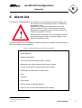
!
When the alarm list is open, the current status is shown
continuously with the help of a warning triangle in the
Microsoft Windows icon bar.
Because the alarm list is individually matched to the user, it provides a rapid overview of
the current status of the installation.
Table 12: Information that can be shown in an alarm list
• Date and time of occurrence
• House address
• Address designation
• Text of the last status shown (alarm, normal)
• Measured value which caused the limit-value violation
• Counter value which caused the limit-value violation
• Dimension for measured or counter value
• Zone
• Category
• Limit values
• Date and time of acknowledgement
• Name of the user who acknowledged the message
3 see Table 1: page 16
4 see Fig.2-5‘Picture/List’ tab page 19
7000904003 Q2
Sauter Systems
45
novaPro32 Configuration
6
Alarm list
6.1
Configuration
An alarm list is configured by following these steps:1. Grouping in the Event Publisher Server:
The Event Publisher Server is used to release those addresses which automatically
transmit a change in status or value to novaPro32. An address group is formed for
this purpose with the Event Publisher Server.5
2. Call up the "Alarm list configuration"
window from the "File | Configuration
Î Alarm list" menu (see Fig. 6-1)
3. On the "Users" tab, use the left-hand
mouse button to select a user profile.
4. Now use the "Window", "Print",
"Address Group" and "Acoustic
Signal" tabs to configure the
individual alarm list.
Fig. 6-1: Alarm list configuration – User tab
6.1.1
Select user profile
An individual alarm list profile comprising a window template, a print template and an
address group is selected for each user on the "Alarm list configuration user tab" (see
Fig. 6-1).
The tab shows all the currently defined user profiles in alphabetic order. Click in the
table header to change the sorting sequence from ascending to descending (this is
operated like the MS Windows Explorer).
In the "Window template" column, you see the window templates that are currently
assigned. Click on a window template to see a selection of templates that have already
been defined.
The print template and the address
group are selected in the same way
as the window template.
In the "Acoustic Signal" column, you
can individually switch the acoustic
alarms on or off for each user.
F
ig. 6-2: Selection of pre-defined window templates
5 see Chapter 5 Event Publisher Server
46
7000904003 Q2
Sauter Systems
novaPro32 Configuration
6
Alarm list
Click on the ‘Result’ button to see all
the addresses assigned to the
selected user.
The alarms which belong to an AS
and no longer respond to a novaNet
network are shown with a background
which corresponds to the data point.
Fig. 6-3: Result of the alarm list configuration
6.1.2
Specifying the alarm list presentation
You can use the "Window" tab to define the screen presentation of the alarm list
individually for each user (see Fig. 6-4).
The settings you have made are stored under a template name.
"Select column" area of the
window:
defines the meaning of the
columns shown in the alarm
list.
"Font" area of the window:
Specifies the font for the
alarm list
"Pop to foreground" selection box:
If this function is selected,
an alarm list located in the
background will
automatically "jump" to the
foreground if a new alarm or
a limit-value violation
occurs.
7000904003 Q2
Fig. 6-4: Alarm list configuration – Window tab
Sauter Systems
47
novaPro32 Configuration
6
Alarm list
6.1.2.1
Modify an existing window template
1. Select the columns to be shown in the "Select columns" area of the window.
•
You can use the
button to copy an entry that you have selected from the
"Available columns” list into the "Selected columns” list.
•
The
•
You can use the
and
buttons to change the sequence of the selected
columns.
The list entries are shown from left to right in the alarm list, i.e. the top entry is
shown in the alarm list as the far-left column, and the bottom entry appears as
the far-right column.
button is used to delete an entry from the "Selected columns" list.
2. Select the fonts in the "Design, font setting" area of the window.
• Use the "Select" button to open the
"Font" window shown opposite.
• Select the font you want to display in
the alarm list. All the fonts installed
on the relevant PC are available for
you to choose from.
• Confirm your selection with "OK".
• "Cancel" rejects all the new settings
you have made.
Fig. 6-5: Alarm list – font setting
3. Save the window configuration as a new
template:
• In the "Design" area, enter the
template name.
To do this, select the template name
shown at the moment and overwrite
it with a new name.
• Confirm your entry with the "New"
button. A brief summary of the
settings you have made will now
appear. Confirm the dialogue
opposite with "OK".
• The ‘Delete’ button removes the
template that is currently selected.
Fig. 6-6: New alarm window model
48
7000904003 Q2
Sauter Systems
novaPro32 Configuration
6
Alarm list
6.1.2.2
Modify an existing window template
1. Select an existing window template in the "Design" area of
the window.
2. Select the columns to be shown in the "Select columns" area
of the window (like 6.1.2.1 Modify an existing window template
paragraph: 1).
3. Select the fonts in the "Design, font settings" area of the
window (like like 6.1.2.1 Modify an existing window template
Fig.6-7: Select template
paragraph: 2).
4. Save the window configuration.
Confirm your entry with the "Accept" or "OK" buttons.
The ‘Delete’ button removes the template that is currently selected.
6.1.3
Define a print template
Use the "Print template" tab to define
the presentation of the alarm list printout.
As with the screen presentation
("Window" tab), the templates defined
here can also be individually assigned
to specific users6
Fig. 6-8: Alarm list configuration – Print tab
6.1.3.1
Create a new print template
1. Select an existing print template (see Fig. 6-8).
2. Use the "Open" button to start the "Designer" auxiliary program from "List and
Label". The print template can now be adapted to your personal requirements (see
Fig. 6-9).
3. Save the file template under a new name (menu: File | Save as...) and close "List
and Label".
4. Confirm the configuration with the "OK" button on the "Print" tab.
6 see Chapter 6.1.1 Select user profile
7000904003 Q2
Sauter Systems
49
novaPro32 Configuration
6
Alarm list
6.1.3.2
Modify an existing print template
1. Select an existing print template (see Fig. 6-8).
2. Use the "Open" button to start the "Designer" auxiliary program from "List and
Label". The print template can now be adapted to your personal requirements
(see Fig. 6-9).
3. Save the file template (menu: File | Save) and close "Designer".
4. Confirm the configuration with the "OK" button on the "Print" tab.
Fig. 6-9: Creating a print template with Designer from List and Label
6.1.4
Specify an address group
The "Address group" tab represents the access to the configuration of address groups
for the alarm lists.
Alarm list address groups specify the actual content of an alarm list. By using a group,
you can separate a section of the installation, a zone or a functionality from the overall
address area for the installation and you can show it in a specific alarm list.
A group can also be matched to the task and sphere of influence of a specific user. For
example, it is possible to suppress alarms from the "Light" section of the installation on
the heating technician's alarm list. Targeted suppression of alarms outside of the user's
sphere of influence plays a major part in increasing clarity.
Working with address groups: see Chapter 4 Address groups
50
7000904003 Q2
Sauter Systems
novaPro32 Configuration
6
Alarm list
The Editor‘s
functions
Choose one of
the defined
address groups
Fig. 6-10: Alarm list configuration – "Address group" tab
Table 13: Editing functions
7000904003 Q2
•
New
•
Open
•
Copy
•
•
Delete
Rename
Opens a new "Groups" window (see Chapter 4). You can
set up a new address group and save it under any name
you want.
The "Groups" window (see Chapter 4) is opened with the
selected address group. You can modify the group and it is
stored under the same name when you exit.
The "Groups" window (see Chapter 4) is opened with the
selected group. Unlike the "Open" button, this makes it
possible to enter a new group name. All parameter changes
are stored under the new name when you exit from the
group configuration. The old group remains unchanged.
The selected group is deleted.
The "Groups" window (see Chapter 4) is opened with the
selected group. The group name can be changed. The filter
is saved under the new name when you exit from "Address
filter configuration".
Sauter Systems
51
novaPro32 Configuration
6
Alarm list
6.1.5
Acoustic signal
On the ‘Acoustic signal’ tab (see Fig. 6-11), you specify the settings for the acoustic
alarms. An acoustic alarm tone can signal the occurrence of an alarm (incoming alarm).
You can assign an individual sound signal in the form of a Windows media file (*.wav,
*.mdi, *.rmi) to each category (0 ... 14). The file is played once or is repeated when the
alarm occurs, as you choose.
Fig. 6-11: Alarm list configuration – Acoustic Signal tab
•
•
•
•
52
Select an address category to which you want to assign an acoustic signal.
The ‘...’ button opens the Windows file browser. Select a Windows media file
(formats: *.wav, *.mdi, *. rmi) from your hard disk.
‘Cycle’ switches on repeated playing of the sound file.
‘Repetition’ switches an alarm that has finished back on again after the set time,
until the switch-off condition in the ‘General’ field is satisfied.
•
Use the
•
In the ‘General’ field, you can specify the conditions under which the acoustic
alarm sound is switched off.
7000904003 Q2
buttons to check the acoustic signal.
Sauter Systems
novaPro32 Configuration
7
Messaging
7 Messaging
Messaging covers the alarming and reporting system of the EY3600 building
management system. It belongs to the Event Publisher Server7 and is configured from
within novaPro32. Thanks to this structure, alarms and reports are generated even
when novaPro32 is inactive; only the EPServer.exe program has to be active on the
PC.
The alarming and reporting system (messaging) can be configured according to the
specific needs of a project or a user. novaPro32 controls access rights. This effectively
prevents configuration and manipulation errors caused by unauthorised users.
The configuration is done based on address groups and events.
novaPro32 supports alarming and reporting devices as mentioned in Table 14 .
Table 14: Alarming and reporting devices supported by novaPro32
Printer
Fax
E-mail
File
Line printers supported by Windows such as Epson FX...
Faxes can be sent with MS-Exchange (Postoffice) of Windows
E-mails can be sent with MS-Exchange of Windows
Alarms and reports can be saved in an ASCII file. The file can
be used as an interface to third-party systems.
Table 15: Events supported
Type of
address
Alarm/Status
Binary feed
back signal
Measurement
Counters
Setpoints,
Control Signals
Events supported
Any change of state
Any change of state (e.g. changes in the states ON, OFF, 1, 2,
3, 4, 5, 6, Auto, Local)
Limit-value violations, returning to normal range,
acknowledgement
Limit-value violations, returning to normal range,
acknowledgement
Limit-value violations, returning to normal range,
acknowledgement
7 see Chapter 5 Event Publisher Server
7000904003 Q2
Sauter Systems
53
novaPro32 Configuration
7
Messaging
7.1
Configuration
Menu (File | Configuration Î Messaging) opens the tabs for the configuration of the
alarming and reporting system (see Fig. 7-1).
When you configure the ‘Messaging’ for the first time, it is recommended to
configure the ‘Output device’ and ‘Output Layout’ tabs first.
Finally, the ‘Messaging Profile’ tab assigns an output device and an output
layout to an address group.
After the configuration has been completed, the Event Publisher Server
(EPServer.exe) has to be restarted. The EP server is initialised with the new
configuration.
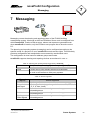
7.1.1
The ‘Output Device Assignment’ tab
The ‘Messaging Profile’ tab can be
divided into two sections:1. Definition of the address group 8
Meaning of the buttons
New
Creates a new address
group.
Open Opens an already existing
address group.
Delete Deletes the address group
selected.
Rename Renames the address
group selected.
Result Shows all addresses of the
group selected (see Fig. 7-2)
Fig. 7-1: Output Device Assignment
2. Assignment of an output device and a template to an address group.
An assignment table defines output channels for every single address group. An output
channel consists of one line in the assignment table. Output device and template can be
selected by clicking the cells of the table.
8 Configuration of an address group: see Chapter 4 Address groups
54
7000904003 Q2
Sauter Systems
novaPro32 Configuration
7
Messaging
Table 16: Columns in the assignment table
Type
Output device
Template
Disable
Time
programme
Defines the type of the output device (line printer, e-mail/fax or
file).
Defines the output device. You can select one of the profiles
configured on the ‘Output device’ tab (see Fig. 7-3 to Fig. 7-15).
Defines the output template. You can select one of the
templates configured on the ‘Output layout’ tab.
An output channel may be disabled temporary.
Yes: Disables the channel
No: Enables the channel.
Select an EP time programme. The EP time programme enables
and disables the output channel at defined dates.
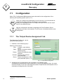
The result (content) of an
address group is displayed
in a table (see Fig. 7-2).
Addresses displayed in light
writing without symbol in the
first column are addresses
that are excluded by the
filter of the Event Publisher
Server. These addresses
are not available for
Messaging.
Fig. 7-2: Content of an address group
Table 17: Symbols of the first column
The complete set of functions of an
address is selected.
Only the basic function of an address
is selected.
Only the additional function of an
address is selected.
Symbols in red stand for functions that have
not been configured in the automation station
(AS).
7000904003 Q2
Sauter Systems
55
novaPro32 Configuration
7
Messaging
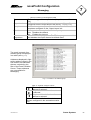
7.1.2
The ‘Output Device’ tab
On the ‘Output Device’ tab, real
devices, such as printers, fax
numbers, e-mail addresses,
path and file names on data
media have to be assigned to
the various output devices.
All devices assigned to the
output device selected are listed
in the lower section of the tab.
Fig. 7-3: Defining the output devices
Various output media can be selected using the buttons.
Line printer:
Mail/fax receiver:
File
see Fig. 7-7 and
Chapter 7.1.2.1 Line printer
see Fig. 7-17 and
the ‘EY3600 novaPro32 Installation’ manual,
no. 7000 915 003
see Fig. 7-21
If the ‘Disable Messaging’ function has been activated, no data are sent to the various
output media.
If the ‘Disable Messaging at EP Server Start’ function has been activated, only those
alarms that have reported since the system was started up are edited. The messages
that were edited before the application was closed are no longer taken into account.
56
7000904003 Q2
Sauter Systems
novaPro32 Configuration
7
Messaging
7.1.2.1
Line printer
7.1.2.1.1 Introduction
As from novaPro32 Version 5, up to five Windows printers can be used (with
continuous-form paper) by the system as line printers for printing out the online
notifications.
To install the printers, refer to Chapter 3.5 ‘Printers for novaPro32’ of the
Installation manual (7 000915 003 P12).
7.1.2.1.2 Specific settings
In the ‘Printers’ window of the Windows System Manager, use the right-hand mouse
button to call up the ‘Server Properties’ (see Fig. 7-4).
Ensure that no printer is selected when you call it up.
Fig. 7-4: Calling up the ‘properties’ of the Windows NT print server
The dimensions of the form must not exceed the margins/printable area of the
printer, otherwise the form will not be available to the printer.
7000904003 Q2
Sauter Systems
57
novaPro32 Configuration
7
Messaging
•
For each printer used, add a new form as shown in the example in Fig. 7-5. The paper
source must be adjusted as shown in Fig. 7-6.
Fig. 7-5:
Setting up a new paper format
•
Fig. 7-6: Paper source in Windows NT/2000 or XP
Configuration of the printer in novaPro32 online messaging:
(see Chapter 7.1.2 The ‘Output Device’ tab)
Please check these points when carrying out the configuration:a) The printer adjustments for "Paper intake" and "Paper format"
From the printer settings, select the paper format which you set up above
(such as EY3600_1). At "Paper intake" select "Tractor intake".
a) The "Paper intake" and "Paper format" in the Graphic Editor.
7.1.2.1.3 Defining an online printer
Depending on the type of output medium that has been selected, all assigned output
media are listed in the ‘Select output media’ zone in Fig. 7-3.
The ‘Edit’ button, see Fig. 7-7, opens the
configuration window.
The ‘New’ button is used to set the new
output printer.
A network printer can also be assigned.
The printer selected in the list can be
removed using the ‘Delete’ button’ or
amended using the ‘Edit’ button’.
Name of physical printer
Name given by user
Fig. 7-7 Line
58
7000904003 Q2
printer
Sauter Systems
novaPro32 Configuration
7
Messaging
Creating a new printer, e.g. ‘Watchman’.
The ‘New’ button opens a window in which
the use can enter a name for the printer
(see Fig. 7-8).
Fig. 7-8: Dialogue
On confirming with ‘OK’, the dialogue box
for choosing the relevant Windows printer
opens.
If you press the ‘Select...’ button, all the
printers installed under Windows are listed.
(Fig. 7-10).
Fig. 7-9: Select printer
For online notification, it is essential that you choose the ‘Printer PageIndependent’ mode.
All the printers installed under Windows are
listed in the window, including network
printers.
Press ‘OK’ to confirm your choice.
Fig. 7-10: Printer set-up
A physical printer that has already been
chosen as a protocol printer cannot be used a
second time. It cannot also be used as a line
printer at the same time.
A message to this effect then appears.
7000904003 Q2
Fig. 7-11 Warning against double usage
Sauter Systems
59
novaPro32 Configuration
7
Messaging
The configured printer appears in the list Fig.
7-12.
All listed printers can be used as output
media for the EP server.
Fire Service
Reception
Fig. 7-12: Online printer selection
Up to five printers can be defined. A message
appears when the limit has been reached.
Fig. 7-13 Message warning of printer limit
On pressing the ‘Graphic Editor’ button, there
appears a window in which the defined line
printers are listed (Fig. 7-14). Choose one of
these printers and right-click; a dialogue box
appears, allowing you to carry out a test or call
up the graphic editor.
Fig. 7-14 List of EP line printers
The ‘Printer Test’ function is used to print
out the up to 30 patterns (font, size and
colour) of the chosen print template.
These can be edited using the ‘Graphic
Editor’ button in Designer.
Fig. 7-15 Print template
60
7000904003 Q2
Sauter Systems
novaPro32 Configuration
7
Messaging
If this message (Fig. 7-16) appears when
you choose either the ‘Printer Test’ or
‘Graphic Editor’ button, this means that the
Event Publisher, Alarm Server was
selected when the start icon was created.
Fig. 7-16
7.1.2.2
E-mail and fax
For the configuration of an e-mail or a fax,
you have to select an address or a fax
number from an address book installed in
Windows.
The section on the left shows the content
of the address book selected. The ‘New...’
button lets you create a new address book
entry. The ‘Properties’ button lets you edit
an address book entry (edit mail address,
fax number, etc.).
The section on the right shows the
addressees. A message generated by the
Event Publisher is sent to all recipients
listed in the right-hand section.
E-mail and fax recipients may be mixed in
this list.
7.1.2.3
Fig. 7-17: Address book for fax and e-mail
Files
Path and file names of the
‘File’ output device are
listed.
New path and file names
can be created by leftclicking the blue symbols in
the ‘Path’ column.
Fig. 7-18: File (Pager Interface)
7000904003 Q2
Sauter Systems
61
novaPro32 Configuration
7
Messaging
The ‘Number Messages’ column defines file size, i.e. the number of messages saved in
the file (values allowed: 100 – 1000).
The ‘Reorg.’ column defines how the file is reorganised if the file reaches the size
defined in the ‘Number Messages’ column (values allowed: 25% - 75%). A value of e.g.
25% means: if the file size reaches the number of messages defined, the oldest 25% of
the messages will be removed.
7.1.3
The ‘Output Layout’ tab
A template defines what kind of
information and in what form it is
sent to the output device.
The ‘Output Layout’ section lists all
templates available for the Template
Type selected.
With the buttons on the right, you
can create new templates, and edit
or delete existing templates.
Fig. 7-19: Output Layout
The window for the configuration of a template consists of the ‘Layout’ and ‘Message’
sections (see Fig. 7-20).
The ‘Message’ section of the table defines how the messages are displayed. The table
entries are explained in Table 18.
Table 18: Design of a template
Column
Event
Background
Text
Font
Additional Text
Additional File
62
7000904003 Q2
Explanation
Select an event that causes an entry in the template and a
message from the Messaging system.
Defines the text background colour
Defines the text colour
Defines font and size
Defines an additional text that is sent with the message.
Defines an additional file that is sent as an attachment with the
e-mail.
Sauter Systems
novaPro32 Configuration
7
Messaging
Fig. 7-20: Configuring a mail, fax template
Left-click a cell of the table or on the blue symbol; this opens a selection of possible cell
entries. So the configuration of the table is self-explanatory.
The ‘Layout’ section defines what kind of information is sent with the message. All
possible information is listed in the ‘Available lines’ field.
The field on the right shows the layout of a message with the information selected.
The ‘>’ button copies a line selected in the ‘Line selection’ field into the layout. The ‘<’
button removes an entry from the layout. Optional commands can be added to each line.
To do so, left-click a cell of the ‘Editable column’ and enter text of up to 40 characters.
Right-clicking a cell of the ‘Editable column’ opens a context menu for the text format.
The
and
buttons change the line order of a message.
The ‘Headline ...’ tick box activates (or de-activates) the yellow title bar.
The configuration of a file-template can be done in a similar way. But the ‘Font’ cells etc.
are not available.
7000904003 Q2
Sauter Systems
63
novaPro32 Configuration
7
Messaging
7.1.4
EP time programme
With the EP time programme, you can
enable and disable an output channel
in accordance with a time programme.
You can enable a printer at business
hours only or you can redirect all
messages to a home fax number at
weekends, see Fig. 7-22.
Fig. 7-21: The output time profile
The internet e-mail function used by novaPro32 is no longer supported by
Windows 2000 and XP.
7.1.4.1
Creating and configuring an EP time programme
In field n you can choose all configured
time programmes.
On right-clicking in zone o, the context
menu appears.
The functions of the various menu items:• Edit: Lets you create a new time
programme.
• New command: Lets you create a
new command line for the EP time
programme.
Fig. 7-22 The output time profile
• Edit command: Lets you edit an existing command line.
• Copy: Lets you copy an existing programme and, using the ‘Insert’ function, copy it
to a time programme selected from the list.
• Delete: Lets you delete the chosen command line.
• Suspend: Lets you disable one or more command lines manually. The disabled task
is marked with an ‘X’ in the ‘S’ column.
• Release: Revokes the suspension.
• Calendar: Lets you view and edit the assigned calendar.
64
7000904003 Q2
Sauter Systems
novaPro32 Configuration
7
Messaging
7.1.4.1.1
Edit
The ‘Edit’ function opens the window shown in Fig. 7-24.
Press ‘New’ to view the dialogue box for entering the
name of the EP time programme.
For example: Activate SMS
Fig. 7-24
Fig. 7-23
Once you have confirmed the name, it appears in the
relevant column. A calendar chosen from the list can
now be assigned to this time programme. The system
calendar is assigned by default.
In the ‘Time Range not defined’ field, you can block or
enable all commands of all EP time programmes for the
non-parameterised time ranges.
Fig. 7-25
The chosen mode is shown in field p, see Fig. 7-22.
A selected time programme with a parameterised
command line is shown in the background window on
activating the ‘Show’ function. This programme can now
be copied with the command line.
The copy appears in the chosen line of the list Fig. 7-26.
An EP time programme can also be amended or
deleted using the relevant button.
Fig. 7-26
7.1.4.1.2
New command
The ‘New’ button opens the ‘Execution’ window, in
which the Type, Date, Time period, Command, Day and
Comment can be defined.
When a type has been selected, the relevant
parameterising zone appears.
The ‘hourly’ mode is not allowed.
Fig. 7-27
7000904003 Q2
Sauter Systems
65
novaPro32 Configuration
7
Messaging
1. ‘once’
From...to
Hour : 0 – 23
Minute : 0 – 59
Command: free or locked
on
7.1.4.1.3
:
1 – 31
1 – 12
2000 – 2099
*
Æ day of month
Æ month
Æcalendar year
Æevery year
Fig. 7-28
Comment
Text can be entered in this field.
Fig. 7-29
If you right-click the word ‘Comment’, a dialogue
window appears in which you can enter formatted text,
see Fig. 7-31.
The text is limited to 255 characters. A message
(Fig. 7-32) appears when the limit is reached.
Fig. 7-30
Fig. 7-31
Fig. 7-32
2. ‘daily’
From...to
Hour : 0 – 23
Minute : 0 – 59
Command: free or locked
Fig. 7-33
66
7000904003 Q2
Sauter Systems
novaPro32 Configuration
7
Messaging
3. ‘weekly’
From...to
Hour : 0 – 23
Minute : 0 – 59
Command: free or locked
Fig. 7-34
Select day
The chosen days are activated:
= active
Fig. 7-35
4. ‘monthly’
From...to
Hour : 0 – 23
Minute : 0 – 59
Command: free or locked
Fig. 7-36
every (each):
In this window you can set the day on which the
programme is to be executed.
You have the choice between the first and the last
day of the month...
Fig. 7-37
of the month:
...or between the first and the fourth or the last day of
the week of the month (from Monday to Sunday)
Fig. 7-38
7000904003 Q2
Sauter Systems
67
novaPro32 Configuration
7
Messaging
For example:
th
Every 4 Monday of the month.
Every last Sunday of the month.
Fig. 7-39
Fig. 7-40
If the number in the ‘each’ field is too big (e.g. every 5th Monday of the month), the
following message appears:-
The command is carried out only if such a day really exists.
For instance, every ‘31.’ of the month ‘day’ Î The command is carried out only
if the month has 31 days.
68
7000904003 Q2
Sauter Systems
novaPro32 Configuration
7
Messaging
7.2
novaPro32/Micromedia Alert
Together with EY3600 novaPro32, the Micromedia Alert program makes it possible to
manage alarms and the on-call service. Alert can be used to notify the on-call staff of
events such as alarms, limit-value violations, etc. through various communication media:
telephone, pager, SMS, fax and e-mail.
The next chapter describes the parameterisation on the novaPro32 side as well as the
settings on the Alert side. 9
EPP
7.2.1
Configuration of novaPro32
The EPP files for online messaging in novaPro32 represent the interface with the ‘Alert’
alarm program. Use of the alarm event list and alarm acknowledgement functions in the
‘Micromedia Alert’ program must be configured differently from the main alarm message
and on-call plan functions.
7.2.1.1
Main function
Set up one EPP file for each on-call group. To do this, go to the ‘Configuration’ menu in
novaPro32 and select the ‘Online messaging’ command
Setting up the EPP file:
The EPP file represents the interface between novaPro32 and Micromedia Alert. Alert
regularly checks the date and time of the last change to the file. If the file date is
different, Alert automatically analyses the contents of the file. The EPP file contains only
spontaneous reports of alarms and limit-value violations (incoming alarm). The changes
from alarm status to normal status and acknowledgements are not recorded.
1. On the "Output medium" tab (see Fig. 7-41) select "File" as the "Output media type"
and then click on the "Edit" button.
2. In the "File (Pager interface)" dialogue (see Fig. 7-42), click on the icon under "Path"
and enter the path and filename for the EPP file. Note the file extension .epp.
9 see auch Benutzerhandbuch von Micromedia Alert
7000904003 Q2
Sauter Systems
69
novaPro32 Configuration
7
Messaging
Fig. 7-42
Fig. 7-41
3. Specify the number of messages per file (between 100 and 1000) and the
reorganisation (between 25% and 75%) , and close the settings with "OK".
4. Now, in the "Event Publisher Configuration" window, go to the "Output template" tab
and select the "File" template type, then open the "File template" window by clicking
on the "New" button.
5. Name the template in the "Template name" box (see Fig. 7-43).
6. In the "Layout" field, select reporting of all active alarms and limit-value violations by
selecting this line: AL LV coming/ON/FB '''1,2,3,4,5,6'''.
Create a template for each type of event.
You have to specify the contents of the message in the „Layout“ box. Tick the Option
"Headline (Date/Time and Comment) " to show the headline (yellow background)
"Message from Building ... ". This text can then be edited and should be shortened.
(See Fig. 7-43).
7. Next, in the "Event Publisher Configuration" window, go to the "Assign output
medium" tab and activate the option: "Online messaging is active" (see Fig. 7-44).
8. Create a logical group if one does not already exist.
9. Select the logical group whose events should be transferred to "Alert"; at "Type",
select "File"; at "Output devices" select the EPP file that was created previously; at
"Template" select the output template that was previously created, and at "Disable"
select ‘No’.
If several logical groups should be transferred to "Alert", you must carry out the
parameterisation for each individual group.
70
7000904003 Q2
Sauter Systems
novaPro32 Configuration
7
Messaging
The Event Publisher configuration does not become active until the Event
Publisher Server has been restarted. So, once you have completed the
configuration, close novaPro32 and restart. Make sure that your start icon is also
linked to the Event Publisher Server program.
Fig. 7-43: File template
Fig. 7-44
7000904003 Q2
Sauter Systems
71
novaPro32 Configuration
7
Messaging
7.2.1.2
Full functionality
To ensure that you can use the full functionality of Micromedia Alert, you must set up
extra output templates in novaPro32. This will enable Alert to differentiate between
incoming and outgoing alarms and their acknowledgements.
Setting up the EPP files:
The EPP file represents the interface between novaPro32 and Micromedia Alert. Alert
regularly checks the date and time of the last change to the file. If the file date is
different, Alert automatically analyses the contents of the file. The EPP file contains all
spontaneous reports of alarms and limit-value violations ("Incoming alarm", "Outgoing
alarm" and acknowledgement).
1. On the "Output medium" tab (see Fig. 7-41) select "File" as the "Output media
type" and then click on the "Edit" button.
2. In the "File (Pager interface)" dialogue (see Fig. 7-42), click on the icon under
"Path" and enter the path and filename for the EPP file. Note the file extension
.epp.
3. Specify the number of messages per file (between 100 and 1000) and the
reorganisation (between 25% and 75%), and close the settings with "OK".
4. Now, in the "Event Publisher Configuration" window, go to the "Output template"
tab and select the "File" template type (see Fig. 7-45).
Create 3 output templates – one each for the "Incoming alarm", "Outgoing alarm"
and "Acknowledgement" events.
Fig. 7-45: Alert output templates
72
7000904003 Q2
Sauter Systems
novaPro32 Configuration
7
Messaging
The three output templates differ as regards the type of message, and by a
number between square brackets in the line marked in yellow, "Message from
building management system...".
Depending on the type of event, enter a number in square brackets in the line
marked in yellow, as shown in Table 19. In the "System information" field, select
one entry per line; see the example templates in Fig. 7-46, Fig. 7-47 and Fig. 7-48.
Table 19
Event
Outgoing alarm
Incoming alarm
Acknowledgement
Status
AL-LV outgoing/Out/RM "0"
AL-LV incoming/In/RM "1,2,3,4,5,6"
Acknowledgement
Number
[0]
[1]
[2]
Fig. 7-46: The "Alert_Normal" output template
Fig. 7-47: The
"Alert_Alarm" output template
7000904003 Q2
Fig. 7-48: The "Alert_Acknowledgement"
output template
Sauter Systems
73
novaPro32 Configuration
7
Messaging
5. Next, in the "Event Publisher
Configuration" window, go to the
"Assign output medium
(Messaging Profile)" tab and
activate the option: "Online
messaging is active" (see Fig.
7-49).
6. Create a logical group if one does
not already exist.
7. Select the logical group whose
events should be transferred to
Fig. 7-49 Output medium allocation for Alert
"Alert"; at "Type", select "File"; at
"Output devices" select the EPP
file that was created previously (AlertStandard.epp), at "Template" select the
output templates that were previously created (Alert_Normal, Alert_Alarm,
Alert_Acknowledgement) and at "Disable" select ‘No’.
If you want several logical groups to be transferred to "Alert", you must carry out
the parameterisation for each individual group.
The Event Publisher configuration does not become active until the Event
Publisher server has been re-started. Therefore, close novaPro32 after you have
finished the configuration and start the program afresh. Ensure that the Event
Publisher Server program is linked with your start icon.
74
7000904003 Q2
Sauter Systems
novaPro32 Configuration
7
Messaging
7.2.2
Configuration of Micromedia Alert
This section describes only the main Alert functions for working with novaPro32. You will
find more detailed information in the Micromedia Alert user manual.
7.2.2.1
Install the Micromedia Alert program
Insert the CD. If Autorun is not activated,
start the Setup program "INSTALL.EXE".
You are then led through the installation
procedure. (see "Alert" User Manual,
Chapter *).
Choose a language first, then the operating
system (16 or 32 bit) and the path for
installation. Various installation programs
are then suggested to you. Choose "Alert".
If you want to parameterise Alert from
another computer via network, you should
also choose "Alert Client".
Fig. 7-50
The associated components are then listed
in another window for you to choose and
install.
Fig. 7-51
7000904003 Q2
Sauter Systems
75
novaPro32 Configuration
7
Messaging
7.2.2.1.1
1. ;
1.1.
1.2.
1.3.
1.4.
1.5.
1.6.
1.7.
1.8.
1.9.
2.
2.1.
2.2.
3.
4.
5.
6.
7.
8.
9.
9.1.
10.
76
7000904003 Q2
Select Installation options
Alert
Hauptmodul
;
Alert
;
OnlineHelp
;
Communications Driver
1.3.1. ; Fax driver
Fax driver for fax messages
1.3.2. Tele-Printer
1.3.3. ; Email (Internet Email)
for Email
1.3.4. ; TAP compatible paging
for Telepage, Swissphone
1.3.5. ; Ermes UCP compatible paging for SMS
1.3.6. SMS through GSM Modem
1.3.7. Videotext
1.3.8. Semafoon compatible paging system
1.3.9. Vodapage Premierzone
1.3.10. Winpopup
1.3.11. Ascom
1.3.12. Nira
1.3.13. Alcatel 4400
1.3.14. Elan Speech Unit
1.3.15. Simplex display
1.3.16. MAPI Mail
for e-mail via Exchanges
1.3.17. Alert driver
1.3.18. CPUF2E
1.3.19. TRSII
1.3.20. AscomOAT
1.3.21. OAC component
1.3.22. Fax33 driver
;
Mediators
Interfaces
1.4.1. INTOUCH
1.4.2. FIX
1.4.3. ; WIZCON
Interface to novaPro Open
1.4.4. WinCC
;
Message Processor
Message Processor interface to novaPro 32
1.5.1. ; Message Processor module
1.5.2. ; Sauter prototype
Vocal Server languages
Voice boxes
1.6.1. English, Heather
1.6.2. French, Sylvie
1.6.3. German, Angelika
Database interface
Alert Client Setup
JAlert
1.9.1. gif
1.9.2. htm
AlertClient
Alert
Online help
Visual Access 4
Jericho
Prog’Time
Net’Sentinel
Siren
Suptel
Text to Speech
IBM Text to speech
Favorit TTS
9.1.1. IBM Voice synthesis motor
9.1.2. UK English voices
9.1.3. German voices
ELAN Text to Speech (V3.203)
10.1.1. ELAN Voice synthesis motor (V3.203)
10.1.2. UK English voices
10.1.3. German voices
Sauter Systems
novaPro32 Configuration
7
Messaging
7.2.2.2
Configuring the communication for Alert
Configuring the communication for Alert: Menu: Configuration | Communication
(see Fig. 7-52 and "Alert" User Manual, Chapter 5.12)
7.2.2.3
"Drivers" tab
On the "Drivers" tab, add the communication driver that is required in your country
(see Fig. 7-53 and "Alert" User Manual, Chapter 5.14)
Fig. 7-52:
Communication parameters for Alert
7.2.2.4
Fig. 7-53:
Communication drivers for Alert
On-call management
1. Specify the properties for the OnCall Management. To do this, open
"On-Call Management" using this
menu: Configuration | On-Call
Management.
(see Fig. 7-54 and Alert User Manual,
Chapter 5.1)
Fig. 7-54:
On-Call Management, staff
7000904003 Q2
Sauter Systems
77
novaPro32 Configuration
7
Messaging
2. On the "Groups" tab, create a on-call
group
(see Fig. 7-55 and "Alert" User
Manual, Chapter 5.3)
Fig. 7-55:
On-Call Management, groups
3. Go to the
"Operation | Schedule"
menu and call up the
operational schedule for the
on-call staff
(see Fig. 7-56 and "Alert"
User Manual, Chapter 6.3)
Fig. 7-56: Operational schedule
78
7000904003 Q2
Sauter Systems
novaPro32 Configuration
7
Messaging
7.2.2.5
Message processor
7.2.2.5.1
Activate the Message Processor
Open the "Supervision" tab – "Options" from the "Configuration | Options" menu.
Activate the Message Processor by setting the "Message processor activation" tick box.
7.2.2.5.2
Activate Interface
Open the settings for the message
processor from the
"Configuration | Message processor" menu.
Prototype:
Click on the ">" button to the right of the
"Prototype" field, and use the "Import..."
command to select file "sauter.pro".
Initial parameters:
Period: cycle time of the EPP file check in
milliseconds.
Path: complete path of the EPP file
parameterised in novaPro32. The
path must end with a \ (backslash).
Select "Path” and then click on
"Edit.." to enter the path.
e.g.: C:\My
documents\EY3600\Sales
Tower\Private Data\
Fig. 7-57
Message processor settings
File1: Name of the EPP file without the file extension (specified in novaPro32). Select
"File1" and then click on "Edit.." to indicate the filename.
You can check the Upload by pressing the "Init" button.
7000904003 Q2
Sauter Systems
79
novaPro32 Configuration
7
Messaging
7.2.2.5.3
"Translations" tab
Translations (Message forwarding): on the
"Translations" tab, you specify the on-call
groups to which the events in an EPP file
should be forwarded.
In the "GroupFile" field, enter the filename of
an EPP file and in the "On-call group" field,
select the on-call group to which the events in
the EPP file should be forwarded. In the
example in Fig. 7-59, all events from file
Alert2.epp are forwarded to on-call group
"CVC" and the events from file
AlertStandard.epp are forwarded to the
"Securitas" group.
Fig. 7-58:
Message processor, message forwarding
7.2.2.5.4
"Alarms" tab
Open the settings for the Alarms tab from the
"Configuration | Option." menu and select the
option "Automatic deletion of inactive and
acknowledged alarms".
Fig. 7-59:
Alarms tab
80
7000904003 Q2
Sauter Systems
novaPro32 Configuration
8
Historical database
8 Historical database
An automation station (AS) contains a protected memory area, the historical database
(HDB), for saving events.
Events as followed can cause a database entry:-
•
•
•
•
Threshold width violations
Limit-value violations or returning into normal range
Change of state of binary signals
Database entry controlled by the time programme
Every HDB entry consists of 32 data bits plus date and time, a total of 72 bits.
The HDB of an automation station is divided into blocks of 3584 values of 72 bits. Thus,
every block covers 128 MFAs (machine fine addresses).
HDB server is a task of novaPro32. The server has to be installed once in a network. It
collects data from the historical databases of the automation stations, saves them and
places them at your disposal. You can visualise the data with the help of novaPro32.
At a level of 25% of an HDB block, a message is sent to the HDB server in the network.
Then the HDB server makes an upload of data and saves them in a central database.
Therefore, novaPro32 does not have to be active, i.e. even if a visualisation station is
unattended, a complete archiving of the process data can be guaranteed.
7000904003 Q2
Sauter Systems
81
novaPro32 Configuration
8
Historical database
8.1
Configuration
The HDB server can be configured completely from within novaPro32. This results in
homogenous procedures for the end user, regardless of the physical location of the
program.
The menu ‘File | Configuration Î HDB
Server’ opens the window ‘HDBConfiguration.
This window gives an overview of the
actual settings.
The HDB server has to be configured
using address groups. An address
group consists of a subset of the
address space of the project. The
address space can be structured
according to practically any criteria in
this way.
To build or modify address groups, use
the context menu (right-hand mouse
button).
8.1.1
Fig. 8-1: HDB configuration
Add a new address group
The “New” command of the context menu of the “HDB configuration window (see Fig. 8-1)
opens the “Properties tabs of HDB groups.
The “Selection” tab defines the address
group.
The “Functions” tick boxes define
whether the main or additional functions
of the addresses are recorded in the
HDB.
The “Addresses” button opens the
“Groups” windows, where you have to
define the address group properties
(see Chapter 4.1 Structure of an address
group).
82
7000904003 Q2
Fig. 8-2: Properties of HDB groups/Selection
Sauter Systems
novaPro32 Configuration
8
Historical database
The “Save” tab defines at what time
and how often the HDB data are saved
in an archive file.
You have to specify the start time by
the hour and, if you selected “weekly” in
the “Do Save” field, select a weekday.
“Number of save files” defines how
many files of this address group are
kept on the hard disk, e.g. 2 save files
and weekly saving signifies that every
file remains on the drive for 2 weeks,
i.e. the HDB server creates 2 files, the
actual one and one from the last saving
Fig. 8-3: Properties of HDB groups/Save
period.
In order to limit data traffic on the
network, the saving process is spread
over an adjustable period, the refresh
time. This enables the peak load of the
network to be drastically reduced.
Fig. 8-4: Properties of HDB groups/Refresh
8.1.2
Edit an existing address group
With the “Delete” function from the context menu of the “HDB-Configuration” window
(see Fig. 8-1), you can remove an HDB group from the list.
The “Open” function from the context menu (see Fig. 8-1) opens the “Properties of HDB
groups” tabs with the pre-selected HDB address group. The configuration has to be
done similar to Chapter 8.1.1 Add a new address group.
7000904003 Q2
Sauter Systems
83
novaPro32 Configuration
8
Historical database
8.2
HDB files
HDB data are saved as archive files according to the settings in Fig. 8-3. The actual data
are saved separately from the archive files.
actual project directory
directory of the HDB-Server
archive files
actual data of the HDB-Server
Fig. 8-5: File structure of the HDB server
8.2.1
Structure of the file designation
Table 20 shows the structure of the file designation for a non-AS group address, and
Table 21 shows the structure of the filename for an AS group address.
File BmTExport.mdb in the Private_Data/System directory contains the reverse code
from the address identification (ID) to the house address and from the IDAux to the
automation station of a group. This file can be opened and read with MS Access.
The code from the address identification (ID) to the house address can be found in the
table "3600Address", in the "ID" column. The code from the IDAux to the physical group
automation station is located in the table "3600AS" in column "IDAS".
84
7000904003 Q2
Sauter Systems
7000904003 Q2
10013
A 10006
Main
_
Ext_
Identification of AS group address
IDAux
Main: main function of the
address
Ext: extra function of the address
W: weekly save
File-Extension: Microsoft Data
Base
File-Extension: Microsoft Data
Base
Calendar week
W
Year
HDB 127 Main_
Calendar week
Main: main function of the
address
Ext: extra function of the
address
W: weekly save
Address identification (ID)
Designation of an HDB file
Example:
HDB127Main_W199948.mdb
Year
HDB
Address identification (ID)
Example:
Designation of an HDB file
novaPro32 Configuration
Historical database
8
Table 20: Structure of filenames for files in the "Archives’ directory for non-AS group addresses
1999 48 .mdb
Ext_
Table 21: Structure of filenames for files in the "Archives’ directory for AS group addresses
W 2001 48 .mdb
Sauter Systems
85
novaPro32 Configuration
8
86
Historical database
7000904003 Q2
Sauter Systems
novaPro32 Configuration
9
Dynamising pictures
9 Dynamising pictures
9.1
Pictures
A picture is the graphic representation of the application process, and we may think of it
as showing the feedback which the user receives from the installation. The picture is
usually the most essential element of novaPro32 which the user will see. This is why
the picture should be structured so that it is informative and easy to understand.
You can start out in novaPro32 with an overview picture of the whole installation.
Depending on a user's authorisation (password rights) and his requirements, he may
then choose from follow-up pictures or zoom pictures.
The zoom function can be used to call up detailed pictures of a section of the
installation, one location within it, a function group or even individual components.
Sequences of follow-up pictures allow a clear presentation of the way an installation
functions and the interrelations within it. Starting from an overview presentation or a
general start picture, a user can be guided through to the information he requires by
novaPro32.
novaPro32 pictures always consist of a static background picture and the dynamised
functions. You can generate the background pictures using any graphic program you
like. novaPro32 supports the Windows Bitmap *.bmp and Enhanced Metafile *.emf
formats. Files in *.wmf (Windows Metafile) format can be converted into *.emf files with
the help of novaPro32.
When you are creating background pictures with Micrografx Designer, you can choose
from an extensive library which comprises model installation pictures (schematics) and
equipment symbols (see CASE Project). novaPro32 can use installation schematics
that have been created in CASE Project as background pictures.
novaPro32 pictures are dynamic, graphic representations of control processes. Each
section of an installation or each stage of a process can be represented by picture
objects, and values or functions can be assigned to each object. The pictures may
contain dynamic objects – that is to say, the representation on the screen can be made
dependent on the current status of the installation. For example, an oil tank can be
shown on screen with a symbol that is "filled in" to indicate the actual filling level of the
7000904003 Q2
Sauter Systems
87
novaPro32 Configuration
9
Dynamising pictures
tank. Items of equipment such as pumps, fans and valves change colour depending on
their status.
The word "dynamisation" means the configuration of the visualisation objects in
novaPro32.
Symbols in a picture can also be given commands: for example, a fan can be switched
on or off by clicking on the symbol. Setpoint value changes are easily performed, direct
from the installation schematic.
novaPro32 pictures can be created or modified while the installation is operating.
Changes to the dynamisation are immediately visible on screen (on-line dynamisation).
9.1.1
The background picture
novaPro32 pictures always consist of a static background picture and the dynamised
functions. You can generate the background pictures using any graphic program you
like. novaPro32 supports the Windows Bitmap *.bmp and Windows Metafile *.wmf.
*.emf files can be converted into *.wmf files with the help of novaPro32.
Unlike the Bitmap format, pictures in the vector-oriented *.emf format are automatically
fitted to the current screen or window size. By contrast, pictures in Bitmap format must
be adapted to the required screen or window size when you create them.
Table 22: Bitmap sizes in relation to screen resolution
Screen settings for
novaPro32 10
Icon bar
Status bar
Screen resolution
XGA: 1024 x 768 SVGA: 800 x
600
994 x 632
770 x 464
994 x 650
770 x 482
994 x 662
770 x 494
994 x 680
770 x 512
If the Windows status bar is shown, the vertical resolution of the
pictures is reduced by 28 pixels.
The figures in Table 22 may vary depending on the Windows configuration.
When you are creating background pictures with Micrografx Designer, you can choose
from an extensive library which comprises model installation pictures (schematics) and
equipment symbols (see CASE Project). novaPro32 can use installation schematics
that have been created in CASE Project as background pictures.
10 The icon bar and the status bar can be shown or hidden from the "View" menu.
88
7000904003 Q2
Sauter Systems
novaPro32 Configuration
9
Dynamising pictures
9.1.2
Create new picture
To create a new picture in novaPro32, follow the following procedure:1. Select the "New | Picture" menu Î A new
blank picture window will open.
Alternatively, you can call up the "New
Picture" command directly from the
context menu of the document browser.
To do this, use the right-click on the
"Installation schematics" folder in the
novaPro32 document browser.
2. The first step is to load a background
picture. The background picture may
show a geographical overview of the
installation or a schematic diagram of a
section of the installation.11
Fig. 9-1:
Context menu: "Installation schematics" in the
document browser
Next, select a background picture of type Bitmap file (*.bmp) or Metafile (*.emf). Î
The background picture is loaded and shown in the picture window.
Once you have created your background pictures, save them with a graphics
program (such as Micrografx Designer), preferably with this path:..../Ey3600/"project Name"/Sharable_Data/novaPro32/container/Background_Pictures
This will allow you to integrate the background pictures completely into the
data structure of the project. The benefits of this procedure are simple data
saving and increased clarity.
3. The background picture is now ready for dynamisation with novaPro32 (see Chapter
9.2 How to edit dynamic points).
4. Saving the picture: the picture (background picture plus dynamisation) now has to be
entered in the document database (NovaProDocument.mdb). To do this, select the
"File | Save as..." menu and enter a name for the newly created novaPro32 picture
in the file browser. The dynamisation objects and the path to the background picture
are now saved in the document database (NovaProDocument.mdb).
You will now see the newly created picture in the document browser of novaPro32,
in the "Installation schematics" folder.
11 see Fig. 9-2
7000904003 Q2
Sauter Systems
89
novaPro32 Configuration
9
Dynamising pictures
Fig. 9-2:
Left: novaPro32 document browser
Right: Installation schematic as background picture
9.1.3
Import Windows Metafile (*.wmf)
novaPro32 can convert Windows Metafiles (*.wmf) into Enhanced Metafiles (*.emf).
To do this, proceed as follows:1. Go to the "Edit | WMF-Import..." menu
2. Select the file you want
3. Answer yes to this dialogue box: "Do you want to save the picture as an "Enhanced
Metafile"?"
4. As the storage location, select
..../Ey3600/"project Name"/Sharable_Data/novaPro32/container
90
7000904003 Q2
Sauter Systems
novaPro32 Configuration
9
Dynamising pictures
9.1.4
Change background picture
You can exchange one background picture for another, or you can edit the picture. In
this case, the file formats of the original and the substitute pictures must match – i.e.
Bitmaps can be replaced only by Bitmaps, and Metafiles can be replaced only by
Metafiles.
Adopt this procedure in order to change a background picture:1. Open the original background picture (*.bmp or *.emf) with a graphics program such
as Microsoft Paint.
2. Make the changes you want and save the picture under a new name.
3. Open the related picture in novaPro32.
4. Select in the "Edit | Select background picture..." menu
5. Select the file you have just modified and saved as the new background picture.
Make sure that the sizes of the old and new pictures match, otherwise the
dynamised objects may displace one another.
9.1.5
Copy pictures
You can use the "Copy" command from the
context menu of the document browser
(see Fig. 9-3) to copy a novaPro32 picture
that has already been dynamised. A new
picture named "Copy of..." is created
automatically.
Fig. 9-3:
Document browser/"Pictures" context menu
9.1.6
Rename pictures
You can use the "Rename" command from the document browser context menu (see
Fig. 9-3) to rename a novaPro32 picture that has already been dynamised.
7000904003 Q2
Sauter Systems
91
novaPro32 Configuration
9
Dynamising pictures
9.1.7
Delete pictures
Use the ‘Delete’ command from the document browser context menu (see Fig. 9-3) to
remove a picture from your project.
9.1.8
Move pictures
Keep the left-hand mouse button pressed down to move a selected picture in the
document browser into a subfolder of the ‘Installation schematics’ folder.
Ensure that the picture you want to move is closed.
9.1.9
Export pictures
You can use the ‘Export’ function to export a novaPro32 picture (consisting of the
background picture and the dynamic objects) into a compressed file in *.npe format.
Use this function to exchange pictures between different projects or to set up a library of
ready-dynamised pictures for your projects.
You will find the ‘Export’ function in the document browser's context menu. To do this,
right-click on a picture’s icon.
9.1.10 Import pictures
You can use the ‘Import picture’ function from the context menu of the ‘Installation
schematics’ folder (document browser) to import novaPro32 pictures that have already
been exported from a project. In this case, both the background picture on which the
picture is based and all the dynamised objects will be imported. You have to assign only
the house addresses to the dynamic objects after the import.
92
7000904003 Q2
Sauter Systems
novaPro32 Configuration
9
Dynamising pictures
9.2
How to edit dynamic points
novaPro32 has two main operating statuses:-
9.2.1
Display mode
Display mode (standard): Alarm, events and measurements are displayed in the
pictures. Alarm can be acknowledged directly in the pictures; switching commands and
setpoint changes, etc. can be carried out.
9.2.2
Editing mode
Editing mode: In this mode you can configure pictures by linking physical addresses to
objects in the pictures. The view of the picture in dependence of the actual plant state is
defined here.
Enter the editing mode by clicking on the icon
Objects’.
or via the menu ‘Edit | Edit Dynamic
novaPro32 also has two dynamisation methods
9.2.3
Default dynamisation (standard)
Sauter has made an object library available for dynamising pictures.
Every user has the ability to parameterise his own standard. This can be used either for
a single project or for all projects. The standard objects integrated in novaPro32 can be
adapted by the user to meet his specific needs.
You have the choice of exporting either all or
just a part of the created objects. The
exported standard objects can, in turn, be
imported into a project. The standard objects
are exported or imported in the ‘System’ card,
‘System’ folder, using the BMTconfig/Default
Dynamisation card in the ‘System’ card of the
project.
Fig. 9-4
7000904003 Q2
Sauter Systems
93
novaPro32 Configuration
9
Dynamising pictures
Access to the functions of the ‘Default dynamis.’ card in the ‘BMTconfig’
dialogue box is not possible until the Document Master option under ‘File |
Configuration | Document Master’ has been activated.
The ‘Default dynamis.’ card (Fig. 9-5)
provides the following possibilities:• In the ‘Default’ zone, you can view and
adjust the parameters of the various
dynamisations of the chosen standard
(see Fig. 9-6) using the ‘Edit’ button.
• In the ‘Import’ zone, you can import the
chosen standard dynamisations into the
current project.
Fig. 9-5 Default dynamisation
•
In the ‘Export’ zone, you can export the chosen dynamisations of the current project
as a new standard. The name and folder of the new standard dynamisation are set
by the user.
The ‘Edit’ button allows the user to get to
the general parameterising window for
dynamisations. This dialogue box contains
all the cards for parameterising the various
pre-defined standard dynamisations, which
can be adapted for each address type.
Fig. 9-6 General settings
After clicking the ‘Search’ button in the
‘Import’ zone, it is possible to choose the
standard dynamisation from the list shown
(see Fig. 9-7).
Fig. 9-7 Search for the file to be imported
94
7000904003 Q2
Sauter Systems
novaPro32 Configuration
9
Dynamising pictures
This message (Fig. 9-8) appears as
confirmation that a standard dynamisation
has been saved. The file can be imported
into another project.
Fig. 9-8 Confirmation of export
‘Connected to Default
Dynamisation’ is activated by
default. The grey fields cannot
be changed; this applies to all
types of dynamisation.
Fig. 9-9 State Object Properties
9.2.4
Own dynamisations
This refers to the dynamisation method used so far (method which is still active).
9.2.5
The right-hand toolbar
Select
State
Bar
Editing tools of novaPro32.
Button
HDB
Fig. 9-10: Editing Tool Bar
7000904003 Q2
Sauter Systems
95
novaPro32 Configuration
9
Dynamising pictures
State
With this tool, the state of an address can be displayed as a text message or a
measurement can be displayed in digital form. Drag a rectangle (keeping the left-hand
mouse button pressed) to where you would like to display the message in the picture.
In the ‘State Object Properties’ window, a physical address can be assigned to the text
area created. Further, you have to configure how the states and values of the address
selected are to be displayed.
The General tab
The ‘Select address...’
button opens the address
tree of the project (see Fig.
9-31). Select an address
from the tree. The states
and measurements of this
address are displayed in the
text area created above.
Fig. 9-11: State Object Properties/General
‘Connected to Default Dynamisation’ field (see Chapter 9.2.3 Default dynamisation (standard)).
‘Set colours’:
You can assign a specific colour to every state of the address
selected. novaPro32 assigns a default colour to every state.
(see Fig. 9-11).
‘Background’:
96
7000904003 Q2
This defines the shape of the text area. You can select either
‘Rectangle’ or ‘any form’. ‘Any Form’ adopts the shape of the
text area to the shape of a symbol in the background. This is
how you can make a symbol of your background picture active.
Select a frame in the ‘Frame’ field. This is valid only if
‘Rectangle’ has been selected as a shape.
The text area becomes transparent if the appropriate tick box is
selected.
Sauter Systems
novaPro32 Configuration
9
Dynamising pictures
The Value tab
The function of this tab varies, depending on the address type selected.
In the ‘Select function’ section, you choose between a main function and any additional
function of the address that has to be displayed in the text area.
The example on the left of Fig. 9-12 shows the tab when a numerical function has been
selected.
Significance of the tick boxes:
Visible:
Switch the numerical value on or off. If the value has
been switched off, events such as limit-value violations,
etc. are displayed by changing the colour of the text
area.
Show dimension: Numerical values are displayed with a physical
dimension. (For the definition of the physical dimension,
please refer to FBD, Function Block Properties.)
The ‘Number format’ section defines the numerical format. You can select
between an exponential display (Example: 1.7234e + 02 = 1.7234 ⋅ 10 2 ) or a
conventional floating point display (Example: 172.34).
Fig. 9-12: The ‘Value’ tab
The example on the right of Fig. 9-12 shows the tab when a binary function has been
selected.
Meaning of the tick boxes:
Visible: Switch the alphanumerical display of the state on or off. When
switched off, the colour settings of the ‘General’ tab for the states
(e.g. alarm, normal, etc.) remain active.
7000904003 Q2
Sauter Systems
97
novaPro32 Configuration
9
Dynamising pictures
The Fonts tab
All fonts installed on the PC are available for
alphanumerical indications.
The ‘Sample’ section shows the font selected in
its correct style and size.
Fig. 9-13: The ‘Fonts’ tab
The Action tab
A specific command (action) may be assigned
to every state of an address.
As an example Fig. 9-14 shows the link from the
‘Alarm’ state to the Chimes.wav file. As soon as
the state of the addresses changes to ‘Alarm’,
the ‘Chimes.wav’ file is opened (i.e. played).
In the same way, a function of novaPro32 (e.g.
link to other pictures, zoom picture, alarm list,
etc.) can be linked to the state of an address.
Fig. 9-14: The ‘Action’ tab
Dynamic device symbols
Create a dynamic device symbols as followed:‘Text’.
1. Choose the ‘State’ tool
2. Drag a rectangle (keeping the left-hand mouse button pressed) over the device
symbol.
3. Just after releasing the mouse button, the ‘State Object Properties’ window is
displayed. Select an address on the ‘General’ tab.
4. Select ‘Any Form’ in the ‘Form’ field of the ‘General’ tab.
5. Make your settings on the other tabs and
exit the ‘State Object Properties’ window by
clicking the ‘OK’ button.
Now, the device symbol is surrounded by a
frame and with an arrow to its centre.
Fig. 9-15: Dynamic device symbol in the edit
mode of novaPro32
The frame defines the active area of the symbol; i.e. the area where you get access
to functions of the address in the display mode of novaPro32.
The arrow marks the Colour Entry Point ; i.e. the point where novaPro32 starts
filling the symbol with colour.
98
7000904003 Q2
Sauter Systems
novaPro32 Configuration
9
Dynamising pictures
6. To move the Colour Entry Point, choose the ‘Define Entry Point’ command from the
context menu (press the right-hand mouse button within the frame). Now you can set
the arrow by moving your mouse anywhere within the frame.
Editing mode
Display mode
Fig. 9-16: Effect of the Colour Entry Point
♦
Bar
With the ‘Bar’ tool you can display any analogue value (measurement, setpoint, etc.) as
a bar graph. Drag a rectangle (keeping the left-hand mouse button pressed) to the place
where you want to display the value.
Now, a physical address has to be assigned to the area that you have just created. All
settings have to be done in the ‘Bar Object Properties’ window.
The General tab
The ‘Select address...’ button
opens the address tree of the
project (see Fig. 9-31). Select an
address from the tree. The
numerical value of this address is
displayed as a bar graph in the
colour fill area created above.
‘Range’ field: Defines the lower
and the upper end of the bar
graph.
Fig. 9-17: Bar Object Properties
7000904003 Q2
Sauter Systems
99
novaPro32 Configuration
9
Dynamising pictures
‘Form’ field:
Select between ‘Rectangle’ (for a bar
graph in the form of a rectangle), ‘Ellipse’
(for a graph in form of an ellipse) and
‘Thermometer’.
‘Direction’ field:
‘Fill frame’ field:
‘Transparent’ tick-box:
‘Tooltip’ tick-box:
Fig. 9-18 Select form type
Defines the filling direction. Choose between ‘Upwards’,
‘Downwards’, ‘To the left’ and ‘To the right’.
Defines the frame type of the bar graph. Choose between
‘None’ (no frame), ‘Thin’, ‘Medium’ and ‘Thick’.
The bar graph is displayed transparently, if selected.
If selected, a ToolTip showing the address of the dynamic point
is displayed when the mouse pointer gets into the area of the
bar graph.
The Value tab
Select an analogue value in the ‘Select
function’ section. Depending on the address
type selected on the ‘General’ tab, you can
choose between values such as ‘Measured
value’, ‘Totalisation value’, ‘Hours-run
counter’ - hour meter, etc.
Lines can mark limit values. This allows a
graphical display of the value range allowed
for the analogue value displayed.
Fig. 9-19: The ‘Value’ tab
Limit values can also be displayed in numerical form. You can choose whether you want
to display a physical dimension or not. (The physical dimension has to be defined in
FBD, Property sheet of the functional block.)
There
are
two
numerical formats available: Exponential display (Example:
1.7234e + 02 = 1.7234 ⋅ 10 2 ) and conventional floating-point display (Example: 172.34).
Examples of the various types of display:-
Fig. 9-20 Rectangle
100
7000904003 Q2
Fig. 9-21 Ellipse
Fig. 9-22 Thermometer
Sauter Systems
novaPro32 Configuration
9
Dynamising pictures
The Action tab
A specific command (action) may be assigned
to every state of an address.
As an example, Fig. 9-23 shows the link from the
state limit-value violation ‘Lower limit value’ to
the Chimes.wav file.
In the same way, a function of novaPro32
(e.g. link to other pictures, zoom picture, alarm
list, etc.) can be linked to the state of an
address.
Fig. 9-23: The ‘Action’ tab
The Colours tab
A specific colour can be linked to every
state of and address. novaPro32 links a
default colour to every state.
Fig. 9-24: The ‘Colours’ tab
The Fonts tab
All fonts installed on the PC are available
for alphanumerical indications.
The ‘Sample’ section shows the font
selected in its correct style and size.
Fig. 9-25: The ‘Fonts’ tab
7000904003 Q2
Sauter Systems
101
novaPro32 Configuration
9
Dynamising pictures
♦
Button
The ‘Button’ tool is a command button that makes it easy for you to integrate operating
elements into novaPro32 pictures.
Use ‘Event’ to call up follow-up and zoom pictures, to display an alarm list, a protocol, a
time programme, to call up an external program from novaPro32 or for a command to
an automation station in the EY3600 system.
Keeping the left-hand mouse button pressed, draw a rectangle at the point in the picture
where you want to place an event field.
The General tab
At ‘Type’, select the type of event that you
want to link to the button. You can choose
from these events:-
Fig. 9-26: Properties of Dyn_Button Control/’General’
np32 document - follow-up picture: open a novaPro32 picture. The existing picture will be
closed.
np32 document - zoom picture:
open a novaPro32 picture. The existing picture stays
open in the background.
Command:
generate a command to an automation station (such
as a switching command, etc.)
External:
call up an external program or a novaPro32 file
such as an alarm list, protocol or time programme,
etc.
Address list (follow-up):
opens an address list. The picture from which you
call up the address list is closed.
Address list (zoom):
opens an address list. The picture from which you
call up the address list stays open.
In the ‘Text’ field, you can enter a labelling text for the command button. You have a
maximum of 30 characters available. The font and size are based on the ‘Fonts’ tab (see
below).
You can choose from a palette of 16 colours for the font and also for the button. If you
so choose, the button can be shown transparent. The transparent version is especially
suitable if you want to add a command to a symbol in the background picture.
If ‘Tooltip’ is switched on, the command linked to the button is shown as a tooltip as
soon as the mouse pointer is located inside the button.
102
7000904003 Q2
Sauter Systems
novaPro32 Configuration
9
Dynamising pictures
The Fonts tab
All the fonts installed in Windows are
available to display the texts (such as limit
values).
The ‘Example’ field shows the style and
size of the font that is currently selected.
Fig. 9-27: ‘Fonts’ tab
The Pictures tab
As an alternative to the field colours (see
the ‘General’ tab), you can show any
desired picture on the button.
The ‘Search’ button opens the file
selection.
You can
formats:-
choose
*.bmp,
*.ico,
*.wmf,
from
these
picture
*.dip
*.cur
*.emf
Fig. 9-28: The ‘Pictures’ tab
The Action tab
On the ‘Action’ tab, specify the command
which is to be executed later on in the
display mode of novaPro32.
Which setting you should perform with the
‘Select’ button depends on the type you
selected previously on the ‘General’ tab
(see Table 23).
Fig. 9-29: The ‘Action’ tab
7000904003 Q2
Sauter Systems
103
novaPro32 Configuration
9
Dynamising pictures
Table 23: Dyn_Button Control actions
Type12
np32 document –
follow-up picture
np32 document - zoom
picture
Command
Select
Opens the novaPro32 document browser. Select a picture,
a protocol, a time programme or an HDB/Trend graphic.
Opens the novaPro32 document browser. Select a picture,
a protocol, a time programme or an HDB/Trend graphic.
Opens the address selection.13 Select the house address to
which you want to send a command.
External
Opens the Windows file selection. Select the external
program that you want to start with the event button.
Address list (follow-up) Opens the installation selection. Select an address list.
Address list (zoom)
Opens the installation selection. Select an address list.
With the ‘Command’ type, you must select a command for the selected address after
you have chosen the address.
♦
HDB
You can use the ‘HDB’ tool to show process data as a graphic in a picture. The same
settings are available to you for this configuration as for HDB/Trend; i.e. the process
data can be shown both as a dynamic trend (graphic recording of current measured
values) and as an HDB enquiry.
Keeping the left-hand mouse key pressed, draw a rectangle at the point in the picture
where you want to show the graphic. A graphic window will be shown in the picture, with
three areas: graphic, table and legend. You can specify the split between the three
areas as you wish and it can be saved with the picture.
The address selection and the setting for the time range to be shown are handled like
the settings for Historical Database/Trend (see novaPro32 User Manual No. 7 000 894
001)
Fig. 9-30: Example of an embedded HDB graphic
12 see the "General" tab
13 see Chapter 9.2.6 Selecting addresses
104
7000904003 Q2
Sauter Systems
novaPro32 Configuration
9
Dynamising pictures
9.2.6
Selecting addresses
The ‘Select address’ window gives an overview of the entire address space of the
project. Select an address using the left-hand mouse button, and exit the window by
clicking ‘OK’.
Command
Measurement
Counter
Alarm
Status
Setpoint
Transfer
Fig. 9-32: Explanation of address
icons
Fig. 9-31: Select address
Icons of addresses with activated additional function (e.g. hour meter, totalisation, etc.)
are marked yellow.
9.2.7
Using ‘drag and drop’ to select an address
The
symbol opens the novaPro32 browser. The address browser is on the
‘Addresses’ tab. The address browser gives you access to the entire address area of
your project.
If you want to edit more than one dynamic object, proceed as follows:1. Choose a tool in the tool bar, e.g.
2. Drag a rectangle (keeping the left-hand mouse button pressed) to where you
want to display the actual value of an address.
3. Configure the ‘... Properties’ window with all settings needed and exit by
clicking ‘OK’.
4. Select the dynamic point (click into the active area of the object)
5. Choose ‘Copy’ from the context menu of the object (right-hand mouse
button).
6. Choose ‘Paste’ from the ‘Edit’ menu or press CTRL-V.
7. Press ‘OK’ to confirm.
8. Drag the new object to the correct place in your picture.
9. Repeat steps 4 to 8 as many times as necessary.
7000904003 Q2
Sauter Systems
105
novaPro32 Configuration
9
Dynamising pictures
10. Now, move addresses from the address tree to the new objects. (Select an
address, press the left-hand mouse button, move it into the object, release the
button - Drag and Drop).
Fig. 9-33: Using drag and drop to select an address
9.2.8
Positioning dynamic objects
Dynamic objects can be positioned
precisely to a single pixel. Use the
function ‘ChangItemPosition’ from the
context menu (right-hand mouse button)
of the dynamic object.
Fig. 9-34: Context menu of a dynamic object
You can position any dynamic object precisely to a single pixel by this function.
Parameters X and Y define the exact position of the upper left corner of the dynamic
object. [The upper left corner of a novaPro32 picture defines the zero point (X=0; Y=0)].
Define the exact dimensions of your dynamic object with the parameters ‘Width’ and
‘High’ (see Fig. 9-35). Click ‘Set’ to apply the settings. The dynamic object moves
immediately to the position desired.
106
7000904003 Q2
Sauter Systems
novaPro32 Configuration
9
Dynamising pictures
Fig. 9-35: Exact positioning of dynamic objects in a novaPro32 picture
9.3
Start picture
Select a start picture with the menu ‘Edit | Start Picture’. Any picture of novaPro32 can
be used as a start picture. When novaPro32 is started, the start picture is opened
automatically and all dynamic objects (display of alarms, measurements, limit-value
violations, events, etc.) are active.
However, as long as no user has logged in with his personal username and password,
no commands can be sent to the automation stations (AS).
The ‘Edit | Reset Start Picture’ command removes the start picture.
9.4
AS group pictures
You can assign a picture to every AS group in novaPro32. Like a normal novaPro32
picture, an AS group picture of this sort consists of a static background picture and the
dynamised objects. The dynamic objects in an AS group picture can contain AS group
addresses as well as ‘normal’ ones (non-group addresses). Non-group addresses are
always uniquely linked to a physical automation station, whereas AS group addresses
are linked only to the AS group. When you call up the picture, the data for the selected
master automation station of the AS group are shown.
For example, this makes it possible to create a common picture for identical rooms in an
office building. Assign a master-slave group to each room and put all the master-slave
groups together to form an AS group.
Now, if you open the picture of an office – i.e. a master-slave group – the AS group
picture is opened, and in it you are shown the measured values and alarms (addresses)
of the selected master-slave group.
7000904003 Q2
Sauter Systems
107
novaPro32 Configuration
9
Dynamising pictures
9.4.1
Create a new AS group picture
To create a new AS group picture, adopt the following procedure:1. Select the ‘New | AS Group’ menu Î
The selection of available AS groups
will open.
Alternatively, you can call up the ‘New
AS Group Picture’ command directly
from the context menu of the document
browser. To do this, right-click the ‘AS
Group Pictures’ folder.
2. From ‘Selection of an AS Group’, select
an AS group (see Fig. 9-37).
Fig. 9-36:
The ‘AS Group Pictures’ context menu in the
document browser
3. Now select a background picture (see
also Chapter 9.1.1).
4. The background picture is now ready
for dynamisation with novaPro32.
5. Saving the picture: the AS group picture
(background picture plus dynamisation)
must be entered in the document
database (NovaProDocument.mdb). To
do this, select the ‘File | Save’
command. You do not need to assign a
name to an AS group picture. The
picture is called up later via the name of
the master-slave group.
Fig. 9-37: Selecting an AS group
6. In the document browser, you will now see the AS group that you have just
selected, with all the master-slave groups, in the ‘AS Group Pictures’ folder.
108
7000904003 Q2
Sauter Systems
novaPro32 Configuration
9
Dynamising pictures
9.4.2
Dynamise AS group picture
To dynamise an AS group picture, you can basically choose from the same functions or
tools as for ‘normal’ pictures. When selecting the house addresses, you can choose
between an absolute AS house address and a relative AS group address.
Fig. 9-38: Selecting an
AS group address
Fig. 9-39: Selecting an absolute
AS house address
Relative AS group address
A relative address is assigned to the dynamic object in the picture; i.e. when you open
the AS group picture, the address is assigned to the dynamic object from the Master AS
with which you call up the picture (see Fig. 9-38).
Example: In a hotel, each room consists of a master-slave group. Put all the masterslave groups together into one AS group. Create an AS group picture for this
AS group. Dynamise process values such as the room temperature. Also
select the measured value address for the room temperature with the help of
the ‘AS group address selection’ button.
Open the AS group picture with ‘File | Open Î AS Group’ and then select the
desired master-slave group for the hotel room that you want. The AS group
picture opens, and you will be shown the room temperature of the hotel room
you have selected.
Absolute AS house address
An absolute house address is assigned to the dynamic object in the picture; i.e. the
object is given a fixed link to the selected house address, no matter which master-slave
group you use to open the AS group picture (see Fig. 9-39).
Use absolute AS house addresses to dynamise house addresses of non-group
automation stations in an AS group picture.
7000904003 Q2
Sauter Systems
109
novaPro32 Configuration
9
110
Dynamising pictures
7000904003 Q2
Sauter Systems
novaPro32 Configuration
10
Address list
10 Address list
The ‘Address List’ tool of novaPro32 allows direct operation and control of your system.
You get direct access to all functions of your system by released house addresses.
Thus, it is possible to operate and control your installations without pictures.
Within an address list you get the same functionality as you get in pictures; i.e. you can
acknowledge alarms and limit-value violations, change set points and limit values,
generate switching commands.
A picture with the address selected can be opened directly from within an address list.
You can open an address list by selecting an installation from the TreeView or by
pressing a pre-defined button in a novaPro32 picture.
Address list of an
installation that is
connected to the
novaNet.
Fig. 10-1: Example of an address list
7000904003 Q2
Sauter Systems
111
novaPro32 Configuration
10
Address list
View of an installation
with ASs that no longer
respond on the
novaNet. In the list, the
associated addresses
are given a background
whose colour depends
on the type of address.
Fig. 10-2 Example of a list with addresses that no longer respond on the
novaNet
10.1 Configuration
‘File | Configuration Î Address List’ opens the property window for the configuration of
the address list in novaPro32 (see Fig. 10-3 to Fig. 10-6).
The ‘General’ tab defines the general
view of the address list. You can
define an address list based on any
background picture. To do so, select a
picture of type *.bmp in the
‘Background’ field.
The ‘Colour’ parameter defines the
background colour of all address list
entries.
The rows of the table can be
separated by lines, for which you can
choose any colour. This greatly
improves readability and facilitates the
work with an address list.
Fig. 10-3: Address List Configuration/General
The ‘Columns’ section of the ‘General’ tab defines contents of your project-specific
address list. Select your information needed in field ‘Columns available’ and copy it into
the ‘Columns selected’ field by pressing the ‘>’ button. Use the ‘arrange’ buttons to
112
7000904003 Q2
Sauter Systems
novaPro32 Configuration
10
Address list
arrange column sequence. The column on top of the list is displayed on the far left in the
address list.
The ‘Header’ tab defines the look of the
address list header.
Fig. 10-4: Address List Configuration/Header
The ‘Address View’ tab defines the
exact appearance of the address for
every address type and state. Define
background colour, font type and
colour.
Select a cell of the table with your lefthand mouse button to change the cell
content.
Fig. 10-5: Address List Configuration/Address View
7000904003 Q2
Sauter Systems
113
novaPro32 Configuration
10
Address list
Use ‘Designer of List and Label’ to
define the printer layout. You can
start
‘Designer’
from
within
novaPro32 by pressing the ‘Open’
button on the ‘Print’ tab.
Fig. 10-6: Address List Configuration/Print
All the installations you want to show in an address list must have been
entered in the resource table already. For this purpose, after the house
addresses have been allocated in CASE FBD, you must synchronise the
PDBL/local resource table with PDB and resource table, or you must use the
‘BMT-Config’ tool from the ‘System’ folder of the novaPro32 system browser to
publish the local resource table house addresses in the resource table (see
EY3600 novaPro32 Installation Manual 7 000 915 003).
114
7000904003 Q2
Sauter Systems
novaPro32 Configuration
11
Time synchronisation
11 Time synchronisation
In every automation station of the system EY3600, there is an independent clock. All
time-based functions of the station get access to this clock.
Example: •
•
•
Time programme
HDB entries
Event Publisher
All clocks of a network can be synchronised by choosing the menu
‘File | Configuration Î Time Synchronisation’.
With the ‘Time Synchronisation’ window (see Fig. 11-1), you may synchronise either all
automation stations within one selected network or all stations within all networks of the
project.
Fig. 11-1: Time synchronisation
Meaning of the buttons:One AS Net
All AS Nets
Close
7000904003 Q2
All automation stations of the network selected in the ‘AS’
field are synchronised.
All stations in all networks of the actual project are
synchronised.
Closes the ‘Time Synchronisation’ window
Sauter Systems
115
novaPro32 Configuration
11
116
Time synchronisation
7000904003 Q2
Sauter Systems
novaPro32 Configuration
12
Page printers
12 Page printers
12.1 Introduction
All the printers installed under Windows, including the network printers, can be used
by novaPro32.
-
Any number of printers can be used for printing out protocols, address lists and
alarm lists.
-
The trend curves and the HDB are printed out on the standard printer defined under
Windows.
To install the printers, refer to Chapter 3.5 ‘Printers for novaPro32’ of the
Installation manual (7 000915 002 P12).
The page printers are assigned to print out the lists and protocols.
Different protocols can be assigned to the same printer, but also to more than one
printer.
A printer which serves as an online printer (for printing out the spontaneous
messages) cannot be defined as a protocol printer at the same time.
12.2 How to configure a page printer
The page printers are configured using the
‘Page printers’ menu.
The defined printers appear in the ‘Printer’
zone, see Fig. 12-8.
Fig. 12-1 Menu for setting the printers
7000904003 Q2
Sauter Systems
117
novaPro32 Configuration
12
Page printers
The ‘New’ button lets you define a printer.
Use the ‘Delete’ button to remove a printer.
The ‘Edit’ button lets you adapt the chosen
printer.
In the ‘Hot standby printer’ zone, choose
the printer that replaces an already-defined
page printer (that has been deleted).
Fig. 12-2 Printer selection list
The name is assigned to the logical printer
in this field. This printer is then available for
printing out protocols and lists.
Confirm with ‘OK’ to open the following
window, see Fig. 12-4
Fig. 12-3 Dialogue box
In every logical printer, only one single
automation station from the list of physical
printers installed under Windows can be
selected and assigned. (Fig. 12-5).
The ‘Printer Page-Independent’ field is
activated by default.
The ‘Select...’ button takes you to the
configuration window Fig. 12-5.
Fig. 12-4 Selecting printers
The novaPro32 program works only in the ‘Printer Page-Independent’ mode.
118
7000904003 Q2
Sauter Systems
novaPro32 Configuration
12
Page printers
You can choose either a Windows printer
connected to the PC or a network printer
here.
Fig. 12-5 Selecting the physical printers
A message appears after you have confirmed by pressing the ‘OK’ button Fig.
12-6. The following message Fig. 12-7 tells you that the files ending in .lsp, .lst
and .lsv are not in the Print_server folder.
Fig. 12-7
Fig. 12-6
After you have carried out the various
steps, the defined printer appears in the
list.
For example: ‘Protocol printer’
Fig. 12-8
After you have confirmed by pressing the
‘OK’ button, a message appears Fig. 12-9.
To prevent interruptions in printing, you
should define an alternative printer, which
is automatically activated if one of the
normal printers has been deleted.
Fig. 12-9
A physical printer can be assigned to a
logical printer only once, otherwise this
message appears Fig. 12-10.
Fig. 12-10
7000904003 Q2
Sauter Systems
119
novaPro32 Configuration
12
120
Page printers
7000904003 Q2
Sauter Systems
novaPro32 Configuration
13
Copy Shareable_Data
13 Copy Shareable_Data
13.1 Description
With this menu, it is possible to create a project environment that contains only the
required files. With this environment, you can edit a project on a local PC. The created
folder contains no PDB and no resource table. In this project, it is possible to interrogate
installations and make amendments during commissioning or servicing.
The function charts of the AS that were loaned out from the main project during the
network connection can be amended. It is also possible to add new ASs.
The amendments are contained in the PDBL and can be integrated back into the main
project.
Depending on the functions chosen in the ‘Copy for local operating station’ window, the
technician can only edit the FBD or only use the functions of the novaPro32 program,
such as:1. Read and write AS time programmes
2. Start protocols
3. Interrogate HDB and Trend
4. Make changes to background pictures and dynamisations in existing pictures
5. Create new pictures
Operations carried out
Operations which can Operations which
be added to the main cannot be added to the
project
main project
X
New definitions of AS time
programmes
New definitions of protocols
New definitions of
HDB/Trend
New pictures or changes in Yes, if they have been
existing pictures
exported into the local
project
X
X
After you have carried out various operations in the installation, you can reconnect the
local PC with the main project and return your changes to the PDB and the resource
table. The exported pictures can also be re-imported.
These AS time programmes, HDB/Trends and protocols, that were created afresh in the
local project, have to be re-created in the main project if need be.
7000904003 Q2
Sauter Systems
121
novaPro32 Configuration
13
Copy Shareable_Data
13.2 Creating a local system environment
13.2.1 Topology for the local project
•
Start the ‘TopologyWizard’ on the local PC and adapt the paths via the network
connection with the main workbench.
Example of paths for a connection with two PCs via a network:-
Fig. 13-1 Main workbench Sharable_Data
•
Save the created topology.
•
Restart the saved ‘.ntp’ file.
•
Create a workbench
Fig. 13-2 Private_Data on the local PCs
Fig. 13-3
When the operation has been completed, the project
structure ‘Private_Data’ of the local PC has an empty
sub-folder ‘Copy_of_Sharable’. The created folder
‘Sharable_data’ is also empty.
Fig. 13-4 Example of a folder
122
7000904003 Q2
Sauter Systems
novaPro32 Configuration
13
Copy Shareable_Data
Only the files needed for a local workstation are added to the ‘Copy_of_Sharable’ folder,
so the files of the local project require less storage space. This simplifies handling.
13.2.2 The ‘Copy Sharable_Data’ menu
After you have started novaPro32
and made your choice, see Fig.
13-5, the ‘Copy for local operating
station’ Fig. 13-6 card appears.
Fig. 13-5
This card enables you to choose
the functions needed for the
locally used project.
The files copied into the
‘Copy_of_Sharable’ folder
depend on the options selected.
The files are copied from the
main project into the local
project.
Press the ‘Copy’ button to start
copying.
Fig. 13-6
The ‘Current process’ area
confirms that the copying operation
has been concluded.
Fig. 13-7
7000904003 Q2
Sauter Systems
123
novaPro32 Configuration
13
Copy Shareable_Data
13.2.2.1 Description of the functions in the ‘Select files’ zone
13.2.2.1.1 FBD files only
Only those files that are required for
the operation of the FBD are copied to
the ‘Copy_of_Sharable’ folder (see Fig.
13-8).
Files copied:• ‘.ntp’, under
‘Copy_of_Sharable’
• ‘Filers.dat’ and ‘Group.dat’, in the
‘Filters_Groups’ sub-folder
• ‘Password.mdb, under novaPro32
Fig. 13-8
This option enables the user to edit (on the local PC) the AS borrowed from the main
project.
13.2.2.1.2 Including logbook files
If this field is activated is, the ‘.MDB’ files (see 13.2.2.1.1),
are copied to the ‘System’ sub-folder, along with the
files already added under 13.2.2.1.1.
The contents of the ‘Copy_of_Sharable’ folder are
refreshed each time the selection is confirmed.
Fig. 13-9
13.2.2.2 FBD and novaPro32 files
By activating the ‘FBD and novaPro32
data’ field, the user can run the
novaPro32 system on the local PC.
Depending on the fields selected, it is
possible to use the FBD and novaPro32
with all the functions.
With the selection (see Fig. 13-10), no
picture and no time programme from the
main project can be used.
Fig. 13-10
124
7000904003 Q2
Sauter Systems
novaPro32 Configuration
13
Copy Shareable_Data
If this option is chosen on its own, an empty
‘novaProDocument.mdb’ file under ‘Container’ and the files
listed in Fig. 13-11 are added to the files listed under Chapter
13.2.2.1.1 FBD files.
Fig. 13-11
13.2.2.2.1 Including logbook files
This selection has the same effect to that described in Chapter 13.2.2.1.2 Including logbook
files.
13.2.2.2.2 Including document file
On choosing the ‘Include document file’ option, the
empty ‘novaProDocument.mdb’ is replaced by the
file from the main project.
Fig. 13-12
On choosing the ‘Include background pictures’
option, all background pictures in the main project
are copied to the ‘Background_Pictures’ folder.
The pictures can then be edited on the local PC.
Fig. 13-13
13.2.2.2.3 Including AS time-programme files
On choosing the ‘Include AS Time Program Files’
option, the ‘.dat’ files are copied to the
‘Copy_of_Sharable\System\AS_Time_Profiles’
folder.
The ‘Copy_of_Sharable’ folder replaces the
‘Sharable_Data’ in the topology of the local project.
Fig. 13-14
7000904003 Q2
Sauter Systems
125
novaPro32 Configuration
13
Copy Shareable_Data
13.2.3 Starting the local project
In the IconMaker, choose the
‘Mobile mode’ field, see Fig. 13-15.
Using the icon created, novaPro32
can be run as a mobile workstation.
In the icon’s properties, the word
‘Local’ is added, see Fig. 13-16. For
this reason, the topology should not
be changed (see 13.2.1). If the
‘Sharable_Data’ folder is not
obtainable, the project works
automatically with the files from the
‘Copy_of_Sharable’.
Fig. 13-15
Fig. 13-16
If the DEW was not selected when creating
the icon, a window appears when the
program is started using the icon Fig. 13-17.
In this dialogue box, choose the relevant
.dew in the local project (under
‘’Private_Data’’ of the local project).
All the unnecessary files are removed from
the ‘Copie_of_Sharable’ folder.
This folder is in the path that was stated in
the topology of the local project (see Fig.
13-2 Private_Data on the local PCs).
Fig. 13-17
The project can now be run with all functions.
126
7000904003 Q2
Sauter Systems
novaPro32 Configuration
13
Copy Shareable_Data
If, on starting the project in local mode using the icon, the ‘Sharable_Data’ folder
from the main project is accessible, the local operating mode is ignored.
The user is notified of this by the following message:-
Fig. 13-18
Since the ‘Copy_of_Sharable’ folder contains only the files needed, the required
memory space is much less.
For example: the main project requires 537 MB, compared with the local project,
which needs only 264 MB.
7000904003 Q2
Sauter Systems
127
novaPro32 Configuration
13
128
Copy Shareable_Data
7000904003 Q2
Sauter Systems
novaPro32 Configuration
14
Document master
14 Document master
Fig. 14-1
The ‘Document Master’ option has the effect that, on the PC in question, the
dynamisation of the pictures (the data in the novaProDokument.mdb) is synchronised
with the data from this PC’s local resource table.
This option must be set if you are using just a single novaPro32 PC.
If you are running a network with several novaPro32 PCs, the option must be set solely
on the PC on which the local resource table is the most up to date (usually the
generating PC).
7000904003 Q2
Sauter Systems
129
novaPro32 Configuration
14
130
Document master
7000904003 Q2
Sauter Systems
novaPro32 Configuration
15
Logbook
15 Logbook
A logbook has been integrated into novaPro32. All actions by an operator are recorded
in a log file. 13 files are created in the …Sharable_Data/System folder, one file for each
month. There is an archive file available for the current month and for every one of the
last twelve months. The files are of type *.mdb (Microsoft Database, Access). You can
read and analyse the files using Microsoft Access.
15.1 Logbook files
You can find all logbook files in the ...Sharable_Data/System folder of your project.
Data:
LogSetDB.mdb
LogDB_1_M_2000_4.mdb
LogDB_2_M_2000_4.mdb
LogDB_3_M_2000_4.mdb
LogDB_4_M_2000_4.mdb
LogDB_5_M_2000_4.mdb
LogDB_6_M_2000_4.mdb
LogDB_7_M_2000_4.mdb
LogDB_8_M_2000_4.mdb
LogDB_9_M_2000_4.mdb
LogDB_10_M_2000_4.mdb
LogDB_11_M_2000_4.mdb
LogDB_12_M_2000_4.mdb
LogDB_13_M_2000_4.mdb
Analyse: LogDBReport.mdb
7000904003 Q2
Sauter Systems
131
novaPro32 Configuration
15
Logbook
15.2 Analysing
In V3.0 of novaPro32 logbook data have to be analysed using the Microsoft Access Tool
‘LogDBReport.mdb’. Open the file from within the ...Sharable_Data/System folder of
your project.
•
•
Select a logbook file (see Fig. 15-1).
Using the Logbook Reporter (see Fig. 15-2), you can choose between a timelimited extract from the existing logbook data and a report on all existing logbook
data.
Press one of the two ‘Table’ buttons to present the logbook report in the form of an
Access table, or one of the buttons with the logbook icon either to print the report
out or to export the data to the ‘Logbook Command Report.rtf’ file. Files of type
*.rtf can be edited with word-processing programs such as Microsoft Word.
Fig. 15-2: LogBook Reporter
Fig. 15-1: LogBook file selection
132
7000904003 Q2
Sauter Systems
novaPro32 Configuration
15
Logbook
Fig. 15-3: Example of a logbook report
7000904003 Q2
Sauter Systems
133
novaPro32 Configuration
15
134
Logbook
7000904003 Q2
Sauter Systems
novaPro32 Configuration
16
Help and online manuals
16 Help and online manuals
16.1 Using online help with novaPro32
The novaPro32 online help is always available – just choose the ‘?’ menu and select
‘Help Topics’. The online manuals installed on your PC are then displayed. Choose one
of them to read on screen.
The manual is displayed in a new window. In the left-hand section of the window, you
get a tree view of the content. Choose the topic for which you need help by clicking on
the titles displayed.
Actual Size
Fit in Window
Print
Show / Hide
Navigation Pane
Zoom In Tool
First Page
Previous Page
Fit Width
Last Page
Find
Next Page
Fig. 16-1: Navigation bar of novaPro32 online help
16.2 Read the manual on screen
•
•
With the help of the ‘Actual Size’, ‘Fit in Window’, ‘Fit Width’ and the ‘Zoom In Tool’
icons, you can optimise the view of the manual displayed.
Navigate using the ‘First Page’, ‘Previous Page’, ‘Next Page’ and ‘Last Page’ icons.
7000904003 Q2
Sauter Systems
135
novaPro32 Configuration
16
Help and online manuals
16.3 Printing the manual
The complete manual – or an extract of it – can be printed by clicking the ‘Print’ icon.
Choose your paper format in the printer settings. The page size of the manual is
adapted to the paper size automatically when printed.
136
7000904003 Q2
Sauter Systems
novaPro32 Configuration
17
Index
17 Index
‘npe .................................................................. 92
‘Result’ ............................................................. 43
Absolute AS house address ........................... 109
Acoustic signal ................................................. 52
address book.................................................... 61
address list
head.......................................................... 113
Address list
Configuration ............................................ 112
Address List
background picture ................................... 112
address selection ........................................... 105
address view .................................................. 113
Alarm list .................................................... 23, 45
Configuration .............................................. 46
presentation................................................ 47
select user profile........................................ 46
Alert.................................................................. 69
AS groups filter parameterising ........................ 32
AS monitoring................................................... 31
Assistant........................................................... 27
Background picture .......................................... 88
Basic user rights............................................... 16
Colour Entry Point ............................................ 98
Column selection.............................................. 47
Command....................................................... 102
Configuration.................................................... 11
create a new AS group picture ....................... 108
Display mode.................................................... 93
Dynamisation........................................ 19, 87, 88
edit dynamic points........................................... 93
Edit filters ......................................................... 36
Editing mode .................................................... 93
E-mail ......................................................... 53, 69
EP server
configuration ............................................... 39
configuration ............................................... 40
EP time programme ......................................... 64
Event Publisher Server..................................... 39
Fax ............................................................. 53, 69
File ............................................................. 53, 56
File formats ...................................................... 88
Filter ................................................................. 41
Filter assistant .................................................. 33
Filter parameterising......................................... 41
Filter wildcards ................................................. 28
Filters ............................................................... 25
Follow-up picture ............................................ 102
Font setting ...................................................... 47
Font settings..................................................... 48
Foreground....................................................... 47
Grouping in the Event Publisher Server ........... 46
HDB............................................................ 21, 81
file structure ................................................ 84
Files ............................................................ 84
HDB group name.............................................. 35
Historical database..................................... 21, 81
Image ............................................................... 87
Images
Copy ........................................................... 91
7000904003 Q2
Inhibit addresses...............................................21
Line printer........................................................56
List19
logbook ...........................................................131
Logbook
analyse......................................................132
files............................................................131
logged in on... ...................................................13
logged out on....................................................13
Mail/fax receiver................................................56
Messaging ........................................................53
Messaging Profile .............................................54
Metafile .............................................................90
Micromedia Alert...............................................69
On-call service..................................................69
On-line notification
configuration ...............................................54
Operators..........................................................29
Output device ...................................................56
Output layout ....................................................62
Pager ................................................................69
Parameterising address filters ..........................27
Parameterising AS filters ..................................31
Password..........................................................16
Default setting .............................................24
Password function ............................................13
Password generation ........................................13
Picture ..............................................................19
Pictures
delete ..........................................................92
export ..........................................................92
import ..........................................................92
move ...........................................................92
rename........................................................91
Post-login..........................................................13
Pre-login ...........................................................13
Print template ...................................................49
Printer ...............................................................53
Relative AS group address .............................109
Reporting peripherals .......................................53
right-hand toolbar..............................................95
Screen resolution..............................................88
SMS..................................................................69
Status ...............................................................13
Supervisor ..................................................13, 16
System Group Filter..........................................41
Task..................................................................18
Telephone.........................................................69
time controlled ..................................................64
Time programme ..............................................22
time-out.............................................................13
tools ..................................................................95
text ..............................................................96
Tools
Colour filling ................................................99
Event.........................................................102
HDB ..........................................................104
Trend ................................................................21
User code UGL.................................................16
User list.............................................................13
Sauter Systems
137
novaPro32 Configuration
17
Index
User name........................................................ 16
User profile....................................................... 16
Window template.............................................. 46
138
7000904003 Q2
wmf ...................................................................90
Zoom picture...................................................102
Sauter Systems