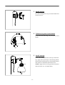
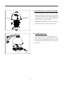
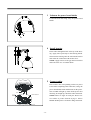
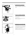
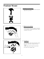
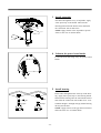
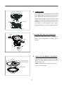
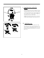
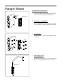
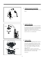
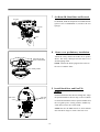
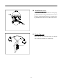
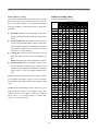
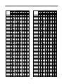
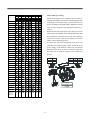
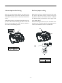
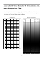
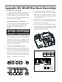
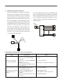
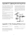
1
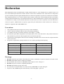
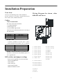
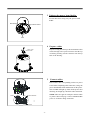
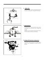
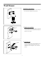
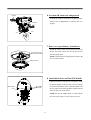
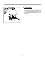
User Manual
DM870/DM880 High Speed Dome
Ⅰ
Before using the product, please read this manual carefully.
v2.0
CONTENTS
Welcome ............................................................................................................................................. 1
Declaration........................................................................................................................................... 2
Installation Preparation .......................................................................................................................... 3
Installation Type Guide .......................................................................................................................... 4
INSTALLATON TYPE GUIDE ............................................................................................................ 4
In-Ceiling Mount .................................................................................................................................. 5
Wall Mount .......................................................................................................................................... 9
Corner Mount .................................................................................................................................... 13
Pole Mount ........................................................................................................................................ 17
Pendant Mount ................................................................................................................................... 21
Parapet Mount ................................................................................................................................... 25
Operation .......................................................................................................................................... 29
A. Operation Instruction ................................................................................................................. 29
B. Menu Tree ................................................................................................................................ 30
C. Menu Operation ...................................................................................................................... 31
Selecting item ..................................................................................................................................... 31
1. System Setup............................................................................................................................. 32
2. Lens Parameters ........................................................................................................................ 36
3. Camera Parameters .................................................................................................................... 37
4. Pan/Tilt Parameters .................................................................................................................... 39
5. Function Setting ......................................................................................................................... 40
6. Privacy Masking ........................................................................................................................ 45
7. Alarm Setup .............................................................................................................................. 46
Appendix I: DIP Switch & Jumper Settings ........................................................................................... 47
Appendix II: Wire Diameter & Transmission Distance Comparison Chart ................................................ 53
Appendix III: RS485 Bus Basic Knowledge ......................................................................................... 54
Appendix IV: Lightning Proof & Surge Proof ....................................................................................... 56
Appendix V: The Cleaning Of Down Cover .......................................................................................... 56
Appendix VI: Trouble Shooting ............................................................................................................ 57
Appendix VII : Specification ................................................................................................................ 58
-61-
Welcome
Thank you for purchasing our HIGH SPEED DOME.
This series speed dome is newly upgraded with AMP connector for easier installation and black liner for discreet
surveillance. The powerful functions make it a state-of-the-art speed dome, and it will fulfill your wide range professional security surveillance need.
Features:
l
Backup Memory, parameters memory is designed to locate on the PCB board in the housing, settings will remain
when change PTZ module.
l
Auto runing, runs the assigned function automatically after a period of idling.
l
Timer runing,8 function schedules.
220 presets, 4 sequences with up to 32 presets each, 4 patterns with min. 180 seconds each, 4 pannings, 8
regions.
On screen compass and pan/tilt degrees indicator.
Up to 24 privacy masks.
With dome, preset, pattern, panning and region titles, the titles can be set to not display, display or display for a
period of time.
Color/Mono auto, manual or switch at a set time. (for day/night models).
With 4000V video, data, power lightning proof and surge proof.
Hi-accuracy motor drives with 0.1 degree preset accuracy, min. 0.1 degree moving without any vibration.
360 degrees continuous panning, 90 degree tilt with auto flipping.
Built in DSP camera, with auto focus, auto BLC, auto light control, auto white balance etc. functions.
Informative Chinese/English OSD menu, all the functions can be set via OSD menu.
l
l
l
l
l
l
l
l
l
l
-1-
Declaration
This equipment has been tested and found to comply with the limits for a Class A digital device, pursuant to part 15 of
FCC rules and European Union 89/336/EEC directive and its latest amended version. These limits are designed to
provide reasonable protection against harmful interference when the equipment is operated in a commercial environment.
This equipment generates, uses, and can radiate radio frequency energy and, if not installed and used in accordance
with the instruction manual, may cause harmful interference to radio communications. Operation of this equipment in
a residential area is likely to cause harmful interference in that case the user will be required to correct the interference
at his own expense. Modifications not expressly approved by the manufacturer could void the user’s authority to
operate the equipment under CE and FCC rules.
Precautions:
1.
Only qualified and experienced person can carry on this installation.
2.
3.
4.
Always conform to national and local safety codes during installation.
Use reliable tools only, poor quality tools may cause danger. e.g. ladder.
Do install the speed dome to appropriate environment (Please refer to the chart below). This product conforms to
IP66 standard as specified in “Housing Protection Classification (IP code)”.
Check the space and toughness of the site before installing. It should be able to bear 4 times the weight of the dome
and its accessories.
Keep all the original dome package materials in case of future repacking and transporting.
5.
6.
Model
Maximum Temp Range
Indoor
o
Outdoor
o
o
o
-10 C~+50 C
-40 C~+60 C
Humidity
<90%
<90%
Air Pressure
86~106KPa
86~106KPa
Power Supply
AC24V/1.25A, 50/60Hz
AC24V/2.5A, 50/60Hz
Warnings:
1.
2.
3.
4.
5.
6.
7.
DO NOT install this speed dome in hazardous places where combustible or explosive materials are stored or used.
DO NOT install indoor dome in outdoor environment.
This speed dome runs on 24V AC. DO NOT connect higher or lower voltage to it.
DO NOT turn power on before completing installation.
DO NOT disassemble any part of the items.
Use soft towel to clean the down cover when necessary. DO NOT use caustic detergent.
To protect CCD, avoid facing the camera directly to the strong light. e.g the sun.
-2-
Installation Preparation
Tools Lists:
Wiring Diagram for alarm, video
&RS485 and Power
You may need following tools for the installation:
Screws and nuts, screw driver, Small slotted screw
driver, Wire cutter, Ladder, Drill, Saw.
1
2
3
4
5
6
7
8
9
10
11
12
Cables:
Video Coaxial Cable
The video coaxial cable should be:
1) 75 Ohm impedance.
24
2) Solid copper wire.
3) 95% braided copper shield.
Check the max transmission distance referring to
the chart below.
International Gauge Transmission Distance( Max.)
RG 59/U
750ft (229m)
RG 6/U
1,000ft (305m)
RG 16/U
1,500ft (457m)
13
14
15
16
17
18
19
20
21
22
23
RS485 Cable
0. 56 mm (24 AW G) twi st ed pa ir ’s ma x imum transmission distances are as follows.
Baud Rate
2400bps
4800bps
9600bps
Transmission Distance (Max.)
5,906ft (1800m)
3,937ft (1200m)
2,625ft (800m)
NOTE: Use RS485 distributor if you need to transmit further. To learn more about RS485, please refer to appendix III.
DIP switches and jumpers settings
Please refer to appendix I to set the followings:
Protocol and Baud rate
Dome address
Video cable type
Alarm output method
RS485 termination resistor
1
2
3
4
5
6
7
8
Alarm Input1
Alarm Input2
Alarm Input3
Alarm Input4
Alarm Input5
Alarm Input6
Alarm Input7
Common Port
9
10
11
12
Alarm
Alarm
Alarm
Alarm
Output1
Output1
Output2
Output2
13 24V AC
14 Earth
15 24V AC
-3-
16
17
18
19
20
21
22
23
24
Video Output
Video Ground
RS485+
RS485Reserved
Reserved
Reserved
Reserved
RJ45
INSTALLATIONTYPE
INSTALLATON
TYPE
GUIDE
GUIDE
Installation
Type
Guide
Three main kinds of installation are available for high
speed dome:
1) In-ceiling Mount
2) Bracket Mount
There are 5 bracket options for bracket mount:
1) Wall Mount
2) Corner Mount
3) Pole Mount
4) Pendant Mount
5) Parapet Mount
Type
Surface Dome
Indoor Ceiling Dome
Indoor Dome
(excluding bracket)
Outdoor Dome
(excluding bracket)
Pendant Bracket
Wall Bracket
Corner Bracket
Pole Bracket
Parapet Backet
NOTE: Installation site should be able to withstand at
least 4 times the weight of the dome.
Weight (kg/lb)
2.20kg (4.85lb)
2.43kg (5.35lb)
2.93kg (6.45lb)
3.78kg (8.33lb)
1.53kg (3.37lb)
1.25kg (2.75lb)
1.90kg (4.19lb)
1.20kg (2.64lb)
6.50kg (14.33lb)
Bracket mount dome has indoor type and outdoor type. Comparing to indoor type, outdoor type has extra sun-shield
housing, temperature sensor and heater. Outdoor type conforms to IP66 standard.
WARNING: DO NOT install indoor dome in outdoor environment.
In-ceiling Mount
Bracket Mount
1. Wall Mount
2. Corner Mount
4. Pendant Mount
5. Parapet Mount
-4-
3. Pole Mount
In-Ceiling Mount
Installation requirements:
1. The thickness of the ceiling should be less than 42mm.
2. The ceiling should be able to bear 4 times the weight
of the speed dome.
3. Upper space should be at least 20cm high.
1 Draw a circle on the ceiling
Take the paper pattern(accessory) as a template to
draw a pattern on the ceiling. The paper pattern’s
diameter is 225mm.
2 Cut the circle off
2 25± 2
Use a saw or proper tool to cut off the circle.
NOTE: MAKE SURE the diameter of the circle is
225+2mm before cutting the circle off.
-5-
3 Unfasten the power board holder
Loosen the bolt to swing away the power board
holder.
Powe r Boa rd
Powe r Bo a rd Ho ld e r
Bo lt
4 Prepare cables
Prepare wiring and then put Power/RS485/Video
cables through water-proof connector and the top
of housing. Finally, turn the connector into the top
hole of the housing.
Water - proof
Connector
5
Insert cables into corresponding sockets on power
board. After completing cable connection, swing the
power board holder back and then turn on the power.
The red LED will light up. Turn off the power after
checking. If not light up, check the cable connection.
NOTE: There are signs for each port. connect cables
as picture showed in page 3. Please MAKE SURE
power is off before doing connection.
Bolt
Alarm
Connect cables
Video & RS485
Power
-6-
6 Adjust clips
Adjust the height of the three mounting clips.Swing
the three mounting clips to cling them to housing.
Mounting Clip
Ceiling Thickness
7 Install housing
Push housing into ceiling and let the clips stretch
out. Finally, screw the three clips to tighten the
housing.
NOTE: Use even strength to adjust the three clips,
or it may distort the shape of the housing.
Moun ting Clip
M ounting Clip
M ounting Clip
SPONGE
8 Set dome ID, baud rate and protocol
Set dome ID, baud rate and protocol via DIP switches
(please refer to APPENDIX I ). Remove the two
sponges.
SPONGE
SW1
SW1
SW2
SW2
-7-
9 Install black liner and Pan/Tilt Module
Guide Pole
AMP Socket
Push the black liner into the two locking tabs. Align
the pan/tilt module to the two clips, red to red, black
to black and match the holes in pan/tilt module and
the two guide poles.Gently push the module upward
until you hear two click sound.
Red Lable
Red Clip
NOTE: Be sure the AMP sockets are clean without
any dust. DO NOT forget to remove the lens cover.
P/T Module
Tab
Tab
Black Liner
10 Install down cover
Fix the safety chain on housing. The safety chain
prevents the down cover dropping down. Match the
clasps and mounting holes then turn the down cover
frame anti-clockwise.
NOTE:
l
Let the safety chain inside the arc groove of
the down cover, otherwise it may scratch the lens.
l
If you found difficult to fit in the down cover,
try readjusting the three clips.
Mo unting Ho le
Sa fe ty C hain
C la sp
-8-
Wall Mount
Installation requirements:
The wall mounting surface must be firm enough to
bear 4 times the weight of the speed dome.
1 Mark screws positions
84
140
Take the bracket base as the template to mark the
screws positions on wall. Drill the holes and put expansion screws inside.
2 Install bracket
M8
Put Power/RS485/Video cables through the cavity
of bracket, and then install bracket on the wall.
NOTE: Put cables through the wall or aside the
bracket.
-9-
3 Unfasten the power board holder
Loosen the bolt and swing away the power board
holder.
Bolt
4 Install housing
Insert cables through the hole at the top of the housing
Apply water-proof tape to the housing thread. Then
turn the housing onto the wall mount bracket and
retain the connection with an M4 screw.
NOTE: Apply silicone to the gap between bracket
and wall in the case of outdoor dome.
M4
Tape
5 Connect cables
Insert cables into corresponding sockets on power
board. After completing cable connection, swing the
power board holder back and then turn on the power.
The red LED will light up. Turn off the power after
checking. If not light up, check the cable
connection.
NOTE: There are signs for each port. Please connect cables as picture showed in page 3. Please
MAKE SURE power is off before doing connection.
Bolt
Video& RS485
Power
-10-
6 Set dome ID, baud rate and protocol
SPONGE
Set dome ID, baud rate and protocol via DIP switches
(please refer to APPENDIX I ). Remove the two
SPONGE
SW1
SW1
sponges .
SW2
SW2
7 Down cover preliminary installation
Attach the safety chain with an M3 nut as picture
shows. The safety chain prevents the down cover
from dropping down.
NOTE: Connect the heater plug into the socket in the
case of outdoor dome.
Connect the two
ports of the heater
M3 Nut
Safety Chain
8 Install black liner and Pan/Tilt Module
AMP Socket
Push the black liner into the two locking tabs. Align
the pan/tilt module to the two clips, red to red, black
to black and match the holes in pan/tilt module and
the two guide poles.Gently push the module upward
until you hear two click sound.
Red Lable
Red Clip
NOTE: Be sure the AMP sockets are clean without
dust. DO NOT forget to remove the lens cover.
-11-
9 Install down cover
Loosen the two M4 screws on down cover ring.
Apply lubricant to the O-ring to make down cover
easier to slip in. Push upward the down cover into
the housing and then fasten down cover with two
M4 screws.
M4
M4
Lube
-12-
Corner Mount
Installation requirements:
The corner mounting surface must be firm enough to
bear 4 times the weight of the speed dome.
1 Mark screws positions
Take the bracket base as the template to mark the
screws positions on the wall. Drill the holes and put
expansion screws inside.
2 Install base
Put Power/RS485/Video cables through the hole of
corner base and use M8 nuts to fasten corner base
on the mounting surface.
NOTE: Put cables through the wall or aside the
corner base.
-13-
3 Install bracket
Put cables through the cavity of bracket and fasten
bracket on base.
4 Unfasten the power board holder
Loosen the bolt and swing away the power board
holder.
Bolt
5 Install housing
Insert cables through the hole at the top of the housing Apply water-proof tape to the housing thread.
Then turn the housing onto the wall mount bracket
and retain the connection with an M4 screw.
NOTE: Apply silicone to the gap between bracket
and wall in the case of outdoor dome.
M4
Tape
-14-
6 Connect cables
Insert cables into corresponding sockets on power
board. After completing cable connection, swing the
power board holder back and then turn on the power.
The red LED will light up. Turn off the power after
checking. If not light up, check the cable connection.
Bolt
Video & RS485
NOTE: There are signs for each port. Please connect cables as picture showed in page 3. Please
MAKE SURE power is off before doing connection.
Power
7 Set dome ID, baud rate and protocol
SPONGE
Set dome ID, baud rate and protocol via DIP switches
(please refer to APPENDIX I ). Remove the two
sponges .
SPONGE
SW1
SW1
SW2
SW2
8 Down cover preliminary installation
Attach the safety chain with an M3 screw as
picture shows. The safety chain prevents the
down cover from dropping down.
NOTE:Connect the heater plug into the socket in
the case of outdoor dome.
Connect the two
ports of the heater
M3 Nut
Safety Chain
-15-
9 Install black liner and Pan/Tilt Module
Push the black liner into the two locking tabs. Align
the pan/tilt module to the two clips, red to red, black
to black and match the holes in pan/tilt module and
Red Lable
Red Clip
AMP Socket
the two guide poles. Gently push the module upward until you hear two click sound.
NOTE: Be sure the AMP sockets are clean without
dust. DO NOT forget to remove the lens cover.
10 Install down cover
Loosen the two M4 screws on down cover ring.
Apply lubricant to the O-ring to make down cover
easier to slip in. Push upward the down cover into
the housing and then fasten down cover with two
M4 screws.
M4
Lube
-16-
Pole Mount
Installation requirements:
The outside diameter of the pole must be in the range
of 130-150mm (5.12 ~6 inches).
1 Install base
Mount the pole adaptor to the pole with two mounting clamps. Put Power/RS485/Video cables through
the central hole of the bracket base, and then fix it
around the pole.
2 Install wall mount bracket
M8
Put cables through the cavity of wall mount bracket
and fasten it on base.
M4
-17-
3 Unfasten the power board holder
Loosen the bolt and swing away the power board
holder.
Bolt
4 Install housing
Insert cables through the hole at the top of the housing Apply water-proof tape to the housing thread.
Then turn the housing onto the wall mount bracket
and retain the connection with an M4 screw.
NOTE: Apply silicone to the gap between bracket
and wall in the case of outdoor dome.
M4
Tape
5 Connect cables
Insert cables into corresponding sockets on power
board. After completing cable connection, swing the
power board holder back and then turn on the power.
The red LED will light up. Turn off the power after
checking. If not light up, check the cable connection.
NOTE: There are signs for each port. Please connect cables as picture showed in page 3. Please
MAKE SURE power is off before doing connection.
Bolt
Video & RS485
Power
-18-
6 Set dome ID, baud rate and protocol
SPONGE
Set dome ID, baud rate and protocol via DIP switches
(please refer to APPENDIX I ). Remove the two
SPONGE
SW1
sponges.
SW2
SW2
SW1
7 Down cover preliminary installation
Attach the safety chain with an M3 nut as picture
shows. The safety chain prevents the down cover
from dropping down.
Connect the two
ports of the heater
NOTE:Connect the heater plug into the socket in
the case of outdoor dome.
M3 Nut
Safety Chain
8 Install black liner and Pan/Tilt Module
AMP Socket
Push the black liner into the two locking tabs. Align
the pan/tilt module to the two clips, red to red, black
to black and match the holes in pan/tilt module and
the two guide poles. Gently push the module upward until you hear two click sound.
Red Lable
Red Clip
NOTE: Be sure the AMP sockets are clean without
dust. DO NOT forget to remove the lens cover.
-19-
9 Install down cover
Loosen the two M4 screws on down cover ring.
Apply lubricant to the O-ring to make down cover
easier to slip in. Push upward the down cover into
the housing and then fasten down cover with two
M4 screws.
M4
Lube
-20-
Pendant Mount
Installation requirements:
The ceiling must be firm enough to bear 4 times the
weight of the speed dome.
1 Mark screws positions
Take the bracket base as the template to mark the
screws positions on ceiling. Drill the holes and put
expansion screws inside.
2 Install base
Put Power/RS485/Video cables through the central
hole of the bracket base, and then fix it on the
ceiling.
NOTE: Apply silicone along the top of bracket
base in the case of outdoor dome.
Silicone
-21-
3 Install suspender
Put cables through the cavity of suspender. Apply
water-proof tape to the thread. Then turn the
thread pipe head into the bracket base and fasten
the connection with an M4 screw.
M4
NOTE: Apply silicone to the suspender as picture
Tape
shows in the case of outdoor dome.
T h re a d
S i lic o n e
4 Unfasten the power board holder
Loosen the bolt and swing away the power board
holder.
Bolt
5 Install housing
Insert cables through the hole at the top of the housing Apply water-proof tape to the housing thread.
Then turn the housing onto the wall mount bracket
and retain the connection with an M4 screw. If installation height is not high enough, mount housing
directly into the base.
NOTE: Apply silicone to the gap between bracket
and wall in the case of outdoor dome.
M4
M4
Tape
Tape
-22-
6 Connect cables
Insert cables into corresponding sockets on power
board. After completing cable connection, swing the
power board holder back and then turn on the power.
The red LED will light up. Turn off the power after
checking. If not light up, check the cable connection.
Bolt
Video& RS485
NOTE: There are signs for each port. Please connect cables as picture showed in page 3. Please
MAKE SURE power is off before doing connection.
Power
7 Set dome ID, baud rate and protocol
SPONGE
Set dome ID, baud rate and protocol via DIP switches
(please refer to APPENDIX I ). Remove the two
sponges.
SPONGE
SW1
SW1
SW2
SW2
8
Down cover preliminary installation
Attach the safety chain with an M3 nut as picture
shows. The safety chain prevents the down cover
from dropping down.
NOTE:Connect the heater plug into the socket in
the case of outdoor dome.
Connect the two
ports of the heater
M3 Nut
Safety Chain
-23-
9 Install black liner and Pan/Tilt
Module.
Push the black liner into the two locking tabs. Align
the pan/tilt module to the two clips, red to red, black
Red Lable
Red Clip
AMP Socket
to black and match the holes in pan/tilt module and
the two guide poles. Gently push the module upward until you hear two click sound.
NOTE: BE SURE the AMP sockets are clean without dust. DO NOT forget to remove the lens cover.
10 Install down cover
Loosen the two M4 screws on down cover ring.
Apply lubricant to the O-ring to make down cover
easier to slip in. Push upward the down cover into
the housing and then fasten down cover with two
M4 screws.
M4
M4
Lube
Lube
-24-
Parapet Mount
Installation Requirements:
The wall mounting surface must be firm enough to
bear 4 times the weight of the speed dome.
Bracket Base
1
Mark Screws Positions
Take the bracket base as the template to mark the
screws positions on the wall, and then drill the holes.
2 Install Base
Fix the bracket base on the wall with the M8 expansive screws.
M8
3 Install Pipe Arm
Put the cables through the two trays of the base and
pipe arm, and plug the pipe arm into two trays
Pipe Arm
-25-
4 Unfasten the power board holder
Loosen the bolt and swing away the power board
holder.
Bolt
5 Install the Housing
Insert cables through the hole at the top of the housing Apply water-proof tape to the housing thread.
Then turn the housing onto the wall mount bracket
and retain the connection with an M4 screw.
NOTE: Apply silicone to the gap between bracket
and wall in the case of outdoor dome.
Silicone
M4
6 Connect cables
Insert cables into corresponding sockets on power
board. After completing cable connection, swing
the power board holder back and then turn on the
power. The red LED will light up. Turn off the
power after checking. If not light up, check the
cable connection.
NOTE: There are signs for each port. Please
connect cables as picture showed in page 3. Please
MAKE SURE power is off before doing
connection.
Bolt
Video & R S485
Power
-26-
7 Set Dome ID, Baud Rate and Protocol
SPONGE
Set dome ID, baud rate and protocol via DIP switches
(please refer to APPENDIX I ). Remove the two
sponges.
SPONGE
S W1
SW1
SW2
SW2
8
Down cover preliminary installation.
Attach the safety chain with an M3 nut as picture
shows. The safety chain prevents the down cover
from dropping down.
NOTE: Connect the heater plug into the socket in
the case of outdoor dome.
Connect the two
ports of the heater
M3 Nut
Safety Chain
9 Install black liner and Pan/Tilt
Module.
AMP Socket
Push the black liner into the two locking tabs. Align
the pan/tilt module to the two clips, red to red, black
to black and match the holes in pan/tilt module and
the two guide poles. Gently push the module upward until you hear two click sound.
Red Lable
Red Clip
NOTE: Be sure the AMP sockets are clean without
dust. DO NOT forget to remove the lens cover.
-27-
10 Install down cover.
Loosen the two M4 screw on down cover ring. ApM4
ply lubricant to the O-ring to make down cover easier
to slip in. Push upward the down cover into the housing and then fasten down cover with two M4 screws.
Lube
11 Fix the Pipe Arm
Rotate the pipe arm to the proper place, fix the pipe
arm to the base with the two metal hoops.
Metal Hoop
-28-
Operation
A. Operation Instruction
Accessing the System Menu
Two methods are available for carrying out the opera-
l
Access the dome’s main system menu on your
tion by the system controller.
monitor by calling preset 95 once or calling preset
1.
1 twice within 5 seconds.
2.
Press the combined hot keys to operate different
functions. Please refer to the system controller
Note: The way to call a preset may vary among key-
manual for the detailed commands.
Access the OSD menu and operate according to
boards with different manufactures. Please read
those manuals to learn keyboard operation.
l
the following instruction.
When there is password protection, user needs to
input the correct 6-bit password to access to the
Initial Information
OSD menu. (Default password is 000000).
l
When you turn on the power for the dome or restart it
, the self-test function is begun, and as it finishes,the
down to select number (0-9), move the joystick
left or right to choose password digit. If the input
password is wrong, the password input window
will close.
Note: You still can control the dome with a wrong
password, but can not access to the OSD menu.
initial information below will be displayed on the
screen . Meanwhile this information is disappeared
after receiving the first effective command.
Dome S/N
Dome ID
Baudrate
Protocol
Model
Version
Fan Speed
Temp
H-Check
V-Check
Camera
Ready
To input the password, move the joystick up or
:0000000000000000
:0001<Hard>
:4800
:FACTORY
:EP-908
:1.00
:6500
:037C
:Pass
:Pass
:Pass
System Menu
====================================
1.System Information
2.Lens Parameters
3.Camera Parameters
4.Pan/Tilt Parameters
5.Auto Running Setup
6.Timer Running Setup
7.Privacy Masking
8.Alarm Setup
0.Exit
Dome S/N: The dome’s serial number
Dome ID: The dome ID address set by DIP switch
or keyboard.
Baudrate: Baud rate for dome control bus.
Protocol: The dome’s controlling protocol.
(please refer to appendix I for more details)
Model:
The dome model number.
Fan Speed: The speed of current running fan
caculated by rounds per minute.
Temp:
The dome inside tempertature.
Unit C or F
The opened menu will disappear automatically without
receiving any operation command in 1 minute. All the
settings will be saved automatically to protect against
power cuts.
-29-
System Setup
====================================
1.Dome Information
2.Display Configuration
3.Change Password
4.Language Select
5.Factory Default
6.System Restart
7.About
8.Back
0.Exit
B. Menu Tree
Lens Parameters
====================================
1.Zooming Speed
:High/low
2.Max Digital Zoom :Off
3.Focus Limit
:1cm
4.Vibration Correction: Off
5.Iris ALC Value
:000
6.Iris PLC Value
:000
7.Auto Recovery
8.Day/Night Mode
9.Back
0.Exit
Main Menu
====================================
1.System Setup
2.Lens Parameters
3.Camera Parameters
4.Pan/Tilt Parameters
5.Function Setting
6.Privacy Masking
7.Alarms Setup
0.Exit
Camera Parameters
====================================
1.Picture Freeze
:OFF
2.Line Lock Phase
:OFF
3.Exposure Mode
4.White Balance
5.Backlight Mode
6.Back
0.Exit
Pan/Tilt Parameters
====================================
1.Auto Stop Timer
:OFF
2.Speed Magnifier
:x01
3.Proportional PT
:On
4.Set North Direction
5.Max Vertical Angle
:090
5.Back
0.Exit
Function Setting
====================================
1.Presets Setup
2.Sequence Setup
3.Pattern Setup
4.Autoscan Setup
5.Regions Setup
6.Time Action
7.Idle Action
8.Back
0.Exit
Privacy Masking
====================================
1.Mask Number
:001
2.Setup New Mask
3.Activate
:OFF
4.Show Next Mask
5.Delete Current Mask
6.Back
0.Exit
Alarms Setup
====================================
1.Input Channel
:001
2.Alarm Action
:OFF
3.Input Mode
:NC
4.Alarm Linkage
:OFF
5.Alarm Output
:OFF
6.Reset Delay
:OFF
7.Arm Time
:00:00
8.DisArm Time
:00:00
9.Back
0.Exit
-30-
C. Menu Operation
Main menu à System Setupà Change Password
Selecting item
l
l
In the main menu, the cursor flashes on the left,
tilt the joystick up or down to move the cursor to
the desired setting item. Move the joystick to right
to select the item.
Select an item to ① access its sub-menu or ② run
a specific function or ③ change its value or ④
edit its title.
Enter New Password
====================================
Input [******]
Back
4. Input the old password and new password, Default
Changing values
password is 000000. Move the joystick to left or right
to different position; Move it up or down to change a
Move the joystick up or down to change the value, move
the joystick tothe left to save the setting and then exit.
number. After inputting a new password,move the
In the case of more than one value, move the joystick to
cursor to leftmost index position.
the left or right to select different position, and then
5. Select “3. Confirm” to confirm the new password.
System will indicate “Old Password error” or “ Pwd
Modify Success”.
move it up or down to change value, finally move the
joystick to the leftmost to save the setting and then
exit.
Note: To increase the value of the selected field, hold
the joystick on up or down position for more than 10
seconds.
Editing titles
Access Dome Title Edit Menu following the path:
System setup → Dome Information → Title →
Input
For example: In order to change the password, please
follow these steps.
1. Press 9 + 5 nemeric buttons and PRESET button, or
press the 1 numeric button and PRESET button twice
within five seconds to enter main
Edit Dome Title
===================================
Input[A
]
Back
Main Menu
====================================
1.System Setup
2.Lens Parameters
3.Camera Parameters
4.Pan/Tilt Parameters
5.Function Setting
6.Privacy Masking
7.Alarms Setup
0.Exit
===================================
Uppercase (Zoom Shift)
Move the cursor to left or right to select a character,
move it down to edit the blinking character. Zoom In/
out to switch character groups:
2. Move the joystick down to make the cursor point to
System Information then move the joystick to the right
to select it.
Number [0 1 2 3 4 5 6 7 8 9 ]
Capital [A B C ]
System Setup
====================================
1.Dome Information
2.Display Configuration
3.Change Password
4.Language Select
5.Factory Default
6.System Restart
7.About
8.Back
0.Exit
Lowercast
[a b c ]
Sign [ / + - ( ) & % # ! $ ]
Special char [ á í ó w é ]
Move the joystick to desired character,and then move
it up to select or down to cancel.
Note: Pressthe 1 numeric button and PRESET button
to switch between Modify and Insert editting method.
3. Move the joystick down to select Change Password
Note: Here-in-after menu paths are written in the
following format:
-31-
1. System Setup
2.Dome Title: There are two titles. Each one has a maxi-
Main menu à System Setup
mum of 20 characters consisting of English(Chinese),
System Setup
====================================
1.Dome Information
2.Display Configuration
3.Change Password
4.Language Select
5.Factory Default
6.System Restart
7.About
8.Back
0.Exit
numbers,and special characters .
The name is useful to identify which dome it is. You can
edit dome title refer to page 36.
Edit Dome Title
===================================
1.1 Dome Information
Input[A
Back
]
Main menu à System Setup à Dome Information
===================================
Uppercase (Zoom Shift)
Dome Information
====================================
1.Dome ID
:001
2.Title
:A
3.Title
: B
4.Broadcast ADD
:2 5 5
5.System Time
:00:00
6.System Date
:00-00-00
7.Auto Restart
:00:00
8.Back
0.Exit
3.Dome Title: Sets the second 10 characters of the title.
Repeat the step 2 to complete the Title setting.
4. Broadcast ADD: It sets broadcast.
ID number (001~255). The ID number should be different from any other dome, default setting is 255.
When a command is sent to broadcast ID, all the domes
connected to the control bus accept the command. Please
refer to page 48 to get information about ID setting.
1. Dome ID: Dome ID shows the current dome’s
ID number. Each dome has its unique ID ranging from
001 to 255 (255 is default broadcast ID ). The Dome
ID can be set only when DIP switch is in Programmable ID mode.
5.System Time: Set the system time in order to show
the time on the screen and enable timer scheduled
functions. Display format: hour : min
1.1 Move the cursor to select Dome ID ,and then move
it to right. The following picture will be displayed on the
screen.
6.System Date: Set the system date in order to show
the date of displaying on the screen. The default format
is DD-MM-YY.
Note: The display format of system date cannot be
changed, users can change the date itself only.
Enter S/N: 6161310854
====================================
1.Input[0000000000]
2.Back
====================================
Numeric (Zoom Shift)
1.2 Move the joystick to select input,and then enter
number in accordance with above S/N number.
7.Auto Restart: Set the auto restart time in order to
make the dome restart at a perticular time.
Note: When auto restart time is 00:00, this function is in
the default state, which is closed.
1.3 Move the joystick up or down to change the value
and then move it to left to save the setting.
8.Back: Return to previvous menu.
-32-
1.2 Display Configuration
Main Menuà System Setup à Display Configuration
Zoom Position (ON, OFF, 2s-60s): Displays time of
the zoom times.
Display Configuration
====================================
1.Title Display
2.Other Display
3.Back
0.Exit
Direction Disp (ON, OFF, 2s-60s): Displays time of
camera pointing direction.
Alarm Indicator (ON/OFF): Displays the alarm state
information.
System Clock (ON/OFF) :Display the system time.
Select BACK to return to the previous menu.
Title Display
====================================
1.Dome Title
:o f f
2.Preset Title
:o f f
3.Pattern Title
:o f f
4.Autoscan Title
:o f f
5.Regions Title
:o f f
6.Back
0.Exit
The following settings are available for each one:
OFF: This function is disabled.
ON: This function is enabled.
2s-60s: The function is displayed within a range of
two seconds to sixty seconds after activation.
1.2.1 Title Display
This allows you to program how titles are display on
the monitor.The following titles can be set:
Dome Title (ON,OFF,2s-60s): Displays the dome
title.
Presets Title (ON, OFF, 2s-60s) :Displays preset
title when calling up the preset.
Pattern Title (ON, OFF, 2s-60s):Shows the pattern
title when running the pattern.
Autoscan Title (ON, OFF, 2s-60s) :Shows the title
during automatic scanning operation.
Regions Title (ON, OFF, 2s-60s) :Displays the region
title for the region mode settings.
l
Information Text Position
Fan indicator
Preset/Pattern/
sequence/autoscan
Title
Alarm 1 2 3 4 5 6 7
134/074
1 2
2X
16:25:06
Time
Alarm output channel
Zoom times
Alarm input channel
Vertical tilt degree
Horizontal pan degree
The following settings are available for each title:
OFF: The title is not displayed when enabled.
ON: The title is displayed after activation.
2s-60s: The title is displayed within a range of two
seconds to sixty seconds after activation.
Dome title
1.2.2 Other Display
Other Display
====================================
1.Zoom Position
:o f f
2.Direction Disp
:o f f
3.Alarm Indicator :o f f
4.System Clock
: off
5.Back
0.Exit
-33-
1.3 Change Password
7. If the old password is input worngly,the following
Main menu à System Setupà Change Password
picture is on the screen.The screen menu is cleared
automatically.
1.Select “Change Password”,and then move the joystick
lever to right.The following picture will be displayed on
Error Password!
the screen.
Enter New Password
====================================
Input [******]
Back
Note:If the default password is changed ,the password
protection is activated.It is requirement to enter the password whenever you want to access the OSD menu.
1.4 Language Select
2 Input the new password,firstly move the joystick lever to up or down to change the value, and then move it
to left or right to a different position.
Main menu à System Setupà Language Select
3 Select “Back”,and move the joystick lever to left.
The following picture will be displayed on the screen.
Language Select
====================================
1.Language:
English
2.Character List
3.Back
0.Exit
Confirm Password
====================================
Input [******]
Back
There are five languages available: English,Chinese,
Espanol, Italtano,Deutsch.
4 Enter the new password again in the same way ,and
then move the joystick lever to left.
1.5 Factory Default
5 Select “Back”, the following pictures will pop out the
screen if the password is input correctly.
Main menu à System Setupà Factory Default
System Setup
====================================
1.Dome Information
2.Display Configuration
3.Change Password
4.Language Select
5.Factory Default
6.System Restart
7.About
8.Back
0.Exit
Password change succeed!
Select Factory Default to restore factory default
settings. System will request password to set it. Factory
default will not change dome ID.
6.If the password is not input correctly,the following
picture will be displayed. Thus it is necessary to enter
again in the same way, otherwise you can not access to
OSD menu.
Factory Restoring...
Password not match!
-34-
List of Default Setting
l
Select ABOUT to display information.
l
Select BACK to return to the previous menu.
Zooming Speed
HIGH
White Balance
Auto
Digital Zoom
x10
Focus M in Limit
30CM
Joystick Auto
Both
Idle Time
30S
Camera ID:0001(HARD)
Auto Focus
5S
Auto action
Off
Baud Rate:9600bps
Protocol:Factory
Auto Iris
5S
Alarm M ode
M anual
Model: EP-908
Iris ALC
084
Set Alarm
Armoff
Temperature:+34C/+93F
Iris PLC
016
Input State
NC
Version:2003,2005
Day Night Mode
Auto
Run Function
Off
Any command to exit
Sensitivity
1/1.5
Alarm Output
Off
This menu screen can not be changed or altered.It is
Preset Freeze
Off
Reset Delay
20S
provided for information purposes only.
Camera S/N:1234567890
NOTE: The menu screen is cleared automatically as
any command is carried out.
1.6 System Restart
Main menu à System Setupà System Restart
System Setup
====================================
1.Dome Information
2.Display Configuration
3.Change Password
4.Language Select
5.Factory Default
6.System Restart
7.About
8.Back
0.Exit
Move the joystick lever to select System Restart,the
following picture will display on the screen.Settings
will not change after restarting.
System Restart...
1.7 About
Main menu à System Setupà About
System Setup
====================================
1.Dome Information
2.Display Configuration
3.Change Password
4.Language Select
5.Factory Default
6.System Restart
7.About
8.Back
0.Exit
-35-
2. Lens Parameters
Main menu àLens Parameters
2.6 Iris PLC Value( Some camera only)
This sets the iris peak level control value. The value
Lens Parameters
====================================
1.Zooming Speed
:High
2.Max Digital Zoom :Off
3.Focus Limit
:1cm
4.Vibration Correction: Off
5.Iris ALC Value
:000
6.Iris PLC Value
:000
7.Auto Recovery
8.Day/Night Mode
9.Back
0.Exit
ranges from 000 to 127.Default value: 23X color/
mono camera: 016 (different camera has different
PLC default value)
Note: Changing default value is strongly NOT
recommended.
2.1 Zooming Speed
2.7 Auto Recovery
Auto Recovery
====================================
To set the zoom speed level to High or Low.
1.Joystick Recover: ALL
2.A/F Recover Time:005
3.A/I Recover Time:005
4.Back
0.Exit
2.2 Max Digital Zoom
Max Digital zoom magnifies the picture by duplicating
pixels. The picture is enlarged but the resolution
remains the same. This menu item sets max. digital
zoom magnification times.
Turn off digital zoom
OFF :
X1-~ X10 : Max. digital zoom times
This lets you set whether operation returns to automatic focus and automatic iris if manual focus and
manual iris are being used.The options are as follows:
All : Both auto focus and auto iris are restored.
(default setting)
Focus : Auto focus is restored only.
Different camera has different Max. digital zoom
times.
2.3 Focus Limit
Iris:
auto iris is restored only.
None : Neither is restored or not.
The focus limit sets the minimum distance between
the object and the camera. Focus is not achieved if the
distance is less than the current setting. Eg: This
function can prevent the camera from focusing
raindrops and water vapor of the down cover in the
rain day.The following values for focus limit are
available:1cm.10cm,30cm,100cm
2.8 Day/Night Mode
Day/Night Mode
====================================
1.Day/Night Mode: AUTO
2.Day Start Time: 00:00
3.Nite Start Time:00:00
4.Back
0.Exit
2.4 Vibration Correction( Some camera only)
This prevents the image from intensively vibration as
vehicles frequently passed.
The Day/Night mode automatically switches between
color and monochrome mode in accordance with the
environment illumination. Color mode is suitable to
work in daytime,while mono mode is suitable to work
at night in low illumination environment but the video
is black and white.
Auto: The dome will automatically change modes in
accordance with the environment illumination.
Day: The dome is always in colorful mode.
Night: The dome is always in monochrome mode.
Time: Set schedule for mode change.
Note: You need to set exposure mode to Auto in order
to get Auto Day/Night mode.
2.5 Iris ALC Value( Some camera only)
This sets the iris average level control value. The value
ranges from 000 to 255.
Default value: 22X color camera: 066, 23X color/
mono camera: 084 (different camera has different
ALC default value)
Note: Changing default value is strongly NOT
recommended.
-36-
3. Camera Parameters
Main menu à Camera Parameters
Only one of settings for Shutter, Iris and AGC will
take effect
Camera Parameters
====================================
1.Picture Freeze
:OFF
2.Line Lock Phase
:OFF
3.Exposure Mode
4.White Balance
5.Backlight Mode
6.Back
0.Exit
Mode
Shutter
Iris
AGC
Auto
N/A
N/A
N/A
Shutter
1/1.5、
1/3、
1/6、
1/12、
1/25、
1/50、
1/100、
1/150、
1/250、
1/500、
1/1000、
1/2000、
1/4000、
1/10000、
1/30000
N/A
N/A
F1.6、
F2.2、
F3.2、
F4.4、
F6.4、
F8.8、
F12、
F17、
F24、
F34
N/A
N/A
0dB、
6dB、
12dB、
18dB、
24dB、
30dB
3.1 Picture Freeze
There are two selections: ON and OFF.
ON: The current image is frozen.
OFF: This function is void.
Note: This feature is to reduce useless data traffic in
web application and save storage space for DVR.
3.2 Line Lock Phase
The following selections are available:
OFF:This function is void.
001-360: It lets you choose the suitable phase to obtain
synchronous video.
Iris
N/A
3.3 Exposure Mode
Exposure Mode
====================================
1.Exposure Mode: AUTO
2.Exposure Level: N/A
3.Slow Shutter:
1/1.5
4.Back
0.Exit
AGC
Set the exposure mode. The value options are: Auto,
Shutter, Iris and AGC.
Shutter:
Set Shutter speed in priority, available: settings
are 1/1.5, 1/3, 1/6, 1/12, 1/25, 1/100, 1/150, 1/
250, 1/500, 1/1000, 1/2000, 1/4000, 1/10000, 1/
30000
Iris:
Set Iris in priority. Values are: F1.6, F2.2, F3.2,
F4.4, F6.4, F8.8, F12, F17, F24, F34
AGC:
Set Auto gain control in priority. Values are: 0dB,
6dB,12dB,18dB,24dB,30dB. Higher dB value makes
image brighter.
N/A
3.4 White Balance
White Balance
====================================
1.White Balance: AUTO
2.User Defined R: 000
3.User Defined B: 000
4.Back
0.Exit
White balance: The adjustment is carried out in two
ways: Auto or User
User Defined R: It sets the white balance R value,
ranging from 000 to 255.The higher the number, the
stronger is the red component.
User Defined B:It sets the white balance B value,
ranging from 000 to 255.The higher the number, the
stronger is the blue component.
Note: Day/Night auto mode and Sensitivity Up will be
void if Exposure mode is not Auto mode.
-37-
3.5 Backlight Mode
Backlight Mode
====================================
1.Backlight Mode: OFF
2.Backlight Value: N/A
3.Back
0.Exit
This sets backlight compensation.
If the backlight is bright, the objects in the center of the
picture may be dark. The dome can automatically adjust
the brightness of the whole image according to the brightness of center point.
Therefore backlight compensation can increase the
brightness of the objects in the center.
OFF: This function is not carried out.
Normal: Standard BLC mode.
WDR: Wide Dynamic Rage mode.
NOTE: This function is used for the cameras supporting WDR
As the backlight mode is setting in the standard
Normal or WDR mode, different backlight compensation grade can be set as follows:
000 This function is not carried out.
001-255 Choose different backlight compensation
grade. The higher the number,the brighter
is the image.
Mode
Normal
WDR
Off
N/A
N/A
Normal
000-255
N/A
WDR
N/A
000-127
-38-
4. Pan/Tilt Parameters
range of vertical observation, from 75 degrees to 95
Main menuà Pan/Tilt Parameters
degrees, which is the maximum one.
Pan/Tilt Parameters
====================================
1.Auto Stop Timer
:OFF
2.Speed Magnifier
:x01
3.Proportional PT
:On
4.Set North Direction
5.Back
0.Exit
4.5 Set North Direction
User can set dome’s orientation on screen by using
joystick to position north.Pan degree is the relative
degree to a specific direction. That direction is called
NORTH.
4.1 Auto Stop Timer
Note: Not restrict to geographical north.
For some particular protocols, the dome does not stop
Dome title
moving even if no operation comes form the controller.
Preset/Pattern/
But this function lets the dome stop at a fixed time you
sequence/autoscan
set in advance.
OFF: This function is not carried out. (default
Title
1 2
Alarm 1 2 3 4 5 6 7
setting)
134/074
2X
001~100: After value x 50ms the dome will automatically stop moving. For example: 003 means the
16:25:06
Time
Alarm output channel
Zoom times
Alarm input channel
Vertical tilt degree
Horizontal pan degree
dome will automatically stop moving after 150ms.
4.2 Speed Magnifier
Fan indicator
Some protocols’ controlling speed is either faster or
slower, however it can be adjusted via Speed
magnifier. The selections are as follows:
Horizontal 0~360
330
N
X1: Original speed (default setting)
30
Vertical 0~90
0
90
NE
60
↑ 2 ~ ↑ 32: Times faster than original speed.
E
W
↓ 2 ~ ↓ 32: Times slower than original speed.
120
4.3 Proportional PT
S
The dome moves at a speed of certain degrees per
second. Objects on screen move much faster in telescope than in widescope, even undesirable too faster
in some case. This function decreases the dome
For example
Move TO The Object
Call Preset 1 To Confirm
movement speed while zooming in.
ON :
Enable the function (default setting)
OFF:
Disable the function
90
0
4.4 Max Vertical Angle
For this setup, you can set the max tilt degree of
the speed dome. This function is for changing the
l
-39-
Move to a position and call preset 1 to confirm.
5. Function Setting
Main menuà Function Setting
Call Preset 1 Save
Call Preset 2 cancel
Function Setting
====================================
1.Presets Setup
2.Sequence Setup
3.Pattern Setup
4.Autoscan Setup
5.Regions Setup
6.Time Action
7.Idle Action
8.Back
0.Exit
Move to the desired position and zoom to a suitable
level, call preset 1 to save the current preset, call
5.1 Preset Setup
preset 2 to cancel.
Main menuà Function Settingà Preset setup
4.Show Next Preset:It moves to the next position
Preset
====================================
1.Preset Number
:001
2.Title
3.Set New Preset
4.Show Next Preset
5.Delete Current
6.Back
0.Exit
according to the numerical order.
5. Delete Current: The current preset is deleted as
you tilt the joystick lever to select it.The following
picture will display on the screen.
This function allows memorization of the angle, zoom
and focus settings for the camera if any location is
monitored.
l
Up to 220 preset positions can be stored.
l
You can press the numeric button and the PRESET button of the system controller to access each preset position set in advance.
Deleting.....
5.2 Sequence Setup
1.Preset Number:It sets the preset number,ranging
from 001 to 255.
Main menuà Function Settingà Sequence setup
Sequence
====================================
1.Sequence Number :001
2.Default Dwell
:003
3.Edit Sequence
4.Run Only Once
5.Run continuously
6.Delete Current
7.Back
0.Exit
2.Title: It sets the name for the preset position,which
can be displayed on the screen.
Preset Title Edit
====================================
1.Input: [
]
2.Back
A “sequence” is defined as a sequential moving from
preset to preset and pause for a specific time at each
preset.
Tilt the joystick lever to up or down to change each
character,and then tilt it to right to a different position.
After inputting,tilt the joystick lever to select Back to
exit the setting.
3. Set New Preset: This lets you determine the new
preset.The following picture will pop out as you tilt the
joystick lever.
l
Up to 4 sequences can be stored.
l
Each of them can store 32 presets at maximum.
1.Sequence Number:This sets the sequence number
ranging from 1 to 4.
2.Default Dwell: This sets the pause time (1 to 255)
for each preset position.
-40-
5.3 Pattern Setup
3.Edit Sequence:This sets order and pause time spent
at each preset position.It is possible to set 32 positions
Main Menuà Function Settingà Pattern setup
as shown in the following illustration.
Pattern
====================================
1.Pattern Number
:001
2.Title
:0
3.Record New Pattern
4.Run Only Once
5.Run Continuously
6.Delete Current
7.Back
0.Exit
[Preset Number -Dwell Timer]
====================================
[001-002][002-004][003-002][004-001]
[000-002][000-002][000-002][000-002]
[000-002][000-002][000-002][000-002]
[000-002][000-002][000-002][000-002]
[000-002][000-002][000-002][000-002]
[000-002][000-002][000-002][000-002]
[000-002][000-002][000-002][000-002]
[000-002][000-002][000-002][000-002]
Save and Exit
Discard
A pattern records a continuous movement of the camera
E.g. 003-002 means that preset 003 is accessed and
in a period of time. The difference between sequence
paused for 2 seconds. Move joystick lever to left or right
and pattern is that in a sequence, dome moves from a
to select editing item, and then move it to up or down to
change value.
preset to next at a fixed speed; in a pattern, dome moves
flexible curve at various speed.
l
Take the above picture for example, the camera rotates
from preset 1 to preset 4 and the pauses time is for 2
seconds, 4 seconds, 2 seconds, 1 second respectively.
Up to four pattern mode can be set.
l
Each of them can be set a duration of up to 180
seconds at maximum.
Select Save to save the sequence, select Discard to quit
without saving.
1.Pattern Number:It sets the pattern number ranging
from 1 to 4.
Note: When a preset’s dwell time is set 0, system
will skip that preset. System will consider preset 0 as the end of a sequence.
2.Title: It sets the name for the pattern,which can be
displayed on the screen.
Preset Title Edit
====================================
1.Input: [
]
2.Back
4.Run Only Once: The current sequence is run only
once.
5.Run Continuously: The current sequence is run
continuously and the system will loop the sequence.
Tilt the joystick lever to up or down to change each
character,and then tilt it to right to a different position.
After inputing,tilt the joystick lever to select Back to
exit the setting.
6. Delete Current: The current sequence is deleted.
The following picture is displayed on the screen.
3. Record New Pattern: This records each commands used for pan,tilt, and zoom operations.
Deleting.....
Move the joystick lever at random firstly, and then
press the 1 numerical and PRESET button of the
system controller to start record.The following picture
will display on the screen.
-41-
5.4 Autoscan Setup
Move to start point
Call preset 1 to confirm
Call preset 2 to cancel
Main menuà Function Settingà Autoscan setup
Autoscan Setup
====================================
1.Autoscan Number :001
2.Title
:
3.Set Left Limit
4.Set Right Limit
5.Defaul Speed
6.Run Continuously
7.Delete Current
8.Back
0.Exit
Move the joystick lever to record the zoom operation.
Meanwhile the following picture will display on the
screen.
This function allows you to set the left and right edges
Recording Pattern
Call preset 1 to confirm
02/100
of the area to be monitored,and the camera can move
back and forth between these two points.
l
l
To stop recording,press the 1 numerical button and
PRESET button.The following picture will display on
the screen.
Up to four autoscan modes can be set.
The speed for autoscan can be set.
1.Autoscan Number:It sets the autoscan mode
number,ranging from 001 to 004.
2.Title: It sets the name for the autoscan mode,which
can be displayed on the screen.
End of record pattern...
Autoscan Title Edit
====================================
1.Input: [
]
2.Back
4.Run Only Once: The current pattern is run only
once.
Tilt the joystick lever to up or down to change each
character,and then tilt it to right to a different position.
After inputting,tilt the joystick lever to select Back to
exit the setting.
5.Run Continuously: The current pattern is run
continuously .
6. Delete Current: The current pattern is deleted.
The following picture is displayed on the screen.
3.Set Left Limit: This sets the left edge of the area to
be scanned.
Move to left limit
Call preset 1 to confirm
Call preset 2 to cancel
Deleting.....
Move the joystick lever to desire position,and then
choose to save and cancel as the above picture
indicated.
-42-
l
4.Set Right Limit: This sets the right edge of the
area to be scanned.
Up to four regions can be set.
1.Region Number:It sets the autoscan mode number,
ranging from 001 to 004.
Move to right limit
Call preset 1 to confirm
Call preset 2 to cancel
2.Title: It sets the name for the region,which can be
displayed on the screen.
Edit Region Name
====================================
1.Input: [
]
2.Back
Move the joystick lever to desire position,and then
choose to save and cancel as the above picture
indicated.
5.Default Speed: This sets the scannig speed ranging
from 001 to 255.
Tilt the joystick lever to up or down to change each
character,and then tilt it to right to a different position.
After inputting,tilt the joystick lever to select Back to
exit the setting.
6. Run Continuously: The current autoscan mode is
run continuously .
3.Set Left Limit: This sets the left edge of the
region.
7. Delete Current: The current autoscan mode is
deleted.The following picture is displayed on the
screen.
Move to left limit
Call preset 1 to confirm
Call preset 2 to cancel
Deleting.....
Move the joystick lever to desire position,and then
choose to save and cancel as the above picture
indicated.
5.5 Regions Setup
4.Set Right Limit: This sets the right edge of the
region.
Main menuà Function Settingà Regions Setup
Regions Setup
====================================
1.Region Number
:001
2.Name
:Region 1
3.Set Left Limit
4.Set Right Limit
5.Delete Current
6.Back
0.Exit
Move to right limit
Call preset 1 to confirm
Call preset 2 to cancel
A region is an area between two sites. User can edit a
title for a REGION. (E.g. Dangerous area). Whenever
the camera moves into the region, the title will display
on the screen to alert the user.
Move the joystick lever to desire position,and then
choose to save and cancel as the above picture
indicated.
-43-
5. Delete Current: The current region is deleted.The
NOTE:
following picture is displayed on the screen.
The specified time can not be overlapped.Otherwise,
the assigned Timer Running functions are ineffective.
Timer Running function is prior to Auto Action
function.
Operations on keyboard will break the Timer Running
Deleting.....
function, however the function will continue after 10
seconds idle time.
5.7 Idle Action
5.6 Time Action
Main menuà Function Settingà Idle Action
Main menuà Function Settingà Time Action
Idle Action
====================================
1.Idle Timer
:000
2.Idle Action
:OFF
3.Back
0.Exit
Time Action
====================================
1.Running Channel :000
2.Start Time
:00:00
3.End Time
:00:00
4.Running
:OFF
5.Back
0.Exit
This function let the system automatically run assigned
function after the idle time. For example: the dome is
running a sequence and an operator breaks the sequence to do other work, the dome can automatically
carry on the sequence within a period of time after the
operator finishes using it.
This function allows the system to run specified functions during the scheduled time. For example, let the
dome run a Pattern from 3 to 5 pm without any operator controlling the dome at that time.
Idle Time : It is a specific time without any operation
being performed. The selections are as follows:
Off, 005s~255s.
Idle Action: The function could include:
1.Running Channel: There are 8 channels available.
2.Start Time: Set the start time of Timer Running.
3.End Time:
Set the stop time of Timer Running.
OFF: Do not operate (default setting)
Preset (1~220): Call preset 001~220
Autoscan (1~4): Run autoscan 001~004
Sequence (1~4): Run sequence 001~004
Pattern (1~4): Run pattern 001~004
4.Running: Enable the timer running functions during
the specified period of time.
Available setting:
OFF: Do not operate (default setting)
Preset (1~220): Enable Preset function.
Sequence (1~4): Enable Sequence function.
Pattern (1~4): Enable Pattern function.
Autoscan (1~4): Enable Panning function.
-44-
6. Privacy Masking
u:Increase the width
t: Decrease the width
Main menuà Privacy Making
q: Increase the height
Privacy Masking
====================================
1.Mask Number
:001
2.Setup New Mask
3.Activate
:OFF
4.Show Next Mask
5.Delete Current Mask
6.Back
0.Exit
p: Decreasethe height
3.Activate:This sets whether each mask is flashing on
the screen or not.For example, if mask number 002 is
set to OFF, the mask will be cleared on the screen.
This function uses grey masks to shield where monitoring may intrude on privacy,such as a resident’s
window, a toilet,etc.
4.Show Next Mask: It shows the next mask.
5.Delete Current Mask: The current mask is deleted
1.Mask Number: It sets the privacy mask number,
ranging from 001 to 004.
2.Setup New Mask: This lets you determine the
position to be masked according to the following
steps.
Select Setup New Mask,and then tilt the joystick lever
to left. The following picture will display on the screen.
Move to the object
Call Preset 1 to confirm
Call Preset 2 to cancel
Move the joystick lever to determine the object,and then
press the 1 numerical button and PRESET button to
confirm.The following picture will display on the screen.
Set width-height
Call preset 1 to confirm
Use the joystick lever to adjust the size of the mask.
-45-
7. Alarm Setup
Main Menu à Alarm Setup
Alarms Setup
====================================
1.Input Channel
:001
2.Alarm Action
:OFF
3.Input Mode
:NC
4.Alarm Linkage
:OFF
5.Alarm Output
:OFF
6.Reset Delay
:OFF
7.Arm Time
:00:00
8.DisArm Time
:00:00
9.Back
0.Exit
1.Input Channel: It sets the number of the alarm
input channel within the range of 1 to 7.
2.Alarm Action: Available settings are as follows:
OFF,ON,and TIME.
3.Input Mode: It selects the current alarm input
channel’s normal state.There are two types of mode:
NC(normal close) /NO(normal open).
4.Alarm Linkage: It sets whether such special
functions as preset(1-220),pattern(1-4),autoscan(1-4),
sequence(1-4) are carried out ,after the alarm channel
is in operation.
5.Alarm Output:It selects corresponding output
channel for current input channel.
Available settings: off, out,1,2
6.Reset Delay:It sets the time system will auto reset
the alarm after current alarm inputs.
Available settings:off,1s-255s
7.Arm Time: It sets the alarm enable time.
8.Disarm Time: It sets the alarm disable time.
-46-
Appendix I: DIP Switch & Jumper Settings
This appendix guides you to set protocol, baud rate, dome
This speed dome supports multi-protocol. The setting
address, video cable type, alarm output and resistor
chart is shown below, O means ON, blank means
jumper.
OFF, X means either ON or OFF. Default setting is
factory.
DIP Switches’ position
Switch Number
The corresponding DIP-switches’ positions are shown
Protocol
below:
ON
1
2
○
○
○
○
○
3
4
5
6
TeleEye DM2
PELCO_P
PELCO_D
PELCO_C*
SW1
NOTE: Protocols marked with * need other
protocol board.
SW2
Protocol and Baud rate setting
SW2 is used to set protocol and baud rate.The first six
(1-6) bits of SW2 are for protocol setting and the last
two (7-8) bits are for baud rate setting. Below chart
shows the setting details. O means ON, blank means
OFF. Default setting is 4800 bps.
Switc h Num b e r
ON
1
2
3
4
○
5
6
7
8
24 00 b p s
48 00 b p s
96 00 b p s
19 20 0 b p s
NOTE: If you are using AD or PHILIPS or BBV
protocol, please set the baud rate to 19200 bps.
-47-
Dome address setting
The control commands contain target dome’s ID. The
dome only reacts to the command sent to its own address or broadcast address. So, each dome should be
assigned an address. Four kinds of IDs are applicable
for domes:
Address setting chart
O means ON, blank means OFF.
Switc h Numb e r
ON
ID
1
l Hard ID: Hard ID is set via DIP SW1, it can not be
changed from OSD menu. Hard ID ranges from 1
to 255.
l
Programmable ID: Set all 8bits of SW1 to ON to
activate programmable address. Input 10-bit cam-
era SN number, and then set dome ID by controller
(The dome SN number can be found on the side of
the camera or on the package.).
l Debug ID: Set all the bites of the SW1 to 0 (all
OFF), the dome will react to any command for any
ID.
NOTE: Debug ID only works with Factory protocol.
l Broadcast ID: When a command is sent to broadcast ID, all domes connected to the control bus will
respond to that command. Broadcast ID is definable,
ranges from 1 to 255, the default broadcast ID is
255.
SW1 is used for setting dome ID. The setting is strictly
in accordance with binary system, if you are not familiar with binary system please look up the address setting
chart.
NOTE: When using Philips protocol, the first 5 bits of
SW2 and all bits of SW1 are for address setting. Max
address can be 8191. Example: in order to set address
2657, set bit 1, 6, 7 of SW1 and bit 2, 4 of SW2 ON.
(2657=1+32+64+512+2048)
-48-
2
3
4
5
6
7
8
Sw itc h N u m b e r
Sw itc h N u m b e r
ON
ON
ID
ID
1
2
3
4
5
6
7
8
1
-49-
2
3
4
5
6
7
8
Sw itc h N u m b e r
Sw itc h N u m b e r
ON
ON
ID
ID
1
2
3
4
5
6
7
1
8
132
176
133
177
134
178
135
179
136
180
137
181
138
182
139
183
140
184
141
185
142
186
143
187
144
188
145
189
146
190
147
191
148
192
149
193
150
194
151
195
152
196
153
197
154
198
155
199
156
200
157
201
158
202
159
203
160
204
161
205
162
206
163
207
164
208
165
209
166
210
167
211
168
212
169
213
170
214
171
215
172
216
173
217
174
218
175
219
-50-
2
3
4
5
6
7
8
Switc h Num b e r
Video cable type setting
ON
Speed dome supports two common types of cables to
ID
1
2
3
4
5
6
7
transmit video signal, coaxial cable and twisted pair cable.
8
220
Comparing to twisted pair cable, coaxial cable does not
need extra adapter and band width is higher but coaxial
221
222
223
cable is more expensive and transmission distance is
224
shorter.
225
When the first and second pins in the SW2 set ON ,the
226
video signal is transmitted via twisted-pair.When the third
227
and fourth pins in the SW2 set ON, the video signal is
transfered via coxial cable. Factory default is via coxial
228
229
cable.(refer to following picture)
230
If connect the first and second pins in the JP15, the
231
video has the synchro signals, which are based on the
power supply of the dome.If connect the second and
third pins in the JP15, the level is fixed to be high, and
the video has no synchro signals.(refer to following
picture)
232
233
234
235
236
237
238
JP15
1-2
2-3
SYNC High
239
240
SW2
TW_P
COAX
241
242
243
244
245
246
247
248
249
250
JP14
2--3
DOME
251
252
253
254
255
Pro g ra mma b le
Ad d re ss
-51-
1- 2
ON
OFF
3- 4
OFF
ON
Alarm output method setting
Resistor jumper setting
There are two alarm output methods: NO and NC. NO
RS485 bus needs two 120 Ohm resistors at both ends.
means normal state is open circuit, the circuit will be
Set on the 120 Ohm resistors of the two devices
closed when an alarm comes in. NC means normal close
(keyboard or dome) in the farthest distance on RS485
circuit.
bus. Default setting is OFF. Please refer to page 54 for
When choosing pins 1&2 in JP6 and JP7,the alarm output state is NC. When choosing pins 2&3 in JP6 and
more RS485 details.
When connecting pins 1&2 in JP1, the 120 Ohms termi-
JP7, the alarm output state is NO. Factory default is
nation resistor is connected. When connecting pins 2&3
NO.(refer to the following picture)
in JP1, the termination resistor is unconnected.
JP6
PCB
JP7
PCB
321 321
RS485
1 2
NC
2 3
NO
JP1
1 2
ON
-52-
2 3
OFF
Appendix II: Wire Diameter & Transmission Distance Comparison Chart
The transmission distance listed below are farthest ones recommended for each given wire diameter when the
24V AC voltage loss ratio is below 10% (for equipment powered by AC, the allowed maximum voltage loss ratio
is 10%).For example, a set of equipment with nominal power as 80VA, installed 35 feet (10m) away from
transformer, needs a wire with a minimum diameter of 0.8000mm.
Wire Diameter(mm)
0.8000
1.000
1.250
Wire Gauge Conversion Chart
2.000
10
283 (86)
451 (137) 716 (218) 1811 (551)
20
141 (42)
225 (68) 358 (109) 905 (275)
30
94 (28)
150 (45)
238 (72) 603 (183)
40
70 (21)
112 (34)
179 (54) 452 (137)
56 (17)
90 (27)
143 (43) 362 (110)
60
47 (14)
75 (22)
119 (36)
301 (91)
70
40 (12)
64 (19)
102 (31)
258 (78)
80
35 (10)
56 (17)
89 (27)
226 (68)
Power (VA)
47
0.065
0.00196
42
46
0.080
0.00283
0.070
41
45
0.090
0.00385
0.080
40
44
0.100
0.00503
0.090
39
43
0.110
0.00636
0.100
38
42
0.125
0.00785
0.110
37
41
0.135
0.00950
0.130
36
39
0.155
0.01327
0.165
0.01539
0.190
0.02011
0.210
0.02545
0.230
0.03142
0.265
0.04115
35
0.180
33
0.200
32
0.230
31
0.250
30
33
0.290
0.04909
0.290
29
31
0.330
0.06605
0.330
28
30
0.370
0.08553
0.350
27
29
0.390
0.09621
129 (39)
0.400
26
28
0.440
0.1257
0.450
25
0.490
0.1602
0.560
24
24
0.610
0.2463
0.600
23
23
0.650
0.2827
0.710
22
22
0.760
0.3958
0.750
21
0.810
0.4417
0.800
20
21
0.860
0.5027
0.900
19
20
0.960
0.6362
1.000
18
19
1.07
0.7854
1.250
16
18
1.33
1.2266
1.500
15
2.000
12
79 (24)
201 (61)
100
28 (8)
45 (13)
71 (21)
181 (55)
110
25 (7)
41 (12)
65 (19)
164 (49)
120
23 (7)
37 (11)
59 (17)
150 (45)
130
21 (6)
34 (10)
55 (16)
139 (42)
51 (15)
43
0.060
34
50 (15)
32 (9)
0.050
0.140
31 (9)
20 (6)
Bare wire
crosssectional
area (mm)
0.160
90
140
Transmission Distance (Feet(m))
50
QQ-1 t ype
Bare wire
maximum
AWG
SWG
diamet er
metric size (approximate) (opproximate) outer diameter (mm)
(mm)
150
18 (5)
30 (9)
47 (14)
120 (36)
160
17 (5)
28 (9)
44 (13)
113 (34)
170
16 (4)
26 (7)
42 (12)
106 (32)
180
15 (4)
25 (7)
39 (11)
100 (30)
190
14 (4)
23 (7)
37 (11)
95 (28)
200
14 (4)
22 (6)
35 (10)
90 (27)
2.500
3.00
-53-
37
35
14
1.58
1.7663
2.09
3.1420
2.59
4.9080
7.0683
Appendix III: RS485 Bus Basic Knowledge
1. Characteristics of RS485 Bus
3-2 The connection of 120 Ohm termination resistor:
As specified by RS485 standards, RS485 Bus is of
half-duplexed data transmission cables with char-
The termination resistor is ready on the Protocol
PCB. There are two kinds of connection. Please
acteristic impedance as 120 Ohm. The maximum
refer to the Protocol PCB jumper setting form (refer
to following pictures).
load capacity is 32 unit loads (including main controller and controlled equipment).
2.
1) In the picture it is the factory default connection.
The jumper is seated on Pin2&Pin3 and the termi-
Transmission distances of RS485 Bus
nation resistor is not connected.
When user selects the 0.56mm (24AWG) twisted
2) when connecting the 120 Ohm termination resistor,
pair wires as data transmission cable,the maxi-
user should pull out the protocol PCB and plug the
mum theoretical transmitting distances are as
follows:
Baud Rate
2400bps
4800bps
9600bps
jumper on Pin1&Pin2. Install the PCB back and the
termination resistor is connected.
Transmission Distance (Max.)
5,906ft (1800m)
3,937ft (1200m)
2,625ft (800m)
If user selects thinner cables, or installs the dome in
an environment with strong electromagnetic
interference, or connects lots of equipment to the
RS485 Bus, the maximum transmitting distance will
be decreased. To increase the maximum transmitting distance, do the contrary.
3. Connection and termination resistor
3-1 The RS485 standards require a daisy-chain connection between the equipment. There must be termination resistors with 120 Ohm impedance at both
ends of the connection (refer to following pictures).
1-2
JP1
OFF
ON
120Ω
2-3 1-2 JP1
OFF ON 120
Please refer to below picture for simple connection.
Distance “D” should not exceed 7 meters.
2-3
3 2 1
120Ω
JP1
1 2 0Ω
1#
2#
A+
B-
4#
3#
3 2#
.. .. ..
3
JP1
D
A+
M ain contro ller
B-
1#
2#
3#
3 1#
-54-
2
1
4. Problems in practical connection
In some circumstances user adopts a star configu-
In such circumstances the factory recommends the
ration in practical connection. The termination re-
usage of RS485 distributor. The distributor can change
the star configuration connection to the mode of con-
sistors must be connected to the two equipment
that are farthest away from each other, such as
equipment 1# and 15# in the Picture as below. As
nection stipulated in the RS485 standards. The new
the star configuration is not in conformity with the
following picture).
connection achieves reliable data transmission (refer to
requirements of RS485 standards, problems such
as signal reflections, lower anti-interference perfor-
Main
Controller
mance arise when the cables are long in the
A+
connection. The reliability of control signals is decreased with the phenomena that the dome does
DR-HB16
120Ω
1#
B120Ω
2#
not respond to or just responds at intervals to the
controller, or does continuous operation without stop
( refer to the following picture).
120Ω
16 #
1#
6
M #
C a in
on
tro
lle
32#
r
15#
5. RS485 Bus Troubleshooting ( refer to following form )
Trouble
Dome can do self-testing
but cannot be controlled
Possible Cause
Solution
1. The address and baud rate settings of
dome ars not in conformity with those
of controller
2. The"+"and "-"connection of RS485 Bus
is incorrect
3. Wiring is not fully seated
4. There is breakage in the middle section
of the RS485 Bus
1. The RS485 Bus line is not in good
contact with the connectors
The dome can be controlled 2. One wire of the RS485 Bus is broken
but the operation is not
3. The dome is very far away from
smooth
controller
4. There are too many domes connected in
the system
-55-
1. Change the address and baud rate of controller
or dome
2. Correct the connection
3. Make sure the connections are fully seated
1. Secure the connection
2. Replace RS485 Bus wires
3. Add termination resistors to the system
4. Install RS485 distributor
Appendix IV: Lightning Proof & Surge Proof
The product adopts TVS lightning proof technology to
The system must be grounded with equal potentials.
prevent from damage by lightning strike below 4000V
and impulse signals such as surge; but it is also neces-
The earth ground connection must satisfy the antiinterference and electrical safety requirements and
sary to abide by the following precautions to ensure elec-
must not short circuited with high voltage electricity
trical safety based on practical circumstances:
net. When the system is grounded separately, the
Keep the communication cables at least 50 meters away
from high voltage equipment or cables.
impedance of down conductor should be less than 4
Ohms and the sectional area of down conductor
should be greater than 25 square mm (refer to following picture).
Make outdoor cable laying-out under eaves as possible
as you can.
In open area shield cables in steel tube and conduct a
single point ground to the tube. Trolley wire is forbidden
in such circumstances.
In strong thunderstorm or high faradic zone (such as
high voltage transformer substation), extra strong lightning proof equipment must be installed.
Take the building lightning proof requirements into account to design the lightning proof and grounding of
outdoor equipment and cable laying-out in accordance
with the national and industrial standards.
Appendix V: The Cleaning Of Down Cover
To obtain constant clear videos, user should clean
the down cover periodically.
Use soft dry cloth or the substitute to clean the inner
and outer surfaces.
Be cautious when cleaning. Hold the down cover
ring only to avoid direct touch to the acrylic down
cover. The acid sweat mark of fingerprint will corrode the coating of down cover and scratch on down
cover will cause vague images.
For hard contamination, use neutral detergent. Any
cleanser for high grade furniture is applicable.
-56-
Appendix VI: Trouble Shooting
Trouble
Possible Causes
Solution
If the red LED on the power board in the housing is
not lit, causes may be:
1. The 24V AC power supply is not connected to
1. Check if the power supply is connected, or
the port of the power board or the contact
confirm if the plug contacts well
is not good
2. The municipal power supply has been cut off or 2. Check to see if the municipal power supply
the 24V AC transformer is in malfunction
has been cut off. Check to see if the 24V AC
transformers is ok..
If the red LED on the power board in the housing is
No action, no
lit, causes may be:
video after
1. Fuse is bad or it is not installed
1. Replace the fuse. The fuse is a 4-ampere one
powered up
2. The MOLEX is not connected to RJ45 or the
2. Check and confirm all the wire connections
connection is not good in contact; the power PCB are correct and good in contact
is not connected to receiver PCB or the
connection is not good in contact
3. 24V AC transformer outputs voltage is too low
3. Use a voltmeter to check the voltage load
to the dome. If the voltage is less tan 24V AC,
the voltage is not applicable
4. The power PCB is faulty
4. Please contact factory or distributor for
replacement of power PCB
Self-testing
1. The dome DIP switch setting is incorrect
1. Reset the DIP switches according to the DIP
and image are
switch chart (please refer to page 48 )
normal but the
2. The two poles of the control cables are connected 2. Check the control cables and confirm the
dome is
wrongly or the connection is open
connection is correct and good in contact
uncontrollable
Fan does not
function
1. Wire connection of fan is faulty
1. Connect the fan wire. If the fan still does not
function, contact the distributor or factory
Vague image
1. Manual focus has been set
2. Unclean down cover
1. Operate dome or call any preset
2. Clean the down cover
-57-
Appendix VII : Specification
DM870 Specifications
Model
DM872
DM879
CAMERA OPTICS
PAL (625 lines, 50 fields per second)
NTSC (525 lines, 60 fields per second)
Scanning System
Image Sensor
1/4" interline transfer CCD
480 TVL (Day)
550 TVL (Night)
0.01 Lux at 1/3 sec (ICR-on)
Resolution
Minimum Illumination
Electronic Sensitivity Boost
On / Off
Video Output Level
1.0Vp-p (75ohms , composite)
Video S/N Ratio
≥ 50dB
White Balance
Auto / Manual
Gain Control
Auto / Manual
1/50 – 1/10,000sec
Electronic Shutter
Iris
Auto / Manual
Back Light Compensation
On / Off
Lens
Aperture stop: F/1.6 - 3.8
Focal length: f=2.5 - 91mm
Viewing angle: 2.2º - 54.2º
Zoom
Optical: 26X / Electronic:12X (Total: 312X)
MECHANICAL DESIGN
Privacy Masking
On / Off, 24masks
Range: 360º continuous
Manual speed: 0.1º - 160º/sec
Preset speed: 360º/sec
Range: 0º - 90º
Manual speed: 0.1º - 160º/sec
Preset speed: 360º/sec
220 Presets,
4 Pattern, 4 Tours
Panning
Tilting
Control
Protocol
TeleEye DM2, Pelco D, Pelco P
Built-in Alarm
7 Inputs, 2 Outputs
POWER / ENVIRONMENT
Weather Proof Standard
-
IP66
Fan
-
Continuous
-
Auto Start
Heater
Operating Temperature
0% - 95%
(No condensation)
-10ºC – 50ºC
-40ºC - 60ºC
Power Source
AC 24V, 30W (max)
AC 24V, 50W (m ax)
5kg
5.32kg
Hum idity
Net Weight
-58-
-
DM880 Specifications
Model
DM882
DM889
CAMERA OPTICS
PAL (625 lines, 50 fields per second)
NTSC (525 lines, 60 fields per second)
1/4" interline transfer CCD
Scanning System
Image Sensor
480 TVL (Day)
550 TVL (Night)
Resolution
0.1 Lux at 1/4 sec F1.6, 50IRE (ICR-on)
Minimum Illumination
On / Off
Electronic Sensitivity Boost
1.0Vp-p (75ohm s , composite)
Video Output Level
≥ 50dB
Auto / Manual
Video S/N Ratio
White Balance
Auto / Manual
Gain Control
1/1 – 1/10,000sec
Electronic Shutter
Auto / Manual
Iris
On / Off
Back Light Compensation
Lens
Aperture stop: F/1.6 – 4.5
Focal length: f=3.4 – 122.4m m
Viewing angle: 1.7º - 57.8º
Zoom
Optical: 36X / Electronic:12X (Total: 432X)
MECHANICAL DESIGN
On / Off, 24m asks
Privacy Masking
Panning
Range: 360º continuous
Manual speed: 0.1º - 160º/sec
Preset speed: 360º/sec
Tilting
Range: 0º - 90º
Manual speed: 0.1º - 160º/sec
Preset speed: 360º/sec
Control
220 Presets,
4 Pattern, 4 Tours
Built-in Alarm
7 Inputs, 2 Outputs
POWER / ENVIRONMENT
Weather Proof Standard
-
IP66
Fan
-
Continuous
Heater
-
Auto Start
Operating Temperature
0% - 95%
(No condensation)
-10ºC – 50ºC
-40ºC - 60ºC
Power Source
AC 24V, 30W (max)
AC 24V, 50W (m ax)
5kg
5.32kg
Hum idity
Net Weight
-59-
-