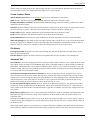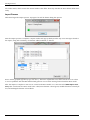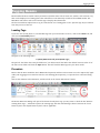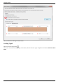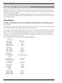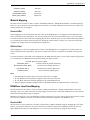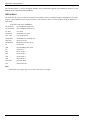
1
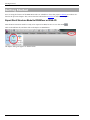
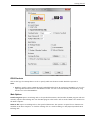
RISA-Revit 2013 Link
General Reference Manual
26632 Towne Centre Drive, Suite 210
Foothill Ranch, California 92610
(949) 951-5815
(949) 951-5848 (FAX)
www.risatech.com
Copyright 2012 by RISA Technologies, LLC All rights reserved. No portion of the contents of
this publication may be reproduced or transmitted in any means without the express written
permission of RISA Technologies, LLC.
We have done our best to ensure that the material found in this publication is both useful and
accurate. However, please be aware that errors may exist in this publication. RISA Technologies, LLC makes no guarantees concerning accuracy of the information found here or in
the use to which it may be put.
Table of Contents
Table of Contents
Introduction
1
Loads
26
How will using Revit Structure and
RISA together help me?
1
Shape Mapping
28
Installing the RISA-Revit Link
1
Material Mapping
29
3
RISAFloor Load Case Mapping
29
Version Information
Appendix B - Mapping Files
Link Information
3
Compatibility Information
3
Download Links
3
Workflow
4
Which Program Should I Start In?
4
Two-Way Integration (Round-Tripping)
5
Examples
6
What if Something Goes Wrong?
7
Getting Started
28
8
Export Revit Structure Model to RISAFloor
or RISA-3D
8
Import RISAFloor or RISA-3D model to
Revit Structure
Tagging Beams
12
17
Loading Tags
17
Procedure
17
Technical Support
21
Appendix A - Data Exchange
22
Floors/Levels
22
Grids
22
Beams
22
Columns
24
Braces
24
Walls
25
In-Place Families
25
Footings
25
Decks/Slabs
25
Materials
26
Boundary Conditions
26
General Reference Manual
I
Introduction
Introduction
Revit Structure has spread the BIM concept (Building Information Modeling) to the structural community, and
RISA is in full support of this new wave of structural design workflow. For this reason, RISA Technologies has
been an Autodesk Authorized Developer for many years. This means that the RISA developers are given full
access to Revit Structure's behind-the-scenes code, as well as advanced alpha and beta copies of new releases.
This version of the RISA-Revit link represents an evolution of many previous versions of the link, and makes
every effort to make the transition between RISA and Revit seamless, robust, and thorough.
How will using Revit Structure and RISA together help me?
The fundamental advantage of linking RISA and Revit Structure together is that it helps you to avoid mistakes,
and eliminate redundancies (duplication of effort). Traditionally, structural models were created in RISA either
from scratch or based off of existing drawings. The model was solved, and then results were printed and used to
manually update drawings. Any simple oversight or typo could cause serious problems. A mistakenly entered
beam size on the drawings meant that an undersized beam would be erected, which could potentially fail. Furthermore, hours were wasted manually transcribing text from one program to another.
Eventually RISA developed a DXF Import/Export process that eliminated some of these problems. AutoCAD drawings could be imported to RISA, although no member sizes or load information could. The DXF import process
strictly established geometry and for basic structures could frequently take as long as modeling from scratch in
RISA. DXF drawings could also be exported from RISA, but they could not 'update' existing drawings, so most of
the drafting work on framing plans had to wait until the structural engineer's analysis was complete. Any
changes made to the structure during a project had to separately be made to both RISA and CAD drawings.
When BIM (Building Information Modeling) started gaining popularity in the form of Revit Structure, it became
apparent that these limitations would no longer exist. By creating a 3D model of smart 'elements' (rather than
just linework) it became possible to link large amounts of information between the drawings (Revit Structure)
and the analysis model (RISA). The concept of round-tripping became introduced, whereby changes and updates
could be continuously shared between models. The RISA-Revit Link exists to make this integration as seamless
as possible.
Installing the RISA-Revit Link
The RISA-Revit Link works best when both RISA and Revit Structure are installed on the same computer. This is
not a strict requirement though. For this reason the installation instructions below present steps for both the
Revit computer and the RISA computer. If both programs are present on one machine then ensure that all steps
are followed for that machine:
Revit Computer
1. Ensure that Revit Structure is installed, and that the version matches that shown on the Version Information page.
2. Open Revit Structure and click on the Communication Center button
. This button can be found along
the top toolbar, in the upper-right corner. Ensure that no product updates are available. If product
updates are listed as available then install them.
3. Download the latest RISA-Revit Link from the RISA website: http://risatech.com/partners/prt_revit.html
4. Close Revit Structure (if it is currently open) and run the installer. Once the installation is complete you
are ready to begin using the RISA-Revit Link.
General Reference Manual
1
Introduction
RISA Computer (may be separate from Revit Computer)
1. Launch RISA-3D, and go to the Help menu. Click on 'Check for Update'. If an update is available then download and install it.
2. Repeat Step 1 for RISAFloor if applicable.
2
RISA-Revit Link General Reference
Version Information
Version Information
Link Information
RISA-Revit Link Version 11.0
Compatibility Information
Product
Version
Revit Structure
2013
RISA–3D
10.0.1 (or Higher)
RISAFloor
6.0.1 (or Higher)
Download Links
Revit Structure
http://risatech.com/partners/prt_revit.html
www.autodesk.com
RISA–3D
Contact RISA
RISAFloor
Contact RISA
RISA-Revit Link
General Reference Manual
3
Workflow
Workflow
There are a variety of options for workflow between RISA and Revit Structure. Before using the RISA-Revit Link
it is best to understand what these are, and how they can best be used for your project.
Which Program Should I Start In?
The RISA-Revit Link encompasses three programs (RISA-3D, RISAFloor, and Revit Structure). Each program has
its own purpose, but all three fully integrate for one complete building design. The reasons for starting in each
program are listed below:
Starting in Revit Structure
This is the most common workflow. The reason is that most Revit Structure models are created based off of
Revit Architecture models. In fact, it is common for the Revit Structure model to use the grids and levels from
the architect's model, in order to ensure coordination between architecture and structural drawings.
Remember that the goal of the Revit model is to represent the physical model as accurately as possible,
whereas the goal of the RISA model is to represent the analytical model as accurately as possible. There are
many circumstances where physical arrangements are better represented in different ways from each other.
A Revit model may have a very complex physical arrangement that can be greatly simplified for structural analysis. By starting in Revit you can model these physical complexities, and assign an analytical arrangement for
RISA to use. If you instead start in RISA, the link will create members in Revit, but it will create them with the
most basic physical geometry, since it does not know your intentions for details.
Take the detail shown below for example. On the left is the Revit representation of a column and beam. On the
right is the RISA representation. The connection details shown in Revit are necessary for construction drawings,
however in RISA a simple 'fixed' connection is sufficient to give an accurate analysis.
A proficient Revit user can assemble a structure in Revit as fast as a proficient RISA user can assemble a structure in RISA. Therefore, especially if the architect has already created a model, it may be fastest to generate a
model first in Revit Structure which uses the architect's model as a template.
Starting in RISAFloor
This is the second most common workflow. RISAFloor and Revit are very similar in their scope, in that they are
both designed around building-type structures which have floors, roofs, and gridlines. This is as opposed to more
industrial structures which do not fit this profile. Most users who start in RISAFloor do so for the following reasons:
4
RISA-Revit Link General Reference
Workflow
1. There is no Revit model from the architect, or the structural analysis must be underway prior to its availability.
2. Your proficiency in RISAFloor modeling exceeds that of Revit modeling, so you can create a building model
much faster by working within RISAFloor.
There are many users who prefer to start the model in RISAFloor, just be aware that after importing to Revit for
the first time your Revit model may need some massaging in order to be ready for construction documentation.
Any RISA-3D elements that are present in the RISAFloor model (from RISAFloor-3D integration) will automatically be transferred over to Revit.
Starting in RISA-3D
It is less common that RISA-3D and Revit would be linked together without also using RISAFloor. While RISA-3D
does link with Revit, it is not constrained by some of the limitations that both Revit and RISAFloor have with
regards to structure type. Revit is a Building Information Modeling program, so some structures which RISA-3D
is well suited for (tanks, bridges, oil platforms, etc) do not fit Revit's mold of clearly defined floor levels and
grids. Since the creation of RISAFloor, and due to its complete integration with RISA-3D, it is rare that RISA-3D is
used on its own for building modeling purposes.
Two-Way Integration (Round-Tripping)
Please note that improvements to the RISA-Revit 2013 Link have revised the methodology listed below, as compared to previous versions of the Link.
Initial Linking Between RISA and Revit Elements
Whenever a RISA model is imported to Revit for the first time, or vice versa, a link is formed between the elements. This link is maintained by the Exchange File, which handles all of the bookkeeping between the two models. For this reason it is important to always use the same Exchange File when transferring back and forth
multiple times (round-tripping). Whenever an Exchange File is exported and "overwrites" a previous version of
the exchange file, it is actually a "merge" of new data into the existing exchange file.
The exchange file maps RISA element ID's with Revit element ID's. For example, a beam in the RISA model with
the label M16 may be represented as a Revit beam with BIM ID #949. The Exchange File maintains a relationship
between M16 and BIM ID #949 in order to track changes and map them between the two programs.
Round Trips (Exporting Revit to RISA)
Every time a Revit model is exported to RISA, the RISA model is made to conform with the Revit model. For
instance, if the link sees a discrepancy between the location of a beam in Revit, and the location of that same
beam in RISA, the Revit location will always trump, and therefore the beam will be moved in the RISA model. Certain element properties (such as beam unbraced lengths) are not mapped between RISA and Revit, so those properties will always be preserved in the RISA model.
Round Trips (Importing RISA to Revit)
Whenever a RISA model is imported to Revit, the Link performs a sophisticated comparison using the RISA model
and the Exchange File to determine what has changed between the RISA model as it currently exists, and what
was exported from Revit during the last Revit to RISA export. Certain element properties which are associated
with a "solution" in RISA are always transferred into Revit regardless. These include:
l
l
l
l
RISAFloor beam and column sizes (when members are set to be optimized)
Number of composite studs
Beam camber
Beam end reactions
General Reference Manual
5
Workflow
Other element properties such as a beam's location or material are only updated in the Revit model if that element was modified within the RISA model. This optimizes the import process and prevents the Link from making
unintended modifications to existing Revit elements, resulting in much faster transfers if few changes were made
within the RISA model.
This differs from older version of the RISA-Revit Link where the properties of all of the Revit elements were
updated from the RISA model, even when nothing had been changed in the RISA model.
Updating Member Sizes Only
The Import from RISA dialog box contains an option to update only the member sizes. This forces the Link to
ignore any changes to Element Geometry (such as the location of a beam or the slope of a roof).
The primary reason for using this option is when a discrepancy in geometry between both models ought to be
maintained. These circumstances have become rare since the analytical adjustment tools in Revit have been
improved. However, there may be circumstances where it is necessary within a RISA model to create "Dummy
Members" which should not be transferred to the Revit model, and this option will prevent those members from
being imported into the Revit model.
Examples
The examples below can help illustrate typical workflow and Link behavior in a way that is easy to understand.
Example A (Model Originating in Revit)
A typical workflow process can be easily understood from the example below:
1. An engineer received an architect's Revit model, and built a Revit Structure model based on the Revit
architectural model.
2. The engineer then exported the Revit Structure model to RISAFloor, however the Link reported that some
elements were not transferred to RISA because the Revit model had errors in it.
3. Before working in RISAFloor, the engineer corrected problems with the Revit model, then exported to
RISAFloor again, this time without any errors.
4. Loads were added to the RISA model, the model was solved, and the beams were sized. From within RISA
a Revit Exchange File was exported, overwriting the existing Exchange File for that project (which was
created upon the first successful export from Revit).
5. The Exchange File was imported back into Revit, completing the first round trip. Because the size of every
member in the model had changed, the import to Revit took several minutes.
Example B (Model Originating in RISA)
A typical workflow process can be easily understood from the example below:
1. An engineer built a RISA model based on architectural drawings, as the architect is not using Revit.
2. From within RISA a Revit Exchange File was exported.
3. A new (blank) Revit Structure model was created, and the Exchange File was imported using the RISARevit Link. This populated the Revit model with all of the members, levels, gridlines, etc. Because the
RISA model was large this import process took several minutes.
4. The engineer then cleaned up the Revit model so that the physical geometry of the elements would
appear correctly on the construction drawings. This required changes such as moving beams downward
using their z-direction offset so that their top flanges were all at the same elevation.
5. The Revit model was then exported back to RISA, therefore completing the first round-trip
Example C (Subsequent Round Trips)
The Link's behavior when dealing with changes to models is illustrated in the example below. Assume that the
model has already completed a successful roundtrip such as those illustrated in Example A or Example B, and
6
RISA-Revit Link General Reference
Workflow
that all of the members have been initially sized in both the RISA and Revit models:
1. The location of a shaft opening was moved in the Revit model. The location and spacing of the beams surrounding the shaft opening was changed accordingly (within the Revit model).
2. The model was then exported to RISAFloor. The redesign members option was left unchecked, ensuring that
RISAFloor would merely check the already established member sizes rather than automatically resizing
the members.
3. The model was solved in RISAFloor, and the engineer had to manually upsize several beams and columns.
From within RISA a Revit Exchange File was exported, overwriting the existing Exchange File for that
project.
4. Concurrently with Step 3, another engineer added a penthouse structure to the roof of the Revit model.
5. The RISA Exchange File was imported into Revit. The import process was very quick, as only a few
members (those that had been modified in RISA) were updated in the Revit model. The penthouse was
unaffected by the import, as the RISA model was unaware of it.
6. A gridline was then moved in the RISA model, and some beams were upsized accordingly.
7. The Revit model was then exported back to RISA so that the penthouse could be designed. The penthouse
came over, however the gridline was moved back to its original location and the other changes made to
the beams in Step 6 were reverted back to match the Revit model.
The problem in Step 7 above stems from the fact that that the workflow fell out of sync between the RISA model
and the Revit model. The engineer should have imported the RISA model to Revit again after Step 6 before sending the Revit model back to RISA to design the penthouse. This happened because unlike RISA to Revit transfers,
the Revit model always trumps the RISA model when discrepancies are found during an export from Revit to
RISA.
What if Something Goes Wrong?
Occasionally a lack of communication between multiple people working on a given model can lead to unintended
mistakes such as Step 7 from Example C above. For this reason the RISA-Revit Link always creates a backup of
the RISA model and the Exchange file before exporting the Revit model to RISA. These files are given an additional file extension of .bak.
If a transfer from Revit to RISA unintentionally changes elements in the RISA model, the pre-export version of
the model can be recovered simply by deleting the new model which has been created, and removing the .bak
that follows .r3d or .rfl (depending on whether it is a RISA-3D or RISAFloor model respectively). The pre-export
version of the exchange file can be recovered by deleting the new exchange file and removing the .bak which follows the .exc.
If a transfer from RISA to Revit unintentionally changes elements in the Revit model, the Undo button in Revit
will revert all of the changes which the Link has made to the model. Additionally, the previous exchange file can
be recovered using the procedure described in the above paragraph.
General Reference Manual
7
Getting Started
Getting Started
Prior to using the features of the RISA-Revit Link it is advisable to learn the proper workflow procedures outlined in the previous chapter. Also, ensure that the link has been installed on the Revit computer.
Export Revit Structure Model to RISAFloor or RISA-3D
Once the Revit Structure model is ready to be exported to RISA, be sure to save the model
.
Click on the Add-Ins tab, and then click on the Export to RISA button.
The Export dialog will appear as shown below:
8
RISA-Revit Link General Reference
Getting Started
RISA Products
Click on the logo of a RISA product in order to specify which one the Revit model should be exported to.
Note:
l
RISAFloor models contain a RISA-3D model embedded within them. By exporting to RISAFloor you are also
exporting RISA-3D information to the RISAFloor model. You can access this 3D-only information by using
the Director tool within RISAFloor.
Main Options
Launch Program exports an Exchange File to the specified destination, then launches the RISA program and automatically imports that Exchange File into the RISA program. This feature will not work if RISA is not installed on
the Revit Computer.
Write to File exports an Exchange File to the specified destination. This option is required for use if RISA is not
installed on the Revit computer. To load the exchange file as a model in RISA go to File\Import\Autodesk Revit
Exchange File.
General Reference Manual
9
Getting Started
Export Selected Items Only exports only the elements currently selected in the Revit Model. When exporting to
RISAFloor it is necessary to select the relevant Reference Levels for the selected items as well. This can be done
easily in an Elevation view within Revit.
Coordinate Base Point specifies which Revit base point will be used to establish an origin (0,0,0) for coordinates
in the RISA model. Choosing "Project" means that the "Project Base Point" will be used as the origin for all three
global axes. Choosing "Survey/Shared" means that the "Survey Point" will be used. Survey Points are typically
used with the Shared Coordinates feature in Revit, which allows a common coordinate system to be used across
multiple Revit models.
It is important to choose one of the two base points, and maintain the use of that base point throughout all transfers back and forth. To see the location of both points in the Revit Model look under the Architecture Filter List
in the Visibility/Graphic Overrides, under the Site category.
Orient to True North allows the export of Revit models to RISA using "True North" as the vertical plan direction, as opposed to "Project North". Revit allows a discrepancy between True North as dictated by surveying and
"Project North" (Plan North) such that floor plans are not shown as skewed on drawings. If a structure is
exported to RISA using True North then it is unlikely that the framing will align with RISA's Global Axes, which
makes the generation of lateral loads difficult.
Merge Tolerance specifies a tolerance below which the RISA-Revit Link will automatically connect elements that
are very close to each other. This is especially useful in the case of beams that (accidentally) only nearly intersect in the Revit model.
Footing Tolerance specifies a tolerance below which the RISA-Revit Link will automatically connect footings
that are very close to columns. RISA requires footings to fall directly beneath columns, so any footing not associated with a column will be ignored.
Export Options
Redesign Members is a RISAFloor specific option. In RISAFloor a Shape Group may be assigned to members
(beams, columns, etc) from which the program will automatically choose an optimum size. An example of a Shape
Group would be "Wide Flange", as opposed to an explicit Shape such as "W24x55"
When this box is checked the RISA-Revit Link will ignore the explicit member size specified in the Revit model,
and instead assign a corresponding shape group to the member in RISAFloor. This means that the member size
in Revit will be ignored, and that RISAFloor will optimize the member size.
Walls specifies whether walls (and their openings) should be exported to the RISA model.
Footings & Boundary Conditions specifies whether footings, and boundary conditions should be exported to the
RISA model. These footings are created as RISAFoot footings within the RISA-3D model. At this time RISAFoundation is not supported in the RISA-Revit Link.
Slabs and Openings specifies whether the slab edges, opening edges, and decks are to be created in RISAFloor
based on their geometry in the Revit model. Because RISA has more limitations on slab edge geometry than
Revit, the Link may modify the slab edges to be compatible with RISAFloor. These modifications may be transmitted back to Revit when importing from RISA, so it may not be advisable to keep this option checked when
returning to Revit.
Loads specifies whether loads should be exported to the RISA model from Revit.
Load Combinations specifies whether load combinations should be exported to the RISA model from Revit.
File Names
Exchange File Name designates the name of the Exchange File that will be created by the Link. Browse to a target folder in which this file will be created, or browse to an existing Exchange File that is to be updated.
10
RISA-Revit Link General Reference
Getting Started
The Exchange File acts an intermediary between RISA and Revit. It contains data that is not stored in either the
RISA or Revit files. This data allows the link to keep track of both models to ensure that they are linked correctly.
If you already have an Exchange File for the current project then be sure to specify that same file (as opposed to
specifying a new one). The new information will be merged into the existing Exchange File.
Base File Name designates the name of the base file (RISA model file) that will be created from the exchange
file. By default this will be given the same name and placed in the same location as the exchange file. Browse to
a target folder in which this file will be created, or browse to an existing base file that is to be updated.
Export Process
Click OK to begin the export process. A progress bar will be shown during this process.
Once the export process is complete a Report window will pop up which provides any error messages related to
the export, along with a summary of elements exported.
Errors will be grouped together by type. Use the +/- buttons to expand the trees and read each error. It is best
to correct problems with the Revit model which generate errors before moving forward with the RISA model.
If the Launch Program option was selected during export then the RISA program will automatically be launched.
If Write to File was selected then you must import the exchange file into RISA. Launch the relevant
RISA program, and Import the Autodesk Revit Exchange File using the File Menu.
General Reference Manual
11
Getting Started
After importing the Exchange File, RISA automatically creates a corresponding base (model) file in the same
folder as the exchange file. Import RISAFloor or RISA-3D model to Revit Structure
Save the latest changes in the RISAFloor or RISA-3D model, then Export an Exchange File using the File Menu. If
you already have an Exchange Eile for the current project then be sure to overwrite that same file (as opposed
to creating a new one). Any changes will be merged into that file during the "overwrite" process.
If the exchange file was created successfully, an export confirmation dialog appears.
12
RISA-Revit Link General Reference
Getting Started
Note:
l
The default Exchange File import/export directory can be set using the Tools > Preferences menu of the
RISA program.
Open Revit Structure if it is not already open, and either open an existing model or create a new model into
which the RISA model will be imported.
Once the Revit Structure model is ready for RISA Import, be sure to save the model
.
Be sure that the current (active) view in Revit is a 3D view.
Click on the Add-Ins tab, and then click on the Import from RISA button.
The Update From RISA dialog will appear:
General Reference Manual
13
Getting Started
Import Options
Merge Tolerance specifies a tolerance below which the RISA-Revit Link will automatically connect elements that
are very close to each other. This is especially useful in the case of beams that (accidentally) only nearly intersect in the Revit model.
Coordinate Base Point specifies which Revit base point will be used to establish an origin (0,0,0) for insertion of
the RISA model. Choosing "Project" means that the "Project Base Point" will be used as the origin (0,0,0) for all
three global axes of the RISA model. Choosing "Survey/Shared" means that the "Survey Point" will be used. Survey Points are typically used with the Shared Coordinates feature in Revit, which allows a common coordinate
system to be used across multiple Revit models.
It is important to choose one of the two base points, and maintain the use of that base point throughout all transfers back and forth. To see the location of both points in the Revit Model look under the Architecture Filter List
in the Visibility/Graphic Overrides, under the Site category.
Orient to True North allows the import of RISA models to Revit using "True North" as the vertical plan direction, as opposed to "Project North". Revit allows a discrepancy between True North as dictated by surveying and
"Project North" (Plan North) such that floor plans are not shown as skewed on drawings. Most RISA models are
14
RISA-Revit Link General Reference
Getting Started
laid-out along the Global X and Y axes, which would typically correspond with the plan-horizontal and plan-vertical directions in Revit. Such models should be imported to "Project North".
Create / Update / Delete
Update Member Sizes Only See the Workflow topic for more information on this option.
Walls specifies whether walls (and their openings) should be imported to the Revit model.
Footings & Boundary Conditions specifies whether RISAFoot footings, and joint boundary conditions should be
imported to the Revit model.
Reactions specifies whether beam end reactions should be imported to the Revit model. An option exists to scale
the end reactions, or specify a minimum value which smaller reactions should be rounded up to.
Project Grids specifies whether RISA project grids should be imported to the Revit model.
Loads specifies whether loads should be imported to the Revit model from RISA.
Load Combinations specifies whether load combinations should be imported to the Revit model from RISA.
Slabs and Openings specifies whether the slab edges, opening edges, and decks are to be created in Revit based
on their geometry in the RISAFloor model. If the slab edges were simplified in the RISAFloor model in order to
facilitate analysis it may not be advisable to have this box checked on the return trip to Revit.
File Names
Exchange File Name designates the name of the Exchange File that will be loaded by the Link. Browse to the
folder in which this file exits.
Base File Name designates the name of the base file (RISA model file) that is linked to the exchange file.
Advanced Tab
Clear BIM IDs is useful for changing which Revit model your RISA model is linked to. Once a RISA model is linked
with a Revit model, the Link stores the BIM IDs (tags which relate RISA members to Revit members) within the
RISA model. If this RISA model is then linked to a different Revit model, it still contains associations to the original Revit model, which can cause problems with the new Revit model. Clearing these IDs allows the RISA model
to correctly link with the new Revit model.
Set all beams' Horizontal Projection to Centerline is used in models where beams are placed very close to
other elements (such as beams or walls) whereby Revit automatically snaps the beam's analytical line to align
with the other element. Using this option effectively disables that auto-snapping feature, and maintains correct
analytical geometry. This option will set all beams to have a centerline horizontal projection though, so any
intentional horizontal projections within the Revit model will also be reset.
Do not use optimized import process exists for advanced troubleshooting purposes. This bypasses the smart
comparison of what changed between the RISA model and the Revit model and instead forces a wholesale geometric update of the Revit model from the RISA model, regardless of whether any items have changed since the
last transfer.
Shape Library Options allows you to specify which Revit libraries are used to load shapes when importing from
RISA. When the Link searches for a shape to be loaded into the Revit model it will look at these libraries in
sequential order.
The Imperial and Metric library paths are set in the Revit File Locations defaults. You can also specify a path to
a custom library (by checking the Use Custom Library box), which the Link will use if it cannot find the shapes in
the Revit libraries.
When using custom libraries you must browse to a folder which has a subfolder titled Structural. The Structural
folder must have subfolders titled Columns and Framing respectively. Those folder must then have material-spe-
General Reference Manual
15
Getting Started
cific folder names, which contain the custom families. This folder hierarchy matches the Revit default folder hierarchy.
Import Process
Click OK to begin the import process. A progress bar will be shown during this process.
Once the import process is complete a Report window will pop up which provides any error messages related to
the export, along with a summary of elements added, modified, or deleted.
Errors will be grouped together by type. Use the +/- buttons to expand the trees and read each error. It is best
to correct problems with the RISA model which generate errors before moving forward with the Revit model.
After the import is complete a new view is created in the Revit model. It is a 3D view titled RISA Import Summary. This view shows the entire model color coded, new elements colored green, modified elements colored yellow, and unchanged elements colored black.
16
RISA-Revit Link General Reference
Tagging Beams
Tagging Beams
Beams within the Revit model contain parameters (member data such as beam size, camber, end reactions, etc)
that can be displayed on framing plans. This information is automatically transferred from RISA models. The
RISA-Revit Link comes with several useful tags to display this information.
The directions below explain how to tag all of the beams in a framing plan at once. Specific tags may be omitted
from this process if desired.
Loading Tags
If you have not already done so, load the RISA tags into your Revit model. To do so, click on the Insert tab, and
click on the Load Family button.
Navigate to the following folder:
C:\RISA\RISA Revit Link_2013\Beam Tags\
The path for the folder above may be different if you did not install the link in the default location. Select all of
the files in that folder and click the Open button. This will load the RISA tags into your Revit model.
Procedure
Ensure that the Revit model has had a RISA model imported, and that end reactions were also imported (if applicable). The tagging process much be done for each framing plan separately, so open the first relevant framing
plan.
Click on the Annotate tab within Revit, and then click on the "Beam Annotations" button:
The Beam Annotation Dialog will open. If the beams already have tags you may want to check the box "Remove
existing beam tags...", which will replace the existing tags with the new RISA tags. Choose between the "Level
beams in plan" and "Sloped beams in plan" tabs as applicable.
General Reference Manual
17
Tagging Beams
The procedure for each tag is shown below:
Loading Tag #1
Click on the Load Tag button
.
Choose the "Structural Framing Tag" radio button, then click in the "Type" dropdown and choose RISA Start Reactions.
18
RISA-Revit Link General Reference
Tagging Beams
Loading Tag #2
Repeat the procedure for Tag #1, loading the Beam Size tag instead.
Loading Tag #3
Repeat the procedure for Tag #1, loading the RISA End Reactions tag instead.
Loading Tag #4
Repeat the procedure for Tag #1, loading the RISA Start Moments tag instead.
Loading Tag #5
Repeat the procedure for Tag #1, loading the Studs and Camber tag instead.
Loading Tag #6
Repeat the procedure for Tag #1, loading the RISA End Moments tag instead.
Applying Tags
The framing tags should now be shown as below:
General Reference Manual
19
Tagging Beams
Click OK in the "Beam Annotations" dialog, and the tags will automatically be applied to the beams. Each tag is
an individual element that may be deleted or moved as necessary.
20
RISA-Revit Link General Reference
Technical Support
Technical Support
Technical support is an important part of the RISA-Revt Link. There is no charge for technical support for all
licensed owners of the current version of RISA-3D and/or RISAFloor. Technical support is very important to the
staff at RISA Technologies. We want our users to able to reach us when they are having difficulties with the Link.
However, this service is not to be used as a way to avoid learning the program or learning how to perform structural modeling in general.
Hours: 6am to 5pm Pacific Time, Monday through Friday
Before contacting technical support, please do the following:
1. Search the Help File or User's Manual. Most questions asked about the RISA-Revit Link are already
answered there. Use the table of contents or index to find specific topics and appropriate sections. We go
to great lengths to provide extensive written and online documentation for the link. We do this in order to
help you understand the link and make it easier to use.
2. Visit our website: http://risatech.com/partners/prt_revit.html. Ensure that you have the latest version of
the RISA-Revit Link. The version number that you are currently running can be viewed at the top of the
import/export dialogs within Revit.
3. Within RISA-3D or RISAFloor click on the Help Menu and select Check for Updates. Occasionally there are
known issues which get corrected in periodic updates released by RISA.
4. Look at your analytical model in Revit to see if anything is wrong with it. Nine times out of ten the errors
that occur during transfer are due to incorrect analytical models.
5. Take a few minutes to experiment with the problem to try to understand and solve it.
Please be prepared to send us your Revit model. If the file size exceeds 5MB then it must be uploaded to our website. You can contact support via e-mail for instructions on how to upload your model to the website. Please
relinquish your worksets, and make sure that all relevant worksets including Levels & Grids are set to active
prior to sending the Revit model. If possible, please send the Central model.
E-Mail: [email protected]
This method is the only way to send us a model you would like help with. Make sure you tell us your name, company name, RISA Key ID (go to Help\About), phone number, and give a decent problem description. Make sure to
specify which program you are integrating with, and whether you are using the "Export Selected Items Only"
option.
Phone Support: (949) 951-5815
Feel free to call, especially if you need a quick answer and your question is not model specific and therefore
doesn’t require us to look at your file.
General Reference Manual
21
Appendix A - Data Exchange
Appendix A - Data Exchange
Floors/Levels
RISAFloor Floors are transferred into Revit as Levels. Revit Levels are transferred to RISAFloor as Floors. The
following properties are supported:
l
l
Level/Floor Name
Elevation
RISA-3D beams and braces (including RISA-3D models embedded within RISAFloor) create Revit levels when
transferred.
Note:
l
l
l
l
RISAFloor does not support negative floor elevations. Revit levels with an elevation below 0'-0" are not
transferred to RISAFloor.
Revit Level names may not exceed 32 characters.
No two Level names in Revit may be the same.
No two Floor names in RISAFloor may be the same.
Grids
Project Grids in RISAFloor and RISA-3D are transferred to Revit as Grids. Revit Grids are transferred to RISAFloor and RISA-3D as Project Grids. The following properties are supported:
l
l
Grid Name
Grid Position
Note:
l
l
l
RISAFloor and RISA-3D grids are not assigned start/end elevations as they are in Revit. Therefore they
are always imported to Revit at 0'-0" elevation.
RISAFloor and RISA-3D grids are not assigned start/end locations in plan as they are in Revit. Therefore
they are always extended to the furthest perpendicular grid lines.
RISAFloor and RISA-3D do not support angled or radial grids. Therefore they are ignored when exported
from Revit. Angled and radial grids are also ignored during the process of importing from RISA to Revit.
Beams
Beams within RISAFloor and Members assigned to Type "Beam" in RISA-3D are both transferred to Revit as Structural Framing Beams. Revit Structural Framing Beams are transferred to RISAFloor as Beams, and to RISA-3D as
Members assigned to Type "Beam".
The following properties are supported:
l
l
l
l
l
l
Rotation Angle
Material
Beam Size
Start/End Releases
Gravity/Lateral Flag
Location
Mapping
The Mapping File is used to match RISA Shape names with Revit Family Instance names. When exporting to RISA3D or RISAFloor, if a matching shape name cannot be found in the mapping file then the beam is created as a
22
RISA-Revit Link General Reference
Appendix A - Data Exchange
rectangular 1"x1" shape.
When importing from RISA-3D or RISAFloor into Revit, if a matching shape name cannot be found in the mapping
file then the beam is not transferred.
A notification will be made in the warning log if any problems occur with beam transfers.
Sloped Beams
RISAFloor only supports sloped beams at the top Floor. Any sloped beams on Revit Levels below the top Level
will be flattened (end offsets set to zero) when transferred to/from RISAFloor.
RISAFloor does not support negative elevation offsets for beams. Any Revit Beam with a negative end offset will
be reset to have zero offset when transferring to/from RISAFloor.
Revit beams must be assigned to a Reference Level in Revit. Sloped beams in RISA-3D are assigned to a Revit
Level at their lower end. The higher end is assigned a corresponding End Offset from the Reference Level.
End Releases
RISAFloor only supports "Pinned" or "Fixed" end releases. If the end releases of a Revit Beam do not correspond
with standard Pinned or Fixed releases then the link chooses the closest match when transferring to RISAFloor.
The Revit end releases in this circumstance are not affected when transferring back to Revit.
Design Lists/Shape Groups
RISAFloor members which are not assigned an explicit beam size are assigned to a Shape Group. The RISA-Revit
Link does not transfer shape groups. The RISAFloor model must be solved, and the results must be saved in
order to transfer the beam sizes chosen by RISAFloor during solution.
RISA-3D Members are assigned a Design List of "None" when transferred from Revit.
Composite/Camber
All RISAFloor beams are created as Composite when transferred from Revit. Both segmented and uniform studs
are transferred back to Revit as beam properties. Beams that are assigned Camber in RISAFloor have their
camber transferred to Revit as a beam property. The RISAFloor model must be solved, and the results must be
saved in order to transfer the studs and camber chosen by RISAFloor during solution.
End Reactions
Beam end reactions are transferred to Revit from both RISA-3D and RISAFloor.
Reactions from RISAFloor are determined as either Unfactored or Factored based on a setting within the RISAFloor Global Parameters.
Reactions transferred from RISA-3D are envelope values determined from the load combinations. The values are
exact shear and moment values determined from Load Combinations, so if Strength-Level Load Combinations
(e.g. 1.2D + 1.6L) are used in RISA-3D then the end reactions sent to Revit will be at strength level.
When a RISA-3D model is integrated with RISAFloor the envelope of the absolute values of shears and moments
is used comparing both RISAFloor and RISA-3D end reactions. This ensures that the controlling reaction is sent to
Revit for lateral members.
The RISAFloor model must be solved, and the results must be saved in order to transfer the end reactions to
Revit. The RISA-3D model must be solved using an Envelope solution, and the results must be saved in order to
transfer end reactions to Revit. Both models must be solved as described above in order to get automatic enveloping of gravity and lateral reactions.
General Reference Manual
23
Appendix A - Data Exchange
l
l
l
l
RISA I-End Maximum Shear is
RISA J-End Maximum Shear is
RISA I-End Maximum Moment
RISA J-End Maximum Moment
mapped to Revit parameter "RISA Start Reaction".
mapped to Revit parameter "RISA End Reaction".
is mapped to Revit parameter "RISA Start Moment".
is mapped to Revit parameter "RISA Start Moment".
Cantilevers
A cantilever beam must be drawn as two elements to transfer from Revit to RISAFloor. The cantilever portion
must have a "Cantilever Moment" assigned to the end which the backspan connects to. The backspan does not
require a corresponding "Cantilever Moment" to be assigned. The link automatically recognizes it as a backspan
for the cantilever.
The two elements are created as one cantilever beam within RISAFloor, so they share the same properties, and
the properties of both Revit elements are updated when importing from RISAFloor.
Columns
Column Stacks within RISAFloor and Members assigned to Type "Column" in RISA-3D are both transferred to
Revit as Structural Columns. Revit Structural Columns are transferred to RISAFloor as Column Stacks, and to
RISA-3D as Members assigned to Type "Column".
The following properties are supported:
l
l
l
l
l
Rotation Angle
Material
Column Size
Gravity/Lateral Flag
Location
Note:
l
l
Gravity Columns from Revit are automatically created as Lateral in RISA-3D and RISAFloor if they share a
node with any lateral elements.
RISAFloor Only: Columns in Revit spanning multiple levels should be created as individual members at
each floor, rather than continuous columns spanning multiple levels. Splices can be adjusted in RISAFloor
and exported back to Revit in order to get an accurate column stack model.
Braces
Members assigned to Type "V-Brace" in RISA-3D are transferred to Revit as Structural Framing Braces. Revit
Structural Framing Braces are transferred to RISA-3D as Members assigned to Type "V-Brace".
Members assigned to Type "H-Brace" in RISA-3D are transferred to Revit as Structural Framing Beams with a
Structural Usage set to Horizontal Bracing. Revit Structural Framing Beams with a Structural Usage set
to Horizontal Bracing are transferred to RISA-3D as Members assigned to Type "H-Brace".
Braces are always created as Lateral elements within RISA-3D. The following properties are supported:
l
l
l
l
l
Rotation Angle
Material
Brace Size
Start/End Releases
Location
Braces transferred to/from RISAFloor are handled in the integrated RISA-3D model within the RISAFloor model.
For that reason they are not visible in RISAFloor directly, however they can accessed using the Director tool.
RISAFloor braces are treated the same as RISA-3D Braces.
Horizontal Braces follow the same guidelines as Beams.
24
RISA-Revit Link General Reference
Appendix A - Data Exchange
Each end of a Vertical Brace must be assigned to a different level. When transferring to Revit these levels are
automatically created for each brace. This may result in a large number of levels being created in the case of
vertical braces used as latticework.
Walls
Wall Panels within RISA-3D and RISAFloor are transferred to Revit as Structural Walls. Revit Structural Walls
are transferred to RISA-3D and RISAFloor as Wall Panels. Additionally, vertical plate elements within RISA3D are transferred to Revit as Structural Walls. The following properties are supported:
l
l
l
l
Structural Usage/Lateral Flag
Rectangular Opening Size/Location
Rectangular Boundary
Location
The Structural Usage parameter within Revit determines whether the wall is exported to RISA as Gravity or Lateral. A Structural Usage of "Shear" or "Combined" results in a lateral wall in RISA. Any other Structural Usage
(other than "Not for Analysis) results in a Gravity will in RISA.
Note:
l
l
l
l
Non-rectangular walls within Revit are created as rectangular in RISA using the smallest possible bounding rectangle.
Wall materials are not mapped.
Walls with columns embedded within them are split at the columns when transferring from Revit to RISAFloor.
Only Wall Opening Elements are transferred from Revit to RISA. Openings defined as "Window Opening",
"Door Opening", and wall profile line sketches are all ignored.
In-Place Families
Structural members that are grouped together in Revit, or part of a higher level Family are transferred using
the link, and are treated as independent elements.
Footings
Footings defined in RISA-3D using RISAFoot are transferred to Revit as Isolated Foundation elements. Isolated
Foundation elements in Revit are transferred to RISA-3D as RISAFoot footings. Only footings that occur directly
beneath (or very near) Structural Columns are transferred. All others are ignored. The following properties are
supported:
l
l
l
Rotation (aligned with Column)
Dimensions (length, width, thickness)
Location
Note:
l
l
RISAFoundation footings are ignored by the Link.
If no RISAFoot solution is present (and saved) then the Maximum Dimensions which are defined in Footing
Definitions are transferred to Revit.
Decks/Slabs
Decks defined in RISAFloor are transferred to Revit as Floor/Roof Elements. Floor/Roof Elements in Revit are
transferred to RISAFloor as Decks.
General Reference Manual
25
Appendix A - Data Exchange
Slab Edges are created in RISAFloor based on the overhang of Revit Floor/Roof Elements. RISAFloor Slab Edges
are not transferred to Revit. Closed-circuits of perimeter beams are used to determine slab edge circuits.
Slab Openings in RISAFloor are transferred to Revit as Floor Opening Elements. Floor Opening Elements in Revit
are transferred to RISAFloor as Slab Openings.
The following properties are supported:
l
l
l
l
l
l
Slab Overhang (approximated)
Deck Thickness
Span Direction
Slab Concrete Strength
Slab Concrete Density (not for self weight)
Slab Elastic Modulus
Note:
l
l
l
For Revit Floor/Roof elements which do not have edges parallel to perimeter beams, the Link creates
RISAFloor Slab Edges which are parallel to the perimeter beams.
Deck self weights are not linked to Revit, and must be defined in Deck Definitions in RISAFloor.
Default decks are ignored by the Link
Materials
RISA Materials assigned to Beams, Columns, and Braces are transferred into Revit. Revit Materials assigned to
Beams, Columns, and Braces are transferred into RISA. Walls are assigned to General Materials. The Mapping
File is used for transferring materials between RISA and Revit. The following material types are supported:
l
l
l
l
l
Hot Rolled Steel
Cold Formed Steel
Concrete
Wood
General
Boundary Conditions
Boundary conditions assigned to Joints in RISA-3D are transferred to Revit as Boundary Conditions. Boundary conditions assigned to elements in Revit are created at Joints in RISA-3D.
Translations, rotations, and spring stiffnesses are supported. Pinned boundary conditions are automatically
applied to the bottom of column stacks transferred to RISA-3D.
Loads
Note:
l
Only loads applied in Global Directions are supported. All others are ignored.
Point Loads
Point and Joint loads defined within RISA-3D and RISAFloor are transferred to Revit as Point Loads. Point Loads
in Revit are transferred to RISA-3D and RISAFloor as Point or Joint loads, depending on whether the load falls on
a member or a joint.
Line Loads
Distributed Loads defined within RISA-3D and RISAFloor are transferred to Revit as Line Loads. Line Loads in
Revit are transferred to RISA-3D and RISAFloor as distributed loads.
Note:
26
RISA-Revit Link General Reference
Appendix A - Data Exchange
l
Revit Line Loads which span multiple members will be broken down into multiple distributed loads when
transferred to RISA-3D.
Area Loads
Area Loads defined in RISA-3D and RISAFloor are transferred to Revit as Area Loads. Area Loads defined in Revit
are transferred to RISA-3D and RISAFloor as Area Loads.
Note:
l
l
l
Revit Area Loads which are defined by more than 4-points are ignored by the Link when transferring to
RISA-3D.
Each Revit Area Load is given its own Area Load definition within RISAFloor. Identical area loads are
lumped into one Definition.
Revit only allows one load case per load. Therefore when importing RISAFloor into Revit, only one load
magnitude will be transferred from a given Area Load Definition. The load chosen will be the first encountered in the following order: LL, DL, OL1, etc..
Load Cases/Categories
Load Cases and Categories are mapped between RISA and Revit using the Mapping File.
Load Combinations
The transfer of Load Combinations between RISA and Revit is limited due to inherent differences in how the programs handle them.
Note:
l
l
l
The "State" flag within Revit maps to the "Service" flag within RISA-3D
The "Type" flag within Revit maps to the "Solve" flag within RISA-3D
RISA-3D only supports load combination nesting up to one level deep. Any further nesting will be ignored
by the Link.
General Reference Manual
27
Appendix B - Mapping Files
Appendix B - Mapping Files
RISA and Revit use different terminologies for Shape Names, Material Names, and Load Categories. These terminologies are linked to each other by a process of "Mapping". Mapping is done using a Mapping file designed to
be customized per your standards.
The Excel based XML mapping file “RISA_Revit_Mapping_File.xml” is installed to the RISA-Revit Link folder. The
Link uses the mapping file during transfers between RISA and Revit. The file consists of three tabs: Shapes, Materials, and RF Load Cases.
Shape Mapping
The Shapes tab consists of three columns: “RISA ShapeName”, “REVIT ShapeName”, and “ShapeType”. There are
many shapes already mapped in the file that is installed. Additional shapes may be added, and existing shapes
may be changed.
The Link looks for shape names from this tab of the spreadsheet. If they are not found, it looks for shape names
that are identical between RISA and Revit, and maps them automatically.
For automatic concrete shape mapping the general conventions must be followed for naming in Revit. For example, rectangular concrete shapes must be named in the format 'a x b' and circular shapes must be named in the
format ' c" '. a, b, and c are the width, depth and diameter respectively. It is important to note that Revit stores
rectangular concrete shape names as ‘width x depth’ whereas RISA stores these names as ‘depth x width’. This
behavior is being accounted for by the Link.
The following ‘Shape Types’ should be used in the Shape Mapping File.
Hot Rolled
WF_SHAPE Wide Flange TUBE_SHAPE Tube
PIPE_SHAPE Pipe
CHANNEL_SHAPE Channel
WT_SHAPE WT
DBL_L_SHAPE Double L
SNGL_L_SHAPE Single L
RECT_SHAPE Rectangular
BAR_SHAPE Bar
TAP_WF_SHAPE Tapered Wide Flange
Wood
NDS_SHAPE Rectangular
NDS_ROUND_SHAPE
Round
Concrete
CRECT_SHAPE Rectangular
CRND_SHAPE Round
CL_SHAPE L Shape
CT_SHAPE T Shape
Joists
KJOIST_SHAPE 28
K Joist
LHJOIST_SHAPE LH Joist
DLHJOIST_SHAPE
DLH Joist
RISA-Revit Link General Reference
Appendix B - Mapping Files
SLHJOIST_SHAPE
SLH Joist
KCSJOIST_SHAPE
KCS Joist
JOISTGIRDER_SHAPE
Joist Girder
WOOD_JOIST_SHAPE Wood Joist
Material Mapping
The Materials tab consists of three columns: “RISA MaterialName”, “REVIT MaterialName”, and “MaterialType”.
There are many materials already mapped in the file that is installed. Additional materials may be added, and
existing shapes may be changed.
Revit to RISA
If the mapping for a particular Revit material exists in the Mapping File, it is mapped over the RISA material
name mentioned on the spreadsheet. The material properties are preserved in RISA, and are not overwritten.
If a material match is not found in the mapping file, the Revit material name is sent to RISA. Material properties
are created based on Revit material properties during the initial transfer, and are not overwritten thereafter
regardless of changes made to the RISA material properties.
RISA to Revit
If the mapping for a particular RISA material exists in the Mapping File, it is mapped over the Revit material
name mentioned on the spreadsheet. The material properties in Revit are updated to the RISA material properties.
If a material match is not found in the mapping file, the RISA material name is sent to Revit. Material properties
are created based on RISA material properties during the initial transfer.
Available Material Types in RISA
CONCRETE_MATL
Concrete Material (Family Instances)
HOT_ROLLED_STEEL_MATL
Steel Material (Family Instances)
NDS_WOOD_MATL
Wood Material (Family Instances)
GENERAL_MATL
General Material (WallTypes)
Note:
l
l
l
l
The RISA Material Name may not exceed 19 characters in length.
No two RISA materials should be mapped to the same Revit material.
No two Revit materials should be mapped to the same RISA material.
Material property changes should be made in both RISA and Revit simultaneously for consistency.
RISAFloor Load Case Mapping
This RF Load Cases tab consists of three columns: “RISA LoadCaseName”, “REVIT LoadCaseName” and “LoadCaseType”. There are many load cases already mapped in the file that is installed. Additional load cases may be
added, and existing shapes may be changed.
RISAFloor is limited to a set of predefined Load Cases (Categories). For this reason, new Revit Load Cases cannot
be created in a RISAFloor model, so the Revit Load Cases must be mapped to the RISAFloor ones.
Revit to RISA
The Load Case of every load that is transferred from Revit to RISA is mapped using the mapping file. If no mapping for a given Revit Load Case is present then the load will be transferred to RISAFloor under the OL4 category. RISA-3D does not have this limitation, so it will create new Load Cases using the Revit names.
General Reference Manual
29
Appendix B - Mapping Files
The “LoadCaseType” is used to distinguish whether the load should be applied to the RISAFloor model, or to the
RISA-3D model embedded within RISAFloor.
RISA to Revit
The Load Case of every load that is transferred from RISA to Revit is mapped using the mapping file. If no mapping for a given RISA Load Case is present then a new Load Case will be created in Revit using the RISA Load
Case name.
Available Load Cases in RISAFloor
DL PreComp
Pre Composite Dead Load
DL PostComp
Post Composite Dead Load
LL- Non Live Load
LL-Reduce Reducible Live Load
LLS - Non Live Load Special
LLS-Reduce
Reducible Live Load Special
RLL- Non Roof Live Load
RLL-Reduce
Reducible Roof Live Load
SL Snow Load
SLN Non Shedding Snow Load
RL Rain Load
OL1 Other Load 1
OL2 Other Load 2
OL3 Other Load 3
OL4 Other Load 4
Dyn Mass Dynamic Mass
VLL Vibration Load
Note:
l
30
RISA Load Case names may not exceed 11 characters in length.
RISA-Revit Link General Reference
Index
Index
A
Annotate 17
B
Exporting 8
F
File Names 10, 15
Floors 22
Base File Name 11, 15
Footing Tolerance 10
Beam Annotations 17
Footings 25
Beam Size 19
Footings & Boundary Conditions 10, 15
Beams 22
BIM ID 15
G
Boundary Conditions 26
Getting Started 8
Braces 24
Grids 22
C
H
Camber 23
Horizontal Projection 15
Cantilevers 24
Columns 24
I
Composite 23
Import Options 14
Coordinate System 10, 14
Import Process 16
Create / Update / Delete 15
Importing 12
D
Data Exchange 22
Decks 25
Design Lists 23
E
End Reactions 23
End Releases 23
Exchange File Name 10, 15
In-Place Families 25
Install 1
L
Launch Program 9
Levels 22
Load Combinations 10, 15
Loads 10, 15, 26
M
Export Options 10
Main Options 9
Export Process 11
Mapping 22
Export Selected Items Only 10
Mapping Files 28
General Reference Manual
i
Index
Materials 26
V
Merge Tolerance 10, 14
Version 3
O
W
Orient to True North 10, 14
Walls 10, 15, 25
P
Website 1
Phone Support 21
Workflow 4
Project Grids 15
Write to File 9
R
Reactions 15
Redesign Members 10
RISA End Moments 19
RISA End Reactions 19
RISA Products 9
RISA Start Moments 19
Round-Tripping 5
S
Shape Groups 23
Shape Library Options 15
Slab Perimeters and Openings 15
Slabs 25
Slabs and Openings 10
Sloped Beams 23
Structural Framing Tag 18
Studs and Camber 19
Support E-Mail 21
T
Tagging Beams 17
Technical Support 21
U
Update Member Sizes Only 15
ii
RISA-Revit Link General Reference