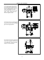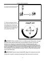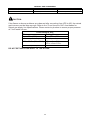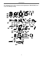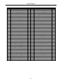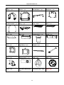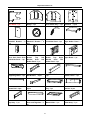
1
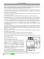
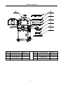
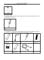
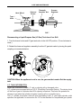
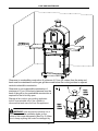
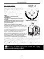
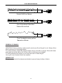
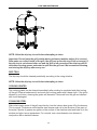
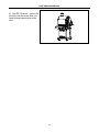
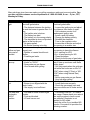
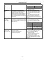
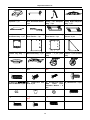
Outdoor Pizza Oven
MODEL # PL8430SSBG070
WARNING
Improper
installation,
adjustment, alteration, service or
maintenance can cause injury or
property damage. Read this
instruction manual thoroughly
before installing or servicing this
equipment.
WARNING
1. Do not store or use gasoline or
other flammable vapors and
liquids in the vicinity of this or
any other appliance.
2. An LP tank not connected for
use should not be stored in the
vicinity of this or any other
appliance.
DANGER
If you smell gas:
1. Shut off gas to the appliance.
2. Extinguish any open flames.
3. Open the oven door.
4. If the odor continues, keep
away from the appliance and
immediately call your gas
supplier or fire department.
WARNING
For Outdoor Use Only
ATTACH YOUR RECEIPT HERE
Serial Number____________________ Purchase Date____________________
1
Questions, problems, missing parts? Before returning to your retailer, call
our customer service department at 1-866-410-0408, Monday - Friday, 8
a.m. - 5 p.m., PST.
Oven Operation 1-2-3
Before Cooking:
Step 1
Keep your oven a safe distance away from your property.*
Step 2
Always perform a leak test.*
Step 3
Keep children away from the oven.
During Cooking:
(To avoid tripping safety valves, please follow these instructions carefully!)
Step 1
Step 2
Turn gas tank on slowly.
Use protective gloves when oven gets hot.
After Cooking:
Step 1
Step 2
Step 3
Burn oven for 10-15 minutes to burn off food residue.
Wait until the oven is completely cooled before closing oven door.
Clean up grease build-up and cover your oven.
* Please refer to the owner's manual for details.
WARNING
DANGER
If you smell gas:
1. Do not store or use gasoline or
other flammable liquids or vapors in
the vicinity of this or any other
appliance.
2. An LP cylinder not connected for
use should not be stored in the
vicinity of this or any other appliance.
1. Shut off gas to the appliance.
2. Extinguish any open flame.
3. Open oven door.
4. If odor continues, keep away from
the appliance and immediately call
your gas supplier or your fire
department.
Always read and understand the WARNINGS and INSTRUCTIONS that are contained in this
manual before attempting to use this gas barbecue grill to prevent possible bodily injury or property
damage.
Always keep this manual for convenient future reference.
2
TABLE OF CONTENTS
Safety Information…………………………………….………...….………….………….…. ………4
Package Contents…..………………..…..….……...…...................………………………………..6
Hardware Contents……………………………………………………………….……………………7
Preparation…..………………..…………………..….……………………………………………..….8
Assembly Instructions……………………..……………….………………………………………...9
Natural Gas Conversion…………………………………………….............................................17
Operation Instruction…………………………….……...……………………………....................23
Care and Maintenance……………………………….………………………………………………32
Troubleshooting …………………………………………………………………..….……………...42
Warranty………………………………………………………………………………………………..44
Explored Diagram……………….……………………………………………………………….…..45
Replacement Parts List…….………………………………………………………………………..47
3
SAFETY INFORMATION
Please read and understand this entire manual before attempting to assemble, operate or
install the product. If you have any questions regarding the product, please call customer
service at 1-866-410-0408 Monday to Friday from 8 a.m. to 5 p.m. PST.
1. The installation of this appliance must conform with local codes or, in the absence of local codes,
with either the National Fuel Gas Code, ANSI Z223.1/NFPA 54, or Natural Gas and Propane
Installation Code, CSA/CGA-B149.1.
2. This oven is intended for use outdoors and should not be used in a building, garage or any other
enclosed or covered area.
3. This outdoor oven is not intended for installation in or on recreation vehicles and/or boats.
4. A minimum clearance of 61 cm (24 inches) from combustible constructions to the sides of the grill
and 61 cm (24 inches) from the back of the grill to combustible constructions must be maintained.
This outdoor cooking gas appliance must not be placed under overhead combustible construction.
5. The use of an electrical source requires that when installed, the grill must be electrically grounded
in accordance with local codes or, in the absence of local codes, with ANSI/NFPA 70, or the
Canadian Electrical Code, CSA C22.1. Keep electrical supply cords and the fuel supply hose away
from heated surfaces.
6. Inspect the hoses before each use for excessive abrasion or wear, or cuts that may affect safe
operation of the grill. If there is evidence of excessive abrasion or wear, or the hose is cut, it must be
replaced prior to the grill being put into operation. The replacement hose assembly must be those
specified by the manufacturer.
7. Keep your oven in an area clear and free from combustible materials, gasoline and other
flammable vapors and liquids.
8. DO NOT obstruct the flow of combustion and ventilation air to this appliance.
9. Keep the ventilation openings of the tank enclosure free and clear from debris.
10. Check all gas connections for leaks with a soapy water solution and brush. Never use an open
flame to check for leaks.
11. Never use charcoal in the oven.
12. Never use the grill in windy areas.
13. Only a 9 kg (20 lb.) LP-gas cylinder is allowed. The
cylinder must be constructed and marked in
accordance with the Specifications for LP Gas
Cylinders of the U.S. Department of Transportation
(D.O.T.) or the National Standard of Canada,
CAN/CSA-B339, Cylinders, Spheres and Tubes for
Transportation of Dangerous Goods. A 9 kg (20 lb.)
LP-Gas cylinder’s dimensions are:
14. Never use the grill without the drip tray installed and
hung under the burner box. Without the drip tray, hot
grease and debris could leak downward and produce a fire hazard.
15. Use only the gas pressure regulator supplied with this appliance. This regulator is set for an
outlet pressure of 11.0 WC.
4
SAFETY INFORMATION
16. The cylinder used must include a collar to protect the cylinder valve.
17. Do not store a spare LP-gas cylinder under or near this appliance.
18. Never fill the cylinder beyond 80 percent full.
19. If the information in “17” and “18” is not followed exactly, a fire causing death or serious injury
may occur.
20. The outdoor cooking gas appliance must be isolated from the gas supply piping system by
closing its individual manual shutoff valve during any pressure testing of the gas supply system at
test pressures equal to or less than 1/2 psi (3.5 kPa).
21. CALIFORNIA PROPOSITION 65 WARNING: The burning of gas cooking fuel generates some
byproducts that are on the list of substances known by the State of California to cause cancer,
reproductive harm, or other birth defects. To reduce exposure to these substances, always operate
this unit according to the use and care manual, ensuring you provide good ventilation when cooking
with gas.
———————————————————————————————————————————
IMPORTANT: We urge you to read this manual carefully and follow the recommendations
enclosed. This will ensure you receive the most enjoyable and trouble-free operation of your
new gas grill. We also advise you retain this manual for future reference.
———————————————————————————————————————————
WARNING: Your grill has been designed to operate using only the gas specified by the
manufacturer on the rating plate. Do not attempt to operate your grill on other gases. Failure
to follow this warning could lead to a fire hazard and bodily harm and will void your
warranty.
———————————————————————————————————————————
WARNING: Make certain your LP (propane) tank is filled by a reputable propane
dealer. An incorrectly filled or an overfilled LP tank can be dangerous. The overfilled
condition combined with the warming of the LP tank (a hot summer day, tank left in
the sun, etc.) can cause LP gas to be released by the pressure relief valve on the
tank since the temperature increase causes the propane to expand. LP gas released
from the tank is flammable and can be explosive. Refer to your Owner’s Manual for
more information concerning filling your LP tank.
5
PACKAGE CONTENTS
PART
A
B
C
G
DESCRIPTION
Main Body
Cooking Grill
Pizza Stone
Flame Tamer
QUANTITY
1
2
1
1
PART
D
E
F
6
DESCRIPTION
Bottom Grill
Fat Cup
Smoker Box
QUANTITY
1
1
1
NATURAL GAS CONVERSION
The following list is included inside the pizza oven carton:
Battery 1 pc
The following list is not included inside the pizza oven carton, but needed when the user is
assembling the pizza oven.
Phillips Head Screwdriver
1 pc
The following list is not included inside the pizza oven carton but is included inside the NG
conversion kit. It is needed when the gas type is changed from LP to NG.
12X12 mm
Wrench 1 pc
Orifice Removal
Tool 1 pc
Phillips Head Screwdriver
pc
φ1.80 Orifice 1 pc
17X19 mm
Wrench 1 pc
Natural Gas Hose 1pc
7
1
Conversion
Screw 1 pc
NATURAL GAS CONVERSION
PREPARATION
Before beginning assembly of product, make sure all parts are present. Compare parts with
package contents list and hardware contents list. If any part is missing or damaged, do not
attempt to assemble the product.
Assembly tip! (Please lightly tighten the screws during assembly of the cart. When the cart
is completed THEN TIGHTEN ALL THE screws. This will make it easier to make all the
holes align properly)
1. Use screw M6*40×2 pcs, nut
M6×2 pcs and flat washer
18*6.4*1×2 pcs to fix the weight
under the base panel. (Note:
These screws MUST be tightened
at this time as it will be hard to
reach them after cart assembly)
2. Use screw M6*12×16 pcs to
attach swivel castor with lock×2
pcs and fixed castor×2 pcs onto
the bottom of the base panel.
(Note: The locking wheels should
go in the BACK of the cart near
the weight)
8
NATURAL GAS CONVERSION
3. Use screw M6*12×2 pcs to fix
the left side panel onto the base
panel of the stand. (Note: The
panel should have the “small
holes at the top” to the front of the
cart assembly)
4. Use screw M6*12×2 pcs to fix
the right side panel onto the base
panel of the stand. (Note: The
panel should have the “small
holes at the top” to the front of the
cart assembly. The Right side
panel also has two(2) small holes
in the middle where you will attach
the door magnet)
5. Use screw M4*10×4 pcs and
nut M4×4 pcs to attach the
transformer assembly onto the
outside of the back panel of the
stand. (Note: These screws can
be tightened at this time)
9
NATURAL GAS CONVERSION
6. Use screw M6*12×5 pcs to
attach the stand base panel onto
the base panel, between the two
side panels.
7. Use screw M4*10×4 pcs to fix
the stand door horizontal beam
between the two side panels.
(Note: Please fasten the upper
two screws first, and then the
lower two screws.)
8. Use screw M4*10×4 pcs to fix
the stand top panel on the top of
the two side panels and back
panel. (Note: These screws can
be tightened at this time)
10
NATURAL GAS CONVERSION
9. Use screw M5*10×8 pcs to
attach triangle×2 pcs on the
bottom of the base panel, leaning
against the two side panels. (Note:
it is CRITICAL that you only insert
the screws with a few turns until all
are in BEFORE you tighten them)
10. Use screw M3*12×2 pcs and
nut M3×2 pcs to attach the door
magnet onto the right side panel.
11. First, insert the door lower axis
into the hole in the base panel.
Next, push down the door upper
spring axis and let go of the spring
when it is pointed to the hole in the
horizontal beam. (Note: You may
need to add 1 or 2 washers
18*6.4*1 on the bottom pin so the
door will close evenly)
11
NATURAL GAS CONVERSION
12. Put the oven assembly on the
stand-top panel. Use screw
M6*12×4 pcs to fasten the oven
onto the stand. (Note: These
screws can be tightened at this
time)
13. Use screw M5*10×16 pcs to
attach side shelf bracket×4 pcs
onto the drawer side panels.
(Note: Arrows face UP)
14. Using one of the screw M5*10
to fix the match holder onto the
front bracket of right side shelf.
(This step may be skipped if you
do not want or need a “match
holder” on your unit)
12
NATURAL GAS CONVERSION
14. Use screw M6*12×8 pcs and
special nut TB31-05-03×8 pcs to
hang side shelf×2 pcs onto the
four brackets. (Note: These
screws can be tightened at this
time)
15. Use screw M4*8×3 pcs to fix
the chimney assembly onto the
top of the oven exterior. (Note:
These screws can be tightened at
this time)
13
NATURAL GAS CONVERSION
16. Use screw M5*35×4 pcs to fix
the back heat shield onto the back
panel of the oven. The order is:
screw→back heat shield→heat
insulation washer→flat washer→
oven back panel.
17. Put the following accessories
into the oven and close the oven
door:
- base grill×1 pc
- pizza stone×1 pc
- cooking grill×2 pcs
- smoker box×1 pc (hang on the
cooking grill, exact position is
according to the food position
inside the oven)
- flame tamer×1 pc
18. Insert the fat cup into the back
of the oven.
19. Insert the battery into the
electronic ignition. Unscrew the
button and place battery positive
(+) tip facing OUT. Screw button
back on.
Your complete pizza oven is now
assembled.
14
NATURAL GAS CONVERSION
PREPARATION:
Before beginning conversion, make sure all parts are present. Compare parts with package
contents. If any part is missing or damaged, do not attempt to convert. Contact customer
service for replacement parts.
1. Turn off gas supply, and then remove cap on gas supply side.
2. Recommended: Install a shut-off valve on gas supply side before installing the socket.
3. Socket should be installed by an authorized technician in accordance with the national
fuel gas code (NFPA 54/ANSI223.1).
4. Before inserting plug, turn on gas supply and leak test all connections including the stem
of the shut-off valve and the opening of the socket. For best results, use an ammonia-free
soap and water solution.
OPERATING INSTRUCTION:
Socket
Sleeve
Plug
1. To connect, push back socket
sleeve (Fig. 1).
Fig. 1
2. Insert plug and release sleeve (Fig.
2).
Socket
3. Push plug until sleeve snaps
forward (Fig. 3). (Gas will flow
automatically. Failure to connect plug
properly to socket will inhibit gas flow
to the appliance.)
Sleeve
Fig. 2
4. Test connection with ammonia-free
soap and water solution.
Socket
Sleeve
To disconnect
1. Pull sleeve back. Pull plug out of
socket. (Gas is automatically shut off.)
Fig. 3
2. Close shut-off valve and replace
dust caps on socket and plug.
15
NATURAL GAS CONVERSION
IMPORTANT:
After your outdoor kitchen is converted to natural gas, the working pressure for natural gas
is 7-inche water column (WC). Gas pressure is affected by gas line size and the length of
gas line run from house. Follow the recommendations in the chart below.
Distance
Up to 25 ft.
26 – 50 ft.
51 – 100 ft.
Over 101 ft.
From House to Grill
Tubing Size
3/8 in. DIA
1/2 in. DIA
2/3 in. of run 3/4 in.
1/3 in. of run 1/2 in.
3/4 in. DIA
WARNING:
Place the grill on a flat, level surface.
Before the conversion, make sure all control knobs are in the OFF position, LP tank valve is
closed, and tank is disconnected from regulator and removed from grill.
CONVERSION INSTRUCTION:
Before the conversion, make sure all control knobs are in the OFF position, LP tank valve is
closed, and tank is disconnected from regulator and removed from grill.
19. Before the conversion, make
sure all control knobs are in the
OFF position, LP tank valve is
closed, and tank is disconnected
from regulator and removed from
grill. Next, open the door and
remove the two cooking grills,
smoker box, pizza stone, base grill
and flame tamer.
16
NATURAL GAS CONVERSION
20. Loosen the screws that are
used to fasten the burner (see
picture at right). Use a 10x12 mm
spanner to remove the
thermocouple out from the burner.
Next, pull out the ignition wire from
the electronic igniter. Finally, take
out the whole burner.
21. Use a screwdriver to loosen
the screw that is used to fasten
the burner cover. Turn the burner
cover until the hole marked “NG”
overlaps with the fixing hole on the
burner. Put the screw back into
the holes and tighten again.
22. Use orifice removal tool to
remove theφ1.2 LP orifice from
the pizza oven. And then use the
same tool to fix theφ1.8 NG
orifice back to the position.
17
NATURAL GAS CONVERSION
23. Put the burner back into the
oven and insert the ignition wire
into the original position. Use the
10x12 mm spanner to fix the
thermocouple back into the oven
again. Finally, fasten the burner
with the original screws.
24. Put back the two cooking grills,
smoker box, pizza stone and base
grill into the right position.
25. Use the 17X19 mm spanner to
remove the regulator and then put
on the NG hose. Fasten the hose
using 17X19 mm spanner.
18
NATURAL GAS CONVERSION
26. Use the screw driver to put the
conversion screw into the knob.
27. When converting to natural
gas, please be aware that the low
heat setting of the main burners
and searing burner is “NG LOW,”
as shown on the control panel. “LP
LOW” setting is not applied when
converting to natural gas.
WARNING: Please remember this is an outdoor gas grill. Many areas of the grill
generate extreme heat. We have taken every precaution to protect you from the
contact areas. However, it is impossible to isolate all high-temperature areas.
Therefore, use good judgment and a certain degree of caution when grilling on this
product. We suggest a covered, protected hand during operation of the grill. Do not
move the grill when it is in operation or hot to the touch. Wait until the unit is turned
off and properly cooled down before moving it. Failure to follow this warning could
result in personal injury.
IMPORTANT: Please be aware that the BTU rating of the rotisserie burner will
change after the grill is converted to natural gas. See below chart for reference:
19
NATURAL GAS CONVERSION
Burner
Main Burner
LP Gas
16,000 BTU / Hr
Natural Gas
16,000 BTU / Hr
CAUTION:
If low flames or burner problems are observed after converting from LPG to NG, the natural
gas lines may not be large enough. Refer to the “From House to Grill” chart below for
natural gas supply line specifications. Please contact a plumber to assure proper pressure
at 7-inch water column.
From House to Grill
Distance
Tubing Size
Up to 7.5m (25 ft).
1cm (3/8 in.) DIA
7.9 – 5m (26 – 50 ft).
1.3cm (1/2 in.) DIA
15.5 – 30.5m (51 – 100 ft). 2/3 in. of run 3/4 in.
1/3 in. of run 1/2 in.
Over 30.5 (101 ft).
3/4 in. DIA
DO NOT RETURN YOUR GRILL TO THE STORE.
20
CARE AND MAINTENANCE
Never attach an unregulated gas line to the appliance. Connection to an unregulated
gas line can cause excessive heat or fire.
Verify the type of gas supply to be used, either Natural Gas (N.G.) or Liquid Propane (L.P.),
and make sure the serial plate agrees with that of the supply. Conversion kits are available
separately for an additional cost, which will enable you to convert your grill from L.P. to N.G. or
to convert your grill from N.G. to L.P. Please see your local dealer for more information.
Always have a qualified service technician perform difficult conversions or
modifications.
For natural gas installations, an installer must supply a gas shutoff valve that is easily
accessible to the grill. All installer supplied parts must conform to local codes, or in the
absence of local codes, with the National Electrical Code, ANSI/NFPA 70- 2002, and the
National Fuel Gas Code, NFPA 54-2002/ANSI Z223.1-2002.
All pipe sealants must be an approved type and resistant to the actions of L.P. gases. Never
use pipe sealant on flare fittings. All gas connections should be made by a competent qualified
service technician and in accordance with local codes and ordinances. In the absence of local
codes, the installation must comply with the National Fuel Gas Code, NFPA 54-2002/ANSI
Z223.1-2002. Gas conversion kits may be purchased separately. When ordering gas
conversion kits, have the model number and the type of gas (N.G. or L.P.) used for your
grill on hand.
This grill must be isolated from the gas supply piping system by closing its individual manual
shut-off valve during any pressure testing of the gas supply piping system at test pressures
equal to or less than 1/2 PSIG (3.5 kPa).
The installation of this grill must conform with local codes, or in the absence of local codes,
with National Fuel Code, NFPA 54-2002/ANSI Z223.1a-2002.
Installation in Canada must be in accordance with the Standard CSA B149.1 or B149.2
(installation code for gas burning appliances and equipment) and local codes.
21
CARE AND MAINTENANCE
L.P. GAS INSTALLATION
Gas grills that are set to operate with L.P. gas come with a high capacity hose and regulator assembly.
(Note: Only use the pressure regulator and hose assembly supplied with the grill or a
replacement pressure regulator and hose assembly specified by the manufacturer). This
assembly is designed to connect directly to a standard 9 kg (20 lb.) L.P. cylinder. L.P. cylinders are not
included with the grill. L.P. cylinders can be purchased separately at an independent dealer.
Connecting a Liquid Propane Gas Tank to the
Grill:
1. Open the doors of the cabinet. Place a 9 kg (20
Ib.) tank with foot ring into the tank tray. See Fig. 4.
Make sure the tank valve is in the OFF position.
2. Tighten the retention screw beside the tank tray
to secure the tank. See Fig. 5.
3. Check the tank valve to ensure it has proper
external mating threads to fit the hose and
regulator assembly provided (Type 1 connection
per ANSI Z21.58b-2002).
4. Inspect the valve connection port of the
regulator assembly. Look for damage or debris.
Remove any debris. Inspect hose for
damage. Never use damaged or plugged
equipment.
5. Make sure all burner knobs are in the
OFF position.
6. Connect the hose and regulator assembly
to the tank valve (See Fig. 6). Hand-tighten
the quick coupling nut clockwise to a full
stop.
22
CARE AND MAINTENANCE
Fig. 6
DO NOT use a wrench to tighten because it could damage the quick coupling nut and result in
a hazardous condition.
7. Open the tank valve fully (counterclockwise). Use a soapy water solution to check all
connections for leaks before attempting to light your grill. See “Pre-Operation Leak Testing" on
page 26. If a leak is found, turn the Tank Valve off and do not use your grill until the leak is
repaired.
As shown in Fig. 7a, gas tank must be place vertically. It is unsafe to operate the grill if the gas
tank is not vertical as shown in Fig. 7b.
Fig. 7a
Fig. 7b
WARNING: The Type I connective coupling (see Fig. 7) supplied with your grill
must not be replaced with a different type of grill/tank connection system. Removal will
result in loss of warranty, gas leakage, fire and severe bodily harm.
23
CARE AND MAINTENANCE
Hand Wheel
External
Thread
Thermally
Sensitive Nut
Propane
Regulator
Type I
Valve
PIG 7
Disconnecting a Liquid Propane Gas (LP Gas) Tank from Your Grill:
1. Turn the burner knobs and LP gas tank valve to the full OFF position. (Turn clockwise to
close.)
2. Detach the hose and regulator assembly from the LP gas tank valve by turning the quick
coupling nut counterclockwise.
CAUTION: When the appliance is not in use, the gas must be turned off at the supply
tank.
L.P. TANK INFORMATION
Never use a dented or rusted L.P. tank or cylinder with a damaged valve.
L.P. cylinders are equipped with an O.P.D. (Overfilling Prevention Device). The device shuts
off the flow of gas to a cylinder after 80% capacity is reached. This limits the potential for
release of gas when the cylinder is heated, averting a fire or possible injury.
The L.P. cylinder must have a shut-off valve terminating in an L.P. gas supply cylinder outlet
specified, as applicable, for connection No. 510 in the standard for compressed gas cylinder
24
CARE AND MAINTENANCE
valve outlet and inlet connection ANSI/CGA-V-1. Cylinders must not be stored in a building,
garage, or any other enclosed area. (The L.P. cylinder must have an overfill protection device
and a collar to protect the cylinder valve.)
The L.P. gas supply cylinder must be constructed and marked in accordance with the
specifications for L.P. gas cylinders of the U.S. Department of Transportation (DOT) or the
National Standard of Canada, CAN/CAS-B339, “Cylinders, Spheres and Tubes for the
Transportation of Dangerous Goods and Commission.”
L.P. TANK USE
• When turning the L.P. tank on, make sure to open the valve SLOWLY two (2) complete
turns to ensure proper gas flow. Most gas tanks now come equipped with a leak
detector mechanism internal to the tank. When gas is allowed to escape rapidly, it shuts
off the gas supply. Opening the valve rapidly may simulate a gas leak, causing the
safety device to activate, restricting gas flow and causing low flames. Opening the
valve slowly will ensure this safety feature is not falsely triggered.
• When not in use, gas supply cylinder valve is to be in the “OFF” position.
• The tank supply system must be stored upright to allow for vapor withdrawal.
• The regulator and hose assembly must be inspected before each use of the grill. If there is
excessive abrasion or wear or if the hose is cut, it must be replaced prior to the grill being used
again.
• Cylinders must be stored outdoors out of the reach of children and must not be stored in a
building, garage or any other enclosed area.
• Only a qualified gas supplier should
refill the L.P. tank.
• Place dust cap on cylinder valve
outlet whenever the cylinder is not in
use. Only install the type of dust cap
on the cylinder valve outlet that is
provided with the cylinder valve. Other
types of caps or plugs may result in
leakage of propane.
WARNING
DO NOT store a spare L.P. gas cylinder under or
near the grill. Never fill the cylinder beyond 80%
full.
If this information is not followed exactly, a fire
causing death or serious injury may occur.
PRE-OPERATION LEAK TESTING
Although all gas connections on the grill are leak tested prior to shipment, a complete gas
tightness check must be performed at the installation site due to possible shifting during
shipment, installation or excessive pressure unknowingly being applied to the unit. Periodically
check the whole system for leaks and immediately check the system if the smell of gas is
detected.
1. Do not smoke while leak testing.
2. Extinguish all open flames.
3. Never leak test with an open flame.
4. Mix a solution of equal parts mild detergent or liquid soap and water.
25
CARE AND MAINTENANCE
5. Turn off the burner control knobs.
6. Turn the top knob of the fuel supply cylinder counterclockwise two (2) rotations to open.
7. Apply the soap solution to connections of the fuel supply assembly. If no soap bubbles
appear, there is no gas leak. If bubbles form at the connections, a leak is detected. If a leak is
detected, immediately turn off the gas supply, tighten any leaking fittings, turn gas on, and
repeat steps 1-3.
8. Turn off the knob on the fuel supply cylinder.
9. Turn on the burner control knobs for a moment to release the pressure in the hose, then turn
the control knobs back off.
10. Wash off soapy solution with cold water and towel dry.
Check all gas supply fittings before each use and each time the gas supply cylinder is
connected to the regulator. Have a qualified service technician leak test the grill any time a part
of the gas system is replaced.
It is also recommended that you perform a leak test at least once a year whether or not the L.P.
gas supply cylinder has been disconnected.
WARNING When leak testing this appliance, make sure to test and tighten all loose
connections. A slight leak in the system can result in a low flame or hazardous condition. Most
L.P. gas tanks now come equipped with a leak detector mechanism internal to the tank. When
gas is allowed to escape rapidly, it shuts off the gas supply. A leak may significantly reduce the
gas flow, making the grill difficult to light or causing low flames.
If you cannot stop a gas leak, turn off the gas supply and call your local gas company. If
necessary, replace the faulty part with the manufacturer’s recommended replacement part. A
slight leak could cause a fire.
WARNING Do not use the grill in garages, breezeways, sheds or any enclosed area.
Never operate the grill in enclosed areas as this could lead to a carbon monoxide buildup,
which could result in injury or death. Place the grill on a level surface. Avoid moving the grill
while it is in operation.
NOTE: The grill will operate best if it is not facing directly into the wind.
26
CARE AND MAINTENANCE
Clearance to combustible construction: A minimum of 61 cm (24 inches) from the sides and
back must be maintained from the gas grill above and below the cooking surface to adjacent
vertical combustible construction.
Clearance to non-combustible construction: A
minimum of 61 cm (24 inches) clearance from the
back of the grill to non-combustible construction is
required for the lid to fully open.
Storage of an outdoor gas cooking appliance
indoor is permissible only if the cylinder is
disconnected and removed from the appliance.
WARNING Heat and smoke exhaust out of
the chimney and the ventilation holes on the
bottom of two oven side panels (See Fig. 8). Make
sure to keep anything that could be damaged by
27
CARE AND MAINTENANCE
heat or smoke away from the heat and smoke
exhaust holes.
GENERAL RULES
Do not leave the grill unattended while cooking!
1. Make sure the grill has been leak-tested and is properly located.
2. Light the grill burners using the instructions provided in this manual.
3. Turn the control knobs to desired temperature - High or Low - and preheat the grill for 10
minutes before cooking.
4. Adjust heat settings to meet your cooking needs for desired results.
5. Allow grill to cool down, wipe off any splatters or grease and clean the drip tray as needed.
6. Do not put a cover on the grill while it is still hot as it could start a fire.
Do not attempt to “light” the grill if the odour of gas is
present!!
BEFORE AND AFTER LIGHTING
1. Ensure your grill is located on a level surface.
2. Keep the gas grill area clean and free from combustible materials, gasoline, and other
flammable vapors and liquids.
3. Ensure nothing is obstructing the flow of combustion and ventilation air.
4. Ensure the ventilation of the cylinder enclosure is free and clear of debris.
5. Visually check burner flames.
WARNING Check the gas supply line for cuts, wear or abrasion.
Always keep your face and body as far away from the grill as possible when lighting.
28
CARE AND MAINTENANCE
GRILL BURNER LIGHTING
Warning: Do not lean over grill when lighting. Turn
off LP supply at cylinder when appliance is not in
use.
Main Burner Lighting Illustration:
1. Check that the control knobs are in the OFF
position.
2. Open valve at tank fully by turning
counterclockwise.
3. The door must always be in the OPEN position
for lighting;
4. Push the Electronic Ignition down 3 to 4 seconds
while turning the control knob to the HIGH position.
The burner should ignite.
Main Burner Control Knob
If ignition does not take place within 5 seconds,
immediately turn the control knob to the OFF position. Wait
5 minutes and repeat step 4 above or refer to match lighting
instructions in manual.
If by chance the electronic igniter does not light the burner,
the burner may be lit with a match attached to the match
extender, located on the inside of the cabinet door.
Remove the base grate and pizza stone. Keep your face as
far away from the burner surface as possible and pass the
match extender to the ports of the main burner tubes.
Position the match near the burner ports and push and turn
the control knob counterclockwise to the “HIGH” position. After the burner has lit, turn the knob
to the "LP LOW" position and carefully place the flame tamers and grates back in position.
Then turn the control knob to the desired setting.
NOTE: If the grill will not light after several attempts see the Troubleshooting section of
this manual. Turn the control knobs to the OFF position when not in use.
Keep any electrical supply cords and the fuel supply
away from any heated surfaces.
29
CARE AND MAINTENANCE
USING THE GRILL LIGHT
Light Operation Instruction
1. Make sure the light’s power switch on the control panel is in the “OFF” position.
2. Connect power plug to properly grounded outlet.
3. Turn the light’s power switch to “ON.”
WARNING
Keep any electrical supply cord away from any heated surface.
Do not turn on the lights when the hood is closed.
IMPAIRED VENTILATION OF HOT AIR FROM GRILL - In order for the burners to function
properly, hot air created by the burners must have a way to escape. The burners may become
deprived of oxygen, causing them to backfire, especially if the burner output is set at HIGH. If
this occurs repeatedly, the burners may crack. This is the reason your grill was designed with
ventilation louvers. These design features give the hot air an escape route. Accordingly, never
operate your grill with very little or no open space at the cooking surface (the cooking grids
provide sufficient space). Also, never cover the ventilation louvers with foil or other materials
that prevent air flow. Specifically, do not cover the entire surface with foil, a large pan, etc.
GENERAL MAINTENANCE
- Keep outdoor cooking gas appliance area clear and free from combustible materials,
gasoline and other flammable vapors and liquids.
- Do not obstruct the flow of combustion and ventilation air.
- Keep the ventilation openings of the cylinder enclosure free and clear from debris.
- Visually check the burners.
30
CARE AND MAINTENANCE
Normal:Soft blue flames
Out of Acjustment:Hard blue
flames-too much air
Poor Combustion:wavy,yellow
flames-too little air
GENERAL CLEANING
IMPORTANT: Before cleaning, make sure all controls are off and the grill is cool. Always follow
label instructions on cleaning products.
For routine cleaning, wash with soap and water using a soft cloth or sponge. Rinse with clean
water and dry at once with a soft, lint-free cloth to avoid spots and streaks.
To avoid scratching the surface, do not use steel wool to clean the grill.
Use a grill cover to protect finish from weather.
GREASE CUP
The grease cup should be cleaned periodically to prevent heavy buildup of debris.
31
CARE AND MAINTENANCE
NOTE: Allow the drip tray to cool before attempting to clean.
Important: Do not leave the grill outside during inclement weather unless it is covered.
Rain water can collect inside of the grill, the grill cart or the drip tray if left uncovered. If
the drip tray is not cleaned after use and the grill is left uncovered, the drip tray will fill
with water causing grease and water to spill into the grill cart. We recommend cleaning
and storing the drip tray after every use.
DRIP TRAY
The drip tray should be cleaned periodically according to the using situation.
NOTE: Allow the drip tray to cool before attempting to clean.
COOKING GRATES
The cooking grates can be cleaned immediately after cooking is completed and after turning
off the grill. Wear a barbecue mitt and scrub the cooking grates with a damp cloth. If the grill is
allowed to cool down, cleaning the grates will be easier if removed from the grill and cleaned
with a mild detergent.
STAINLESS STEEL
After initial usage, areas of the grill may discolor from the intense heat given off by the burners.
This is normal. Purchase a mild stainless steel cleaner and rub in the direction of the grain of
the metal. Specks of grease can gather on the surface of the stainless steel and bake on to the
surface and give a worn appearance. For removal, use a non-abrasive oven cleaner in
conjunction with a stainless cleaner.
32
CARE AND MAINTENANCE
NOTE: Always scrub in the direction of the grain.
GRILL LIGHT
Bulb Replacement
IMPORTANT SAFETY INSTRUCTIONS
Lighted lamp is HOT:
WARNING -TO REDUCE THE RISK OF FIRE, ELECTRIC SHOCK, EXPOSURE TO
EXCESSIVE UV RADIATION, OR INJURY TO PERSONS.
1. Turn off/unplug and allow to cool before replacing bulb (lamp).
2. Bulb (lamp) gets HOT quickly! Only contact switch/plug when turning on.
3. Do not touch hot lens, guard, or enclosure.
4. Do not remain in light if skin feels warm.
5. Do not look directly at lighted lamp.
6. Keep lamp away from materials that may burn.
7. Use only with a 10-watt or smaller bulb (lamp).
8. Do not touch the bulb (lamp) at any time. Use a soft cloth. Oil from skin may damage bulb
(lamp).
9. Do not operate the portable luminaries with a missing or damaged guard, lamp containment
barrier, or UV filter.
Definitions:
(+) Guard – Guard is a portion of portable luminaries unit that prevents inadvertent contact with
the bulb. It may be integrated with the UV filter or lamp containment barrier or as part of an
enclosure or shade.
(+) Lamp containment barrier – lamp containment barrier is a portion of a portable luminaries
unit that encloses the bulb.
(+) UV filter – UV filter is a portion of a portable luminaries unit that limits ultraviolet (UV)
emissions.
33
CARE AND MAINTENANCE
28. Turn off/unplug and allow to
cool before replacing bulb (lamp).
Next, open the door and remove
the two cooking grills, smoker box,
pizza stone, base grill and flame
tamer.
29. Use screw driver to loosen
M5*35 screw * 4 pcs that fix the
heat shield. And then remove the
heat shield.
30. Use screw driver to loosen the
screw that fix the light assy.
34
CARE AND MAINTENANCE
31. Use one hand to hold the
metal back part of the light and
one handle to hold the front glass
cover and then take them apart.
Then you can replace the bulb.
32. After replacement, use one
hand to hold the metal back part of
the light and one handle to hold
the front glass cover and then clip
them together in the right position.
35
CARE AND MAINTENANCE
33. Use M4*10 screw to fix the
light assy. on to the back panel of
the oven.
34. Use screw M5*35×4 pcs to fix
the back heat shield onto the back
panel of the oven. The order is:
screw→back heat shield→heat
insulation washer→flat washer→
oven back panel.
35. Finally, put back the two
cooking grills, smoker box, pizza
stone, base grill and flame tamer
into the oven. Now you have
finished replacing the bulb.
36
CARE AND MAINTENANCE
Cleaning Method
Follow Steps 28 to 31 above for glass cover removal. Use a damp towel to clean the surface
of glass cover. Make sure the glass cover is completely dry before reinstalling.
WARNING
Make sure the light switch is on “OFF” position and power plug is disconnected from
power outlet prior to cleaning the glass cover.
WARNING
The light glass cover should not be in contact with water or any other liquid when it is
warm. Sudden changes of temperature may cause cracks on glass cover.
WARNING
To ensure continued protection against electric shock:
1. Connect to properly grounded outlets only.
2. Do not expose to rain.
3. Keep extension cord connections dry and off the ground.
Bulb specification
Bulb Type: Halogen
Wattage: 10 watts per bulb
Voltage: 12 volts
Please contact customer service at 1-866-410-0408 for assistance on bulb replacement.
Replacing Battery for Electrical Igniter:
1. Remove the igniter cap by turning clockwise;
2. Replace the battery;
3. When installing new battery, ensure it is installed
with the proper polarity;
4. Put on the igniter cap back by turning
counterclockwise.
WARNING:
1. To protect against electric shock, do not immerse cord or plugs in water or other liquid.
2. Unplug from the outlet when not in use and before cleaning. Allow to cool before putting on
or taking off parts.
3. Do not operate any outdoor cooking gas appliance with a damaged cord, plug, or after the
appliance malfunctions or has been damaged in any manner. Contact the manufacturer for
repair.
4. Do not let the cord hang over the edge of a table or touch hot surfaces.
37
CARE AND MAINTENANCE
5. Do not use an outdoor cooking gas appliance for purposes other than intended.
6. When connecting, first connect plug to the outdoor cooking gas appliance then plug
appliance into the outlet.
7. Use only a Ground Fault Interrupter (GFI) protected circuit with this outdoor cooking gas
appliance.
8. Never remove the grounding plug or use with a two-prong adaptor.
9. Use only extension cords with a three-prong grounding plug, rated for the power of the
equipment, and approved for outdoor use with a W-A marking.
OVEN DOOR CLEANING
36. Loosen the M4*10 screw * 4
pcs that fix the oven door and then
take the oven door apart from the
oven.
37. Loosen the M4*10 screw * 7
pcs that fix the door exterior and
interior, and then loosen the
M4*10 screw * 4 pcs that fix the
door hinge. Then Loosen the
shoulder screw that fix the door
handle.
38
CARE AND MAINTENANCE
38. Use spanner 19# to loosen the
nut that fix the temp. gauge. And
then you can completely separate
the oven door exterior and interior
so as to do the cleaning.
39. After cleaning, you need to
re-assemble the oven door. Put
the door interior onto the exterior
and make every screw hole in line
with each other. Use M4*10 screw
* 7 pcs to fix the door interior and
exterior. And then use shoulder
screw to fix the handle onto the
door. Finally, use M4*10 screw * 4
pcs to fix the hinge onto the door.
40. Use spanner or hand directly
to tighten the nut that fix the temp.
gauge on the glass. You can set
the torque of the spanner at
4.0kgf*cm.
39
CARE AND MAINTENANCE
41. Use M4*10 screw * 4 pcs to fix
the door onto the oven. Now you
have finished cleaning the oven
door.
40
TROUBLESHOOTINGE
Many solutions given here can make your grilling experience safer and more enjoyable. You
can also call the customer service department at 1-866-410-0408, 8 a.m. – 5 p.m., PST,
Monday to Friday.
PROBLEM
Grill will not
light.
Burner flame is
yellow and gas
odor can be
smelled.
POSSIBLE CAUSE
1. The ignition wire came off the
electrical igniter/valve.
2. The distance between the ignition
pin and the burner is greater than 3~5
mm.
3. The ignition wire is broken.
4. The battery has died.
5. The battery is in the wrong polarity.
6. The electrode tip does not produce
sparks at the burner port.
7. No gas supplied.
8. Air shutter opening is too big.
1. The air shutter opening is not
properly set.
2. Spiders or insects block the air
shutter.
3. Possible gas leaks.
Excessive
flare-up.
1. Grilling fatty meats.
2. Knobs on “HIGH.”
3. Spray water on gas flames.
4. Hood closed when grilling.
Burner blows
out.
1. LP tank is empty.
2. Burner is not aligned with the
control valve.
3. Gas supply is not sufficient.
Low heat with
the knob in
“HIGH”
position.
1. Low heat is found in natural gas
models.
2. Ports are blocked.
3. LP tank has run out.
41
CORRECTIVE ACTION
1. Reconnect the ignition wire to the
electrical igniter/valve.
2. Loosen the ignition pin and adjust
the distance, then fasten it again.
3. Call customer service for a
replacement ignition wire.
4. Install a new AA battery.
5. Change the battery polarity.
6. Reinstall the electrode.
7. Turn on the regulator valve.
8. Loosen the air shutter and adjust
the opening to a smaller size.
1. Loosen the air shutter and adjust
the opening to have blue flames.
1/4 in. opening for LPG.
1/8 in. or less opening for NG.
2. Clean blockages.
3. Check for the source of gas leaks.
1. Move the meats to the warming
rack if flare up continues until flame
settles down.
2. Grill fatty meats when the grids are
cold while the knobs are on the “LP
LOW” (when using LP Gas) or “NG
LOW” (when using Natural Gas)
setting.
3. Never spray water on gas flames.
4. Hood up when grilling.
1. Refill the LP Tank.
2. Install the burner correctly.
3. Check the gas supply hose and
make sure there are no leaks and no
knots.
1. This model is set for 7 in. natural
gas usage. Please check your natural
gas supply system to have correct
gas pressure. Regulator is not
needed for NG model.
Check the orifice if you installed NG
nozzles. Conversion kit provides the
following nozzles:
TROUBLESHOOTINGE
Low heat, LP
gas.
Low heat,
natural gas.
Cooking light
will not turn on.
Burner
Orifice Size
Main Burner
Φ1.8 mm
2. Clear ports of any obstructions.
3. Refill the LP tank.
The propane regulator assembly
Please follow these instructions:
incorporates an excess flow device
1. Make sure all burners are “OFF.”
designed to supply the grill with
2. Open the tank valve and wait 5
sufficient gas flow. Rapid changes in minutes.
pressure can trigger the excess flow
3. Light the burner one at a time
device, providing a low flame and low following the lighting instructions
temperature.
listed on the door liner and Page 25
and 26.
Gas pressure is significantly affected Check your gas line and make
by gas line and length of gas line from corrections by following the chart
house gas line.
below:
From House to Grill
Distance
Tubing Size
Up to 25 ft.
3/8 in. DIA
26 – 50 ft.
1/2 in. DIA
2/3 in. of run 3/4 in.
51 – 100 ft.
1/3 in. of run 1/2 in.
Over 101 ft.
3/4 in. DIA
1. No power supply.
2. Defective Halogen bulb.
3. Internal wiring issue.
1. Check power supply and make
sure it is properly plugged in.
2. Replace the bulb.
3. Check the wiring connections
under the fire box. All wire
connections must be tight. If any
wires are damaged they should be
replaced.
42
WARRANTY
Proof of purchase is required to access this warranty program, which is in effect from the
date of purchase. Customers will be subject to parts, shipping, and handling fees if unable to
provide proof of the purchase or after the warranty has expired.
If you have any questions or problems, call customer service department at
1-866-410-0408, 8 a.m. – 5 p.m., PST, Monday to Friday.
Warranty Provisions:
This warranty is non-transferable and does not cover failures due to misuse of improper
installation or maintenance.
This warranty is for replacement of defective parts only. We are not responsible for incidental
or consequential damages or labor costs.
This warranty does not cover corrosion or discoloration after the grill is used, or lack of
maintenance, hostile environment, accidents, alterations, abuse or neglect.
This warranty does not cover damage caused by heat, abrasive and chemical cleaners, or any
damage to other components used in the installation or operation of the gas grill.
Paint is not warranted and may require touch-up. Items considered to be consumable such as
batteries are not covered under this warranty.
Some states do not allow the limitation or exclusion of incidental or consequential damages, so
the above limitations or exclusions may not apply to you. This warranty gives you specific legal
rights, and you may also have other rights that vary from state to state.
43
Exploded Diagram
For replacement parts, call our customer service department at 1-866-410-0408, 8 a.m. –
5 p.m., PST, Monday to Friday.
5
4
3
2
6
7
1
8
9
14
10
11
12
15
13
17
18
16
19
35
46
34
33
36
37
45
32
38
20
27
29
30
31
39
22
21
28
40
26
41
25
24
43
42
44
51
52
47
49
50
48
53
58
54
57
55
56
59
60
61
63
62
74
64
68
73
72
69
70
71
44
65
66
23
67
Exploded Diagram
No.
1
2
3
4
5
6
7
8
9
10
11
12
13
14
15
16
17
18
19
20
21
22
23
24
25
26
27
28
29
30
31
32
33
34
35
36
37
Part Name
Heat spacer
Back heat-shield
Light assy.
Light bracket
Handle latch
Gas pipe
Chimney assy.
Cooking grill
Smoker box assy.
Pizza stone
Bottom grill
Interior assy.
Round burner assy.
Exterior
Fascia heat shield
Oven front panel
Back panel
Grease tray
Electronic igniter
Nozzle stator
Valve
Viewing window
Door handle assy.
Door heat shield assy.
Left glass fixing bracket
Bottom glass fixing bracket
Round temp. gauge
Right glass fixing bracket
Control fascia
Knob bezel
Control knob
Light switch
Oven door assy.
Oven door hinge
Glass pressing
Left side shelf bracket
Oven left supporting assy.
QTY
4
1
1
1
1
1
1
2
1
1
1
1
1
1
1
1
1
1
1
1
1
2
1
1
1
1
1
1
1
1
1
1
1
2
1
2
1
No.
38
39
40
41
42
43
44
45
46
47
48
49
50
51
52
53
54
55
56
57
58
59
60
61
62
63
64
65
66
67
68
69
70
71
72
73
74
45
Part Name
Grease tray left bracket
Oven back support
Grease tray right bracket
Oven right supporting assy.
Light transformer
Match holder
Camp stove superior girder
Right side shelf bracket
Side bedplate assy.
Rail support
Two part roller rail
Drawer fascia
Door handle
Drawer
Drawer interior
Grease tray
Grease tray stator
Fat cup
Spring hinge assy.
Oven supporting beam
Trolley top panel
Trolley door horizontal beam
Trolley left side panel assy.
Triangle fortified
Trolley back panel
Magnet
Trolley right side panel assy.
Door axis
Trolley door exterior
Trolley door interior
Tank tray assy.
Tank fastener
Base tray assy.
Weight
Swivel castor without lock
Swivel castor with lock
Flame Tamer
QTY
1
1
1
1
1
1
1
2
2
2
2
1
2
1
1
1
2
1
1
1
1
1
1
2
1
1
1
1
1
1
1
1
1
1
2
2
1
Replacement Parts List
1 、 BG070-01
Exterior * 1 pc
Oven
2. BG070-02-00B Oven
Interior * 1 pc
3. BG070-24 Burner
Bracket Beam * 1 pc
4. BG070B-03-01 Oven
Back Panel * 1 pc
5. BG070-03A Oven
Back Heat Shield * 1 pc
6. BG070-10-00B Burner
Assy. * 1 pc
7. BG070-18
Grate * 2 pcs
8.
BG070-17B
Grate * 1 pc
9. BG070-32A
Stone * 1 pc
Pizza
10. BG070-13-00 Smoker
Box * 1 pc
11.
BG070-08-00C
Chimney Assy. * 1 pc
12. BG070B-05A Control
Fascia * 1 pc
13. BG070B-03-02 Light
Bezel * 1 pc
14.
BG0904B-01-10
Light Assy. * 1 pc
15. BG070B-70 Grease
Stopper * 1 pc
16. BG070-19A Gas Pipe
* 1 pc
17. BG070-20A
Assy. * 1 pc
Valve
18.
DHL-128-1Q-2D-1
Electric Igniter * 1 pc
19. BG179-94
Knob * 1 pc
Control
20. BG179-73-00 Knob
Bezel * 1 pc
21. BG070B-66 Orifice
Holder * 1 pc
22.
BG070B-09-03-00
Oven Door Heat Shield *
1 pc
23.
BG070B-09-00B
Oven Door Assy. * 1 pc
24. BG070-45 Oven Door
Hinge * 2 pc
46
Cooking
Base
Replacement Parts List
25. BG070B-38 Oven
Door Glass * 2 pc
26. BG070-30
Gauge * 1 pc
Temp.
27. BG070-12-00 Oven
Door Handle Assy. * 1 pc
28.
Sideshelf
29. BG070B-30-01 Left
Sideshelf Bracket * 2
pcs
30. BG070B-30-02 Right
Sideshelf Bracket * 2
pcs
31. BG070B-57-00 Oven
Left Holder Panel * 1 pc
32. BG070B-58-00 Oven
Right Holder Panel * 1
pc
33. BG070B-59 Oven
Back Seal Panel Oven
Left Holder Panel * 1 pc
34.
BG070B-60-01
Grease
Tray
Left
Bracket
Oven
Left
Holder Panel * 1 pc
35.
BG070B-60-02
Grease
Tray
Right
Bracket
Oven
Left
Holder Panel * 1 pc
36. BG070B-71 Oven
Upper Beam * 1 pc
37. BG070B-65 Oven
Supporting Beam * 1 pc
38. BG070B-64 Drawer
Rail Bracket * 2 pcs
39. BG070-75 Drawer
1 pc
*
40.
BG070B-63-00
Drawer Fascia * 1 pc
41.
BG0614B-04-13
Drawer Rail * 2 pcs
42. MCG4-04-01 Handle *
2 pcs
43. BG070B-61 Grease
Tray * 1 pc
44. BG070B-69 Fat Cup
Bracket * 2 pcs
45. BG070B-62-00 Fat
Cup Assy. * 1 pc
46.
TYQ-9B-LL516-00
Hose and Regulator * 1
pc
47.
DGP350NP-55-00
Match Holder * 1 pc
48. BG070B-73-00 Flame
Tamer Assy. * 1 pc
47
BG070-76-00
* 2 pcs
Replacement Parts List
49. BG070B-53 Trolley
Top Panel * 1 pc
50. BG070B-54 Trolley
Door Horizontal Beam *
1 pc
51.
BG070B-50-00
Trolley Left Sidepanel
Assy. * 1 pc
52.
BG070B-51-00
Trolley Right Sidepanel
Assy. * 1 pc
53. BG070B-52 Trolley
Back Panel Assy. * 1 pc
54. BG070B-55 Trolley
Door Exterior * 1 pc
55. BG070B-56 Trolley
Door Interior * 1 pc
56. BG070-40 Triangle
Bracket * 2 pcs
57. DGP350SNP-30-00
Cylinder Tray Assy. * 1
pc
58. BG070-78-00 Trolley
Base Panel Assy. * 1 pc
59. BG1073B-52 Swivel
Castors * 2 pcs (with
lock)
60. BG1073B-52B Swivel
Castors * 2 pcs (without
lock)
61. M5*30 Screw * 4 pcs
62. M6*12 Screw * 32
pcs
63. M4*10 Screw * 12
pcs
64.M4*8 Screw * 3 pcs
65.BG070-41 胶脚平垫圈
PVC Feet Washer * 8 pcs
66 . ES22-A10-4
Feet * 4 pcs
PVC
67.ST1222-09-09 Oven
Back
Panel
Heat
Insulation Washer * 4
pcs
68. M6*40 Screw * 2 pcs
69.M5*35 Screw * 4 pcs
70 . M5*10 Screw * 24
pcs
71.M3*12 Screw * 2pcs
48