1
MD280/MD280N User Manual
Preface
Preface
Thank you for purchasing MD280 Series inverter.
This instruction manual describes how to use MD280 series inverter
properly. Please completely understanding this user’s manual before
installing, operating, and maintenance or inspecting.
Safety Precautions
The drawings presented in this instructions are sometimes shown
without covers or protective guards.Always replace the equipment’s
cover or protective guard as specified first,and the operate the
products in accordance with the instructions.
z
The drawings presented in the instructions are typical examples
and may not match the product you received.
z
These instructions are subject to change due to product
improvement, specification modification, specification modification.
z
If you want to order the manual due to loss or damage, please
contact our company agents in each region or our company customer
service center directly.
z
If there is still any problem during using the product, please
contact our company customer service center directly.
z
Our Service Hotline: 400-777-1260.
I
Preface
MD280/MD280N User Manual
MD280 series inverter is a genenral-purpose and multi-functional inverter
developed by Inovance, which is based on the successful launching of
MD300/MD320 and with the power-drive platform of MD300/320 that is has
already been widely verified, as well as via the market research and
customer demands.The entire system of MD series inverter has
independent ventilation, which can be installed outside or inside the
radiator cabinet,it can provide solutions to IP54 protection
requirements,directly input DC bus terminal and DC powered fan that
enable the standard products to be compatible with the DC bus running
mode, perfect user password protection, shortcut menu design that makes
the complex commission easier, reliable and safe.
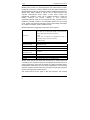
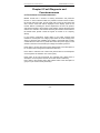
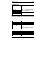
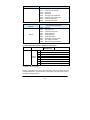
MD280 series basic configuration and function are as follows:
Five D1(DI can be selected as high-speed input port)
2×AI (AI2 can be selected as voltage or current input as
well as keyboard potentiometer reference.)
I/O terminal
2×DO
1×AO (can be selected as voltage/current input or
frequency output or DO output via FM.)
1×Relay output
Control Mode
V/F
Analog setup Mode
Straight line mode
MS speed
Be abled to realize 8S speed
Sipmle PLC
Swing
frequency
Be abled to realize 8S timing operation
and
fixed-length control
Communication Function
Available
Built-in 485 communication port
PID Control
Available
V/FMode
Linear V/F, Multi-point V/F, and Square V/F
MD280 series inverter has either built-in keyboard or external keyboard
connecting to the operational panel via the standard RJ45 interface (once
external keyboard is connected successfully, the built-in keyboard display
will disappear automatically, and vice versa), facilitating the commissioning
operation. All these features reflect the “Customer First” principle during the
process of designing MD series inverters.
This manual serves as the guide to MD 280 operation. This manual
II
MD280/MD280N User Manual
Preface
provides the user with issues and guidance on model selection, installation,
parameter setup, onsite commissioning, troubleshooting and routine repair
and maintenance. In order to use this series of inverters in a right manner,
please read this manual prior to operation, and keep this manual properly
for future reference. The customers with supporting equipment shall
distribute this manual together with the equipment to the final user.
Unpacking for Check:
Upon unpacking, please confirm:
1. If the model and inverter rated value on the nameplate are consistent as
the order. The box contains the equipment, certificate of conformity, user
manual and warranty card.
2. If the product is damaged during the transportation. If there is any
omission or damage, please contact our company or the supplier
immediately.
Use for the first time:
For the users who use this product for the first time, please read this
manual carefully prior to the use. If you have any doubt on certain functions
and performances, please consult our technical support personnel for help
so that you can use this product correctly.
This manual is subject to change without notice.
MD280 series inverter complies with the following international standards:
IEC/EN 61800-5-1: 2003 Safety Regulations on Speed Adjustable
Electrical Drive System;
IEC/EN 61800-3:2004 Speed Adjustable Electrical Drive System; Part III:
Electromagnetic Compatibility Standard and Specific Test Methods (It
complies with IEC/EN 61800-3 standard if this product is installed and used
properly according to Section 7.3.2 and Section 7.3.6).
III
Preface
IV
MD280/MD280N User Manual
Contact
Preface ..........................................................................................................I
Chapter 1 Safety and Precautions ...........................................................10
1.1 Safety precautions ............................................................10
1.2 Precautions....................................................................... 13
Chapter 2 Product Information............................................................ - 18 -
2.1 Designation Rules.........................................................- 18 2.2 Nameplate ....................................................................- 18 2.3 MD280 Series Inverter ..................................................- 19 2.4 Technical Specifications ................................................- 21 2.5 Physical Appearance and Dimensions of Mounting Hole- 25
2.6 Optional Parts ...............................................................- 33 2.7 Routine Repair and Maintenance of Inverter ................- 33 2.8 Instructions on Warranty of Inverter ..............................- 35 2.9 Guide to Model Selection..............................................- 36 2.10 Guide to Selection of Brake Components ...................- 37 Chapter 3 Mechanical and Electrical Installation .............................. - 42 -
3.1 Mechanical Installation..................................................- 42 3.2 Electrical Installation .....................................................- 46 Chapter 4 Operation and Display........................................................ - 62 -
4.1 Introduction to Operation and Display Interface............- 62 4.2 Description of Function Code Viewing and Modification
Method................................................................................- 63 4.3 Viewing Method of Status Parameter............................- 64 4.4 Password Setting..........................................................- 65 Chapter 5 Function Parameter Table .................................................. - 68 Chapter 6 Parameter Description...................................................... - 108 -
Group F0 Basic Function Group .......................................- 108 Group F1 Motor Parameter, V/F Control Parameter .........- 118 Group F2 Input Terminal ...................................................- 125 Group F3 Output Terminal ................................................- 138 Group F4 Start/Stop Control..............................................- 144 Group F5 Auxiliary Function..............................................- 153 Group F6 Process Control PID Function Parameters .......- 162 Group F7 Swing Frequency, Fixed Length and Counting .- 166 Group F8 MS Speed Function and Simple PLC Function.- 174 Group F9 Reserved ..........................................................- 179 Group FA Communication Parameters .............................- 179 Refer to MD280F Serial Communication Protocol for details......... - 179 -
Group FB Overload and Protection...................................- 179 Group C The Second Motor Parameter ................................ 189
Group FF Factory Default Parameters (Reserved) ............... 190
Group FP User password ..................................................... 190
Chapter 7 EMC (Electromagnetic Compatibility) ............................. - 194 -
7.1 Definition.....................................................................- 194 7.2 EMC Standard Description..........................................- 194 7.3 EMC Guide .................................................................- 194 Chapter 8 Fault Diagnosis and Countermeasures .......................... - 200 -
8.1 Fault Alarm and Countermeasures .............................- 200 8.2 Common Fault and Resolution ...................................- 213 Appendix Communication Protocol.................................................. - 215 -
MD280/MD280N User Manual
Preface
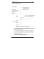
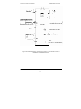
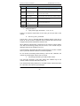
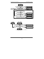
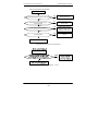
Connection to peripheral divices
Diagram for the connection to peripheral divices
z Do not install the capacitor or surge suppressor at the output
side of the inverter, otherwise it may cause inverter fault or capacitor
and surge suppressor damaged.
z The input/output (main circuit) of the Inverter contains harmonic
components, which may interfere with communications equipment of
the inverter accessories.Therefore, install anti-interference filter so
as to minimize interference.
z The details of peripheral equipments and accessories selection
refer to the manual of peripheral equipments.
7
MD280/MD280N User Manual
Safety and Precautions
Safety and Precautions
9
Safety and Precautions
MD280/MD280N User Manual
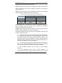
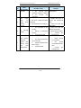
Chapter 1 Safety and Precautions
Safety definition:
In this manual, safety precautions are divided into two types below:
Danger arising due to improper operations may cause severe hurt or
even death.
Caution: Danger arising due to improper operations may cause
moderate hurt or light hurt or equipment damage.
During the installtion, commissioning and maintenance of the system,
plesase make sure to follow the safety precautions.Our company shall not
take liable for any damage or troubles resulting from wrong operations.
1.1 Safety precautions
1.1.1 Before Installation:
Danger
z Do not use the damaged inverter or inverter with missing parts.
Otherwise, there may be risk of injury.
z Please do not install when the packing list is inconsistent with
the real name.
Danger
z Carefully handled when loading, otherwise it may damage the
inverter.
z Please don’t use the damaged driver or missing parts inverter,
there may be risk of injury.
z Do not touch components of the control system, otherwise it will
cause static electricity.
1.1.2 During the Installation:
Danger
z Mount the inverter on incombustible surface like metal, and
keep away from flammable substances. Otherwise it may cause
fire.
z Do not loose the set screw of the equitment, especially the
MD280/MD280N User Manual
Safety and Precautions
screws marked in RED.
Caution
z Do not drop the lead wire stub or screw in the inverter.
Otherwise it may damage the inverter.
z Please install the driver in the place where there is no direct
sunlight or no vibratory.
z When more than two inverters are to be installed in one
cabinet, due attention shall be paid to the installation locations
(refer to Chapter 3 Mechanical and Electrical Installation to ensure
the heat sinking effect.
1.1.3 During wiring:
Danger
z Operation shall be performed by the professional engineering
technician. Otherwise there will be danger of electric shock.
z There shall be circuit breaker between the inverter and power
supply. Otherwise, there may be fire.
z Make sure the power is disconnected prior to the connection.
Otherwise there will be danger of electric shock.
z The earth terminal shall be earthed reliably. Otherwise there
may be danger of electric shock.
Danger
z Do not connect the input power cable to the output ends U, V
and W. Otherwise it may damage the inverter.
z Ensure the wiring meet the EMC requirements and the local
safety standard. The wire size shall be determined according to
the manual. Otherwise, accident may be caused!
z The brake resistor cannot be directly connected between the
DC bus terminals (+) and (-). Otherwise it may cause fire.
z The shiled wire should be used for encoder, and the shielding
layer shall be earthed reliably.
11
Safety and Precautions
MD280/MD280N User Manual
1.1.4 Before Power-on:
Caution
z Please confirm whether the power voltage class is consistent
with the rated voltage of the inverter and whether the I/O cable
connecting positions are correct, and check whether the external
circuit is short circuited and whether the connecting line is firm.
Otherwise it may damage the inverter.The cover must be well
closed prior to the inverter power-on. Otherwise electric shock
may be caused.
z The inverter is free from dielectric test because this test is
performed prior to the delivery. Otherwise accident may occur.
Danger
z The cover must be well closed prior to the inverter power-on.
Otherwise electric shock may be caused!
z Whether all the external fittings are connected correctly in
accordance with the circuit provided in this manual. Otherwise
accident may occur.
1.1.5 Upon Power-on
Danger
z Do not open the cover of the inverter upon power-on.
Otherwise there will be danger of electric shock!
z Do not touch the inverter and its surrounding circuit with wet
hand. Otherwise there will be danger of electric shock.
z Do not touch the inverter terminals (including control terminal).
Otherwise there will be danger of electric shock.
z At power-on, the inverter will perform the security check of the
external heavy-current circuit automatically. Thus, at this time
please do not touch the terminals U, V and W, or the terminals of
motor, otherwise there will be danger of electric shock.
Danger
MD280/MD280N User Manual
Safety and Precautions
z If the parameter identification is required, pay attention to the
danger of injury arising from the rotating motor. Otherwise
accident may occur.
z Do not change the factory settings at will. Otherwise it may
damage the equipment.
1.1.6 During the operation:
Danger
z Do not touch the fan or discharge resistor to sense the
temperature. Otherwise, you may get burnt.
z Detection of signals during the operation shall only be
conducted by qualified technician. Otherwise, personal injury or
equipment damage may be caused.
Caution
z During the operation of the inverter, keep items from falling
into the equipment. Otherwise, it may damage the equipment.
z Do not start and shut down the inverter by connecting and
disconnecting the contactor. Otherwise, it may damage the
equipment.
1.1.7 During Repair
Danger
z Do not repair and maintain the equipment with power
connection. Otherwise there will be danger of electric shock.
z Be sure to conduct repair and maintenance after the charge
LED indictor of the inverter is OFF. Otherwise, the residual
charge on the capacitor may cause personal injury.
z The inverter shall be repaired and maintained only by the
qualified person who has received professional training.
Otherwise, it may cause personal injury or equipment damage.
z Carry out parameter setting after replacing the inverter, all the
plug-ins must be plug and play when power outage.
1.2 Precautions
1.2.1 Motor Insulation Inspection
13
Safety and Precautions
MD280/MD280N User Manual
When the motor is used for the first time, or when the motor is reused after
being kept, or when periodical inspection is performed, it shall conduct
motor insulation inspection so as to avoid damaging the inverter because
of the insulation fault of the motor windings. The motor wires must be
disconnected from the inverter during the insulation inspection. It is
recommended to use the 500V megameter, and the insulating resistance
measured shall be at least 5MΩ.
1.2.2 Thermal Protection of the Motor
If the ratings of the motor does not match those of the inverter, especially
when the rated power of the inverter is higher than the rated power of the
motor, the relevant motor protection parameters in the in the inverter shall
be adjusted, or thermal relay shall be mounted to protect the motor.
1.2.3 Running with Frequency higher than Standard Frequency
This inverter can provide output frequency of 0Hz to 300Hz. If the user
needs to run the inverter with frequency of more than 50Hz, please take the
resistant pressure of the mechanical devices into consideration.
1.2.4 Vibration of Mechanical Device
The inverter may encounter the mechanical resonance point at certain
output frequencies, which can be avoided by setting the skip frequency
parameters in the inverter.
1.2.5 Motor Heating and Noise
Since the output voltage of inverter is PWM wave and contains certain
harmonics, the temperature rise, noise and vibration of the motor will be
higher than those when it runs at standard frequency.
1.2.6 Voltage-sensitive Device or Capacitor Improving Power Factor
at the Output Side
Since the inverter output is PWM wave, if the capacitor for improving the
power factor or voltage-sensitive resistor for lightning protection is mounted
at the output side, it is easy to cause instantaneous over current in the
inverter, which may damage the inverter. It is recommended that such
devices not be used.
1.2.7 Switching Devices like Contactors Used at the Input and Output
terminal
MD280/MD280N User Manual
Safety and Precautions
If a contactor is installed between the power supply and the input terminal
of the inverter, it is not allowed to use the contactor to control the
startup/stop of the inverter. If use of such contactor is unavoidable, it shall
be used with interval of at least one hour. Frequent charge and discharge
will reduce the service life of the capacitor inside the inverter. If switching
devices like contactor are installed between the output end of the inverter
and the motor, it shall ensure that the on/off operation is conducted when
the inverter has no output. Otherwise the modules in the inverter may be
damaged.
1.2.8 Use under voltage rather than rated voltag
If the MD series inverter is used outside the allowable working voltage
range as specified in this manual, it is easy to damage the devices in the
inverter. When necessary, use the corresponding step-up or step-down
instruments to change the voltage.
1.2.9 Change Three-phase Input to Two-phase Input
It is not allowed to change the MD series three-phase inverter into
two-phase one. Otherwise, it may cause fault or damage to the inverter.
1.2.10 Lightning Impulse Protection
The series inverter has lightning over current protection device, and has
certain self-protection capacity against the lightning. In applications
where lightning occurs frequently, the user shall install additional protection
devices at the front-end of the inverter.
1.2.11 Altitude and Derating
In areas with altitude of more than 1,000 meters, the heat sinking effect of
the inverter may turn poo rer due to rare air. Therefore, it needs to derate
the inverter for use. Please contact our company for technical consulting in
case of such condition.
1.2.12 Certain Special Use
If the user needs to use the inverter with the methods other than the
recommended wiring diagram in this manual, such as shared DC bus,
please consult our company.
1.2.13 Cautions of Inverter Disposal
The electrolytic capacitors on the main circuit and the PCB may explode
15
Safety and Precautions
MD280/MD280N User Manual
when they are burnt.Emission of toxic gas may be generated when the
plastic parts are burnt. Please dispose the inverter as industrial wastes.
1.2.14 Adaptable Motor
1) The standard adaptable motor is four-pole squirrel-cage asynchronous
induction motor. If such motor is not available, be sure to select adaptable
motors in according to the rated current of the motor. In applications where
drive permanent magnetic synchronous motor is required, please consult
our company.
2) The cooling fan and the rotor shaft of the non-frequency-conversion
motor adopt coaxial connection. When the rotating speed is reduced, the
heat sinking effect will be poorer. Therefore, a powerful exhaust fan shall
be installed, or the motor shall be replaced with frequency conversion
motor to avoid the overheating of the motor.
3) Since the inverter has built-in standard parameters of the adaptable
motors, it is necessary to perform motor parameter identification or modify
the default values so as to comply with the actual values as much as
possible, or it may affect the running effect and protection performance;
4) The short circuit of the cable or motor may cause alarm or explosion of
the inverter. Therefore, please conduct insulation and short circuit test on
the newly installed motor and cable. Such test shall also be conducted
during routine maintenance. Please note that the inverter and the test
part shall be completely disconnected during the test.
MD280/MD280N User Manual
Safety and Precautions
Product Information
17
Product Information
MD280/MD280N User Manual
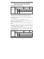
Chapter 2 Product Information
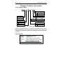
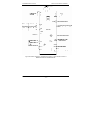
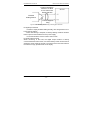
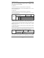
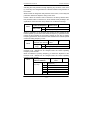
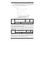
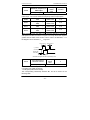
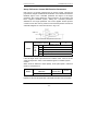
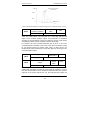
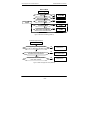
2.1 Designation Rules
MD280N
T 7.5G B / 11P B
Brake Unit
Null
None
B
Including Brake Unit
Inverter Series
11kW P model
MD280
Corresponding Relationship
MD280N
Voltage Level
S
Single Phase 220
T
Three Phase 380
Mark
0.4 0.7 …… 400 450
Motor Power
0.4 0.75 …… 400 450
Brake Unit
Null
None
B
Including Brake Unit
7.5kW G model
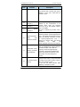
Fig.2-1 Designation Rules
Caution: The MD280N series is an upgrade of the MD280 series in terms of
external appearance and structural design. Except for special notes on the
MD320N, all the following information is appropriate for the MD320N series
of products.
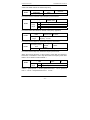
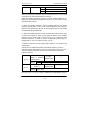
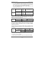
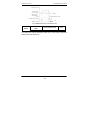
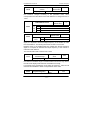
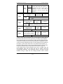
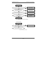
2.2 Nameplate
MODEL:
POWER:
INPUT:
OUTPUT:
S/N:
MD280NT7.5GB/11PB
7.5kW-11kW
3PH AC380V 26A 50Hz/60Hz
3PH AC0V380V 25A 0Hz~630Hz
Barcode
Shenzhen Inovance Technology Co.,Ltd.
Fig.2-2 Nameplate
MD280/MD280N User Manual
Product Information
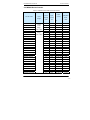
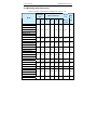
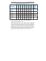
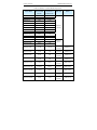
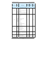
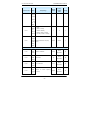
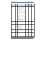
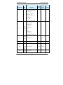
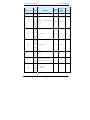
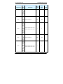
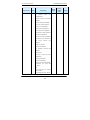
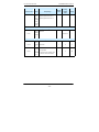
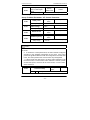
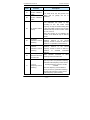
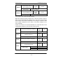
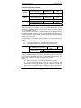
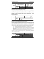
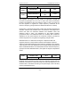
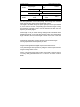
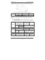
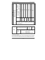
2.3 MD280 Series Inverter
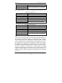
Table 2-1 MD280 Inverter Model and Technical Data
Rated
Inverter model
Input
Voltage
Power
Input
capacity
current
(kVA)
(A)
Output
current
Adaptable
Motor
(kW)
(A)
MD280S0.4G
Single
1.0
5.4
2.3
0.4
MD280S0.7G
Phase
1.5
8.2
4.0
0.75
MD280S1.5G
Range:
3.0
14.0
7.0
1.5
MD280S2.2G
-15% to 20%
4.0
23.0
9.6
2.2
MD280T0.7G
Three-Phase
1.5
3.4
2.1
0.75
MD280T1.5G
Range:
3.0
5.0
3.8
1.5
MD280T2.2G
-15% to 20%
4.0
5.8
5.1
2.2
8.9
14.6
9.0/13.0
3.7/5.5
MD280T3.7G/5.5P
MD280T5.5G/7.5P
11.0
20.5
13.0/17.0
5.5/7.5
MD280T7.5G/11P
17.0
26.0
17.0/25.0
7.5/11
MD280T11G/15P
21.0
35.0
25.0/32.0
11/15
MD280T15G/18.5P
24.0
38.5
32.0/37.0
15/18.5
MD280T18.5G/22P
30.0
46.5
37.0/45.0
18.5/22
MD280T22G/30P
40.0
62.0
45.0/60.0
22/30
MD280T30G/37P
57.0
76.0
60.0/75.0
30/37
MD280T37G/45P
69.0
92.0
75.0/91.0
37/45
MD280T45G/55P
85.0
113.0
91.0/112.0
45/55
MD280T55G/75P
114.0
157.0
112.0/150.0
55/75
MD280T75G/90P
134.0
180.0
150.0/176.0
75/90
MD280T90G/110P
160.0
214.0
176.0/210.0
90/110
MD280T110G/132P
192.0
256.0
210.0/253.0
110/132
MD280T132G/160P
231.0
307.0
253.0/304.0
132/160
MD280T160G/200P
250.0
385.0
304.0/377.0
160/200
MD280T200G/220P
280.0
430.0
377.0/426.0
200/220
MD280T220G/250P
355.0
468.0
426.0/465.0
220/250
MD280T250G/280P
396.0
525.0
465.0/520.0
250/280
MD280T280G/315P
445.0
590.0
520.0/585.0
280/315
MD280T315G/355P
500.0
665.0
585.0/650.0
315/355
- 19 -
Product Information
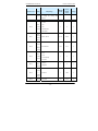
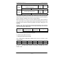
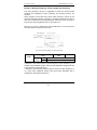
MD280/MD280N User Manual
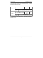
Rated
Output
Power
Input
capacity
current
(kVA)
(A)
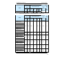
MD280T355G/400P
565.0
785.0
650.0/725.0
355/400
MD280T400G/450P
630.0
883.0
752.0/820.0
400/450
Inverter model
Input
Voltage
current
Adaptable
Motor
(kW)
(A)
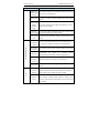
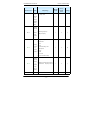
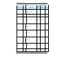
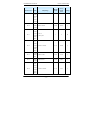
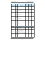
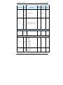
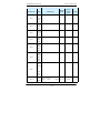
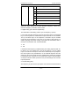
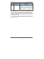
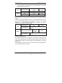
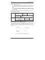
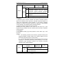
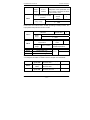
Table 2-2 MD280 Inverter Model and Technical Data
Inverter model
MD280NS0.4
MD2800NS0.7
MD280NS1.5
Input
Current
Output
Current
Adaptable
Motor
(kW)
Input
Voltage
Power
Supply
Single
Phase
Range:
-15% to
20%
1.0
5.4
2.3
0.4
1.5
8.2
4.0
0.75
1.5
3.0
14.2
7.0
4.0
23.0
9.6
2.2
MD280NT0.7
1.5
3.4
2.1
0.75
MD280NT1.5
3.0
5.0
3.8
1.5
MD280NT2.2
4.0
5.8
5.1
2.2
MD280NT3.7G/5.5P
5.9
14.6
9.0/13.0
3.7
MD280NT5.5G/7.5P
8.9
20.5
13.0/17.0
5.5
MD280NT7.5G/11P
11.0
26.0
17.0/25.0
7.5
17.0
35.0
25.0/32.0
11.0
21.0
38.5
32.0/37.0
15.0
30.0
46.5
37.0/45.0
18.5/22
MD280NT22G/30P
40.0
62.0
45.0/60.0
22/30
MD280NT30G/37P
57.0
76.0
60.0/75.0
30/37
MD280NT37G/45P
69.0
92.0
75.0/91.0
37/45
MD280NT45G/55P
85.0
113.0
91.0/112.0
45/55
MD280NT55G/75P
114.0
157.0
112.0/150.0
55/75
MD280NS2.2
MD280NT11G/11P
MD280NT15G/18.5P
MD280NT18.5G/22P
Three
Phase
Range:
-15% to
20%
MD280/MD280N User Manual
Product Information
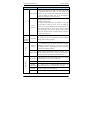
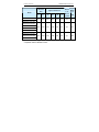
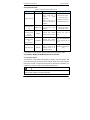
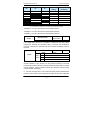
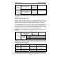
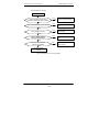
2.4 Technical Specifications
Table 2-3 MD320 Inverter Technical Specifications
Item
Specifications
Maximum
frequency
Carrier
frequency
Input
frequency
resolution
Control mode
630Hz
0.5k to 16kHz; the carrier frequency will be automatically
adjusted according to the load characteristics.
Digital setting: 0.01Hz
Analog setting: maximum frequency ×0.1%
V/F control
Vector flux control
Startup torque 150%
Speed
adjustment
1:50
Basic function
range
Speed
stabilization
±1%
precision
Overload
G model: 150% rated current 60s;
capacity
P model: 130% rated current 60s;
Torque hoist Automatic torque hoist; manual torque hoist 0.1% to 30.0%
V/F curve
Linear V/F, Multi-point V/F, and Square V/F
Speed-up and Straight line or S curve speed-up and speed-down mode;
Speed-down Two kinds of speed-up and speed-down time; Speed-up and
curve
DC brake
Jog control
speed-down time ranges between 0.0s to 3000.0min.
DC brake frequency: 0.00Hz to maximum frequency; brake
time: 0.0s to 36.0s, and brake current value: 0.0% to 100.0%.
Jog
frequency
range:
0.00Hz
to
50.00Hz;
jog
speed-up/speed-down time: 0.0s to 3000.0s.
- 21 -
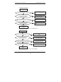
Product Information
MD280/MD280N User Manual
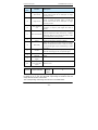
Item
Specifications
Simple PLC
and MS speed
running
Built-in PID
It can realize a maximum of 8 segments speed running via the
built-in PLC or control terminal.
It is easy to realize process-controlled close loop control
system.
(AVR)Auto
voltage
regulation
It can keep constant output voltage automatically in case of
change of mains voltage.
(AVR)
Stall over
It can limit the torque automatically and prevent frequent over
current control current tripping during the running process.
Quick current Minimize the over-current fault, protect normal operation of the
limit
Peripherals
self-detection
inverter
It can conduct safety detections on the peripherals upon
power-on, including earth and short circuit detections.
upon power-on
Individua-lized function
Shared DC
It can realize the function that multiple inverters share the DC
bus function bus.
MF.K key
Programmable
key:
Select
the
command
channel
switching/forward and reverse rotations/jog operation.
Textile swing
frequency
Multiple triangular-wave frequency control function
control
Timing control
Running
command
channel
Timing control function: Setting time range between 0h to
65535 h.
Three types of channels: operation panel reference, control
terminal reference and serial communication port reference.
These channels can be switched in various modes.
Run
There are totally eight types of frequency sources, such as
Frequency
digital reference, analog voltage reference, analog current
source
reference, pulse reference, MS speed, PLC, PID, and serial
port reference.
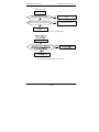
MD280/MD280N User Manual
Item
Product Information
Specifications
There are five digital input terminals, one of which can be used
as high-speed pulse input. There are two analog input
Input terminal terminals. AI1 can be used only as voltage input, while AI2 can
be used as voltage or current input. (It can be selected to
keyboard potentiometer input via the jumper.)
Two digital output terminals
One relay output terminal
One analog output terminal (can be expanded to two), with
Output
terminal
optional 0//4mA to 20mA or 0/2V to 10V. It can realize the
output of such physical parameters as setting frequency and
output frequency,while via FM to output 0kHz to 50kHz
square-wave signal. DO3 can also be set to open-collector
output. (AO, FM, DO3 share a channel, making a distinction
via the function selection.)
Display
and
Keyboard
LED display
The machine has the LED keyboard,and realize parameter
settings, status monitoring function
Operation
It can implement power-on motor short-circuit detection,
Others
Protection
input/output phase loss protection, over current protection,
function
over voltage protection, under voltage protection, overheating
protection and overload protection.
Optional external keyboard(which has two selection ,one is
Optional parts with the potentiometer,the other is without the potentiometer),
braking components and external keyboard cable,etc.
Using place
Indoor, and be free from direct sunlight, dust, corrosive gas,
combustible gas, oil smoke, vapor, drip or salt.
Environment
Altitude
1000m, derated when above 1000m
Ambient
-10 ℃ Celsius to +40 ℃ Celsius (Derated when used in the
temperature ambient temperature of 40 ℃ Celsius to 50 ℃ Celsius)
Humidity
Less than 95%RH, without condensing
Vibration
Less than 5.9 m/s2(0.6g)
- 23 -
Product Information
Item
Storage
temperature
MD280/MD280N User Manual
Specifications
-20 Celsius to +60 Celsius
MD280/MD280N User Manual
Product Information
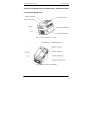
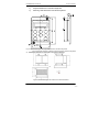
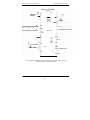
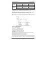
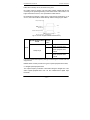
2.5 Physical Appearance and Dimensions of Mounting Hole
2.5.1Product Appearance
Upper Cover Plate
Operation Panel
Lower Cover Plate
I/O Port
Bottom Mounting Hole
Fan
Inverter Nameplate
Fig.2- 1 Physical Appearance of Inverter
Fig.2- 2 Inverter Appearance of MD280N
- 25 -
Product Information
MD280/MD280N User Manual
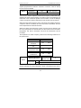
Fig.2-5 Schematic Diagram for Physical Dimensions and Mounting Dimensions of
D
B
H
H1
MD280S0.4G to MD280T15G/18.5P
A
W
Fig.2-6 Schematic Diagram for Physical Dimensions and Mounting Dimensions of
MD280T18.5G/22P to MD280T400G/450P
MD280/MD280N User Manual
Product Information
Fig.2-3 Schematic Diagram for Physical Dimensions and Mounting Dimensions of
MD280NT18.5G/22P to MD280NT400G/450P
- 27 -
Product Information
MD280/MD280N User Manual
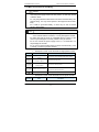
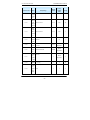
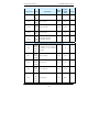
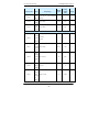
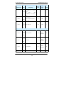
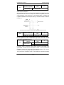
2.5.2 Mounting Hole Dimensions
Table 2-3 Mounting Hole Dimensions of MD280 Series Inverter(mm)
Mounting
Diamet
Weig
Physical Dimension
Hole
Model
A
er of
B
H
H1
W
D
Mounti
ht
(kg)
ng Hole
MD280S0.4G
MD280S0.7G
MD280S1.5G
MD280S2.2G
113
172
182
/
123
145
φ5.4
1.1
147
236
246
/
158
165
φ5.4
2.5
150
335
322
348
224
177
Φ6
7
235
447
430
460
285
220
φ6.5
20
250
598
573
620
380
262
φ10
34
343
678
660
700
473
307
φ10
47
449
905
880
930
579
375
φ10
90
320
1168
1049
1192
440
334
φ10
98
420
1030
983
1060
650
377
φ12
130
520
1300
1203
1358
800
400
φ14
200
MD280T0.7G
MD280T1.5G
MD280T2.2G
MD280T3.7G/5.5P
MD280T5.5G/7.5P
MD280T7.5G/11P
MD280T11G/15P
MD280T15G/18.5P
MD280T18.5G/22P
MD280T22G/30P
MD280T30G/37P
MD280T37G/45P
MD280T45G/55P
MD280T55G/75P
MD280T75G/90P
MD280T90G/110P
MD280T110G/132P
MD280T132G/160P
MD280T160G/200P
MD280T200G/220P
MD280T220G/250P
MD280T250G/280P
MD280T280G/315P
MD280T315G/355P
MD280T355G/400P
MD280/MD280N User Manual
Product Information
Mounting
Diamet
Weig
Physical Dimension
Hole
Model
A
er of
B
H
H1
W
D
Mounti
ht
(kg)
ng Hole
MD280T400G/450P
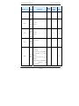
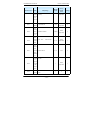
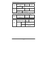
Table 2-5 Mounting Hole Dimensions of MD280N Series Inverter(mm)
Mounting
Diamet
Weig
Physical Dimension
Hole
er of
Model
Mounti
A
B
H
H1
W
D
ht
(kg)
ng Hole
MD280NS0.4G
MD280NS0.7G
MD280NS1.5G
MD320NS2.2G
113
172
186
/
125
164
Φ5.0
1.1
148
236
248
/
160
183
φ5.0
2.5
190
305
322
208
192
φ6
6.5
235
447
432
463
285
228
φ6
20
260
580
549
600
385
265
φ10
32
343
678
660
700
473
307
φ10
47
MD280NT0.7G
MD280NT1.5G
MD280NT2.2G
MD280NT3.7G
MD280NT5.5G/7.5P
MD280NT7.5G/11P*
MD280NT11G/15P*
*
MD280NT15G/18.5P
/
MD280NT18.5G/22P*
MD280NT22G/30P*
MD280NT30G/37P*
MD280NT37G/45P*
MD280NT45G/55P*
*
MD280NT55G/75P
MD280NT75G/90P
MD280NT90G/110P
- 29 -
Product Information
MD280/MD280N User Manual
Mounting
Diamet
Weig
Physical Dimension
Hole
er of
Model
Mounti
A
B
H
H1
W
D
ht
(kg)
ng Hole
MD280NT110G/132P
MD280NT132G/160P
449
905
880
930
579
375
φ10
90
420
1030
983
1060
650
377
φ12
130
520
1300
1203
1358
800
400
φ14
200
MD280NT200G/220P
MD280NT220G/250P
MD280NT250G/280P
MD280NT280G/315P
MD280NT315G/355P
MD280NT355G/400P
MD280NT400G/450P
Caution: The mounting hole dimension of MD280 series inverter is not
compatible with the MD280 inverter.
MD280/MD280N User Manual
1)
Physical Dimensions of External Keyboard
2)
Mounting Hole Dimensions of External Keyboard
Product Information
Fig.2-8 Schematic Diagram for Physical Dimensions of External Keyboard
Fig.2-9 Schematic Diagram for Mounting Hole Dimension of External Keyboard
3)Schematic Diagram for Dimension of External Reactor
Fig.2-10 Schematic Diagram for Dimensions of External Reactor
- 31 -
Product Information
MD280/MD280N User Manual
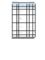
Table 2-6 External Reactor Dimension Table (mm)
Connectio
Moun
Inverter Mode
A
B
C
D
E
F
G
n Diameter
ting
Hole of
Hole
Copper
Medal
MD280T75G/90P
、
90G/110P
、
160
190
125
161
192
255
195
10*15
φ12
160
190
125
161
192
255
195
10*15
φ12
190
230
93
128
250
325
200
13*18
φ15
190
230
93
128
250
325
200
13*18
φ15
224
250
135
165
260
330
235
12*20
φ14
110G/132P
MD280T132G/160P、
160G/200P
MD280T200G/220P、
220G/250P
MD280T250G/280P、
280G/315P
MD280T315G/355P、
355G/400P
、
400G/450P
Caution: Non-standard may be ordered for special requirements.
*External DC reactor installation mode:
MD280 series inverter of more than 75kW produced by Inovance all
employs standard external DC reactor, which is packed in independent
wooden box and delivered together with the inverter. When mounting the
inverter, the user needs to remove the short circuit bus between the
terminals P and (+) of the main circuit of the inverter and then connect the
DC reactor between P and (+). There is no polarity between the reactor
terminal and the inverter terminals P and (+). After the DC reactor is
mounted, the short circuit bus between P and (+) will not be used.
MD280/MD280N User Manual
Product Information
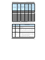
2.6 Optional Parts
Table 2-7 Optional Parts of MD280 Inverter
Name
Model
Function
Standard
built-in
brake
inverter
Built-in brake unit
Remark
configured
unit
of
of
below
15G/18.5P
Built-in brake unit of
inverter of 18.5G/22P to
Built-in brake unit of
three phase slave
0.75kW to 15G/18.5P is
standard configuration.
30G/37P
External brake
unit
MDBU-70-B
External built-in brake
55G/75P or above is
unit of inverter of over
required, it can employ
37G/45P
the parallel mode.
External LED
operation panel
without
MDKE2
External
LED
display
and operation keyboard
External A12 input is
used
potentiometer
External LED
operation panel
with
MD28KE2
External
LED
display
and operation keyboard
potentiometer
Take the potentiometer
on the keyboard as AI2
input
Standard 8-core network
Extended cable
MDCAB
cable is used as the
Standard Configuration
extended cable for the
of 3m
external keyboard.
If you need such option parts, please specify when placing the order.
2.7 Routine Repair and Maintenance of Inverter
2.7.1 Routine Repair
The influence of the ambient temperature, humidity, dust and vibration will
cause the burning of the devices in the inverter, which may cause potential
fault of the inverter or reduce the service life of the inverter. Therefore, it is
necessary to carry out daily and periodical maintenance.
注意
Caution
Repair or maintenance cannot be performed right after power-off as
there is high voltage on the filter capacitor.
- 33 -
Product Information
MD280/MD280N User Manual
注意
Caution
The repair or maintenance can be conducted only after the charge LED
is OFF and the bus voltage is measured to be less than 36V with
multimeter.
Routine inspection items include:
1)
Whether there is any abnormal change in the running
sound of the motor
2)
Whether the motor has vibration during the running
3)
Whether there is
environment of the inverter
any
change
to
the
installation
4) Whether the inverter cooling fan works normally
5) Whether the inverter has over temperature
Routine cleaning:
The inverter shall be kept clean.
The dust on the surface of the inverter shall be effectively removed, so as
to prevent the dust falling into the inverter, especially the metal dust.
The oil stain on the inverter cooling fan shall be effectively removed.
2.7.2 Periodical inspection
Please perform periodic inspection on the places where the inspection is a
difficult thing.
Periodic inspection Items include:
1)
Check and clean the air duct periodically;
2)
Check if the screws are loosened;
3)
Check if the inverter is corroded;
4)
Check if the wire connector has arc signs;
5)
Main circuit insulation test.
Reminder: When using the megameter (DC 500V megameter
recommended) to measure the insulating resistance, the main circuit shall
be disconnected with the inverter. Do not use the insulating resistance
MD280/MD280N User Manual
Product Information
meter to control the insulation of the circuit. It is not necessary to conduct
the high voltage test (which has been completed upon delivery).
2.7.3 Replacement of Vulnerable Parts for Inverter
The vulnerable parts of the inverter include cooling fan and filter electrolytic
capacitor, whose life depends on the operating environment and
maintenance status. Common service life:
Part name
Life time
Fan
2 to 3 years
Electrolytic
capacitor
4 to 5 years
The user can determine the term for replacement according to the running
time.
1) Cooling fan
Possible causes for damage: bearing wearing and blade aging.
Criteria: Whether there is crack on the blade and whether there is abnormal
vibration noise upon startup.
2) Possible causes for damage of filter electrolytic capacitor: Poor
input source quality, high ambient temperature, frequent load jumping
and burning electrolyte.
Criteria: Whether there is liquid leakage, whether the safe valve has
projected, measure the static capacitance, and measure the insulating
resistance.
2.7.4 Storage of Inverter
Attention shall be paid to the following points for the temporary and
long-term storage of the inverter:
1) Place the inverter back into the packing box following the original
package
2) Long-term storage will degrade the electrolytic capacitor. The product
shall be powered up once every 2 years, and the power-up time shall be no
less than 5 hours. The input voltage shall be increased slowly to the rated
value with the regulator.
2.8 Instructions on Warranty of Inverter
Free warranty only applies to the inverter itself.
- 35 -
Product Information
MD280/MD280N User Manual
1. Our company will provide 18-month warranty (starting from the
leave-factory date as indicated on the barcode) for the fault or damage
under normal use conditions. If the equipment has been used for over 18
months, reasonable repair expenses will be charged.
2. Reasonable repair expenses will be charged for the following situations
within 18 months:
1)
The equipment is damaged because the user fails to
comply with the requirements of the user’s manual;
2)
Damage caused by fire, flood and abnormal voltage;
3)
Damage caused when the inverter is used for abnormal
function.
The service expenses will be calculated according to the standard of the
manufacturer. If there is any agreement, the agreement shall prevail.
2.9 Guide to Model Selection
When selecting inverter, firstly make clear the details regarding the
technical requirements for variable frequency speed adjustment of the
system, applications of inverter and load characteristics and take into
overall consideration the adaptable motor, output voltage, rated output and
other factors, and then select the model meeting your requirements and
determine the running mode.
The basic principle is that the rated load current of the motor cannot
exceed the rated current of the inverter. Generally, the model is selected in
accordance with the capacity of the supporting motor as specified in the
user’s manual, with attention to the comparison of rated currents between
the motor and the inverter. The overload capacity of the inverter makes
sense only for the startup and brake processes. If instantaneous overload
occurs in the running process, the load speed will vary. If there are higher
requirements for the speed precision, please consider a larger one, or
select MD300/320 vector control series.
Fan and pump type: It has lower requirements for the overload capacity.
Since the load torque is proportional to the square of the speed, the load is
slightly light when it is running at low speed (except Roots fan).
Furthermore, this type of load has no special requirements for the precision
of the rotation velocity, thus square torque V/F is selected.
Constant torque load: Most loads have constant torque characteristics but
low requirements in terms of precision of rotation
MD280/MD280N User Manual
Product Information
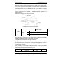
2.10 Guide to Selection of Brake Components
It means selection of data. The user can select different resistance and
power according to the actual situation (but the resistance shall not be
lower than the recommended value in the table, while power can be higher).
The selection of brake resistor depends upon the power of the motor in the
actual application system and correlates with the system inertia,
deceleration time and energy of position load, which shall be performed
according to the actual situation.The higher the system inertia is, the
shorter the deceleration time required is, while more frequent the brake is,
leading to that the brake resistor needs higher power and lower resistance.
2.10.1Selection of Resistance Vlaue
Renewable electric energy consumption is almost the braking resistor
when braking.
According to the formula: U*U/R=Pb,
U refers to stable Braking system of Brake voltage. (Different system has
different brake voltage. Generally select 700V for the system 380VAC).
Pb represents the Braking power.
2.10.2 Selection of Braking Resistor Power
Theoretically, braking resistor Power is consistent with braking Power.But
the derating is 70%.
According to the formula: 0.7*Pr=Pb*D.
Pr refers to the resistor Power.
D refers to braking frequency. (The regeneration process in the proportion
of the entire working process).For example, the braking frequency of
elevator is between 20%~30%, the winding and unwinding is between 20%
~30%.The centrifuge is between 50%~60%, Occasional brake load is 5%.
The General selection is 10%.
- 37 -
Product Information
MD280/MD280N User Manual
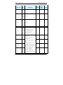
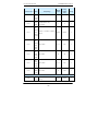
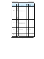
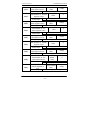
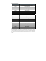
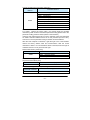
Table 2-5 Selection of Inverter Brake Components
Recommended
Inverter Model
Recommended
Power of Brake
Resistance of
Resistor
Brake Resistor
80W
≥200Ω
MD280S0.7G
80W
≥150Ω
MD280S1.5G
100W
≥100Ω
MD280S2.2G
100W
≥70Ω
MD280T0.7G
150W
≥300Ω
MD280T1.5G
150W
≥220Ω
Built-in as
MD280T2.2G
250W
≥200Ω
standard
MD280T3.7G/5.5P
400W
≥90Ω
MD280T5.5G/7.5P
500W
≥65Ω
MD280T7.5G/11P
800W
≥43Ω
MD280T11G/15P
1000W
≥32Ω
MD280T15G/18.5P
1300W
≥25Ω
MD280T18.5G/22P
1500W
≥22Ω
Built-in as
MD280T22G/30P
2500W
≥16Ω
optional
MD280T30G/37P
2500W
≥16Ω
MD280T37G/45P
3.7 kW
≥16.0Ω
MD280T45G/55P
4.5 kW
≥16Ω
MD280T55G/75P
5.5 kW
≥8Ω
7.5 kW
≥8Ω
4.5 kW×2
≥8Ω×2
MD280T110G/132P
5.5 kW×2
≥8Ω×2
MD280T132G/160P
6.5 kW×2
≥8Ω×2
MD280T160G/200P
16kW
≥2.5Ω
MD280T200G/220P
20 kW
≥2.5Ω
MD280S0.4G
MD280T75G/90P
MD280T90G/110P
Brake Unit
Externally
connected
Externally
connected
Externally
connected
Externally
connected
Externally
connected
Externally
connected
Externally
connected
Externally
connected
Externally
connected
Rmarks
MDBU-35-B
MDBU-35-B
MDBU-70-B
MDBU-70-B
MDBU-70-B×2
MDBU-70-B×2
MDBU-70-B×2
MDBU-210-B
MDBU-210-B
MD280/MD280N User Manual
Product Information
Recommended
Inverter Model
Recommended
Power of Brake
Resistance of
Resistor
Brake Resistor
MD280T220G/250P
22 kW
≥2.5Ω
MD280T250G/280P
12.5 kW×2
≥2.5Ω×2
MD280T280G/315P
14kW×2
≥2.5Ω×2
MD280T315G/355P
16kW×2
≥2.5Ω×2
MD280T355G/400P
17kW×2
≥2.5Ω×2
MD280T400G/450P
14 kW×3
≥2.5Ω×3
Brake Unit
Externally
connected
Externally
connected
Externally
connected
Externally
connected
Externally
connected
Externally
connected
Rmarks
MDBU-210-B
MDBU-210-B×2
MDBU-210-B×2
MDBU-210-B×2
MDBU-210-B×2
MDBU-210-B×3
Caution: ×2 refers to two braking units paralleled with their respective brake
resistor; the meaning of ×3 is the same with ×2.
- 39 -
Product Information
MD280/MD280N User Manual
MD280/MD280N User Manual
Product Information
Mechanical and Electrical Installation
41
Mechanical and Electrical Installation
MD280/MD280N User Manual
Chapter 3 Mechanical and Electrical
Installation
3.1 Mechanical Installation
3.1.1 Installation environment:
1) Ambient temperature: The ambient temperature exerts great influences
on the service life of the inverter and is not allowed to exceed the allowable
temperature range (-10 ℃ Celsius to 50 ℃ Celsius).
2) The inverter shall be mounted on the surface of incombustible articles,
with sufficient spaces nearby for heat sinking. The inverter is easy to
generate large amount of heat during the operation. The inverter shall be
mounted vertically on the base with screws.
3) The inverter shall be mounted in the place without vibration or with
vibration of less than 0.6G, and shall be kept away from such equipment as
punching machine.
4) The inverter shall be mounted in locations free from direct sunlight, high
humidity and condensate.
5) The inverter shall be mounted in locations free from corrosive gas,
explosive gas or combustible gas.
The inverter shall be mounted in locations free from oil dirt, dust, and
metal powder.
6)
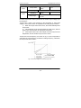
Fig.3-1MD280 Inverter Installation Diagram
- 42 -
MD280/MD280N User Manual
Mechanical and Electrical Installation
Installation Diagram of Upper and Down Parts
Caution: When the inverter power is not higher than 22kW, the A size can be
omitted. When the inverter power is higher than 22kW, the A size shall be
higher than 50mm.
Caution: When performing up-down installation of inverter, please install the
thermal insulating guide plate as shown in the diagram.
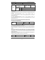
Table.3-1 Schematic Diagram for Installation of MD280 Inverter
Power Level
Mounting Dimension
B
A
≤15kW
≥100mm
No requirements
18.5kW—30kW
≥200mm
≥50mm
≥37kW
≥300mm
≥50mm
Caution: When the inverter power is no more than 18.5G/22P, dimension A
can be neglected. When the inverter power is higher than 18.5G/22P,
dimension A shall be higher than 50mm.
Caution: When performing up-down installation of inverter, please install the
thermal insulating guide plate as shown in the diagram.
Heat sinking shall be taken into account during the installation. Attention shall
be paid to the following items:
1)
Install the inverter vertically so that the heat may be expelled from
the top.However, the equipment cannot be installed upside down. If there
are multiple inverters in the cabinet, parallel installation is better. In the
applications where up-down installation is required, please install the
thermal insulating guide plate referring to the schematic diagrams for
standalone installation and up-down installation.
2)
The mounting space shall be as indicated as the above diagrams,
so as to ensure the heat sinking space of the inverter. However, the heat
sinking of other devices in the cabinet shall also be considered.
3)
The installation bracket must be made of flame retardant
materials.
4)
In the applications where there are metal powders, it is
recommended to install the radiator outside the cabinet. In this case, the
- 43 -
Mechanical and Electrical Installation
MD280/MD280N User Manual
space inside the sealed cabinet shall be large as much as possible.
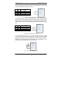
Lower cover removable and installation: MD280 series inverter of below
15G/18.5P employs the plastic enclosure. Refer to Fig.3-2 for the removal of
the lower cover of the plastic enclosure. Push out the hook inside of the lower
cover with tools.
Hooker
Lower Cover Plate
Align with the Internal Side
and Press with Forces
Hook Slot
Fig.3-2 Removal of Lower Cover of the Plastic Enclosure
- 44 -
MD280/MD280N User Manual
Mechanical and Electrical Installation
MD series inverters of above 18.5G/22P employ sheet-metal enclosures.
Refer to Fig.3-3 for the removal of the upper cover of the sheet-metal
enclosure. Loosen the screws of the upper cover directly with tools.
Danger
When removing the lower cover, avoid the falling of the lower cover, which
may cause human injury or damage to the equipment.
Lower Cover Plate
Fig.3-3 Removal of Lower Cover of the Sheet-Metal Enclosure
- 45 -
Mechanical and Electrical Installation
MD280/MD280N User Manual
3.2 Electrical Installation
3.2.1 Guide to the Selection of Peripheral Electrical Parts
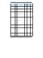
Table 3-1 Guide to the Selection of Peripheral Electrical Parts of MD280 Inverter
Recomme
Recomme
nded
nded
Recomme
Recommend
Input
Output
nded
ed Contactor
Side Main
Side Main
Control
(A)
Circuit
Circuit
Circuit
Wire (mm²)
Circuit
Breaker
Inverter Model
(MCCB)
(A)
Wire
Wire
(mm²)
(mm²)
MD280S0.4G
16
10
2.5
2.5
1.5
MD280S0.7G
16
10
2.5
2.5
1.5
MD280S1.5G
20
16
4
2.5
1.5
MD280S2.2G
32
20
6
4
1.5
MD280T0.7G
10
10
2.5
2.5
1.5
MD280T1.5G
16
10
2.5
2.5
1.5
MD280T2.2G
16
10
2.5
2.5
1.5
MD280T3.7G
25
16
4
4
1.5
MD280T3.7G/5.5P
32
25
4
4
1.5
MD280T5.5G/7.5P
40
32
4
4
1.5
MD280T7.5G/11P
63
40
4
4
1.5
MD280T11G/15P
63
40
6
6
1.5
MD280T15G/18.5P
100
63
6
6
1.5
MD280T18.5G/22P
100
63
10
10
1.5
MD280T22G/30P
125
100
16
10
1.5
MD280T30G/37P
160
100
16
16
1.5
MD280T37G/45P
200
125
25
25
1.5
MD280T45G/55P
200
125
35
25
1.5
MD280T55G/75P
250
160
50
35
1.5
MD280T75G/90P
250
160
70
35
1.5
MD280T90G/110P
350
350
120
120
1.5
- 46 -
MD280/MD280N User Manual
Mechanical and Electrical Installation
Recomme
Recomme
nded
nded
Recomme
Circuit
Recommend
Input
Output
nded
ed Contactor
Side Main
Side Main
Control
(A)
Circuit
Circuit
Circuit
Wire
Wire
Wire (mm²)
(mm²)
(mm²)
150
150
Breaker
Inverter Model
(MCCB)
(A)
MD280T110G/132P
400
400
1.5
MD280T132G/160P
500
400
185
185
1.5
MD280T160G/200P
600
600
150*2
150*2
1.5
MD280T200G/220P
600
600
150*2
150*2
1.5
MD280T220G/250P
800
600
185*2
185*2
1.5
MD280T250G/280P
800
800
185*2
185*2
1.5
MD280T280G/315P
800
800
150*3
150*3
1.5
MD280T315G/355P
800
800
150*4
150*4
1.5
MD280T355G/400P
1000
1000
150*4
150*4
1.5
MD280T400G/450P
1000
1000
150*4
150*4
1.5
3.2.2 Use instruction of peripheral electric parts:
Table 3-2 Guide to the Use Instruction of Peripheral Electric Parts of MD280 Inverter
Part
Installation
Function Description
Name
Location
Circuit
The front-end of
Disconnect the power supply in case of downstream equipment
breaker
the input circuit
is over current.
Between
Contactor
circuit
the
breaker
and the inverter
Power-on
and
power-off
of
the
inverter.Frequent
power-on/power-off operation on the inverter shall be avoided.
input side
AC input
Input side of the
reactor
inverter
1)
Improve the power factor of the input side.
2)
Eliminate the high order harmonics of the input side
effectively, and prevent other equipment from damaging
due to voltage waveform deformation.
3)
Eliminate the input current unbalance due to the
- 47 -
Mechanical and Electrical Installation
Part
MD280/MD280N User Manual
Installation
Function Description
Name
Location
unbalanced power phases.
1)
EMC
Input side of the
input filter
inverter
Reduce the external conduction and radiation interference
of the inverter;
2)
Reduce the conduction interference flowing from the
power
end
to
the
inverter,
thus
improving
the
anti-interference capacity of the inverter.
DC
reactor
MD280
series
inverter
of
above
7.5G/11P
adopts DC reactor
1)
Improve the power factor of the input side;
2)
Improve the overall efficiency and thermal stability
of the inverter.
3)
3) Effectively reduce the influence of high order harmonics
at the input side on the inverter and reduce the external
as standard
conduction and radiation interference.
The inverter output side generally has higher harmonic.When the
motor is far from the inverter, since there are many capacitors in
the circuit, certain harmonics will cause resonance in the circuit
Between
AC output
reactor
inverter
side
the
output
and
and bring in the following results:
1)
the
motor, close to the
Degrade the motor insulation performance and damage
the motor for the long run
2)
inverter
Generate large leakage current and cause frequent
inverter protection action
3)
In general, if the distance between the inverter and the
motor exceeds 100 meters, output AC reactor shall be
installed.
- 48 -
MD280/MD280N User Manual
Mechanical and Electrical Installation
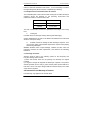
3.2.3 Wiring mode
Fig.3-4 Schematic Diagram for the Wiring Connection of Single-Phase Inverters of
MD280S0.4G/MD280S0.7G/MD280S1.5G/MD280S2.2G
- 49 -
Mechanical and Electrical Installation
MD280/MD280N User Manual
Fig.3-5 Schematic Diagram for the Wiring Connection of Three-Phase Inverters of
3MD280T0.7G to MD280T30G/37P
- 50 -
MD280/MD280N User Manual
Mechanical and Electrical Installation
Fig.3-6 Schematic Diagram for the Wiring Connection of Three-Phase Inverters of
MD280T37G/45P to MD280T55G/75P
- 51 -
Mechanical and Electrical Installation
MD280/MD280N User Manual
Fig.3-6 Schematic Diagram for the Wiring Connection of Three-Phase Inverters of
MD280T75G/90P to MD280T400G/450P
- 52 -
MD280/MD280N User Manual
Mechanical and Electrical Installation
3.2.4 Main Circuit Terminals and Wiring
Danger
z Make sure that the wiring operation shall be carried out only
when the power supply switch is in OFF position, or there may be risk
of electric shock.
z Only the professional technicians who have received training can
perform wiring, or it may cause injuries to the equipment and human
body.
z It shall be grounded reliably, or there may be risk of electric
shock or fire acciden.
注意
Caution
z
Make sure that the input power supply and the rated value
of the inverter shall be consistent, or it may damage the inverter.
z Make sure that the motor is compatible with the inverter, or the
motor may be damaged or inverter protection may be caused.
z Do not connect the power supply to the U, V, W terminals, or it
may damage the inverter.
z Do not connect the brake resistor to the DC bus terminals (+) and
(-) directly, or there may be fire accident.
1) Description of main circuit terminals of single-phase inverter:
Terminals
L1、L2
(+)、(-)
(+)、PB
Name
Single-phase power input
terminal
Negative and positive
terminals of DC bus
Connecting terminal of
braking resistor
U、V、W
Output terminal of inverter
Grounding terminal
Description
Connect to the AC single-phase 220V power supply
Shared DC bus input point
Connect to the braking resistor
Connect to the three-phase motor
Grounding terminal
2) Description of main circuit terminals of three-phase inverter:
Terminals
Name
Description
- 53 -
Mechanical and Electrical Installation
Terminals
R、S、T
(+)、(-)
MD280/MD280N User Manual
Name
Description
Three-phase power input
terminal
Negative
and
positive
P、(+)
Connecting terminal for
brake resistor
Connecting terminal for
external reactor
U、V、W
Output
terminal
Shared DC bus intput point (Connect to the external
brake unit above 37G/45P)
terminals of DC bus
(+)、PB
Connect to the AC three-phase 380V power supply
of
inverter
Grounding terminal
Connection points for the brake unit of of below 37G/45P
Connect to the external reactor
Connect to three-phase motor
Grounding terminal
1) Wiring Precautions
a) Input power supply terminals L1, L2, R, S or T:
There is no sequence requirement for the wiring at the Input side of the
inverter.
b) DC bus (+) and (-) terminals:
The DC bus (+) and (-) terminals still have residual voltage at the time of
power-off. Do not touch the equipment until the charge LED is OFF and the
voltage measured with multimeter is less than 36V.
When selecting external brake components for the inverter of above 45kW,
note that the connecting polarity must be correct, or the inverter may be
damaged and even fire accident may occur.
The wire length of the brake unit shall not be longer than 10 meters. Twisted
wires or pair wires shall be used and connected in parallel.
Do not connect the braking resistor directly to the DC bus, otherwise, the
inverter may be damaged, and fire may be caused.
c) Connecting terminals (+) and PB of brake resistor
The connecting terminals of the brake resistor are enabled only for the
inverter of below 37G/45P with built-in brake unit.
The recommended wiring distance for the brake resistor shall be less than
5m. Otherwise, the inverter may be damaged.
- 54 -
MD280/MD280N User Manual
Mechanical and Electrical Installation
d) Connecting terminals P and (+) of external reactor
When assembling the inverter of above 75G/90P with external reactor, it
needs to remove the connector between terminals of P and (+) and connect
the reactor between them instead.
e) Inverter output sides U, V and W:
The inverter output side cannot connect to the capacitor or surge absorber,
otherwise, the frequent inverter protection may be caus ed, or the inverter
may be damaged.
If the wire between the motor and the inverter is too long, electrical
resonance may be caused due to the influence of the distributed capacitance,
thus damaging the motor insulation or produce large leakage current to
trigger inverter over current protection. When the length of the motor cable is
longer than 100 meters, AC output reactor shall be installed.
f)
Grounding terminal
PE:
The terminal must be grounded reliably, and the resistance of the ground
wire must be less than 0.1Ω. Otherwise, fault may be caused, or the inverter
may be damaged.
Do not share the grounding terminal
power supply.
and terminal N of zero line of the
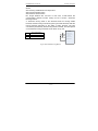
3.2.5 Control Terminals and Wiring
1)The terminals of the control circuit are arranged as shown in the following
diagram:
Fig.3-8 Terminal Layout of the Control Circuit
- 55 -
Mechanical and Electrical Installation
MD280/MD280N User Manual
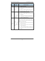
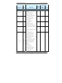
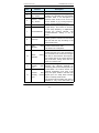
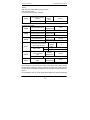
2)Function Description of Control Terminal
Table 3-3 Function Description of MD280 Inverter Control Terminal
Terminal
Type
Terminal
Function Description
Name
Provide +10V power supply for external units,
with maximum output current of 10mA.
External
+10V-GND
terminal of 10V
Power supply
power supply
It is generally used as the operating power
supply for the external potentiometer.
The potentiometer resistance range is 1kΩ to
5kΩ.
Provide +24V power supply for external units. It
+24V-COM
External
is generally used as the operating power supply
terminal of 24V
for digital input/output terminal and the external
power supply
sensor.
Maximum output current: 200mA
1. Input voltage range: DC 0V to 10V (can be
AI1-GND
Analog input
terminal 1
customized
as
non-standard
-10VDC
to
+10VDC)
2. Input impedance: 20kΩ
1. Input voltage range: DC 0V to 10V (can be
customized
Analog
as
non-standard
-10VDC
to
+10VDC)/0mA to 20mA, the selection of which
input
AI2-GND
Analog input
terminal 2
depends on jumper J1 on the control panel.
2. Input impedance: 20kΩ at the time of voltage
input; 500Ω at the time of current input.
3. Keyboard potentiometer input: It can switch
between
AI2
and
external
keyboard
potentiometer via Jumper J2.
Digital
Input
DI1-COM
1Digital Input 1
DI2-COM
Digital Input 2
DI3-COM
Digital Input 3
DI4-COM
Digital Input4
High-speed
DI5-COM
pulse input
terminal
1. Optical coupling isolation.
2. Input impedance: 3.3kΩ
In addition to the characteristics of DI1 to DI4, it
can also be used as the high-speed pulse input
channel.
Maximum input frequency: 50kHz.
- 56 -
MD280/MD280N User Manual
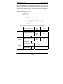
Mechanical and Electrical Installation
Terminal
Type
Terminal
Function Description
Name
The voltage or current output is determined by
Analog
output
AO-GND
Analog Output
1
jumper J3 on the control panel.
Output voltage range: 0V to 10V
Output current range: 0mA to 20mA.
Terminal
Type
Terminal
Function description
name
Optical coupling isolation,dual polarity open
DO1-COM
collector output
Digital output
Output voltage range: 0V to 24V
DO2-COM
Output current range: 0mA to 50mA
Digital
When it is used as high-speed pulse output,the
Output
maximum frequency can reach 50kHz;
FM-COM
High-speed
When it is used as open collector output, it is the
pulse output
same as DO1 in terms of specification.
Caution:The function of AO,FM,DO3 share the
channel,only one of which can be selected.
Relay
output
T/A-T/B
T/A-T/C
Normally
closed terminal
Normally open
terminal
Contact driving capacity:
AC250V,3A,COSφ=0.4。
DC 30V,1A
485
A+/AAuxiliary
communication
Standard 485 interface
port
interface
External
Keypad
keyboard
interface
Standard RJ45 network cable interface, used to
provide signals for the external keyboard.
3) Description of wiring of control terminals:
A. Analog input terminal:
Because the weak analog signal will be easily affected by the
external interference, generally shielded cable shall be used, and the cable
length shall be as short as possible and no longer than 20 meters, as
shown in Fig.3-9, In case the analog signal is subject to severe interference,
- 57 -
Mechanical and Electrical Installation
MD280/MD280N User Manual
and analog signal source side shall be installed with filter capacitor or
ferrite magnetic core, as shown in Fig.3-10.
Less than 20 Meters
Potentiometer
Fig.3-7 Schematic diagram for Wiring of Analog Input Terminal
- 58 -
MD280/MD280N User Manual
Mechanical and Electrical Installation
Cross in the Same
Direction or Wind
2 to 3 Coils in the
Same Direction
External
Analog Source
Ferrite Magnetic
Ring
Fig.3-8 Schematic Diagram for Wiring of Analog Input Terminal
B. Digital input terminal:
It needs to employ shielded cable generally, with wiring distance of no
longer than 20 meters.
When valid driving is adopted, necessary filtering measures shall be
taken to prevent the interference to the power supply.
It is recommended to use the contact control mode.
B. Digital output terminal:
When connecting to the load, the digital output terminal is directly
connected between D0 and 24V, and there already exists continuous-flow
absorption circuit inside the inverter. The load current is less than 50mA.If
the load is too high, please transit via the replay.
- 59 -
Mechanical and Electrical Installation
MD280/MD280N User Manual
- 60 -
MD280/MD280N User Manual
Mechanical and Electrical Installation
Operation and Display
61
Operation and Display
MD280/MD280N User Manual
Chapter 4 Operation and Display
4.1 Introduction to Operation and Display Interface
Modification of function parameter, monitoring of inverter operation, control of
inverter operation (start and stop) can be performed through the operation
panel.
Fig.4-1 Schematic Diagram for the External Operation Panel of Inverter without
Potentiometer
Fig.4-2 Schematic Diagram for the External Keyboard of Inverter with
Potentiometer
1) Function LED Indictor Description:
RUN: When it is OFF, it indicates that the inverter is in stop status. When it is
ON, it indicates that the inverter is in running status.
LOCAL/REMOT: The LED indicator for keypad operation, terminal operation
and remote operation; when it is OFF, it is under keypad operation control;
when it is ON, it is under terminal operation control; when it flashes, it is
under communication operation control.
2) Unit LED indictor description:
Hz refers to unit of frequency
A refers to unit of current
V refers to unit of voltage
- 62 -
MD280/MD280N User Manual
Operation and Display 示
RMP (Hz + A) refers to unit of rotation velocity
% (A + V) refers to percentage
3)Data display region
Five-digit LED display, able to display setup frequency, output frequency,
various monitor data and alarm code.
4)Keyboard button description:
Table 4-1 Keyboard Function Table
Button
PRG
ENTER
Name
Programming
Function
Enter or exit from first-level menu.
key
Confirmation
Increase of the data or function code.
key
∧
Increase key
Increase of the data or function code
∨
Decrease key
Decrease of the data or function code
On the stop display interface or running display interface, it
》
Shift key
can be used to circularly select the display parameters. When
modifying the parameters, it can be used to select the bits of
parameter for modification.
RUN
Running key
It is used to start the running of the inverter under keyboard
control mode.
In running status, it can stop the running by pressing this key.
STOP/RES
Stop/reset
In alarm status, it can reset operation with this key. The
characteristics of this key are limited by function code F7-17.
MF.K
Multi-function
selection key
It is used as function switching selection according to F-15.
4.2 Description of Function Code Viewing and Modification
Method
The operation panel of MD280 inverter adopts three-level menu structure to
perform parameter setting.
The three-level menu includes: function parameter group (level 1 menu) →
function code (level 2 menu) → setting value of function code (level 3
menu).The operation process is as shown in Fig.4-3
- 63 -
Operation and Display
MD280/MD280N User Manual
Parameter Set
Modification
Modification of
Function Code Numeric Values of
Function Code
Modification
First-level Menu Second-level
Menu
Third-level Menu
Fig.4-3 Operation Process of Three-Level Menu
Caution: When operating on level 3 menu, press PRG key or ENTER key to
return to level-2 menu. The difference between ENTER and PRG keys is that
pressing ENTER KEY will save the setup parameter and return to level 2
menu and then automatically shift to the next function code, while pressing
PRG key will directly return to level 2 menu without saving the parameter,
and it will return to the current function code.
Take the modification of function code F0-05 from 10.00Hz to 15.00Hz as an
example. (The boldface bit indicates the flashing bit)
Fig.4-4 Example of Parameter Editing Operation
In level 3 menu, if the parameter has no flashing bit, it indicates that the
function code cannot be modified. The possible reasons include:
1) The function code is an unchangeable parameter, such as Such as actual
detection parameter, running record parameter, etc.
2) The function code cannot be modified in running status but can be
modified after the unit is stopped.
4.3 Viewing Method of Status Parameter
When the inverter is in stop or running status, multiple status parameters can
be displayed. It can select whether this parameter is to be displayed in binary
bit with the function codes F7-13 (running parameter) and F7-14 (stop
parameter). Refer to the descriptions of F7-13 and F7-14 in Chapter 6 for the
meanings of each bit.
In stop status, a total of 8 stop status parameters can be selected to display
or not to display, including setup frequency, bus voltage, DI input status, DO
output status, analog input AI 1 voltage, analog input AI2 voltage, actual
counting value, actual length value, the display of which can be switched by
pressing “》”key.
- 64 -
MD280/MD280N User Manual
Operation and Display 示
In running status, there are a total of 16 running status parameters, including
setup frequency, output voltage, output current, output power, DI input status,
DO output status, analog input AI1 voltage, analog input AI2 voltage, actual
counting value, actual length value, PID setup, PID feedback, pulse input
frequency, the display of which can be switched by pressing “》”key.
4.4 Password Setting
The inverter provides user password protection function. When FP-00 is set
to non- zero value, it is user password and enabled after exiting the function
code editing status. When the user presses the PRG key again, “-----“will be
displayed to require the user to enter user password, or the user cannot enter
the general menu.
To cancel the password protection function, the user needs to enter the
relevant interface through password, and change the FP-00 setting to 0.
- 65 -
Operation and Display
MD280/MD280N User Manual
- 66 -
MD280/MD280N User Manual
Function Parameter Table
Function Parameter Table
- 67 -
Function Parameter Table
MD280/MD280N User Manual
Chapter 5 Function Parameter Table
When FP-00 is set to non-zero value, it means that the parameter
protection password is set and only when correct password is input can the
user enter the parameter menu. To cancel the password, it needs to set
FP-00 to 0.
The parameters in the shortcut menu are out of password protection.
The symbols in the function table are explained as follows:
“☆” indicates that the parameter setup value can be modified when the
inverter is in stop status and running status;
“★” indicates that the parameter setup value cannot be modified when the
inverter is in the running status;
“●” indicates that the parameter value is the actual detection record and
cannot be modified.
“*” indicates that the parameter is “Factory default parameter” and can be
set only by the manufacturer, and the user is forbidden to perform any
operation.
- 68 -
MD280/MD280N User Manual
Function Parameter Table
Factory
Minimu
Function code
Name
Setup Range
Default
Change
m Unit
Value
Group F0 Basic function group
0: Operation panel control channel
F0-00
Comma
(LED ON)
nd
1: Terminal command channel
source
selection
1
0
☆
1
0
★
1
0
☆
0.01Hz
50.00Hz
☆
0.01Hz
50.00Hz
★
(LED OFF)
2.
Serial
port
communication
control channel (LED FLASHING)
0: Digital setting (UP and Down
adjustment)
1: AI1
2: AI2
Frequen
F0-01
cy
source
selection
3: PULSE setting (DI5)
4: MS speed
5:PLC
6:PID
7:AI1+AI2
8:Communication setup
9:PID + AI1
10:PID + AI2
Digital
setup
F0-02
0:Without memory
frequenc 1:Power fault memory
y
memory
2:Stop memory
3:Stop and power fault memories
selection
Pre-set
F0-03
frequenc
y
F0-04
Maximu
m
0.00Hz to maximum frequency
(F0-04)
50.00Hz to 630.00Hz
- 69 -
Function Parameter Table
MD280/MD280N User Manual
Factory
Minimu
Function code
Name
Setup Range
Default
Change
m Unit
Value
frequenc
y
Frequen
cy
F0-05
source
upper
limit
0:Numerical value setting (F0-06)
1:AI1
1
0
★
0.01Hz
50.00Hz
☆
0.01Hz
0.00Hz
☆
1
0
★
2:AI2
3:PULSE setting (DI5)
Frequen
F0-06
cy upper 0.00Hz to maximum frequency
limit
(F0-04)
setup
Frequen
F0-07
cy upper 0.00Hz to frequency upper limit
limit
(F0-06)
setup
Speed-u
F0-08
p/speed- 0: s (second)
down
1: m (minute)
time unit
F0-09
Speed-u
0.00s(m) to 300.00s(m)
0.01s(m)
own time 0.00s(m) to 300.00s(m)
0.01s(m)
p time 1
Speed-d
F0-10
1
Carrier
F0-11
frequenc 0.5kHz to 16.0kHz
0.1kHz
y
F0-12
F0-13
Running
0: Consistent direction
direction 1: Reverse direction
Referen
0: Maximum frequency
- 70 -
Model
dependent
Model
dependent
Model
dependent
☆
☆
☆
1
0
☆
1
0
★
MD280/MD280N User Manual
Function Parameter Table
Factory
Minimu
Function code
Name
Setup Range
Default
Change
m Unit
Value
ce
1: Setup value
frequenc
y of
speed-u
p/speeddown
time
Running
frequenc
y
F0-14
UP/DO
WN
0: Running frequency
1:Setup frequency
1
0
☆
1
0
★
1
0
☆
1%
100%
☆
referenc
e
0:Digital setup(UP or DOWN can
be modofied)
Auxiliary
Frequen
F0-15
cy
source Y
selection
1:AI1
2:AI2
3:PULSE setting(DI5)
4:MS speed
5:PLC
6:PID
7:AI1+AI2
8:Communication setup
Auxiliary
frequenc
y source
F0-16
Y
selection
at the
0:Relative to maximum frequency
1:Relative to
frequency source
X
time of
overlap
F0-17
Auxiliary
0% to 150%
- 71 -
Function Parameter Table
MD280/MD280N User Manual
Factory
Minimu
Function code
Name
Setup Range
Default
Change
m Unit
Value
frequenc
y source
Y
selection
at
the
time
of
overlap
Frequen
F0-18
cy
source Y
selection
0:Main
1:Main + auxiliary
2:MainÅ>Auxiliary
1
0
☆
0.01Hz
0.00Hz
☆
3:MainÅ> Main + auxiliary
4:AuxiliaryÅ>Main + auxiliary
Auxiliary
frequenc
F0-20
y source 0.00Hz to Maximum frequency
digital
F0-04
setup
offset
Group F1
Motor Parameters and V/F Control Parameters
Motor
F1-00
rated
0.2kW to 1000.0kW
0.1kw
power
Motor
F1-01
rated
0V to 480V
1V
voltage
Motor
F1-02
rated
0.1A to 6553.5A
0.1A
current
Model
dependent
Model
dependent
Model
dependent
★
★
★
Motor
F1-03
rated
0.01Hz
to
maximu
frequenc (F0-04)
y
- 72 -
frequency
0.01Hz
Model
dependent
★
MD280/MD280N User Manual
Function Parameter Table
Factory
Minimu
Function code
Name
Setup Range
Default
Change
m Unit
Value
V/F
F1-04
F1-05
0: Linear V/F curve
curve
1:Multiple-point V/Fcurve
setup
2:Square V/F curve
Torque
hoist
0.0%(auto)
0.1% to 30.0%
1
0.1%
0
Model
dependent
★
☆
Torque
boost
F1-06
cutoff
frequenc
0.00Hz
to
maximu
frequency
(F0-04)
0.01Hz
50.00Hz
★
0.01Hz
0.00Hz
★
0.1%
0.0%
★
0.01Hz
0.00Hz
★
0.1%
0.0%
★
0.01Hz
0.00Hz
★
y
Multi-poi
nt V/F
F1-07
frequenc 0.00Hz to F1-09
y point
f1
Multi-poi
nt V/F
F1-08
frequenc 0.0% to 100.0%
y point
v1
Multi-poi
nt V/F
F1-09
frequenc F1-07 to F1-11
y point
f2
Multi-poi
F1-10
nt V/F
voltage
0.0% to 100.0%
point v2
F1-11
Multi-poi F1-09 to Motor rated frequency
nt V/F
(F1-03)
- 73 -
Function Parameter Table
MD280/MD280N User Manual
Factory
Minimu
Function code
Name
Setup Range
Default
Change
m Unit
Value
frequenc
y point
f3
Multi-poi
F1-12
nt V/F
voltage
0.0% to 100.0%
0.1%
0.0%
★
0.0% to 200.0%
0.1%
0.0%
☆
1
64
☆
point v3
Slip
compen
F1-13
sation
coefficie
nt
Over
F1-14
excitatio
0 to 200
n gain
F1-15
No-load
0.1A to
current
(F1-02)
motor rated current
0.1A
Stator
F1-16
resistan
0.001Ω to 65.535Ω
0.001Ω
ce
Oscillati
F1-17
Model
dependent
Model
dependent
☆
☆
0 to 100
on
1
suppres
Model
dependent
☆
sion gain
F1-18
Tuning 0:No operation
selection 1:Tuning
1
0
★
1
1
☆
Oscillati
on
F1-19
suppres
0 to 3
sion
mode
- 74 -
MD280/MD280N User Manual
Function Parameter Table
Factory
Minimu
Function code
Name
Setup Range
Default
Change
m Unit
Value
Group F2 Input terminal
DI1
F2-00
terminal
function
selection
0: None
1: Run forward (FWD)
1
1
★
1
2
★
1
4
★
1
8
★
1
0
★
2:RUN reverse (REV)
3: Three-line running control
DI2
F2-01
terminal
function
selection
4: Forward jog (FJOG)
5: Reverse jog (RJOG)
6. Terminal UP
7. Terminal DOWN
DI3
F2-02
terminal
function
8: Free stop
9: Fault reset (RESET)
selection 10.Pause during the operation
11: External fault input normally
DI4
F2-03
terminal
function
open
12: External fault input normally
selection closed
13. MS speed terminal 1
14. MS speed terminal 2
15. MS speed terminal 3
16:Speed-up/speed-down
time
selection terminal
DI5
F2-04
terminal
function
17: UP/DOWN setup clearing
18:Stop DC brake terminal
19:Speed-up/speed-down
selection disabled
20. PID pause
21: PLC status reset
22:Swing frequency pause
23: Counter input (DI5)
24: Counter reset
- 75 -
Function Parameter Table
MD280/MD280N User Manual
Factory
Minimu
Function code
Name
Setup Range
Default
Change
m Unit
Value
25:Length counting input (DI5)
26:Length counting reset
27:Interchange of AI1 and AI2
settings
28: Switch the frequency source to
AI1 , it is enabled only set
F0-18(frequency
+
selection)to
0.
29:DC brake at stop enabled
30:Keyboard
command
source
command
source
switching
31:Terminal
switching
32:Switch between the first motor
and the second motor
DI
F2-05
filtering
1 to 10
1
4
☆
1
0
★
0.01Hz/s
1.00Hz/s
☆
0.00V to F2-10
0.01V
0.02V
☆
-100.0% to 100.0%
0.1%
0.0%
☆
time
Terminal
F2-06
comman
d mode
0: two-line mode 1
1: two-line mode 2
2: three-line mode1
3: three-line mode2
Terminal
F2-07
UP/DO
WN
0.01Hz/s to 100.00Hz/s
velocity
AI1
F2-08
minimu
m input
F2-09
Corresp
- 76 -
MD280/MD280N User Manual
Function Parameter Table
Factory
Minimu
Function code
Name
Setup Range
Default
Change
m Unit
Value
onding
Setup of
AI
minimu
m input
A1
F2-10
maximu
F2-08 to 10.00V
0.01V
10.00V
☆
1
0
★
-100.0% to 100.0%
0.1%
100.0%
☆
0.00s to 10.00s
0.01s
0.10s
☆
0.00V to F2-16
0.01V
0.02V
☆
-100.0% to 100.0%
0.1%
0.0%
☆
m input
A1
maximu
F2-11
m input
0: F2-12
correspo 1: Set by AI2
nding
setup
A1
maximu
F2-12
m input
correspo
nding
setup
AI1 input
F2-13
filtering
time
F2-14
Minimu
m input
AI2
minimu
F2-15
m input
correspo
nding
setup
- 77 -
Function Parameter Table
MD280/MD280N User Manual
Factory
Minimu
Function code
Name
Setup Range
Default
Change
m Unit
Value
AI2
F2-16
maximu
F2-14 to 10.00V
0.01V
10.00V
☆
1
0
★
-100.0% to 100.0%
0.1%
100.0%
☆
0.00s to 10.00s
0.01s
0.10s
☆
0.01kHz
0.00kHz
☆
0.1%
0.0%
☆
m input
AI2
maximu
m input
F2-17
correspo
nding
0: F2-18
1: Set by AI1
setup
mode
AI2
maximu
F2-18
m input
correspo
nding
setup
AI2 input
F2-19
filtering
time
PULSE
input
F2-20
minimu
m
0.00kHz to F2-22
frequenc
y
PULSE
input
minimu
F2-21
m
-100.0% to 100.0%
frequenc
y
correspo
- 78 -
MD280/MD280N User Manual
Function Parameter Table
Factory
Minimu
Function code
Name
Setup Range
Default
Change
m Unit
Value
nding
setup
PULSE
input
F2-22
maximu
m
F2-20 to 50.00kHz
0.01kHz
50.00kHz
☆
1
0
★
0.1%
100.0%
☆
0.01s
0.10s
☆
1
0
☆
frequenc
y
PULSE
input
maximu
m
F2-23
0: F2-24
frequenc 1: Set by AI1
y
2: Set by AI2
correspo
nding
setup
PULSE
input
maximu
m
F2-24
frequenc -100.0% to 100.0%
y
correspo
nding
setup
PULSE
F2-25
input
filtering
0.00s to 10.00s
time
F2-26
DI input
terminal
0 to 31
- 79 -
Function Parameter Table
MD280/MD280N User Manual
Factory
Minimu
Function code
Name
Setup Range
Default
Change
m Unit
Value
valid
status
selection
AI1 as
F2-27
function
selection
同F2-00
1
0
★
同F2-00
1
0
★
1
2
☆
1
2
☆
1
1
☆
1
4
☆
1
0
☆
of DI6
AI2 as
the
F2-28
function
selection
of DI7
Group F3 Output terminal
Multifun
ctional
F3-00
terminal
output
0: FM (FMP pulse output)
1:FM (DO3 digital output)
2: AO (Analog output)
selection
RELAY
F3-01
output
selection
0: No output
1: Inverter being running
2: Fault output
DO1
F3-02
output
selection
DO2
F3-03
output
selection
FM
F3-04
(DO3)
output
selection
3:Frequency level detection FDT
arrival
4:Frequency arrival
5:Frequency upper limit arrival
6: Frequency lower limit arrival
7:In zero speed operation
8: Motor overload alarm
9: Inverter overload alarm
10: Setup counting value arrival
- 80 -
MD280/MD280N User Manual
Function Parameter Table
Factory
Minimu
Function code
Name
Setup Range
Default
Change
m Unit
Value
11: Designated counting arrival
12:Length arrival
13: PLC circulation end
14: Run time arrival
15: Communication control
16: RUN ready
17: AI1>AI2
18:Zero-current is
detected
0: Running frequency
1: Setup frequency
2: Output current
F3-05
FMP
3: Output power
and AO
4: PULSE input
output
selection
1
0
☆
-100.0% to 100.0%
0.1s
0.0%
☆
-10.00 to 10.00
0.01
1.00
☆
0.1kHz
50.0kHz
☆
0.1s
0.0s
☆
5: AI1
6: AI2
7:Length value
8:Counting value
9:Communication control output
AO zero
F3-06
offset
coefficie
nt
F3-07
AO gain
Maximu
m
F3-08
frequenc 0.1kHz to 50.0kHz
y of FMP
output
F3-09
RELAY
output
0.0s to 3600.0s
- 81 -
Function Parameter Table
MD280/MD280N User Manual
Factory
Minimu
Function code
Name
Setup Range
Default
Change
m Unit
Value
delay
time
DO1
F3-10
output
delay
0.0s to 3600.0s
0.1s
0.0s
☆
0.0s to 3600.0s
0.1s
0.0s
☆
0.0s to 3600.0s
0.1s
0.0s
☆
1
0
☆
1
0
★
1
0
☆
1
20
☆
time
DO2
F3-11
output
delay
time
DO3
F3-12
output
delay
time
DO
output
F3-13
terminal
valid
0 to 15
status
selection
Group F4 Start/Stop Control
F4-00
Startup
mode
Rotation
F4-01
speed
tracking
mode
0: Direct startup
1:Rotation velocity tracking startup
0:Start from stop frequency
1: Start from zero speed
2: Start from maximum frequency
Rotation
F4-02
speed
tracking
1 to 100
fastness
- 82 -
MD280/MD280N User Manual
Function Parameter Table
Factory
Minimu
Function code
Name
Setup Range
Default
Change
m Unit
Value
and
slownes
s
Startup
F4-03
frequenc
y
0.00Hz to maximum frequency
0.01Hz
0.00Hz
★
0.0s to 36.0s
0.1s
0.0s
★
0% to 100%
1%
0%
★
0.0s to 36.0s
0.1s
0.0s
★
1
0
★
0.0% to 100.0%
0.1%
20.0%
★
0.0% to 100.0%
0.1%
20.0%
★
(F0-04)
Startup
frequenc
F4-04
y
retention
time
DC
brake
F4-05
current
at
startup
DC
F4-06
brake
time at
startup
0 : Straight line speed-up and
Speed-u speed-down
F4-07
p/speed/ 1: S curve speed-up/ speed-down
down
A
mode
2:S curve speed-up/ speed-down
B
Start
F4-08
segment
time of S
curve
F4-09
End
- 83 -
Function Parameter Table
MD280/MD280N User Manual
Factory
Minimu
Function code
Name
Setup Range
Default
Change
m Unit
Value
segment
time of S
curve
F4-10
Stop
0: Speed-down to stop
mode
1: Free stop
1
0
☆
0.01Hz
0.00Hz
☆
0.0s to 36.0s
0.1s
0.0s
☆
0% to 100%
1%
0%
☆
0.0s to 36.0s
0.1s
0.0s
☆
0% to 100%
1%
100%
☆
0.01Hz
2.00Hz
☆
DC
brake at
F4-11
stop
Startup
0.00Hz to maximum frequency
(F0-04)
frequenc
y
DC
brake at
F4-12
stop
waiting
time
DC
F4-13
brake
current
at stop
DC
F4-14
brake
current
at stop
Brake
F4-15
utilizatio
n ratio
Group F5 Auxiliary Function
F5-00
Jog
running
0.00Hz to maximum frequency
(F0-04)
- 84 -
MD280/MD280N User Manual
Function Parameter Table
Factory
Minimu
Function code
Name
Setup Range
Default
Change
m Unit
Value
frequenc
y
Jog
F5-01
speed-u
0.00s to 300.00s
0.01s
20.00s
☆
0.00s to 300.00s
0.01s
20.00s
☆
1
0
☆
p time
Jog
F5-02
speed-d
own time
Jog
enabled
F5-03
during
operatio
0: Disabled
1: Enable
n
F5-04
Speed-u
p time 2
0.00s(m) to 300.00s(m)
Speed-d
F5-05
own time 0.00s(m) to
300.00s(m)
2
Skip
F5-06
frequenc
y
0.00Hz to maximum frequency
(F0-04)
0.01s(m
Model
)
dependent
☆
0.01s(m
Model
)
dependent
0.01Hz
0.00Hz
☆
0.01Hz
0.00Hz
☆
0.1s
0.0s
☆
☆
Skip
frequenc
F5-07
y
amplitud
0.00Hz to maximum frequency
(F0-04)
e
Dead
zone
F5-08
time of
0.0s to 100.0s
Forward
and
- 85 -
Function Parameter Table
MD280/MD280N User Manual
Factory
Minimu
Function code
Name
Setup Range
Default
Change
m Unit
Value
reverse
rotations
Reverse
F5-09
rotation
control
0:Reverse rotation enabled
1:Reverse rotation disabled
1
0
☆
1
0
☆
0.1s
0.0s
☆
1h
0h
☆
1
0
☆
1
0
☆
Run with
frequenc
F5-10
y below
0: Run with frequency lower limit
frequenc 1: Delay to stop
y lower
limit
Delay
duration
of stop
with
F5-11
frequenc 0.0s to 3600.0s
y below
frequenc
y lower
limit
Setup
F5-12
running
0h to 65535h
time
Action
selection
F5-13
at the
0: Continue to run
arrival of 1: Stop
running
time
Startup
F5-14
protectio
n
0: Disabled
1: Enabled
- 86 -
MD280/MD280N User Manual
Function Parameter Table
Factory
Minimu
Function code
Name
Setup Range
Default
Change
m Unit
Value
selection
Frequen
cy
F5-15
detectio
n value
0.00Hz to maximum frequency
0.01Hz
50.00Hz
☆
0.0% to 100.0%
0.1%
5.0%
☆
0.0% to 100.0%
0.1%
0.0%
☆
1
0
☆
1
0
★
1
1
★
(F0-04)
(FDT
level)
Frequen
cy
F5-16
detectio
n
hysteres
is value
Frequen
cy arrival
F5-17
detectio
n
amplitud
e
Random
F5-18
PWM
0 to 10
gain
Modulati
F5-19
on mode
selection
0:Asynchronous modulation
1:Synchronous modulation
Quick
current
F5-20
limit
function
0: Disabled
1: Enabled
selection
- 87 -
Function Parameter Table
MD280/MD280N User Manual
Factory
Minimu
Function code
Name
Setup Range
Default
Change
m Unit
Value
F5-21
Wake-u
p
Wake-up frequency to maximum
0.01Hz
0.00Hz
☆
0.1s
0.0s
☆
0.01Hz
0.00Hz
☆
0.1s
0.0s
☆
0.1%
200.0%
☆
0.01s
0.00s
☆
1
0
★
1
0
☆
frequency(F0-04)
frequenc
y
F5-22
Wake-u
p
0.0s to 6500.0s
delay
time
Sleep
F5-23
0.00Hz to maximum frequency
frequenc (F0-04)
y
Sleep
F5-24
0.0s to 6500.0s
delay
time
F5-25
Software 0.0% to 300.0% ( motor rated
over-cur
current)
rent
points
F5-26
Software 0.00s(not detection)
over-cur
0.01s to 600.00s
rent
detectio
n delay
time
F5-37
Dead-zo 0 to 1
ne
compen
sation
mode
selection
F5-38
Cooling
fan
0:Cooling fan startup of motor
running
- 88 -
MD280/MD280N User Manual
Function Parameter Table
Factory
Minimu
Function code
Name
Setup Range
Default
Change
m Unit
Value
control
1:
Cooling
fan
running
after
power-on
Group F6 PID Function
0:F6-01
F6-00
PID
1: AI1
referenc
2: AI2
e source
1
0
☆
0.0% to 100.0%
0.1%
50.0%
☆
0.0s to 3000.0s
0.1s
0.0s
☆
1
0
☆
1
0
☆
0 to 65535
1
1000
☆
0.1 to 100.0
0.1
20.0
☆
3: PULSE (DI5)
4: MS speed
PID
F6-01
numeric
al value
setup
PID
referenc
F6-02
e
change
duration
0:AI1
PID
F6-03
feedbac
k source
1:AI2
2:PULSE (DI5)
3:AI1-AI2
PID
F6-04
action
direction
0: Positive
1: Negative
PID
referenc
F6-05
e
feedbac
k range
F6-06
Proporti
- 89 -
Function Parameter Table
MD280/MD280N User Manual
Factory
Minimu
Function code
Name
Setup Range
Default
Change
m Unit
Value
onal
gain P
F6-07
Integral
time I
0.01s to 10.00s
0.01s
2.00s
☆
0.000s to 10.000s
0.001s
0.000s
☆
0.1%
0.0%
☆
1
0
☆
1
0
☆
0.00% to 100.0%
0.1%
0.0%
☆
0.0% to 50.0%
0.1%
0.0%
☆
0.01s to 300.00s
0.01s
10.00s
☆
0.1% to100.0%
0.1%
50.0%
☆
Different
F6-08
ial time
D
F6-09
Deviatio
n limit
PID
F6-10
operatio
n mode
0.0% to 100.0%
0:Stop without operation
1: Operation upon stop
Group F7 Swing Frequency, Fixed Length and Counting
Swing
F7-00
frequency
setup
mode
0: Relative to the center frequency
1:
Relative
to
the
maximum
frequency
Swing
F7-01
frequency
amplitude
Kick
F7-02
frequency
amplitude
Swing
F7-03
frequency
cycle
Triangle
F7-04
wave
boost
time
- 90 -
MD280/MD280N User Manual
Function Parameter Table
Factory
Minimu
Function code
Name
Setup Range
Default
Change
m Unit
Value
coefficient
F7-05
F7-06
Setup
length
Actual
length
0m to 65535m
1m
1000m
☆
0m to 65535m
1m
0m
☆
0.1
100.0
☆
1 to 65535
1
1000
☆
1 to 65535
1
1000
☆
0.0001
1.0000
☆
1
1
☆
1h
-
●
1
799
☆
Pulse
F7-07
numberper 0.1 to 6553.5
meter
Setup
F7-08
counting
value
Designate
F7-09
d counting
value
Load
F7-10
speed
display
0.0001 to 6.5000
coefficient
Decimal
F7-11
point
position
0: No decimal place
1: One decimal place
2: Two decimal places
3: Three decimal places
Accumulat
F7-12
ed running 0h to 65535h
time
LED
F7-13
running
display
1 to 65535
parameter
- 91 -
Function Parameter Table
MD280/MD280N User Manual
Factory
Minimu
Function code
Name
Setup Range
Default
Change
m Unit
Value
LED stop
F7-14
display
1 to 511
1
51
☆
1
0
★
1
0
☆
-
-
●
1
0
★
parameter
0: MF.K invalid
1:
Switching
operation
MF.K key
F7-15
function
selection
between
panel
the
command
channel and the remote command
channel
(terminal
command
channel or serial port command
channel)
2: Switching between forward and
reverse rotation
3: Forward jog
0:
STOP/RE
F7-16
S key
function
The
stop
function
of
STOP/RES key is valid only in the
keyboard control mode.
1: The stop function of STOP/RES
key is valid in any control mode.
Software
F7-17
version
0.01 to 655.35
No.
Group F8 MS speed and PLC
0: F8-01 reference
1:
MS
F8-00
speed 0
referenc
e mode
AI1
2: AI2
3: pulse
4: PID
5:preset frequency ( F0-03 )
reference,
UP/DOWN
changed
- 92 -
can
be
MD280/MD280N User Manual
Function Parameter Table
Factory
Minimu
Function code
Name
Setup Range
Default
Change
m Unit
Value
F8-01
F8-02
F8-03
F8-04
F8-05
F8-06
F8-07
F8-08
MS
speed 0
MS
speed 1
MS
speed 2
MS
speed 3
MS
speed 4
MS
speed 5
MS
speed 6
MS
speed 7
PLC
F8-09
running
mode
-100.0% to 100.0% (frequency
upper limit F0-05)
-100.0% to 100.0% (frequency
upper limit F0-05)
-100.0% to 100.0% (frequency
upper limit F0-05)
-100.0% to 100.0% (frequency
upper limit F0-05)
-100.0%
to
100.0%(frequency
upper limit F0-05)
100.0% to 100.0% (frequency
upper limit F0-05)
-100.0% to 100.0% (frequency
upper limit F0-05)
-100.0% to 100.0% (frequency
upper limit F0-05)
0.1%
0.0%
☆
0.1%
0.0%
☆
0.1%
0.0%
☆
0.1%
0.0%
☆
0.1%
0.0%
☆
0.1%
0.0%
☆
0.1%
0.0%
☆
0.1%
0.0%
☆
1
0
☆
1
0
☆
1
0
☆
0.1s(h)
0.0s(h)
☆
0: Single running stop
1:Single running counting remains
the final value
2: Continuous circulation
PLC
power
F8-10
fault
memory
0:Power fault without memory
1: Power fault memory
selection
F8-11
F8-12
Running
0: s (second)
time unit 1: h (hour)
0-segme 0.0s(h) to 6553.5s(h)
- 93 -
Function Parameter Table
MD280/MD280N User Manual
Factory
Minimu
Function code
Name
Setup Range
Default
Change
m Unit
Value
nt
running
time of
PLC
Speed-u
p/speeddown
time
F8-13
selection
of
0:Speed-up/speed-down time 1
1:Speed-up/speed-down time 2
1
0
☆
0.1s(h)
0.0s(h)
☆
1
0
☆
0.1 s(h)
0.0s(h)
☆
0-segme
nt of
PLC
Running
time of
F8-14
the first
0.0s(h) to 6553.5s(h)
segment
of PLC
Speed-u
p/speeddown
time
F8-15
selection
of
the
0:Speed-up/speed-down time 1
1:Speed-up/speed-down time 2
first
segment
of PLC
Running
time of
F8-16
the
second
0.0s(h) to 6553.5s(h)
segment
of PLC
- 94 -
MD280/MD280N User Manual
Function Parameter Table
Factory
Minimu
Function code
Name
Setup Range
Default
Change
m Unit
Value
Speed-u
p/speeddown
time
F8-17
selection
of
the
0:Speed-up/speed-down time 1
1:Speed-up/speed-down time 2
1
0
☆
0.1s(h)
0.0s(h)
☆
1
0
☆
0.1s(h)
0.0s(h)
☆
1
0
☆
second
segment
of PLC
Running
time of
F8-18
the third
0.0s(h) to 6553.5s(h)
segment
of PLC
Speed-u
p/speeddown
time
F8-19
selection
of
the
0: Speed-up/speed-down time 1
1: Speed-up/speed-down time 2
third
segment
of PLC
Running
time of
F8-20
the
fourth
0.0s(h) to 6553.5s(h)
segment
of PLC
Speed-u
F8-21
p/speed- 0: Speed-up/speed-down time 1
down
1: Speed-up/speed-down time 2
time
- 95 -
Function Parameter Table
MD280/MD280N User Manual
Factory
Minimu
Function code
Name
Setup Range
Default
Change
m Unit
Value
selection
of
the
fourth
segment
of PLC
Running
time of
F8-22
the fifrth
0.0s(h) to 6553.5s(h)
0.1s(h)
0.0s(h)
☆
1
0
☆
0.1s(h)
0.0s(h)
☆
1
0
☆
segment
of PLC
Speed-u
p/speeddown
time
F8-23
selection
of
the
0:Speed-up/speed-down time 1
1:Speed-up/speed-down time 2
fifth
segment
of PLC
Running
time of
F8-24
the sixth
0.0s(h) to 6553.5s(h)
segment
of PLC
Speed-u
p/speeddown
time
F8-25
selection
of
the
0:Speed-up/speed-down time 1
1:Speed-up/speed-down time 2
sixth
segment
of PLC
- 96 -
MD280/MD280N User Manual
Function Parameter Table
Factory
Minimu
Function code
Name
Setup Range
Default
Change
m Unit
Value
Running
time of
F8-26
the
seventh
0.0s(h) to 6553.5s(h)
0.1s(h)
0.0s(h)
☆
1
0
☆
1
5
☆
1
0
☆
segment
of PLC
Speed-u
p/speeddown
time
F8-27
selection
of
the
0: Speed-up/speed-down time 1
1: Speed-up/speed-down time 2
seventh
segment
of PLC
Group F9 Reserved
F9-00
Reserved
Group FA Communication Parameters
0:300BPS
1:600BPS
2:1200BPS
FA-00
Baud
3:2400BPS
rate
4:4800BPS
5:9600BPS
6:19200BPS
7:38400BPS
FA-01
Data
format
0: No parity check
1: Even check
2: Odd check
- 97 -
Function Parameter Table
MD280/MD280N User Manual
Factory
Minimu
Function code
Name
Setup Range
Default
Change
m Unit
Value
FA-02
FA-03
Local
0 to 247, 0 is the broadcast
1
1
☆
0ms to 20ms
1ms
2ms
☆
0.0s to 60.0s
0.1s
0.0s
☆
1
1
☆
0.20 to 10.00
0.01
1.00
☆
prealarm 50% to 100%
1%
80%
☆
1
0
☆
1%
130%
☆
address
Respons
e delay
address
Commu
FA-04
nication
overtime
FB Fault and Protection
Motor
overload
FB-00
protectio
n
0: Invalid
1:Valid
selection
Motor
FB-01
overload
protectio
n gain
Motor
overload
FB-02
coefficie
nt
Over
FB-03
voltage
0 to 100
stall gain
Over
voltage
FB-04
stall
protectio
120% to 150%
n
voltage
- 98 -
MD280/MD280N User Manual
Function Parameter Table
Factory
Minimu
Function code
Name
Setup Range
Default
Change
m Unit
Value
Over
FB-05
current
0 to 100
1
20
☆
1%
150%
☆
1
1
☆
1
0
☆
1
0
☆
0.01Hz/s
10.00Hz/s
☆
stall gain
Over
current
FB-06
stall
100% to 200%
protectio
n current
Ground
short
circuit
FB-07
protectio
n upon
0: Invalid
1:Valid
power-o
n
Load
fault
FB-08
protectio
n
0: Invalid
1: Valid
function
Transien
t stop/
FB-09
non-stop
function
0:Invalid
1:Valid
selection
Transien
t stop/
non-stop
FB-10
frequenc
y
0.00Hz/s
to
frequency(F0-04) /s
reductio
n rate
- 99 -
maximum
Function Parameter Table
MD280/MD280N User Manual
Factory
Minimu
Function code
Name
Setup Range
Default
Change
m Unit
Value
Transien
t stop/
non-stop
FB-11
voltage
0.00s to 100.00s
0.01s
0.50s
☆
60.0% to 100.0%
1%
80.0%
☆
1
0
☆
1
0
☆
0.1s to 60.0s
0.1s
1.0s
☆
0.1h to 1000.0h
0.1h
1.0h
☆
recovery
judgmen
t time
Transien
t stop/
FB-12
non-stop
action
judgmen
t voltage
Fault
FB-13
auto
reset
0 to 10
times
Fault
relay
action
selection
FB-14
during
fault
0:No action
1: Action
auto
reset
period
Fault
FB-15
auto
reset
interval
FB-16
Fault
auto
- 100 -
MD280/MD280N User Manual
Function Parameter Table
Factory
Minimu
Function code
Name
Setup Range
Default
Change
m Unit
Value
reset
times
clearing
time
Input
phase
FB-17
fault
0:Invalid
protectio 1:Valid
1
1
☆
1
1
☆
1℃
-
●
-
-
●
n
selection
Output
phase
FB-18
fault
0:Invalid
protectio 1:Valid
n
selection
Inverter
module
FB-19
-10℃ to 100℃
radiator
temperat
ure
0: No fault
1: Reserved
2: Speed-up over current (ERR02)
3:
The first
FB-20
fault
type
Speed-down
over
current
(ERR03)
4: Constant speed over current
(ERR04)
5: Speed-up over voltage(ERR05)
6
、
Speed-down
voltage(ERR06)
- 101 -
over
Function Parameter Table
MD280/MD280N User Manual
Factory
Minimu
Function code
Name
Setup Range
Default
m Unit
Value
7:
Constant
speed
over
voltage(ERR07)
8: Buffer resistance overload fault
(ERR08)
9: Under voltage fault (ERR09)
10: Inverter overload (ERR10)
11: Motor overload (ERR11)
12: Input phase fault (ERR12)
13: Output phase fault (ERR13)
14: Radiator overheating (ERR14)
15: External fault(ERR15)
16: Communication fault (ERR16)
17: Contactor on/off fault (ERR17)
18:
Current
detection
fault
(ERR18)
19:Motor tuning fault
20: Reserved (ERR20)
21:
EEPROM
read/write
fault
(ERR21)
22: Reserved
23: Motor to ground short circuit
fault(ERR23)
24: Reserved (ERR24)
25: Reserved (ERR25)
26: Running time arrival (ERR26)
31:Software over current fault
(ERR31)
40:
Fast current limit and overtime
fault(ERR40)
41: Swithing motor fault(ERR41)
- 102 -
Change
MD280/MD280N User Manual
Function Parameter Table
Factory
Minimu
Function code
Name
Setup Range
Default
Change
m Unit
Value
The
FB-21
-
second
fault
-
-
●
-
-
●
-
-
●
-
-
●
-
-
●
-
-
●
-
-
●
0.1%
100.0%
☆
type
The last
FB-22
-
fault
type
Frequen
FB-23
-
cy upon
fault
Current
FB-24
-
upon
fault
Bus
FB-25
-
voltage
upon
fault
Input
-
terminal
FB-26
status
upon
fault
Output
-
terminal
.
FB-27
+status
upon
fault
FB-28
Under
60.0% to 140.0%
voltage
Three
phase
:
- 103 -
100.0%
Function Parameter Table
MD280/MD280N User Manual
Factory
Minimu
Function code
Name
Setup Range
Default
Change
m Unit
Value
points
corresponding
bus
voltage
of
selection 350.0V.
Two
phase
100.0%
:
corresponding
bus
voltage
of
200.0V
Zero
FB-29
current
detectio
n level
0.0% to 300.0%
100.0%correspondingmmotro
0.1%
5.0%
☆
0.01s
0.10s
☆
rated current
Zero
current
FB-30
detectio
0.01s to 600.00s
n delay
time
Group FC The second motor parameters
The
second
FC-00
motorrat
0.2Kw to 1000.0kW
0.1kw
ed
Model
dependent
★
power
The
second
FC-01
motor
0V to 480V
1V
rated
Model
dependent
★
voltage
The
second
FC-02
motor
0.1A to 6553.5A
0.1A
rated
Model
dependent
★
current
FC-03
The
0.01Hz to maximum frequency
- 104 -
0.01Hz
Model
★
MD280/MD280N User Manual
Function Parameter Table
Factory
Minimu
Function code
Name
Setup Range
Default
Change
m Unit
Value
second
(F0-04)
dependent
motorrat
ed
frequenc
y
FC-04
No-load
current
0.1A to 6500.0A
0.1A
Model
dependent
☆
The
second
FC-05
stator
0.001Ω to 65.535Ω
0.001Ω
resistan
Model
dependent
☆
ce
The
FC-06
second
Torque
0.0%(auto)
0.1% to 30.0%
0.1%
Model
dependent
☆
hoist
The
second
slip
FC-07
compen
0.0% to 200.0%
0.1%
0.0%
☆
sation
coefficie
nt
Oscillati
0 to 100
on
suppres
FC-08
sion gain
1
of The
Model
dependent
☆
second
motor
FC-09
Speed-u 0 : Be consistent with the first
p/speed- motor
- 105 -
1
0
☆
Function Parameter Table
MD280/MD280N User Manual
Factory
Minimu
Function code
Name
Setup Range
Default
Change
m Unit
Value
down
Speed-up/speed-down time 1
time
Speed-up/speed-down time 2
selection
of the
second
motor
Group FF
Factory
FF-00
Factory Default Parameters
Reserved
default
Reserved
*
1
0
☆
1
0
★
passwor
d
Group FP User password
User
FP-00
passwor
0 to 65535
d
Paramet
FP-01
er
initializat
ion
0:No operation
1. Recover Factory default value
2: Clear the record information
- 106 -
MD280/MD280N User Manual
Function Parameter Table
Parameter Description
- 107 -
Parameter Description
MD280/MD280N User Manual
Chapter 6 Parameter Description
Group F0 Basic Function Group
Command
selection
F0-00
Setup
value
source
Factory
value
default
0
0
Operation panel command channel
1
Terminal command channel
2
Serial port
channel
communication
command
Inverter control commands include: run, stop, forward rotation (FWD),
reverse rotation (REV), forward jog (FJOG), reverse jog (RJOG), etc.
0: Operation panel command channel (“LOCAL/REMOT” LED is off);
Perform running command control with RUN, MF.K and STOP/RES keys
on the operation panel.
1: Terminal command channel (“LOCAL/REMOT” LED is on);
Perform running command control with multifunctional input terminals such
as FWD, REV, FJOG, RJOG, and so on.
2: serial port communication command channel (“LOCAL/REMOT” LED
flashes).
The running command is given by the host computer via the
communication mode. For the communication protocol, refer to MD280F
Serial Communication Protocol for details.
Caution: Modification of this parameter may change the command source
channel when the inverter is running. Therefore, please be caution of
modifying this parameter.
F0-01
Frequency
selection
Setup
range
source
Factory
value
default
0
0
Digital setting (UP and Down adjustment)
1
AI1
2
AI2
- 108 -
MD280/MD280N User Manual
Parameter Description
3
PULSE setting (DI5)
4
MS speed
5
PLC
6
PID
7
AI1+AI2
8
Communication reference
9
PID + AI1
10
PID + AI2
Select the input channel for inverter reference frequency. There are 8
reference frequency channels, which include:
0: Digital setting (UP and Down adjustment)
The initial value is the setting value of “pre-set frequency” (F0-F3).
It can modify the setup frequency value of the inverter with UP and DOWN
keys on the keyboard or multifunctional input terminals UP and DOWN.
The Up and Down keys on the keyboard or terminals may be modified
under the current frequency in the stop or run status of the inverter. For
details regarding the function setting of terminals UP and DOWN, refer to
Group F2 “Terminal UP” and “Terminal DOWN”.
1:AI1
2:AI2
It means that the frequency is determined by the analog input terminal. AI1
is used for 0 to 10V voltage input. AI2 can be used for 0 to 10V voltage
input or 4 to 20mA current input, which can be selected by the J3 jumper on
the control panel. The potentiometer on the external keyboard and AI2
channel on the control panel cannot be enabled at the same time and shall
be selected by the J2 jumper on the control panel. Refer to the description
of Group F2 function codes (F2-08 to F2-19) for the settings of AI1 and AI2
input frequencies.
3: PULSE setting (DI5)
The frequency is given via the input pulse of the terminal. Pulse reference
- 109 -
Parameter Description
MD280/MD280N User Manual
signal specification: voltage range: 9V to 30V; frequency range: 0kHz to
50kHz.
When the frequency source is “PULSE reference (DI5), pulse reference
can only be input via the multifunctional input terminal DI5 and DI5 is pulse
frequency input function terminal by default and other settings are not
required.
Caution: When DI5 is used as pulse input, it needs to set the input terminal
DI5 to 0 (no function) so as to avoid triggering error action.
4: MS speed
Select MS speed running mode. It needs to set Group F2 “Input Terminals”
(F2-00 to F2-04) and MS reference parameters of Group F8 “MS Speed
and PLC” (F8-00 to F8-08) to determine the corresponding relationship
between the terminal reference signal and the reference frequency.
For details regarding the function setting of terminals and MS speed, refer
to the function description of “MS Speed Terminal” of input terminal DI of
Group F2.
5. PLC
Select simple PLC mode. When the frequency source is simple PLC, it
needs to set the parameters of Group F8 “MS Speed and PLC” to
determine the reference frequency at each running phase. Refer to the
description of Group F8 function codes for the PLC running setup.
6: PID
Select PID process control.In this case, it needs to set Group F6 “PID
Function”. Inverter operation frequency is the frequency after PID
reacts.Refer to “PID Function” settings in Group F6 for meanings of PID
reference source, reference parameter, and feedback source, etc.
7: AI1 +AI2
It means that the frequency is given by adding the setting value of input
terminal AI1 to the setting value of AI2. Refer to the description of Group F2
function codes (F2-08 to F2-19) for the settings of AI1 and AI2 input
frequencies.
8: Communication reference
The frequency source is given by the host computer via the communication
- 110 -
MD280/MD280N User Manual
Parameter Description
mode. For the communication protocol, refer to MD280F Serial
Communication Protocol for details.
9、PID + AI1
It means that the frequency is set by PID and AI1 overlap setup.
Caution: PID reference source(F6-00)and PID feedback source (F6-03)
can not be selected to AI1.
10、PID + AI2
It means that the frequency is set by PID and AI1 overlap setup.
Caution: PID reference source(F6-00)and PID feedback source (F6-03)
can not be selected to AI2.
F0-02
Digital
setup
frequency Factory
memory selection
Default Value
0
Without memory
1
Power fault memory
Setup
range
2
Stop memory
3
Stop and power fault memories
0
0: Without memory: Upon power fault or stop of the inverter, set the
frequency value back to the setup value of “Preset Frequency” (F0-03).
1: Power fault memory: Upon power fault (in running or stop status) of the
inverter, set the frequency value back to the setup value of “Preset
Frequency” (F0-03).
2: Stop memory: When the inverter stops, the setup frequency before
stopping is memorized.
3: Stop and power fault memories: If the inverter is powered on upon power
fault, the setup frequency is the value at the time of power fault. If the
inverter stops, the setup frequency before stopping is memorized.
Preset frequency
F0-03
Setup range
Factory default
50.00Hz
value
0.00Hz to maximum frequency
(F0-04)
It is only valid when frequency source (F0-F1) is set to “digital
setting”.When set the frequency source to “digital setting”, the parameter
- 111 -
Parameter Description
MD280/MD280N User Manual
value is the initial value of the inverter frequency.
F0-04
Factory default
50.00 Hz
value
50.00Hz to 630.00Hz
Maximum
frequency
Setup range
It is used to set the maximum output frequency of the inverter.
Factory
default value
F0-06 setting
AI1
AI2
Pluse setting(DI5)
Frequency upper limit
F0-05
Setup
range
0
1
2
3
0
It is used to select the reference channel of frequency upper limit.
F0-06
Frequency upper Factory
50.00Hz
limit
default value
Frequency lower limit(F0-07) to maximum
Setup
frequency(F0-04)
range
It is used to set the frequency upper limit output by the inverter.
F0-07
Factory
default
0.00Hz
value
0.00Hz to frequency upper limit (F0-06)
Frequency lower
limit
Setup range
It is used to set the frequency lower limit output by the inverter.
When the running frequency of the inverter is lower than the frequency
lower limit, it can select to run or stop the inverter at frequency lower limit.
Refer to F5-10 function code for details. I
Speed-up/speed-down time Factory default
0
unit
value
F0-08
Setup
0
s (second)
range
1
m (minute)
It is used to select the unit of Speed-up/speed-down time of the inverter.It is
valid for speed-up time 1 (F0-09),speed-down time 1 (F0-10),speed-up
time 2 (F5-04)and speed-down time 2 (F5-05).
- 112 -
MD280/MD280N User Manual
F0-09
F0-10
Parameter Description
Factory
Model dependent
default value
Setup range
0.00s(m) to 300.00s(m)
Factory
Model dependent
Speed-down time 1
default value
Speed-up time 1
Setup range
0.00s(m) to 300.00s(m)
The acceleration time means the time t1 needed for the inverter to
accelerate from 0Hz to the maximum output frequency (F0-04).
The deceleration time means the time t2 needed for the inverter to
decelerate from the maximum output frequency (F0-04) to 0Hz.
The descriptions on acceleration and deceleration time are as shown in Fig.
6-1:
Fig.6-1 schematic Diagram for speed-up/speed-down time
输出频率:Output frequency
最大频率:Maximum frequency
设定频:Setting frequency
实际加速时间:Actual speed-up time
设定加速时间:Setting speed-up time
实际减速度时间:Actual speed-down time
设定减速时间 Setting speed-down time
时间 Time
There are totally two groups of speed-up/speed-down time for selection:
Speed-up/speed-down time 1: F0-09 and F0-10;
Speed-up/speed-down time 2: F5-04 and F5-05;
The two groups of Speed-up/speed-down time can be selected through the
external digital input terminal DI. Refer to the function description of
- 113 -
Parameter Description
MD280/MD280N User Manual
“Speed-up/speed-down Selection Terminal” of function codes of Group
F2-00 to F2-04 for details.
Carrier
Factory default
Model dependent
frequency
F0-11
value
Setup range
0.5kHz to 16.0kHz
This function is used to adjust the carrier wave frequency of the inverter. By
adjusting the carrier wave frequency, the motor noise can be reduced, the
resonance of the mechanical system can be avoided, so that the leakage
current to the ground and the interference of the inverter can be reduced.
When the carrier wave frequency is low, the output current higher harmonic
component will be increased, the motor loss will be increased, and the
motor temperature rise will also increase.
When the carrier wave frequency is high, the motor loss is reduced, and
the motor temperature is reduced also, but the inverter loss and inverter
temperature rise will be increased, and thus the interference will be
increased.
The adjustment of carrier frequency will have the following influences on
the performance:
Carrier frequency
Motor noise
Output current
waveform
Motor temperature
rise
Inverter
temperature rise
Leakage current
Radiation
interference
Low →
High
High →
Low
Poor
Setup range
0
Good
High →
Low
Low →
High
Low →
High
Low →
High
Factory
default value
Running direction
F0-12
→
0
Consistent direction
1
Reverse direction
Modification of this parameter can change the rotary direction of the motor
without changing any other parameters, which is equivalent to the role of
- 114 -
MD280/MD280N User Manual
Parameter Description
switching the rotary direction through adjusting any two lines of the motor
(U, V and W). The changed direction is still the forward running direction of
the inverter.
When it needs to change the rotary direction of the motor, it can modify this
parameter rather than adjust the wiring of the motor.
Caution: When the function code is restored to the factory default value,
this parameter value is restored to 0, which shall be used prudently in the
applications where the motor rotary direction is not allowed to change.
F0-13
Factory
default value
Speed-up/speed-down
reference frequency
Setup value
0
Maximum frequency
1
Setting frequency
0
When it’s selected to 0, the speed-up time means the time needed for the
inverter speeds up from 0Hz to the maximum frequency, speed-down time
means the time needed for the inverter speeds up from 0Hz to setting
frequency,speed-down time means the time needed for the inverter speeds
down from setting frequency to 0Hz.
F0-14
Frequency UP/DOWN
reference upon running
Setup
range
0
Factory defult
value
0
Running frequency
1
Setting frequency
When it’s selected to 0 (running frequency), it means the keyboard or the
terminal of UP / DOWN can be changed under the current operating
frequency of the inverter.
When it’s selected 1 (running frequency), it means the keyboard or the
terminal of UP / DOWN can be changed under the current operating
frequency of the inverter.
Auxiliary
Frequency
Factory default
F0-15
0
source Y selection
value
Digital setup(UP and DOWN
0
adjustment)
Setup range
1
AI1
2
AI2
3
PULSE setup (Dl5)
4
MS speed
5
PLC
- 115 -
Parameter Description
MD280/MD280N User Manual
6
PID
7
AI1+AI2
Communication setup
When the auxiliary frequency source is used as independent frequency
reference channel (i.e. frequency source switching from X to Y”), it is used
in the same way as the main frequency source X.
When the auxiliary frequency source is used as overlap reference (i.e.
frequency source selection switching from X plus Y or X to X plus Y), it has
special points as follows:
8
1. When the auxiliary frequency source is digital reference, the preset
frequency (F0-08) has no action, and it needs to adjust the main reference
frequency through the keys “▲”and “▼” of the keyboard (or UP and DOWN
of multifunctional input terminals).
2、When the auxiliary frequency source is analog input reference (AI1, AI2)
or pulse input reference, 100% of input setup is relative to the auxiliary
frequency source range (refer to F0-16 and F-17). To adjust the main
reference frequency, it needs to set the corresponding setup range of
analog input to “-n% to n% (refer to F2-08~F2-19).
3. When the frequency source is pulse input reference, it is similar to the
analog value.
Prompt: There is difference between the auxiliary frequency source Y
selection and the main frequency source X setup value. That is to say, the
main and auxiliary frequency sources cannot use the same frequency
reference channel.
Auxiliary Frequency
Factory
0
source Y relative
default value
value selection
F0-16
0
Relative to maximum frequency
Setup
Range
1
Relative to frequency source X
Auxiliary Frequency
Factory
0
source Y
default value
F0-17
Setup
0% to 150%
Range
When the frequency source selection is frequency overlap reference
(F0-18 is set to 1 or 3), it is used to determine the adjustment range of
- 116 -
MD280/MD280N User Manual
Parameter Description
auxiliary frequency source. F0-16 is used to determine the relative object of
that range. If it is relative to maximum frequency X, that range will vary with
the main frequency X.
Frequency source
selection
Factory
0
default value
Main frequency source X
0
Main frequency source X plus auxiliary
1
frequency source Y
Switching between main
frequency
source X and
auxiliary frequency
2
F0-18
Setup
source Y
Range
Switching between main
frequency
source X and (main frequency source X
3
plus auxiliary frequency source Y)
Switching between main
frequency
source Y and (main frequency source X
4
plus auxiliary frequency source Y)
This parameter is used to select the frequency reference channel.
Frequency reference is realized through combination of main frequency
source X and auxiliary frequency source Y.
When 1 is selected, the frequency source “main frequency source X plus
auxiliary frequency source Y” can realize frequency overlapping function.
When 2 is selected, it can switch between the main frequency source X
and auxiliary frequency source Y via the multifunctional input terminal
“Frequency Source Switching”.
When 3 is selected, it can switch between the main frequency source X
and (main frequency source X plus auxiliary frequency source Y) via the
multifunctional input terminal “Frequency Source Switching”.
When 4 is selected, it can switch between the auxiliary frequency source Y
and (main frequency source X plus auxiliary frequency source Y) via the
multifunctional input terminal
“Frequency Source Switching”.
In this way, it can realize mutually switching between the frequency
reference modes, such as switching between PID running and common
running, switching between simple PLC and common running, switching
between pulse setup and analog setup, and switching between analog
setup and common running.
- 117 -
Parameter Description
MD280/MD280N User Manual
Auxiliary frequency
Factory
0.00Hz
source offset digital
F0-20
default value
setup
Setup range
0.00Hz to Maximum frequency F0-04
It is valid only at the time of frequency source overlap reference.
Group F1 Motor Parameter, V/F Control Parameter
F1-00
Rated power
Setup range
F1-01
Rated voltage
Setup range
F1-02
Rated current
Setup value
Rated frequency
F1-03
Setup range
Factory defult
Model dependent
value
0.2kW to1000.0kW
Factory defult Model dependent
value
0V to 480V
Factory defult
Model dependent
value
0.1A to 6553.5A
Factory defult
Model dependent
value
0.00Hz to maximum frequency
(F0-04)
Caution
1、 Please set the parameters according to the nameplate parameters of
the motor.
2、To ensure the control performance, the motor shall be configured
according to the standard configuration of the motor. If the motor
power has significant difference with the configuration of the standard
motor, the control performance of the inverter may be degraded.
3、When Modify the rated power, the drive power estimates under
the rated current, no-load current, stator resistance. Therefor, please
set the rated power, and then set the rated current, no-load current,
stator resistance.
F1-04
V/F curve setup
Set
0
Straight V/F curve
- 118 -
Factory defult
value
0
MD280/MD280N User Manual
range
Parameter Description
1
Multi-point V/F curve
2
Square V/F curve
This parameter defines the V/F setup way so as to meet the requirements
of various load characteristics.
0: Straight V/F curveIt is suitable for the ordinary command torque load.
1. Multi-point V/F curve. It is suitable for such special loads as dehydrator
and centrifugal machine. It can be self-defined. Refer to the description of
functional codes of Group F1-07 to F1-12 for details.
2: Square V/F curve. It is suitable for such special loads as fan and pump.
- 119 -
Parameter Description
MD280/MD280N User Manual
Factory default
1.0%
value
0.0%(auto)to 30.0%
Setup range
Torque hoist cut-off
Fatory default
50.00Hz
frequency
value
F1-06
0.00Hz to maximum output frequency
Setup range
(F0-04)
To compensate the V/F control low frequency torque characteristics,
increase compensation will be provided for the inverter output voltage upon
low frequency.
Torque hoist: it will be set according to the percentage of input rated
voltage to the inverter. Below are explanations of setting torque increase:
1) When the torque hoist is set as 0.0%, the inverter will adopt auto
torque hoist.
2) This parameter can be properly hoisted for small motor, while for
large motor; the parameter can be properly decreased.
3) If the torque hoist is set to be too large, the motor may have over
temperature, and the inverter may have over-current.
F1-05
Toruqe hoist
Torque hoist cut-off frequency: As shown in Fig. 6-2, the torque hoist is
valid when the cutoff frequency is below this setting frequency. Otherwise,
the torque hosit will be invalid.
Output Voltage
Manual Torque
Boost Voltage
Cutoff Frequency
of Torque Boost
Output Frequency Hz
Maximum Output Voltage
Rated Running Frequency
Fig. 6-2 schematic diagram for manual torque hoist
- 120 -
MD280/MD280N User Manual
Parameter Description
Factory
default
0.00Hz
F1-07
value
Setup range
0.00Hz to F1-09
Factory
Multi-point V/F voltage
default
0.0%
F1-08
point v1
value
Setup range
0.0% to 100.0%
Factory
Multi-point V/F frequency
default
0.00Hz
F1-09
point f2
value
Setup range
F1-07 to F1-11
Factory
Multi-point V/F voltage
default
0.0%
F1-10
point v2
value
Setup range
0.0% to 100.0%
Factory
Multi-point V/F frequency
default
0.00Hz
point f3
F1-11
value
F1-09 to rated frequency of motor
Setup range
(F1-03)
Factory
Multi-point V/F voltage
default
0.0%
F1-12
point v3
value
Setup range
0.0% to 100.0%
Six parameters of F1-07 to F1-12 define the multi-point V/F curve. The
frequency point setup range is 0.00Hz to rate frequency of motor, and the
voltage setup range is 0.0% to 100%, which corresponds to 0V to rated
voltage of motor.
The setup value of multi-point V/F curve is generally set in accordance with
the load characteristics of the motor. The setting of multi-point V/F curve is
as shown in Fig.6-3.
Caution:
1) It must set as follows: F1-05<=F1-09<=F1-11. To ensure the
setup is correct, this inverter imposes restriction on the relationship
between the upper limit and the lower limit of frequency points F1-07,
F1-09 and F1-11. It must set F1-07 firstly, followed by F1-09 and
F1-11.
Multi-point V/F frequency
point f1
- 121 -
Parameter Description
MD280/MD280N User Manual
2) If the voltage is set too high at the time of low frequency, it may
cause overheating and even burning of the motor as well as stall over
current or over current protection of the inverter.
Voltage %
Frequency Hz
Points 1 to 3 Voltage Proportion of Multi-point V/F
Points 1 to 3 Frequency Point of Multi-point V/F
Rated Motor Frequency
Fig6- 3 Schematic Diagram for Multi-point V/F Curve
Slip compensation coefficient
F1-13
Setup value
Factory
default
value
0.0%
0.0% to 200.0%
The V/F control slip caused by the load can be compensated by setting this
parameter, so that the motor rotary speed will decrease following the
decrease of the load change for V/F control. In general, 100% corresponds
to the rated slip of the motor with rated load.
The slip coefficient adjustment may be performed referring to the following
principle: When the load is rated load, and the slip compensation
coefficient is set to 100%, the rotary speed of the motor is close to the
reference speed.
Factory
64
Over excitation gain
F1-14
default value
Setup range
0 to 200
The role of over excitation gain function is to suppress the rise of bus
voltage during the inverter deceleration, thus avoiding occurrence of over
voltage fault due to bus voltage exceeding over voltage protection limitation
value. The higher the over excitation gain is, more powerfully the
suppression effect is. The setting is described as follows:
- 122 -
MD280/MD280N User Manual
Parameter Description
1) In the applications where the inertia is very low, the over
excitation gain is set to 0, while in the applications where the inertia is
high, it needs to improve the over excitation gain properly.
2) In the applications where there is brake resistor, the over
excitation gain must be set to 0.
F1-15
Factory
default
Model dependent
value
0.1A to motor rated current (F1-02)
No-load current
Setup range
F1-16
Factory
default
Model dependent
value
0.001Ω to 65.535Ω
Stator resistance
Setup range
It needs to be set according to the motor parameters. If this value is set
wrongly, it may affect the motor control performance. If it is uncertain,
please contact the motor manufacturer.
F1-17
Oscillation
suppression gain
Setup range
Factory default
value
0 to100
Model dependent
When the motor has no oscillation, please select this gain as 0. Only when
the motor has obvious oscillation and does not run normally can the gain
be properly increased. The bigger the gain is, the better oscillation
suppression result will be.
The gain shall be set as small as possible under the condition that the
oscillation is suppressed effectively so as to avoid high influences on the
V/F operation.
0
Factory
default value
No operation
1
Static tuning
Tunig selection
F1-18
Setup range
0
Prompt:Correct motor ratings must be set before tuning (F1-00 to F1-03).
0: No operation, tuning is disabled.
1:Static tuning, Rotor resistance of the motor is detected automatically.
- 123 -
Parameter Description
MD280/MD280N User Manual
Action description:
Set the function code to 1 and press RUN key for confirmation, and then
the inverter will conduct static tuning.
Tuning operation description:
Select the command source (F0-00) as the command channel of the
operation panel.
Set correct motor parameter (F1-00 to F1-03);
When it is set to 1, press ENTER key and “TUNE” will be displayed and
flashes. Press RUN key to conduct parameter tuning, and at this time the
displayed “TUNE” stops flashing. After the tuning is completed, the display
will return to the stop status interface.The tuning process can be stopped
by pressing the STOP key.
When the tuning is completed, the value of F1-11 will automatically restore
to 0.
Caution: Tuning is valid only in the keyboard control mode.
F1-19
Oscillation
suppression mode
Setup vlaue
Factory default
value
0 to 3
Model dependent
0:Oscillation suppression is not dependent on no-load current, which is
valid only below 15Hz.
1: Oscillation suppression is dependent on no-load current, which is valid
by default.
2: Oscillation suppression is dependent on no-load current, which is valid
only below 15Hz.
3: Oscillation suppressions is dependent on no-load current, which is valid.
- 124 -
MD280/MD280N User Manual
Parameter Description
Group F2 Input Terminal
MD280 series inverter has 5 multifunctional digital input terminals (DI1 to
DI5), of which DI5 can be used as high-speed pulse input terminal, and
ME280 series inverter also has two analog input terminals (AI1 and AI2).
Caution:
1: When DI5 as high-speed pluse input terminal,set function setup of input
terminal DI5 to zero(no function)so as to avoid malfunction. When DI5 is
high-speed pluse input, it can be the frequency source, Frequency source
upper limit, PID setup source, PID feedback source, and setup source of
MS zero-segment.
2: For the counter input and the length count input, please use DI5 when
the pluse frequency is higher.When use low-speed pluse, and use DI1 to
DI4.
DI1 terminal function
Factory
1(Forward
selection
default value
rotation)
DI2 terminal function
Factory
2 (Reverse
F2-01
selection
default value
rotation)
DI3 terminal function
Factory
4(Forward
F2-02
selection
default value
rotation Jog)
DI4 terminal function
Factory
8(Free stop)
F2-03
selection
default value
DI5 terminal function
Factory
0(No function)
F2-04
selection
default value
Parameters below are used to set the corresponding functions for the
digital multi-purpose input terminals. Functions of DI terminal could not be
selected repeatedly except zero. If a function is unable to be selected,
please check whether the function has been selected by other terminals.
Setup
Function
Description
value
0
No function
The input terminals have no function.
Forward rotation When command source (F0-00) is set as
1
(FWD)
“terminal command channel”, forward or
Reverse
rotatio reverse running of the inverter will be
2
(REV)
controlled via the external terminal.Refer
Three-line running to description of functional codes of group
3
F2-06 for the settings of forward and
control
F2-00
- 125 -
Parameter Description
MD280/MD280N User Manual
Setup
value
Function
4
Forward rotation
Jog(FJOG)
5
Reverse rotation
Jog(RJOG)
6
Terminal UP
7
Terminal DOWN
8
Free stop
9
Fault
(RESET)
reset
10
Pause
operation
during
11
External
normally
input
fault
open
12
External
normally
input
fault
closed
Description
reverse rotations.
The forward jog and reverse jog of the
inverter are controlled via the external
terminals. Refer to the descriptions of
function codes F5-00, F5-01 and F5-02
for the details of jog running frequency
and jog speed-up/speed-down time.
When command source (F0-01) is set as
“Digital Setup”, the increase or decrease
of the setup frequency is implemented
through the external terminal. The
increase/decrease velocity is set by
F2-07.
When this terminal command is valid,
meaning that the inverter locks the output,
the load will free stop according to the
mechanical inertia.
When this terminal command is valid,
inverter’s fault can be reset.
The function is a valid pluse.
When this terminal command is valid, the
inverter sets the way of stop according to
F4-10 function code. If it is PLC running at
this time, it will memorize the frequency
and running time of the running phase at
the pause time, during which the PLC
does not count the time.
External fault signal can be inputted
through the external terminal for
monitoring fault of external equipments by
inverter.When the inverter detects that
external equipments occur fault, it will
stop and report “ERR15” fault.The fault
signal input can adopt either normally
open or normally closed mode.
The enxternal fault normally open input is
selected, it may occur fault when the
- 126 -
MD280/MD280N User Manual
Setup
value
Parameter Description
Function
Description
terminal is closed.
The external fault normally open input is
selected, it may occur fault when the
terminal is open.
MS
terminal 1
MS
terminal 2
speed
15
MS
terminal 3
speed
16
Speed-up/speeddown
time
selection terminal
17
UP/DOWN setup
clearing (terminal
and keyboard)
18
DC brake terminal
at stop
13
14
speed
The setting of 8-segment speeds can be
realized by the combinations of the
terminal status when the frequency
source (F—01) is “MS Speed”. Refer to
Fig.6-4 for details.
MS zero is seleted by function code of
F8-00.
With this terminal, it can implement
switching between speed-up/speed-down
time 1 and speed-up/speed-down time 2.
When the terminal command is invalid,
the speed-up/speed-down time 1 is
selected by default; when the terminal
command
is
valid,
the
speed-up/speed-down time 2 is selected.
When the frequency source (F0-01) is
given as “Digital Setup” and the terminal
command is valid, it can clear the
frequency values changed through
keyboard or terminals UP/DOWN and
restore the reference frequency to the
setup value of “Preset Frequency"
(F0-03).
When this terminal is valid, it must
implement DC brake at stop immediately
according to the brake current at stop as
set in F4-13 function code.
At this time the RUN indicator lights,
displaying a frequency of 0Hz.
- 127 -
Parameter Description
MD280/MD280N User Manual
Setup
value
Function
19
Speed-up/speeddown disabled
20
PID pause
21
PLC status reset
22
Swing
pause
23
Counter
(DI5)
24
Counter reset
25
Length counting
input (DI5)
26
Length
reset
27
28
frequency
input
counting
Interchange of AI1
and AI2 settings
Frequency source
switching
switches to AI1
Description
When this terminal command is valid, it
can maintain the current frequency output
while stopping.
When this terminal command is valid, the
PID stops adjustment, and the inverter
maintains the current frequency output.
When this terminal command is valid, it
clears the memorized PLC running phase
and running time, and restores to the
initial status of PLC running.
When this terminal command is valid, the
inverter maintains the frequency output of
the swing frequency center, and the swing
frequency pauses.
It is used as input terminal of the counting
pulse.
When this terminal command is valid, it
clears the counting value of the counter to
zero.Refer to the description of F7-08 and
F7-09 function codes for the counting
function.
It is used as pulse input terminal of the
length counting.
When this terminal is valid, it clears the
length counting to zero. Refer to the
description of F7-05, F7-06 and F7-07
function codes for the length counting
function.
When this terminal command is valid,
interchange AI1 and AI2 setting value. But
it does not affect the maximum input
corresponding setting mode of AI1 and AI2.
When the terminal command is valid, the
current frequency switches to AI1
reference.It is valid only for setting F0-18
( frequency
source
overlapping
selection)to 0.
- 128 -
MD280/MD280N User Manual
Setup
value
27
28
Function
Description
AI1 is used as the
function selection
of DI6
AI2 is used as the
function selection
of DI7
AI is used as DI, but the ground of AI
(GND) and DI (COM) are not to
breakover.
29
DC brake enable
at stop
30
Keyboard
command source
switching
31
Terminal
command source
switching
32
Switching for the
first motor and the
second motor
频率源切换
33
Parameter Description
Frequency source
switching
When this terminal command is valid, it
must implement DC brake at stop
according to the DC brake initial
frequency at stop, DC brake waiting time
at stop, DC brake current at stop and DC
brake time at stop as set in function codes
of F4-11 to F4-14.
When this function is not selected, the
function of DC brake at stop is valid by
default.
When this terminal command is valid, the
reference channel of the current
frequency source is forced to switch to
reference of “Operation Panel Channel".
When this terminal command is valid, the
reference channel of the current
frequency source is forced to switch to
reference
of
“Terminal
Command
Channel".
When terminal command is
switching for the second motor.
valid,
When the frequency source selection
(F0-07) is set to 2, it performs switching
between main frequency source X and
auxiliary frequency source Y via this
terminal.
When the frequency source selection
(F0-07) is set to 3, it performs switching
between main frequency source X and
(main frequency X plus auxiliary
- 129 -
Parameter Description
Setup
value
MD280/MD280N User Manual
Function
Description
frequency source Y) via this terminal.
When the frequency source selection
(F0-07) is set to 4, it performs switching
between auxiliary frequency source X and
(main frequency X plus auxiliary
frequency source Y) via this terminal.
Caution:
1: The source keyboard command switching of DI terminal has priority over
the source terminal command switching of DI terminal.When the keyboard
command source switching or terminal command source switching is valid,
the MF.K function is invalid for control panel command channel and remote
command channel switching.
2: The second motor paramerter is set by group FC function code. V/F
curve is straight by default, speed-up/speed-down time is determined by
function code of FC-09.
- 130 -
MD280/MD280N User Manual
Parameter Description
K3
K2
K1
OFF
OFF
OFF
OFF
ON
ON
ON
ON
OFF
OFF
ON
ON
OFF
OFF
ON
ON
OFF
ON
OFF
ON
OFF
ON
OFF
ON
Frequency
setting
MS speed 0
MS speed 1
MS speed 2
MS speed 3
MS speed 4
MS speed 5
MS speed 6
MS speed 7
Corresponding
parameter
F8-00
F8-02
F8-03
F8-04
F8-05
F8-06
F8-07
F8-08
Fig. 6-4 Schematic Diagram for the Setting of MS Speed Terminal
Terminal K1: It is set to the function of MS speed terminal 1
Terminal K2: It is set to the function of MS speed terminal 2
Terminal K3: It is set to the function of MS speed terminal 3
F2-05
DI filtering time
Setup range
Factory
default value
4
0 to 10
If the digital input terminal is venerable to interference and may cause
malrunction, increase the parameter value to enhance the interference
immunity. However, this operation will cause reduced sensitivity of the DI
terminal.
F2-06
Terminal command
Factory defult
mode
value
0
Two-line mode 1
Setup
1
Two-line mode 2
value
2
Three-line mode 1
3
Three-line mode 2
0
This parameter defines four different modes of controlling the forward and
reverse rotations of the inverter via the external terminal. The FWD
terminal, REV terminal and DIn terminal mentioned below refer to forward
rotation terminal, reverse rotation terminal and three-line mode running
control terminal respectively.
0:Two-line running mode 1: This mode is the mostly used forward/reverse
rotation control mode. The forward/reverse rotation of the motor is decided
- 131 -
Parameter Description
MD280/MD280N User Manual
by the FWD and REV terminal commands. The descriptions on the terminal
running command are as shown in Fig. 6-5:
K1
K2
0
1
0
1
0
0
1
1
MD280
Running Direction
Selection
Stop
Forward Rotation
Reverse Rotation
Stop
K1
FWD
Digital input terminal
REV
Digital input terminal
COM
Digital public terminal
K2
Fig6-5 Two-line Running Mode 1
1: Two-line running mode 2: FWD terminal serves as running enable
terminal, and the running direction depends on the status of REV terminal,
while the stop command is performed by disconnecting the FWD terminal.
The descriptions on the terminal running command are as shown in Fig.
6-5:
K1
K2
0
0
1
1
0
1
0
1
MD280
Running Direction
Selection
Stop
Stop
Forward Rotation
Reverse Rotation
K1
FWD
Digital input terminal
REV
Digital input terminal
COM
Digital public terminal
K2
Fig.6-6 Two-line Mode Running Mode 2
1: Three-line running mode 1: DIn terminal serves as running enable
terminal, and the forward/reverse rotation is controlled by FWD and REV
terminals respectively, with actibe rising edge, while the stop command is
performed by disconnecting the DIn terminal. The descriptions on the
terminal running command are as shown in Fig. 6-7:
MD280
SB2
FWD Digital input terminal
SB1
DIn
Three-line mode running
control terminal
REV
Digital input terminal
SB3
COM Digital public terminal
Fig6- 7 Three-line Mode Running Mode 1
- 132 -
MD280/MD280N User Manual
Parameter Description
Where,
SB1: Running enable button and stop button
SB2: Forward rotation button
SB3: Reverse rotation button
DIn ranges between DI1 and DI5. In this case, it shall define the
corresponding terminal function setting as No.3 function “Three-line
Running Control”.
3: Three-line running mode 2: DIn terminal serves as running enable
terminal, and the running command is given by the FWD terminal, while the
running direction depends on the status of REV terminal. The stop
command is performed by disconnecting the DIn terminal. The descriptions
on the terminal running command are as shown in Fig. 6-8:
K
0
1
MD280
Running Direction
Selection
Forward Rotation
Reverse Rotation
SB2
FWD Digital input terminal
SB1
DIn
Three-line mode running
control terminal
REV
Digital input terminal
SB3
COM Digital public terminal
Fig 6-7 Three Mode Running Mode 2
- 133 -
Parameter Description
MD280/MD280N User Manual
Where,
SB1: Running enable button and stop button
SB2: Running button
K: The switch for direction selection.
Factory
default
1.00Hz/s
F2-07
value
Setup range
0.01Hz/s to 100.00Hz/s
It is used to set the change rate when the setup frequency is adjusted with
terminals UP/DOWN.
Factory
AI1 minimum input
0.02V
F2-08
default value
Setup value
0.00V to F2-10
Corresponding setup
Factory
0.0%
F2-09
of AI1 minimum input default value
Setup value
-100.0% to100.0%
Factory
10.00V
AI1 maximum input
F2-10
default value
Setup value
F2-08 to 10.00V
Factory
Corresponding setup of
default
0
AI1 maximum input
value
F2-11
0
F2-12
Setup value
1
Set by AI2
Corresponding setup
Factory
100.0%
of AI1 maximum
F2-12
default value
input
Setup value
-100.0% to 100.0%
AI1 input filtering
Factory
0.10s
F2-13
time
default value
Setup value
0.00s to 10.00s
The parameters above mentioned define the relationship between analog
input voltage and the analog input setup value. When analog input voltage
exceeds the set maximum input or minimum input limit, the voltage beyond
the limit will be calculated by maximum input or minimum input as shown in
Fig. 6-9.
AI input filtering time: AI1 input signal will be filtered.The longer the filtering
Terminal UP/DOWN
velocity
- 134 -
MD280/MD280N User Manual
Parameter Description
time lasts, the stronger the interference immunity will become, but
adjustment response will be slow down; the shorter the filtering time lasts,
the faster the response will be, but the interference immunity will become
weak.In various application cases, the nominal value corresponding to
100% of analog reference will be different. Refer to specific application
description for the specific value.
Corresponding Settings
(Frequency, etc.)
Fig6-4 Corresponding relation between analog reference and setting value
F2-14
Setup range
F2-15
Factory
default
value
F2-14 to 10.00V
AI2 maximum input
Setup range
F2-17
Factory
default
value
-100.0% to 100.0%
Corresponding Setup of
AI2 minimum input
Setup range
F2-16
Factory
default
value
0.00V to F2-16
AI2 minimum input
AI2 maximum input
corresponding setup
mode
0
Setup range
1
- 135 -
Factory default
value
F2-18
Set by AI1
0.02V
0.0%
10.00V
0
Parameter Description
F2-18
MD280/MD280N User Manual
Setup range
F2-19
Factory
default
value
-100.0% to 100.0%
Corresponding setup of
AI2 maximum input
Factory
default
value
0.00s to 10.00s
AI2 input filtering time
Setup range
100.0%
0.10s
AI2 is similar to AI1 in terms of setup method.
When AI2 channel is analog current input, if the input current is 0mA to
20mA, the corresponding input voltage is 0V to 10V. If the input current is
4mA to 20mA, 4mA current corresponds to 2V voltage; if it needs to make
4mA to 20mA correspond to 0% to 100%, it can set the voltage to 2V to
10V accordingly.
Caution: F2-11 and F2-17 cannot be selected as 1 at the same time, or the
corresponding setups of AI1 and AI2 will conflict and fail.
F2-20
PULSE input minimum frequency
Setup range
F2-21
Corresponding setup of PULSE input
minimum frequency
Setup range
F2-22
PULSE input maximum frequency
Setup range
PULSE input maximum frequency
corresponding setup
F2-23
0
1
2
Setup range
- 136 -
Factory
0.00
default
kHz
value
0.00kHz to F2-22
Factory
default
0.0%
value
-100.0% to 100.0%
Factory
50.00
default
kHz
value
F2-20 to 50.00kHz
Factory
default
0
value
F2-24
Set by AI1
Set by AI2
MD280/MD280N User Manual
F2-24
F2-25
Parameter Description
Factory
default
value
Setup range
-100.0% to 100.0%
Factory
PULSE input filtering time
default
value
Setup range
0.00s to 10.00s
Corresponding setup of PULSE input
maximum frequency
100.0%
0.10s
This parameter defines the relationship between the pulse input and the
typical setup value of pulse input when the input pulse is used as frequency
source. PULSE is similar to AI in terms of setup method.
When the frequency source is “PULSE reference (DI5), pulse reference
can only be input via the multifunctional input terminal DI5 and DI5 is pulse
frequency input function terminal by default and other settings are not
required.
Caution: The “PULSE setup (DI5)” function of the frequency source (F0-01)
and the “FMP pulse output” function of the FM terminal (F3-00) cannot be
selected for use at the same time.
F2-26
DI input terminal
valid state selection
Setup range
Factory
default value
0 to 31
0
Set the valid state of DI input terminal by bits.
0: positive logic (Valid connected)
1: antilogical (Invalid disconnected)
The corresponding relationship between BIT and DI is shown as the
following table.
Others
Reserved
BIT4
DI5
BIT3
DI4
BIT2
DI3
BIT1
DI2
BIT0
DI1
Set a DI for anti-logic (valid disconnected), the corresponding BIT should
be set to 1, then this binary number is converted to decimal code at this
function code.
- 137 -
Parameter Description
F2-27
F2-28
MD280/MD280N User Manual
AI1 is used as the
function selection of
DI6
Setup range
AI2 is used as the
function selection
of DI7
Setup range
Factory
default value
0
The same as F2-00
Factory
default value
0
The same as F2-00
AI is used as DI, but the ground of AI (GND) and DI (COM) are not to
breakover.
Group F3 Output Terminal
MD280 series inverter provides one multifunctional terminal output
selection (FMP, AO or DO3), one multifunctional relay output terminal
(RELAY) and two multifunctional digital output terminal (DO1 and DO2).
FM and AO terminals are two different types of signal output terminals in
the same channel and cannot be used at the same time. FM terminal has
two-type of functions and can select output PULSE signal (FMP) or digital
signal (DO3). The output signal type can be selected via F3-00.
Remark: FMP pulse signal and DO3 digital signal are all output via FM
terminal.
F3-00
Multifunctional
terminal output
selection
0
Setup
1
range
2
Factory
default value
2
FM (FMP pulse output)
FM (DO3 digital output)
AO (Analog output)
Caution: The “PULSE setup (DI5)” function of the frequency source (F0-01)
and the “FMP pulse output” function of the FM terminal (F3-00) cannot be
selected for use at the same time.
F3-01
F3-02
F3-03
RELAY output
selection
DO1 output
selection
DO2 output
selection
Factory
default value
Factory
default value
Factory
default value
- 138 -
2 (Fault output)
1( Inverter being
running)
4( Frequency arrival)
MD280/MD280N User Manual
Parameter Description
Factory
default value
F3-04
0 (No output)
RELAY refers to relay output terminal TA/TB/TC, in which TA is common
terminal of relay output, TB is the normally closed output terminal and TC is
the normally open terminal.
F3-01 to F3-04 function selections are as follows:
Setup
Function
Description
0
No output
The output terminals do not have any function.
1
Inverter running
2
Fault output
value
When the inverter is running, ON signal is output.
When the inverter has fault, ON signal is output
Caution:
It
do
not
output
ON
signal
upon
under-voltage.
Frequency level
3
detection FDT
arrival
4
5
6
7
Frequency arrival
Frequency upper
limit arrival
Frequency
lower
limit arrival
Running at zero
speed
Refer to F5-15 and F5-16 function codes for the
detailed descriptions.
Refer to F5-17 function code for the detailed
descriptions.
When the operating frequency of the inverter reaches
the frequency upper limit, it outputs ON signal.
When the operating frequency of the inverter reaches
the frequency lower limit, it outputs ON signal.
When the inverter stops or is running, it outputs ON
signal.
Judgment will be made according to the prealarm
parameter value before the motor electronic thermal
8
Motor overload
protection is enabled. If it exceeds the prealarm
pre-alarm
parameter value, ON signal will be output. Refer to
FB-00 to FB-02 function codes for the descriptions of
motor overload.
9
10
11
Inverter overload
pre-alarm
Setup counting
pulse value arrival
Designated
When it is found that the inverter is overloaded, ON
signal will be output before the overload protection
occurs.
When the counting value reaches the frequency
upper limit, it outputs ON signal.
When the actual length exceeds the setup value in
- 139 -
Parameter Description
Setup
value
MD280/MD280N User Manual
Function
Description
counting pulse
F7-05, it outputs ON signal. Refer to F7-08 and
value arrival
F7-09 function codes for the description of length
counting function.
When the actual length exceeds the setup value in
12
Length arrival
F7-05, it outputs ON signal. Refer to F7-08 and
F7-09 function codes for the description of length
counting function.
13
PLC circulation
end
When
the
simple
PLC
running
finishes
one
circulation, it output a pulse signal with width of
250ms.
When the accumulated running time (F7-12) of the
14
Run time reached
inverter exceeds the setup time (F5-12), it outputs
ON signal. Refer to F5-12 and F5-13 function codes
for the description of timing function.
15
Communication
control
It is controlled by the host computer. Refer to MD280
Series Communication Protocol for details.
When the inverter has no fault and the bus voltage
16
RUN ready
works normally and the inverter is ready for running,
it outputs ON signal. Upon normal startup, it closes
the output.
17
18
19
AI1>AI2
Zero-current is
detected
External brake
When the voltage value of analog input AI1 is higher
than that of analog input AI2, it output ON signal.
When the zero-current is detected, it output ON
signal.
Refer to F5-39 and F5-40.
signal
Software
20
over-curent DO
Refer to F5-27.
output
Factory
default
0
value
The standard output (zero offset is 0 and gain is 1) of the analog output is 0
to 20mA (or 0V to 10V, and the FMP output range is between 0Hz and
setup value of function code F3-08.
The corresponding value range is as shown in the table below:
F3-05
FMP and AO
output selection
- 140 -
MD280/MD280N User Manual
Setup
value
0
Parameter Description
Function
Running
Range
0 to maximum output frequency (F0-04 setup value)
frequency
1
Setup frequency
2
Output Current
0 to 200% of the rated current of the inverter
3
Output power
0 to 200% of the rated power of the inverter
4
PULSE input
5
AI1
0V~10V/0~20mA
AI2
7
Length
9
1Hz to 50.0kHz
0V to 10V
6
8
0 to maximum output frequency (F0-04 setup value)
Counting value
Communication
control output
0 to setup length value (setup value of F7-05)
0 to setup counting value (setup value of F7-08)
(Refer to MD280 Serial Communication Protocol for
details.)
Factory
0.0%
default value
Setup range
-100.0% to 100.0%
Factory
AO gain
1.00
F3-07
default value
Setup range
-10.00 to 10.00
AO standard output means to output 0 to 0V or (0mA to 20mA), and the
corresponding analog output is 0 to maximum.
AO zero offset coefficient and gain are generally used to modify the zero
drift of the analog output and can also be used to modify the standard
output as analog output value corresponding to any required curve.
If b represents zero offset, k represents k, Y represents actual output, and
X represents standard output, the actual output is calculated as follows:
Y=kX+b
AO zero offset coefficient 100% corresponds to 10V (20mA).
For example, if the analog output is the running frequency, and it is
expected to output 8V (16mA) when the frequency is 0, and output 3V
(6mA) at the maximum frequency, the standard output 0V to 10V shall be
modified to 8V to 3V output. As per the above formula, AO zero offset
coefficient shall be set to “80%”, while A0 gain shall be set to “-0.50”.
F3-06
Zero offset
- 141 -
Parameter Description
MD280/MD280N User Manual
Factory
default
50.0kHz
F3-08
value
Setup range
0.1kHz to 50.0kHz
When the multifunctional terminal output function (F3-00) selects FMP
pulse output, it can set the maximum frequency value of output pulse.
RELAY output delay
Factory
F3-09
0.0s
time
default value
DO1 output delay
Factory
F3-10
0.0s
time
default value
DO2 output delay
Factory
F3-11
0.0s
time
default value
DO3 output delay
Factory
0.0s
time
F3-12
default value
Setup range
0.0s to 3600.0s
These functions mean that DOx signal (including RELAY) to maintain a
valid pulse hold time, as shown in Figure 6-10. Only when DOx signal is
Maximum frequency of
FMP output
greater than the width of the function code in order to be identified,
the diagram can be identified,
tw 2
tw1 in
is ignored.
Signal length t w1 Signal length t w 2
Signal before
time-delay
Signal after
time-delay
DOx output delay time
Schematic Diagram for DOx output delay time
Factory
default
0
F3-13
value
Setup range
0 to 15
Set the valid state of DI input terminal by bits.
0: Positive logic (Valid connected)
1: Antilogical (Invalid disconnected)
The corresponding relationship between BIT and DI is shown as the
following table:
DO output terminal
valid state selection
- 142 -
MD280/MD280N User Manual
Parameter Description
Others
BIT2
BIT2
BIT1
BIT0
Reserved DO3
DO2
DO1
RELAY
Set a DI for anti-logic (valid disconnected), the corresponding BIT shoule
be set to 1, then this binary number is converted to decimal code at this
function code.
- 143 -
Parameter Description
MD280/MD280N User Manual
Group F4 Start/Stop Control
Startup mode
F4-00
Setup
value
0
1
Factory default
0
value
Direct startup (When the DC brake
time is non-zero value, it can perform
DC brake before start.)
Rotation velocity tracking startup
0: Direct startup:
When the DC brake time is zero, it starts at the startup frequency.
When the DC brake time is non-zero value, it can perform DC brake before
start. It is suitable for the applications where small inertia may cause
reverse rotation at the time of startup.
1: Rotation velocity tracking startup: The inverter firstly judges the rotation
velocity and direction of the motor and then starts at the frequency
corresponding to the tracked rotation velocity of the motor, and performs
smooth startup of the motor in rotation without impact.
It is suitable for the applications where large inertia is restarted due to
transient power shutdown.
In order to ensure the performance of the rotation velocity tracking startup,
it needs set the motor parameters (Group F1) correctly.
Factory default
0
value
Start from stop frequency
Start from zero speed
Start from maximum frequency
Rotation speed tracking mode
F4-01
Setup range
0
1
2
In order to complete the rotation speed tracking process in the shortest
period, it can select the mode of inverter tracking the rotation velocity of
motor:
0: Track downward from the frequency at the time of stop, which is
generally selected at first.
1: Track upward from zero frequency, which is used when the inverter is
restarted upon long period of power shutdown.
- 144 -
MD280/MD280N User Manual
Parameter Description
2: Track downward from the maximum frequency, which is generally used
for power generating load.
F4-02
Rotation velocity tracking
fastness and slowness
Setup range
Factory
default
value
20
1 to 100
When it is in the mode of rotation speed tracking startup, it is used select
the fastness and slowness of tracking the rotation speed. The higher the
parameter value is, the faster the tracking velocity is, but too higher value
may cause unreliable tracking.
Factory
0.00Hz
default value
0.00Hz to maximum frequency
Setup range
(F0-04)
Startup frequency
Factory
0.0s
retention time
default value
Setup range
0.0s to 36.0s
Startup frequency
F4-03
F4-04
To ensure the torque at the time of startup proper startup frequency shall
be set. In addition, in order to set up magnetic flux when waiting for the
startup of the motor, the startup frequency shall remain for a certain period
of time before accelerating to the setup frequency, as shown in Fig.6-10.
If the frequency reference value (frequency source) is lower than the
startup frequency, the inverter cannot start and will be in standby status.
Example 1:
F0-01=0 means the frequency source is digital reference.
F0-03=10.00Hz means the digital setup frequency is 10.00Hz.
F4-03=5.00Hz means the startup frequency is 5.00Hz.
F4-04=2.0s means that the startup frequency retention time is 2.0s.
In this case, the inverter will be in the standby status and its output
frequency is 0Hz.
Example 2:
F0-01=0 means the frequency source is digital reference.
- 145 -
Parameter Description
MD280/MD280N User Manual
F0-03=10.00Hz means the digital setup frequency is 10.00Hz.
F4-03=5.00Hz means the startup frequency is 5.00Hz.
F4-04=2.0s means that the startup frequency retention time is 2.0s.
In this case, the inverter directly starts at 5Hz and remains for 2 seconds,
and then accelerates to the setup frequency 10Hz.
Caution:
1) The startup frequency and retention time is not limited by the
frequency lower limit.
2)
The retention time is not included in the acceleration time.
3) At the time of switching between forward and reverse rotations,
the startup frequency and retention time has no action.
Output Frequency Hz
Setting Frequency
Startup Frequency
Time
Startup Frequency Retention Time
Fig 6- 11 Schematic Diagram for Startup Frequency and Startup Retention Time
F4-05
F4-06
DC brake current at
Factory default
startup
value
Setup range
0% to 100%
DC brake time at
Factory default
startup
value
Setup range
0.0s to 36.0s
0%
0.0s
The DC brake at startup is generally used when the motor is restarted upon
stopping completely.
If the startup mode is direct startup, it will firstly perform DC brake with the
DC brake current at startup and then start running after the period of DC
- 146 -
MD280/MD280N User Manual
Parameter Description
brake time at startup as set, as shown in Fig.6-12.
DC brake current at startup: The DC brake quantity added shall be set
according to the percentage setting of the rated current of the inverter. The
higher the brake current is, more powerful the brake effect is.
DC brake time at startup: It refers to the continuous DC brake time. If it is
set to 0, the inverter will be started directly without undergoing DC brake.
Output Frequency Hz
Time
Output Voltage (V)
Effective Value
DC Brake Quantity at Startup
DC Brake Current at Startup
Running Command
Time
Fig6-13 Schematic Diagram for Brake Current at Startup
Speed-up/speed-down
mode
Factory
default
value
0
1
F4-07
Setup range
2
0
Straight
speed-up/speed-down
S curve
speed-up/speed-down
mode A
S curve
speed-up/speed-down
mode B
It is used to select the frequency change mode during the inverter start and
stop process.
MD280 series inverter provides two types of speed-up/speed-down times,
0: Straight speed-up/speed-down
The output frequency increases or decreases along the straight line. It can
select speed-up/speed-down time via the multifunctional digital input
terminals
- 147 -
Parameter Description
MD280/MD280N User Manual
1:S-curve speed-up/speed-down A
The output frequency increases or decreases along the straight line. S
curve is generally used in the applications where start and stop processes
are relatively flat, such as elevator and conveyor belt.As shown in
Fig.6 .The speed-up/speed-down time is consistent with the straight
speed-up/speed-down time.Function code of F4-08 and F4-09 can be
respectively defined the time proportion
between the S-curve
starting-segment and finishing-segment for S-curve speed-up/speed-down
A.
2: S-curve speed-up/speed-down B
f
In the speed-up/speed-down curve, the motor rated frequency b is
always the point of inflexion on S-curve.As shown in 6-14. S curve is
generally used in the applications where the high-speed area above the
rated frequency and short-time speed-up/speed-down.
When
setup
frequency
speed-up/speed-down time is:
4
f 2 5
t = ( × ( ) + )×T
9
fb
9
is
above
the
rated
.
Where,
f Refers to setup frequency,
fb
Refers to motor rated frequency,
T Refers to the time speed-up from 0 to rated frequency fb
- 148 -
frequency,
MD280/MD280N User Manual
F4-08
F4-09
Parameter Description
Initial -segment time
of S-curve
Setup value
Finishing-segment
time of S-curve
Setup value
Factory default
value
0.0% to 100.0%
Factory default
value
0.0% to 100.0%
20.0%
20.0%
Function code of F4-08 and F4-09 can be respectively defined the time
proportion between the S-curve initial-segment and finishing-segment for
S-curve speed-up/speed-down A.And they meet the standard of F4-08 +
F4-09 ≤ 100.0%.
t1 in the Fig.6-13 is the parameters defined by F4-08, in this period of time
which the changing slope of output frequency is larger and larger. t2 is in
the Fig.6-13 is the parameters defined by F4-09, in this period of time
which the changing slope of output frequency change to zero. The
changing slope of output frequency is fixing within the time of t1 and t2.
f
fset
t1
t2
t1
t
t2
Fig.6-13 Schematic Diagram for speed-up/speed-down A of S-curve
f
fset
fb
t
T
Fig.6-14 Schematic Diagram for speed-up/speed-down A of S-curve
- 149 -
Parameter Description
MD280/MD280N User Manual
Stop mode
F4-10
Setup range
Factory default value
0
Speed-down to stop
1
Free stop
0
0: Speed-down to stop
When the stop command is valid, the inverter will decelerate to stop
according to the setup deceleration time.
1: Free stop
When the stop command is valid, the inverter will terminate the output
immediately and the load will coast to stop according to the mechanical
inertia.
- 150 -
MD280/MD280N User Manual
F4-11
F4-12
F4-13
F4-14
Parameter Description
DC brake initial
Factory default
0.00Hz
frequency at stop
value
Setup range
0.00Hz to maximum frequency
DC brake waiting time
Factory default
0.0s
at stop
value
Setup range
0.0s to 36.0s
DC brake current at
Factory default
0%
stop
value
Setup range
0% to 100%
Factory default
0.0s
DC brake time at stop
value
Setup range
0.0s to 36.0s
DC brake initial frequency at stop: During the process of decelerating to
stop, when the running frequency at stop reaches this frequency, it will start
the process of DC brake at stop.
DC brake waiting time at stop: Prior to the beginning of DC brake at stop,
the inverter will terminate the output, and then start DC brake after this
delay time. It is used to prevent over current fault due to DC brake which
starts at the time of higher velocity.
DC brake current at stop: The DC brake quantity added shall be set
according to the percentage setting of the rated current of the inverter. The
higher the brake current is, more powerful the brake effect is.
DC brake time at stop: It refers to the continuous DC brake time. If this DC
brake time is set to 0, it indicates that there is no DC brake process, and
the inverter will stop according to the set process of decelerating to stop.
DC brake at stop function must be enabled by the external terminal DI.
Refer to “DC Brake at Stop Enable” function of input terminal in Group F2
for details.
The process of DC brake at stop is as shown in Fig.6-15:
- 151 -
Parameter Description
MD280/MD280N User Manual
Output Frequency Hz
DC Brake Initial
Frequency at Stop
Time
Output Voltage (V)
Effective Value
DC Brake Waiting Time at S
DC Brake Quantity at Stop
Time
DC Brake Time at Stop
Running Command
Fig.6-15 Schematic Diagram for DC Brake at Stop
F4-15
Brake utilization
ratio
Setup range
Factory default value
100%
0% to 100%
It is valid for the inverter with built-in brake unit. It can be used to adjust the
brake effect of the brake unit.
- 152 -
MD280/MD280N User Manual
Parameter Description
Group F5 Auxiliary Function
Factory
2.00Hz
default value
F5-00
0.00Hz to maximum frequency
Setup range
(F0-04)
Factory
20.00s
Jog speed-up time
F5-01
default value
Setup range
0.00s to 300.00s
Factory
20.00s
Jog speed-down time
F5-02
default value
Setup range
0.00s to 300.00s
It defines the reference frequency and speed-up/speed-down time of the
inverter at the time of jogging. The jog process is started and stopped
according to the startup mode 0 (F4-00, direct startup) and stop mode 0
(F4-10, decelerate to stop).
The jog speed-up time refers to the time required for accelerating 0Hz to
the maximum output frequency (F0-04), and jog deceleration time refers to
the time required for the inverter to decelerate from the maximum output
frequency (F0-04) to 0Hz.
No matter what the command source (F0-00) is set, the forward jog and
reverse jog functions are all valid.
Caution:
1)
Jog running frequency is not limited by frequency lower.
2)
Jog running frequency is not limited by skip frequency.
Jog running frequency
Factory default
0
value
F5-03
0
Disabled
Setup range
1
Abled
It is used to set whether the jog is allowed during the operation.
If the jog enable during the operation is valid, the inverter will execute the
jog running command firstly and return to the operating status prior to jog
running upon completion of execution of the jog command.
Caution:
1) The jog function is invalid during the DC brake process.
2) If jog is executed during the PLC running process, it will
memorize the running phase when jog occurs and the time that has
been running at this phase. Upon completion of jog, it will restore to
Jog enabled during operation
- 153 -
Parameter Description
MD280/MD280N User Manual
the running phase as memorized by PLC and continue to run for the
remaining time in this phase.
Factory default
20.00
value
s (m)
Setup range
0.0s(m) to 300.00s(m)
Speed-down
Factory default
20.00
time 2
value
s (m)
F5-05
Setup range
0.0s(m) to 300.00s(m)
Its meaning is identical with speed-up/speed-down time 1 (F0-09 and
F0-10). Refer to the descriptions of F0-09 and F0-10 function codes for
details.
It can select speed-up/speed-down time 1 or speed-up/speed-down time 2
through the external digital input terminal DI. Refer to the function
description of “Speed-up/Speed-down.Selection Terminal” of function
codes of Group F2-00 to F2-04 for details.
Factory default
0.00Hz
Skip frequency
value
F5-06
0.00Hz to maximum frequency
Setup range
(F0-04)
Factory
Skip frequency amplitude
default
0.00Hz
F5-07
value
0.00Hz to maximum frequency
Setup range
(F0-04)
It can make the inverter run away from the mechanical resonance point by
setting the skip frequency.
The inverter cannot run at the frequency point within the skip frequency
range. If the setup frequency is within the skip frequency range, the actual
running frequency will run at the boundary of the skip frequency, as shown
in Fig.6-13.
One skip frequency point can be set for this inverter. If the skip amplitude is
set to 0, this function has no action.
F5-04
Speed-up time 2
- 154 -
MD280/MD280N User Manual
Adjusted Setting
Frequency (Hz)
Parameter Description
Frequency Falling
Skip Frequency Amplitude
Skip Frequency 1
Skip Frequency Amplitude
Frequency Rising
Frequency Setting Signal
Fig 6-16 Schematic Diagram for Skip Frequency
Dead zone time of
Factory
0.00s
Forward and reverse
default value
F5-08
rotations
Setup value
0.0s to100.0s
It refers to the transit time at the zero frequency output point when the
inverter switches between forward rotation and reverse rotation. The dead
zone time is as shown in Fig.6-13:
Output
Frequency (Hz)
Forward Rotation
Dead Zone Time
Reverse Ro
Fig 6-17 Schematic Diagram for Dead Zone Time of Forward and Reverse rotations
- 155 -
Parameter Description
F5-09
MD280/MD280N User Manual
Reverse rotation
control
Setup
value
0
Factory default
value
0
Reverse rotation enabled
1
Reverse rotation disabled
0: Reverse rotation enabled: It can control the reverse rotation of the
inverter through the keyboard, terminals or communications.
1: Reverse rotation disabled: The reverse rotation control function is invalid
when the inverter is under control of keyboard, terminals or
communications.
Remark: Reverse rotation control disabled is valid for the jog running of the
inverter.
Run with frequency
Factory default
0
below frequency lower
value
limit
F5-10
0
Run with frequency lower limit
Setup
range
1
Delay to stop
It is used to select the running status of the inverter when the setup
frequency is lower than the frequency lower limit.
0: Running with frequency lower limit: If the setup frequency is lower than
the frequency lower limit, the inverter will run with the frequency lower limit.
1: Stop: If the setup frequency is lower than the frequency lower limit during
the inverter running process, the inverter will stop. If the setup frequency is
lower than the frequency lower limit at the time of startup, the inverter will
not start.
In order to prevent the motor from running at low speed for long period of
time, it can use this function to stop the unit.
Delay duration of stop with
Factory
0.0s
frequency below frequency
default
value
F5-11
lower limit
Setup range
0.0s to 3600.0s
It refers to the delay duration from the time when the delay stop is set for
the setup frequency lower than the frequency lower limit (F5-10) to the time
when the frequency is lower than the frequency lower limit.
- 156 -
MD280/MD280N User Manual
Parameter Description
Setup running time
F5-12
Setup
range
0h
1h to 65535h
Factory
default
value
0h
Invalid
Valid
It is used to set the time for the inverter to perform timing running. If the
running time is set to 0, this function is invalid.
When the accumulated running time (F7-12) reaches this set running time,
the digital output terminal DO outputs the signal of running time arrival.
Refer to the description of “Running Time Arrival” of DO output terminal in
Group F3.
Remark: If it does not perform timing running, please set the “Setup
Running Time” to 0.
Action selection at the
arrival of running time
F5-13
Setup
range
Factory default
value
0
0: Continue to run
1: Stop
It is the action performed by the inverter when the accumulated running
time (F7-12) reaches the setup running time (F5-12).
If the accumulated running time is larger or equal to the setup running time
and the running time arrival action is selected as “Stop”, the inverter will
report ERR26 fault, indicating that the running time is reached and the
inverter cannot start running. This fault cannot be reset and the inverter
cannot run until setting is performed according to the following three ways:
1) Select the running time arrival action as “Continue to run”.
2) Set the setup running time (F5-12) to “0h” and cancel the timing
function.
3) If timing remains, set the setup running time (F5-12) to a timing
duration that is higher than the accumulated running time (F7-12).
Caution: If it does not perform timing running, please set this parameter
value to “Continue to Run”.
F5-14
Startup protection
selection
0
Valid
Setup
range
1
Invalid
- 157 -
Factory
default value
0
Parameter Description
MD280/MD280N User Manual
This parameter is used to improve the safety protection coefficient. If it is
set to 1, it has two functions:
1)
The running command exists upon power-on of the inverter. It
must cancel the running command to eliminate the running protection
status.
2)
If the running command still exists when the inverter fault is reset,
it must cancel the running command to eliminate the running
protection status.
This can prevent the dangers caused by the automatic running of the motor
under unexpected condition.
Factory
default
50.00Hz
value
F5-15
0.00Hz to maximum frequency
Setup range
(F0-04)
Factory
Frequency detection
default
5.0%
hysteresis value (FDT
F5-16
value
hysteresis)
Setup range
0.0 to 100.0%(FDT level)
It is used to set the detection value of the output frequency and the
hysteresis value upon release of the output action.
When the inverter running output frequency reaches FDT (F5-15), DO or
relay outputs frequency detection arrival signal till the output frequency falls
below a certain frequency of FDT level (FDT level-F5-15×F5-16), as shown
in Fig.6-5:
Frequency detection
value
Output Frequency (Hz)
FDT Hysteresis Value
PDT Level
Time
Frequency Arrival
Detection Signal
(DO Relay )
Time
Fig.6-18 Schematic Diagram for FDT Level Detection
- 158 -
MD280/MD280N User Manual
Parameter Description
Frequency arrival
detection amplitude
Factory default
0.0%
value
F5-17
0.00
to
100%
(maximum
Setup range
frequency F0-04)
This parameter is supplementary note to No.4 function (frequency arrival)
of DO output in Group F3.
When the output frequency of the inverter reaches the set frequency value,
this parameter can be used to adjust the detection amplitude, when the
output frequency of the inverter is in the detected width of positive and
negative amplitudes of the setup frequency, it outputs ON signal, as shown
in Fig.6-19:
Output
Frequency (Hz)
Setting Frequency
Detected Amplitude
Frequency Arrival
Detection Signal
(DO Relay )
Time
Time
Fig 6-19 Schematic Diagram for Detected Amplitude of Frequency Arrival
Factory default
0
value
Setup range
0 to 10
Set the random PWM gain, monotonous and harsh electromagnetic noise
can be changed to the heterogeneous and soft noise, the external
electromagnetic interference can be effectively reduced. 0 indicats that the
gain is zero, the largest gain is ten.
Modulation mode
Factory default
0
seletion
value
F5-19
0
Asynchronous modulation
Setup range
1
Synchronous modulation
In the medium-frequency-motor situation, choose the synchronous
modulation mode to make the output current waveform more stable, more
symmetrical as well as the three-phase current. In the synchronous
modulation mode, the current ripple and electromagnetic noise will be
smaller, but the switching frequency fault increases.
The synchronous modulation mode can be enabled only after the operating
F5-18
Random PWM gain
- 159 -
Parameter Description
MD280/MD280N User Manual
frequency which is higher than 85Hz.
Fast current limit
Factory
1
function selection
default value
F5-20
Setup
0
Invalid
range
1
Valid
Enable the fast current-limit function so as to minimize inverter overcurrent
protection fault and make the inverter work normally.
When entering the fast current-limiting state to continue for some time, will
report fast-limit overtime fault (Err40), which indicates the inverter is
overload, and refer to the process of Err10.
Caution:
Please do not use this function for the hoist type of load, other load is
recommend to use this function.
Wake-up
frequency
Factory default
0.00Hz
value
F5-21
Sleep
frequency
to
maximum
Setup range
frequency(F0-04)
Wake-up delay
Factory
default
0.0s
F5-22
time
value
Setup range
0.0s to 6500.0s
Factory
default
0.00Hz
Sleepfrequency
F5-23
value
0.00Hz to wake-up frequency(F5-21)
Setup range
Sleep delay
Factory default
0.0s
F5-24
frequency
value
Setup range
0.0s to 6500.0s
This function can achieve the sleep and wake-up function. After the running
the command, if it is in Sleep state when the setup frequency is not less
than F5-21 (frequency), and then the inverter begins to start after the
wake-up delay time of F5-22.During the operation, when the setup
frequency is not more than F5 -23 (Sleep frequency), and then the inverter
stops after the wake-up delay time of F5-24.Set F5-21 (wake-up
frequencies) and 5-23 (Sleep frequency) to 0, which indicates that the
Sleep and wake-up is invalid.
Caution:
When use the Sleep function, please ensure whether to operate the
function code of F6-10(PID operation mode) when stopping.
- 160 -
MD280/MD280N User Manual
Parameter Description
Factory
default
200.0%
F5-25
value
0.0% to 300.0% ( motor rated
Setup value
current)
Factory
Software over-current
default
0.00s
detection delay time
F5-26
value
0.00s(No detection)
Setup value
0.01s to 600.00s
When the current exceed the software over-current point(F5-25),and the
continuous time arrive the software over-current detection delay time
(F5-26), the reported fault ERR31 (software over-current fault)
Factory
Dead-zone
default
0
compensation mode
F5-37
value
selection
Setup range
0 to 1
Pompt: Use mode of 0 below 200Hz, otherwise use mode 1.
Factory
Cooling fan control
default
0
value
Cooling fan runs at motor
0
F5-38
operation
Setup range
Cooling fan runs after
1
power-on
Software over-current
point
- 161 -
Parameter Description
MD280/MD280N User Manual
Group F6 Process Control PID Function Parameters
PID control is a common method used in process control. Through the
proportional, integral and differential calculation on the differences between
feedback signal of the controlled parameter and signal of the target
parameter, PID control adjusts the output frequency of the inverter and
forms negative feedback system, making the controlled parameter
stabilized on the target parameter. PID control applies several process
controls such as flow control, pressure control and temperature control.The
schematic diagram for control is as shown in Fig. 6-20.
Deviation
Limit
Target Quantity
Feedback Quantity
Fig.6-20 Schematic Diagram for Process PID
PID reference source
F6-00
Set
up
valu
e
Factory
default value
0
1
2
F6-01
AI1
AI2
3
PULSE (DI5)
0
4
MS speed
It is used to select target parameter reference channel of process PID.
If the set target value of process PID is a relative value, 100% of the set
value corresponds to 100% of the feedback signal of controlled system.
Caution:
When F6-00 is selected to 4(MS speed), F8-00 (MS speed 0 reference
mode is not selected to 4.
F6-01
PID numerical value
reference
Setup range
Factory
default value
50.0%
0.0% to 100.0%
This parameter needs to be set when F6-00 is set as 0.
Reference value of this parameter is the feedback value from the system.
- 162 -
MD280/MD280N User Manual
F6-02
Parameter Description
PID reference change
Factuory
duration
default value
Setup range
0.0s to 3000.0s
0.0s
PID reference changes according to this parameter value, which
corresponds to the time taken for the PID reference to change from 0% to
100%.
PID feedback source
Factory
default value
0
0
AI1
1
AI2
PULSE(DI5)
2
3
AI1-AI2
It is used to select the feedback channel of PID.
F6-03
Set
up
val
ue
Factory
0
default value
F6-04
Setup
0
Positive action
value
1
Negative action
Positive action: If the feedback signal is smaller than the PID reference
signal, it is required to boost the output frequency of the inverter to make
PID reach balance. The winding tension PID control is such a case.
Negative action: If the feedback signal is smaller than the PID reference
signal, it is required to decrease the output frequency of the inverter to
make PID reach balance.
The unwind tension PID control is such a case.
PID action direction
F6-05
PID reference
Factory default
feedback range
value
Setup range
0 to 65535
1000
PID reference feedback range is a dimensionless unit which is only used to
the value that displays PID reference and feedback currently.
For example, if the parameter is set as 1000, the range 0%- 100% for PID
reference and feedback is linear correspondence with 0-1000.
F6-06
Proportional gain P
Factory default
value
- 163 -
20.0
Parameter Description
MD280/MD280N User Manual
Setup range
0.0 to 100.0
Factory default
Integral time I
2.00s
F6-07
value
Setup range
0.01s to 10.00s
Factory default
Differential time D
0.000s
F6-08
value
Setup range
0.000s to 10.000s
Proportional gain P: the parameter determines the adjustable strength of
PID regulator. The larger P is, the greater the adjustable strength will
be.When the parameter is set as 100, it means that when the deviation
between PID feedback value and reference value is 100%, the range for
the PID regulator to regulate the output frequency commands is the
maximum frequency (integral effect and differential effect are omitted).
Integral time I: determines the speed at which PID regulator integrates the
derivation between PID feedback value and reference value.Integral time
means that when the derivation between PID feedback value and
reference value is 100%, the adjustment by the integral regulator
(proportional effect and differential effect are omitted) after continuous
adjustment in this period reaches the maximum frequency (F0-09).The
shorter integral time is, the greater the regulating strength will be.
Differential time D: It determines the degree of adjustment that PID
regulator performs on the derivation between PID feedback value and
reference value.Differential time means that if the feedback value changes
100% within this time, the adjustment by the integral regulator (proportional
effect and differential effect are omitted) will reach the maximum frequency
(F0-09).The shorter differential time is, the higher the degree of adjustment
will be.
Factory default
0.0%
value
Setup value
0.0% to 100.0%
It is used to set the maximum allowable deviation between the system
feedback value and reference value. When the deviation between the PID
feedback and reference is within this range, the PID stops adjustment. The
deviation limit is calculated according to the percentage of the PID setup
source (or feedback source).
F6-09
Deviation limit
- 164 -
MD280/MD280N User Manual
Parameter Description
Setting this function properly will help to focus on the system output
precision and stability.
The deviation limit description is as shown in Fig. 6-21:
Feedback Quantity
Deviation Limit
Reference Quantity
Time
Output Frequency (Hz)
Time
Fig.6-21 Schematic Diagram for Deviation Limit
F6-10
PID
mode
operation
Setup range
F6-11
Factory default value
0
1
0
NO operation at stop
Operation at stop
PID cutoff frequency of Factory default
0.00Hz
reverse rotation
value
Setup range
0.00Hz to maximum frequency
When in the PID adjustment, running frequency of the adjustment can be
reversed to run to the cutoff frequency of reverse rotation.
- 165 -
Parameter Description
MD280/MD280N User Manual
Group F7 Swing Frequency, Fixed Length and Counting
The swing frequency function is applicable to textile and chemical fiber
industries and applications where traversing and winding functions are
required.
Swing frequency means that the inverter output frequency swings up and
down with the setup frequency (frequency command is selected in F0-01) as
the center, and the trace of running frequency at the time axis is as shown in
Fig.6-22.The swing amplitude is set in F7-00 and F7-01.
When F7-01 is set to 0, meaning the swing amplitude is 0, or F7-03 is set to 0,
the swing frequency will have no function.
Output Frequency (Hz)
Swing Frequency Amplitude
Swing Frequency Upper Limit FH
Center Frequency
Swing Frequency Lower Limit
Textile Kick Frequency
Triangular Rising Time
Accelerate by
Acceleration Time
Frequency Cycle
Time
Decelerate by
Deceleration Time
Running Command
Fig. 6-18 Schematic Diagram for Swing Frequency
Swing frequency setup
Factory default
0
mode
value
F7-00
0
Relative to the center frequency
Setup
range
1
Relative to the maximum frequency
It is used to determine the amplitude value.
0: Relative to the center frequency (F0-03 frequency source selection): It is a
variable swing amplitude system, with the swing amplitude changing with the
center frequency (setup frequency).
1: Relative to the maximum frequency (F0-04 maximum output frequency): It
is a fixed swing amplitude system, with fixed swing amplitude that is
calculated by the maximum frequency.
- 166 -
MD280/MD280N User Manual
Parameter Description
Wing frequency
Factory
0.0%
amplitude
default value
Setup range
0.0% to 100.0%
Kick frequency
Factory
0.0%
F7-02
amplitude
default value
Setup range
0.0% to 50.0%
It is used to determine the amplitude value and the kick frequency value.
Swing relative to the center frequency (variable swing, select F7-00 as 0):
Swing (AW) =frequency source F0-01 setup times swing amplitude F7-01.
Swing relative to the maximum frequency (fixed swing, select F7-00 as 1):
Swing (AW) = maximum frequency F0-04 times swing amplitude F7-01.
When the swing is running, the kick frequency relative to the swing= Swing
(AW) times kick frequency amplitude F7-02.
If “Swing relative to the center frequency (variable swing amplitude, select
F7-00 as 0)” is selected, the kick frequency is variable value.
If “Swing relative to the maximum frequency (fixed swing, select F7-00 as 1)”
is selected, the kick frequency is fixed value.
F7-01
Swing frequency
Factory default
10.0s
cycle
value
Setup range
0.0s to 3000.0.0s
Triangle wave boost
Factory default
50.0%
coefficient
value
F7-04
Setup range
0.0% to 100.0%
Swing frequency cycle: It defines the time of a whole cycle for rising and
falling of the swing frequency.
The triangle wave rising and falling time is as shown in Fig.6-22:
Triangle wave rising time= Swing frequency cycle F7-03 times triangle wave
rising time coefficient F7-04 (unit: s)
Triangle wave falling time= Swing frequency cycle F7-03 times (1-triangle
wave rising time coefficient F7-04) (unit: s)
Remark: When the inverter is running with swing frequency, if the center
frequency changes, it stops swinging until the inverter running from the
current center frequency to the changed center frequency.
F7-03
Caution: When the inverter is running with swing frequency, if the center
frequency changes, it stops swinging until the inverter running from the
current center frequency to the changed center frequency.
- 167 -
Parameter Description
F7-05
F7-06
F7-07
MD280/MD280N User Manual
Factory defalult
value
Setup range
0m to 65535m
Factory defalult
Actual length
value
Setup range
0m to 65535m
Number of pulses per
Factory defalult
meter
value
Setup range
0.1 to 6553.5
Setup length
1000m
0m
100.0
The three parameters such as setup length, actual length and number of
pulses per meter are mainly used for fixed-length control.
The length is calculated through the pulse signal input via the input terminal
DI, and it needs to set the corresponding input terminal to length counting
input terminal. It generally needs to use DI5 terminal input when the pulse
frequency is relatively higher.
Actual length (F7-06) is used for storing the length value calculated. Before
calculating the length, it can modify this parameter value as the initial value of
length calculation, and the actual length is added on the basis of this initial
value, and the actual length calculated will be stored upon power-off.
Actual length =initial value of length calculation plus number of length
counting input pulses/number of pulses per meter.
When the actual length (F-06) exceeds the setup length (F7-05), it outputs
“Length Arrival” signal via the digital output terminal “DO terminal”.
It can perform length reset operation by setting the external input terminal to
“Length Counting Reset” function.
Caution: The current length counting value can be timely viewed via the stop
or running display parameter. Refer to F7-13 and F7-14 function codes for
details.
- 168 -
MD280/MD280N User Manual
Parameter Description
Setup
counting Factory
1000
value
default value
Setup range
1 to 65535
Designated counting Factory
1000
F7-09
value
default value
Setup range
1 to 65535
The counting value is input to the pulse signal counting (one number for one
pulse) via the “Counter Input” terminal in the DI terminal. When the counting
is reached, it is output to the counting arrival signal via the DO output terminal,
and the counting value of the counter will be stored upon power-off.
When the counting value reaches the setup counting value, the digital output
terminal will output setup counting value arrival signal, and the counter will
continue to count.
When the counting value reaches the designated counting value, the digital
output terminal will output designated counting value arrival signal, and the
counter will continue to count.
It can perform reset operation by setting the DI terminal to “Counter Reset”
function.
The description of counter function is as shown in Fig. 6-23:
F7-08
Counting Pulse
Setting Count
Designated Count
Reset Signal
Fig6-23 Schematic Diagram for the Setup Counting Value Reference and Designated
Counting Value Reference
Caution:
1) The designated counting value (F7-09) shall not be set to be
higher than the setup counting value (F7-08).
The current counter value can be timely viewed via the stop or running
display parameter. Refer to F7-13 and F7-14 function codes for
details.
F7-10
Load speed
display
coefficient
Factory default
value
- 169 -
1.0000
Parameter Description
MD280/MD280N User Manual
Setup range
Decimal point position
0
F7-11
Setup
range
0.0001 to 6.5000
Factory
default value
1
No decimal place
1
One decimal place
2
Two decimal places
3
Three decimal places
The load speed display coefficient and load speed precision are used to
display the linear correspondence between the load speed and the inverter
output frequency. The load speed is calculated according to the value without
decimal place of the output frequency of the inverter.
Load speed display coefficient: It is used for the linear correspondence
between the load speed and the inverter output frequency.
Decimal point position: It is used to set the number of decimal places of the
load speed.
For example, if the current inverter output frequency is 50.00Hz and the
linear correspondence between the load speed and the inverter output is 1.5
to 1, the F7-10 is set to 1.5000 and then 1.5×5000=7500. If the position of
decimal point is set to 0, the load speed is equal to 7500; if the decimal point
position is set to 1, the load speed is equal to 7500.0, and the method applies
in the same manner behind.
Accumulated running
Factory default value
—
time
F7-12
Setup range
0h to 65535h
It is used to display the accumulated running time of the inverter. When the
accumulated running time (F5-12) reaches this setup running time, the
multifunctional digital output terminal DO will output ON signal. Refer to the
description of “Running Time Arrival” of output terminal in Group F3 for
details.
Caution: The accumulated running time cannot be restored to the factory
default value but can be cleared to zero through clearing the record
information. Refer to FP-01 function code for the description.
- 170 -
MD280/MD280N User Manual
Parameter Description
LED running
parameter
display
Factory default
value
31
Meanings of Lower
Eight Digits
F7-1
3
F7-1
4
S
et
up
ra
ng
e
Running Frequency (Hz)
Setting Frequency (Hz)
Bus Voltage (V)
Output Voltage (V)
Output Current (A)
Output Power
1 to
655
35
DI Input Status
DI Output Status
Meanings of Higher
Eight Digits
AI1 Voltage (V)
AI2 Voltage (V)
Measuring Value
Length Value
PID Setting
PID Feedback
PULSE Input Pulse Frequency
Speed Display
If the above parameters need to be displayed during the
operation, it can set their corresponding positions to 1 and
then convert this binary number into decimal number and
set it to F7-013.
LED stop display
Factory default
3
parameter
value
- 171 -
Parameter Description
MD280/MD280N User Manual
Meanings of Lower
Eight Digits
Setting Frequenc
Bus Voltage (V)
DI Input Status
DI Output Status
AI1 Voltage
S
et
up
ra
ng
e
1 to
255
Meanings of Higher
Eight Digits
AI2 Voltage
Counting Value
Length Value
Reserved
Reserved
Reserved
Reserved
Reserved
Reserved
Reserved
Reserved
If the above parameters need to be displayed at the
time of stop, it can set their corresponding positions to 1
and then convert this binary number into decimal
number and set it to F7-014.
- 172 -
MD280/MD280N User Manual
Parameter Description
MF.K
key
function
Factory default
0
selection
value
0
MF.K key function disabled
Switching between the operation panel
command channel and the remote
F7-15
1
Setup
command channel (terminal command
range
channel or serial port command channel)
Switching between forward and reverse
2
rotations
3
Forward jog command
It is used to set the functions of multifunctional MF.K key.
0: Disabled
1: Operation panel command channel and remote command channel:
When the command source (F0-00) is “terminal command channel” (or
“serial port communication control channel”), it can perform switching
between the “terminal command channel" (or “serial port communication
control channel”) and “operation panel command channel”.
2: Switching between forward and reverse rotation
Switching the rotary direction of the motor via the MF.K key on the
keyboard is only enabled when the command source (F0-00) is “operation
panel command”.
3: Forward jog
It can perform forward jog (FJOG) operation via the MF.K key on the
keyboard.
Caution:
1) The switching functions of the MF.K key (channel switching and
switching between forward rotation and reverse rotation) can be
performed in both the stop and running status.
2) If DI terminal sets the functions of “Keyboard Command Source
Switching” or “Terminal Command Source Switching” to be valid.
“Operation Panel Command Channel” and “Remote Command
Channel function” will be disabled.
F7-16
STOP/RESET key
Factory
0
function
default value
0: The stop function of STOP/RES key is valid
only in the keyboard control mode.
Setup
value
1: The stop function of STOP/RES key is valid
in any control mode.
- 173 -
Parameter Description
MD280/MD280N User Manual
0:The stop function of STOP/RES key is valid only in the keyboard control
mode: Only when the command source (F0-00) is set to “Operation Panel
Control Channel" will the stop function of STOP be valid and the terminal
and serial communication control mode are invalid.
1: The stop function of STOP/RES key is valid in any control mode: The
stop function of STOP is valid when the command source (F0-00) is in
“Operation Panel Control Channel", “Terminal Command Channel”, or
“Serial Port Communication Control Channel”.
Remark: The fault reset function of the STOP/RES key is valid in any
control mode.
software version
Factory default value
—
No.
F7-17
Setup range
software version No.
Group F8 MS Speed Function and Simple PLC Function
Simple PLC function means that he inverter has a built-in programmable
controller (PLC) to perform automatic control on the MS frequency logic.
The running time, running direction and running frequency can be set to
comply with the process requirements.
This inverter can implement 8-segment speed variable control and has two
types of acceleration/deceleration time for selection.
When the setup PLC completes one cycle, it can output PLC circulation
end signal via the multifunctional output terminal DO or multifunctional
relay (RELAY). Refer to the description of “PLC Circulation End” of the
output terminal in Group F3 for details.
When the frequency source selection (F0-01) is set to MS speed running
mode, it only needs to set the function codes of F8-00 to F8-08 to
determine its characteristics.
F8-00
MS speed 0
reference mode
Setup
0
range
1
Factory default
value
Function code
F8-01 reference
AI1
2
AI2
3
4
PULSE
PID
- 174 -
0
MD280/MD280N User Manual
Parameter Description
Preset frequency ( F0-03 )
reference, UP/DOWN can be
changed.
It is used to select the reference channel of MS speed 0.
Caution: When F8-00 is seleted to 4, F6-00 (PID reference source) is not
selected to 4 (MS speed).
Factory default
MS speed 0
0.0%
value
F8-01
-100.0% to 100.0%(frequency upper
Setup range
limit F0-05)
Factory default
MS speed 1
0.0%
value
F8-02
-100.0% to 100.0%(frequency upper
Setup range
limit F0-05)
Factory default
MS speed 2
0.0%
value
F8-03
-100.0% to 100.0%(frequency upper
Setup range
limit F0-05)
Factory default
MS speed 3
0.0%
value
F8-04
-100.0% to 100.0%(frequency upper
Setup range
limit F0-05)
Factory default
MS speed 4
0.0%
value
F8-05
-100.0% to 100.0%(frequency upper
Setup range
limit F0-05)
Factory default
MS speed 5
0.0%
value
F8-06
-100.0% to 100.0%(frequency upper
Setup range
limit F0-05)
Factory default
MS speed 6
0.0%
value
F8-07
-100.0% to 100.0%(frequency upper
Setup range
limit F0-05)
Factory default
MS speed 7
0.0%
value
F8-08
-100.0% to 100.0%(frequency upper
Setup range
limit F0-05)
5
- 175 -
Parameter Description
MD280/MD280N User Manual
When the frequency source parameter (F0-01) is set to PLC running mode,
it only needs to set the function codes of F8-00 to F8-27 to determine the
running characteristics of PLC.
The symbols of F8-00 to F8-08 determine the running direction of simple
PLC. If the symbol is positive, it indicates that the simple PLC is forward
running; if the symbol is negative, it indicates that the simple PLC is
reverse running.
Simple PLC running is as shown in Fig.6-24:
Simple PLC Running
F8-13 Defined
Acceleration Time
F8-15 Defined
celeration/Deceleration
Time
FC-23 Defined
Acceleration/Deceleration
Time
Pulse Signal
Fig6-24Schematic Diagram for Simple PLC
Factory
0
default value
Single running stop
Single running end but the final value
remains
Continuous circulation
PLC running mode
F8-09
Setup
range
0
1
2
0: Single running stop
Upon completion of one single cycle of the inverter, it will stop automatically
and will not start until running command is given again.
1: Single running end but the final value remains
Upon completion of one single cycle of the inverter, the inverter will remain
the running frequency and direction of last one phase. After the inverter is
restarted upon stop, it will run from the initial status of PLC.
2: Continuous circulation
Upon completion of one single cycle of the inverter, it will enter next one
cycle and not stop until stop command is given.
F8-10
PLC power fault memory
selection
- 176 -
Factory default
value
0
MD280/MD280N User Manual
Parameter Description
0
Power fault without memory
1
Power fault memory
PLC power fault memory: The PLC running phase before power fault is
memorized. If it runs upon power on, it will run from the memorizing phase.
Factory default
Running time unit
0
value
F8-11
Setup
0
s (second)
range
1
h (hour)
It is used to set the time unit of running at each phase and can select such
time units as second and hour.
Caution: Stop without memory
Running time of zero
Factory default
0.0s(h)
segment of PLC
value
F8-12
Setup range
0.0s(h) to 6553.5s(h)
Speed-up/speed-down
Factory default
0
time selection of zero
value
segment of PLC
F8-13
0
Speed-up/speed-down 1
Setup range
1
Speed-up/speed-down 2
Running time of the
Factory default
0.0s(h)
first segment of PLC
value
F8-14
Setup range
0.0s(h) to 6553.5s(h)
Speed-up/speed-down
Factory default
0
time selection of the first
value
segment of PLC
F8-15
0
Speed-up/speed-down 1
Setup range
1
Speed-up/speed-down 2
Running time of the
Factory default
0.0s(h)
second segment of
value
F8-16
PLC
Setup range
0.0s(h) to 6553.5s(h)
Speed-up/speed-down
Factory default
time selection of the
0
value
second segment of
F8-17
PLC
0
Speed-up/speed-down 1
Setup range
1
Speed-up/speed-down 2
Setup range
- 177 -
Parameter Description
F8-18
F8-19
F8-20
F8-21
F8-22
F8-23
F8-24
MD280/MD280N User Manual
Running time of the
Factory default
0.0s(h)
third segment of PLC
value
Setup range
0.0s(h) to 6553.5s(h)
Speed-up/speed-down
Factory default
0
time selection of the third
value
segment of PLC
0
Speed-up/speed-down 1
Setup range
1
Speed-up/speed-down 2
Running time of the
Factory default
0.0s(h)
fourth segment of PLC
value
Setup range
0.0s(h) to 6553.5s(h)
Speed-up/speed-down
Factory default
0
time selection of the
value
fourth segment of PLC
0
Speed-up/speed-down 1
Setup range
1
Speed-up/speed-down 2
Running time of the
Factory default
0.0s(h)
fifth segment of PLC
value
Setup range
0.0s(h) to 6553.5s(h)
Speed-up/speed-down
Factory default
0
time selection of the fifth
value
segment of PLC
0
Speed-up/speed-down 1
Setup range
1
Speed-up/speed-down 2
Running time of the
Factory default
0.0s(h)
sixth segment of PLC
value
Setup range
F8-25
F8-26
0.0s(h) to 6553.5s(h)
Factory
Speed-up/speed-down
default
0
time selection of the
value
sixth segment of PLC
0
Speed-up/speed-down 1
Setup range
1
Speed-up/speed-down 2
Running time of the
Factory default
0.0s(h)
seventh segment of
value
PLC
Setup range
0.0s(h) to 6553.5s(h)
- 178 -
MD280/MD280N User Manual
F8-27
Parameter Description
Speed-up/speed-down
Factory default
time of the seventh
value
segment of PLC
0
Speed-up/speed-down 1
Setup range
1
Speed-up/speed-down 2
0
Group F9 Reserved
Group FA Communication Parameters
Refer to MD280F Serial Communication Protocol for details.
Group FB Overload and Protection
Factory
default
1
value
0: Without motor overload
protection
function.
It
is
recommended to install a
thermal relay before the motor.
1: The inverter has overload
protection function for the
motor. Refer to FB-01 and
FB-02 for the protection setup.
Motor overload protection
selection
0: Invalid
FB-00
Setup
range
FB-01
1: Valid
Motor overload
Factory default
protection gain
value
Setup range
0.20 to 10.00
1.00
In order to effectively protect the motor with different loads, it needs to set
this parameter according to the overload capacity of the motor. The
overload protection on motor forms an inverse time-lag curve. When the
operating current of the motor reaches the current of 220%×FB-01 times
the rated current of motor, it will report motor overload (ERR11) after it lasts
one minute. When the operating current of the motor reaches the current of
150%×FB-01 times the rated current of the motor, it will report motor
overload (ERR11) after it lasts one minute. The motor overload protection
curve is as shown in Fig.6-25:
- 179 -
Parameter Description
MD280/MD280N User Manual
Motor Overload Protection
Gain Coefficient
Time
60 min
1 min
Rated Curre
Fig6- 25 Schematic Diagram for inverse time-lag curve of overload protection on motor
Motor overload
Factory default
80%
prealarm coefficient
value
Setup range
50% to 100%
When the motor overload detection level reaches this parameter setup
value, the multifunctional output terminal DO or fault relay (RELAY) will
output motor overload prealarm signal. This parameter is calculated
according to the percentage of time for continuous running under certain
overload point rather than the overload fault time percentage.
For example, the motor overload protection gain is set to 1, the motor
overload prealarm coefficient is set to 80%, when the motor keeps running
for 48 seconds (80%×one minute) under 220% of rated current, the
multifunctional output terminal DO or fault relay (RELAY) will output motor
overload prealarm signal.
FB-02
Ovter voltage stall gain
FB-03
Setup range
FB-04
0
0 to 100
Over voltage stall protection
voltage
Setup range
Factory
default value
Factory
default
value
130%
120% to 150%
Over-voltage stall gain: It adjusts the inverter’s capacity in suppressing the
current stall. The bigger the value is, the stronger the capacity is. For the
load with small inertia, the value should be small. Otherwise, the dynamic
response of the system will be slow. For the load with large inertia, the
- 180 -
MD280/MD280N User Manual
Parameter Description
value should be large. Otherwise, the suppressing result will be poor, and
over voltage fault may be caused.
Over voltage stall protection voltage: It selects the protection point for over
voltage stall function. When the value is exceeded, the inverter starts to
execute the over voltage stall protection function.
Factory
20
Over current stall gain
default value
FB-05
Setup range
0 to 100
FB-06
Over current stall
protection current
Setup range
Factory default
value
150%
100% to 200%
Over current stall: When the output current of the inverter reaches setup
over current stall protection current (FB-06), if the inverter is running with
acceleration speed, it will stop acceleration. When the inverter is running
with constant speed, it will reduce the output frequency. When the inverter
is running with deceleration speed, it will stop deceleration and the
operating frequency will not recover normally till the current is less than the
current stall protection current (FB006). Please refer to Fig.6-23 for details.
Over current stall protection current: It selects the protection point for over
current stall function. When the value is exceeded, the inverter starts to
execute the over current stall protection function. This value is relative to
the percentage of rated current of the motor.
Over current stall gain: It adjusts the inverter’s capacity in suppressing the
over current stall. The bigger the value is, the stronger the capacity is.
- 181 -
Parameter Description
MD280/MD280N User Manual
Fig.6-26 Schematic Diagram for over current stall protection
输出电流 Output current
过流失速保护电流点 Over current stall protection current points
输出频率 Output frequency
设定频率 Setup frequency
加速过程 Speed-up process
恒速过程 Constant speed process
减速过程 Speed-down process
时间 Time
Fig.6-26 Schematic Diagram for over current stall protection
FB-07
Ground short circuit
Factory default
protection upon
1
value
power-on
0:
It determines whether the inverter will
Invali check if the motor has ground short
Setup
circuit fault upon power-on. If this
d
range
function is valid, the inverter has
1:
short-time output at the instance of
Valid
power-up.
FB-08
Load fault protection function
- 182 -
Factory
default value
0
MD280/MD280N User Manual
Parameter Description
0:
Invalid
Setup
range
1:
Valid
If this function is enabled, when the
inverter load fails, the inverter will
decelerate from the current running
frequency to 2H. If the load is
recovered, it will run at the setup
frequency.
Transient stop non-stop
function
FB-09
FB-10
FB-11
Setup
range
Factory
default value
0
0: Invalid
1: Valid
Transient stop
Factory default
10.00Hz/s
non-stop frequency
value
falling rate
Setup
0.00Hz/s to maximum frequency(F0-04)
range
Factory
Transient stop non-stop
default
0.50s
voltage recovery
value
judgment time
Setup range
0.00s to 100.00s
Factory
default
80.0%
FB-12
value
Setup range
60.0% to 100.0%
If the transient stop non-stop function is selected as enabled, when the bus
voltage is lower than the transient stop non-stop judgment voltage (FB-12),
the inverter will reduce the running frequency according to the reduction
rate of transient stop non-stop frequency. When the bus voltage rises and
exceeds the transient stop non-stop action judgment voltage (FB-12) and
continues to keep instantaneous stop non-stop voltage recovery judgment
time (FB-11), the inverter will recover to run with the setup frequency, or
the inverter will continue to reduce the operating frequency till stop at zero
frequency.Transient stop non-stop function is as shown in Fig.6-23.
If the transient stop non-stop reduction rate is set to a smaller value, the
load feedback value will be small and the low voltage cannot be
compensated effectively. If this parameter value is too large, the load
feedback energy is large and over voltage protection will be caused.
Transient stop non-stop
action judgment voltage
- 183 -
Parameter Description
MD280/MD280N User Manual
Please adjust this parameter according to the load inertia and weight.
Voltage (V)
Bus Voltage
Time
Output Frequency
Setup Frequency
Acceleration Time 1 or
Acceleration Time 2
Time
Fig6-23 Schematic Diagram for Instantaneous Stop non-stop Running
Fault auto reset
Factory default
0
times
value
FB-13
Setup range
0 to 10
When the inverter selects fault auto reset, it is used to set the times of auto
reset. If this value is exceeded, the inverter will perform fault protection.
Caution:
1) Auto fault reset will not reset the external faults and running time
arrival fault automatically.
2) If the fault is reset manually, it will clear the times of auto reset to
zero.
Fault relay action
Factory default
0
selection during fault
value
auto reset period
FB-14
0: No action Select whether the fault relay
Setup
outputs fault alarm signal
range
1: Action
during fault auto reset period
Fault auto reset interval
FB-15
FB-16
Setup
range
0.1s to 60.0s
Fault auto reset times
checkout time
- 184 -
Factory default
1.0s
value
The waiting time of the
inverter from the fault alarm to
auto reset.
Factory default
value
1.0h
MD280/MD280N User Manual
When the inverter runs for the
setup time of this parameter and
has no fault, it will clear the times
of auto reset to zero.
Factory
Input phase fault protection
default
1
selection
value
0: Invalid
Setup range
1: Valid
Setup
range
FB-17
Parameter Description
0.1h to
1000.0h
MD280 series inverter above 18.5kW has input phase fault protection
function.For the inverter below 18.5kW (including 18.5kW) inverter, the
input phase fault protection function invalid.
Output phase faultprotection
selection
FB-18
FB-19
Factory
default value
1
0:Invalid
Setup
range
1:Valid
Inverter module radiator
temperature
Setup
-10℃ to 100℃
range
FB-20
The first fault type
FB-21
The second fault type
Factory default
value
Display
the
Inverter
module temperature
0 to 41
FB-22
The last fault type
It records the latest 3 fault types for the inverter: 0 means no fault and 1 to
41 correspond to ERR01 to ERR41.Refer to Chapter 8 for the details.
FB-23
FB-24
FB-25
Frequency
upon fault
Current upon
fault
Bus voltage
upon fault
Display the frequency upon
the latest fault
Display the current upon
the latest fault
Display the frequency upon
the latest bus fault
- 185 -
Parameter Description
MD280/MD280N User Manual
This value is
a
decimal
number.
It
displays the
status of all
the
F
B
2
6
Input
termi
nal
statu
s
upon
fault
digital
terminals of
BIT
BIT
BIT
BIT
BIT
BIT
BIT
6
5
4
3
2
1
0
the last fault
in
the
following
sequence:
BIT7
reserved
reserv
reserv
ed
ed
DI5
DI4
DI3
DI2
DI1
It is displayed in decimal numbers corresponding to the
status of each digit. When the input terminal is ON, the
corresponding value is 1. When the input terminal is
OFF, the value is 0. With this value, the user can know
the current digital input signal.
- 186 -
MD280/MD280N User Manual
This value
is
a
decimal
number. It
displays
the status
of all the
digital
Outpu output
terminals
t
F
termi of the last
B
fault in the
nal
statu following
2
sequence
s
7
upon :
fault BIT7
reserved
Parameter Description
BI
T
6
BIT
5
BIT
4
BIT
3
BIT
2
BI
T1
BIT0
REA
D
D
reser reser D
Re
LY
O
O
ved
O
ser ved
1
2
3
ve
d
It is displayed in decimal numbers corresponding to the
status of each digit. When the output terminal is ON, the
corresponding value is 1. When the output terminal is
OFF, the value is 0.
Factory
default
100.0%
value
60.0% to 140.0%
FB-28
Three phase: 100.0% corresponding bus
Setup
voltage 350.0V
range
Two phase: 100.0% corresponding bus
voltage 200.0V
The function is used in the applications where the under-voltage point is
required to be changed.
If it is the three-phase inverter, 100.0% corresponding 350.0V, it indicates
that enter the under-voltage status when the bus voltage is below 350.0V.
Under-voltage point selection
- 187 -
Parameter Description
MD280/MD280N User Manual
If it is the two-phase inverter, 100.0% corresponding 200.0V, it indicates
that enter the under-voltage status.
Zero-current detection level
FB-29
Setup
range
FB-30
Factory
default
value
5.0%
0.0% to 300.0%
100.0% corresponding motor rated current
Zero-current detection delay
time
Factory
default
value
0.10s
Setup
0.01s to 600.00s
range
When the motor is running, if the current of the inverter is below FB-29, and
the continuous time arrive FB-30, the DO output the ‘zero-current is
detected’(DO-18).
- 188 -
MD280/MD280N User Manual
Parameter Description
Group C The Second Motor Parameter
FC-00
Rated power
Setup range
FC-01
Rated voltage
Setup range
FC-02
FC-03
FC-04
Rated current
Setup range
Rated
frequency
Setup range
No-load current
Setup range
Factory default
Model dependent
value
0.2kW to 1000.0kW
Factory default
Model dependent
value
0V to 480V
Factory default
Model dependent
value
0.1A to 6553.5A
Factory default
Model dependent
value
0.00Hz to maximum frequency(F0-04)
Factory default
Model dependent
value
0.1A to 6500.0A
Stator
Factory default
Model dependent
resistance
value
Setup range
0.001Ω to 65.535Ω
The function code defines the parameter of the second motor,please refers to
F1-00 to F1-03,F1-15,F1-16 for details.
Caution:
1、 The motor selection can be determined via DI
terminal function 32 and “stwiching of the first motor
and the second motor”
2、 V / F curve of No. 2 motor is linear by default.
Factory default
Torque hoist
1.0%
FC-06
value
0.0%(auto) to 30.0%
Setup range
Please refer to the description of function code F1-05.
0.0%
Factory
Slip compensation coefficient default
FC-07
value
FC-05
Setup range
0.0% to 200.0%
Please refer to the description of function code F1-13.
Oscillation
Factory default
FC-08
suppression gain
value
189
Model dependent
Parameter Description
MD280/MD280N User Manual
Setup range
0 to 100
Please refer to the description of function code F1-17.
Speed-up/speed-down
Factory default
0
time selection of the
value
second motor
FC-09
0
Be consistent with the first motor
Setup
1
Speed-up/speed-down time 1
range
2
Speed-up/speed-down time 2
The function code defines the speed-up/speed-down time selection of the
second motor.
0:Speed-up/speed-down time of the second motor is consistent with the first
motor’s.
1: The speed-up/speed-down time of the second motor is
speed-up/speed-down time 1, that is, F0-09 (speed-up time 2) and F5-05
(speed-down time1).
2: The speed-up/speed-down time of the second motor is
speed-up/speed-down time 2, that is, F5-04 (speed-up time 2), F5-05
(speed-down time 2 ).
Group FF Factory Default Parameters (Reserved)
Group FP User password
User password
Factory default
0
value
Setup range
0 to 65535
The password setting function is used to prohibit the unauthorized person
from viewing and modifying the parameters.
When the parameter is set to any non-zero number, the password protection
function is enabled. If no password is needed, change the parameter value to
00000.
After the user password is set and takes effect, when entering the password
setting state, if the user password is incorrect, you cannot view and modify
the parameter. You can only view the operation display parameters and stop
display parameters.
Please keep your password in mind. If you set the password mistakenly or
forget the password, please contact the manufacturer.
FP-00
FP-01
Parameter initialization
190
Factory default
value
0
MD280/MD280N User Manual
Setup
range
Parameter Description
0
1
2
No operation
Restore the factory default value
Clear memory
0: No function.
1: The inverter restores all the parameters excluding the following parameters
to the factory default values:
1) Motor parameters (Group F1): F1-00 to F1-03, F1-15 and F1-16;
2) Accumulated running time (F7-12) and inverter module temperature
(FB-19);
3) Fault type parameters: FB-20 to FB-27;
4) User password: FP-00
2: clear memory: The inverter clears the fault records (FB-20 to F1-03) and
accumulated running time (F7-12) to zero.
191
Parameter Description
MD280/MD280N User Manual
192
MD280/MD280N User Manual
Parameter Description
EMC
193
EMC
MD280/MD280N User Manual
Chapter 7 EMC (Electromagnetic
Compatibility)
7.1 Definition
Electromagnetic compatibility is the ability of the electric equipment to run
in the electromagnetic interference environment and implement its function
stably without interferences on the electromagnetic environment.
7.2 EMC Standard Description
In accordance with the requirements of the national standard GB/T12668.3,
the inverter needs to comply with electromagnetic interference and antielectromagnetic interference requirements.
The existing products of our company apply the latest international
standard—IEC/EN61800-3:2004 (Adjustable speed electrical power drive
systems---part 3:EMC requirements and specific test methods), which is
equivalent to the national standard GB/T12668.3.
IEC/EN61800-3 assesses the inverter in terms of electromagnetic
interference and anti-electronic interference. Electromagnetic interference
mainly tests the radiation interference, conduction interference and
harmonics interference on the inverter (required for the inverter for civil
use)Anti-electromagnetic interference mainly tests the conduction
interference rejection, radiation interference rejection, surge interference
rejection, fast and mutable pulse group interference rejection, ESD
interference rejection and power low frequency end interference rejection
(specific test items including: 1. Interference rejection tests of input
voltage sag, interrupt and change; 2. Phase conversion interference
rejection test; 3. Harmonic input interference rejection test; 4. Input
frequency change test; 5. Input voltage unbalance test; 6. input voltage
fluctuation test).
The tests shall be conducted strictly in accordance with the above
requirements of IEC/EN61800-3, and the products of our company are
installed and used according to Section 7.3 and have good electromagnetic
compatibility in general industry environment.
7.3 EMC Guide
7.3.1 Harmonic Effect
Higher harmonics of power supply may damage the inverter. Thus, at some
places where mains quality is rather poor, it is recommended to install AC
input reactor.
- 194 -
MD280/MD280N User Manual
EMC
7.3.2 Electromagnetic Interference and Installation Precautions
There are two kinds of electromagnetic interferences, one is
interference of electromagnetic noise in the surrounding environment on
the inverter, and the other is interference of inverter on the surrounding
equipment.
Installation precautions:
A、 The earth wires of the Inverter and other electric products
shall be well grounded;
B、 The power input and output power cables of the inverter
and weak current signal cables (e.g. control line) shall not be
arranged in parallel and vertical arrangement is preferable.
C、 It is recommended that the output power cables of the
inverter employ shield cables or steel pipe shielded cables and
that the shielding layer be grounded reliably. The lead cables of
the equipment suffering interferences are recommended to
employ twisted-pair shielded control cables, and the shielding
layer shall be grounded reliably.
D、 When the length of motor cable is longer than 100 meters,
it needs to install output filter or reactor.
7.3.3 Handling method for the interferences of the surrounding
electromagnetic equipment on the inverter:
The electromagnetic interference on the inverter is generated because
plenty of relays, contactors and electromagnetic brakes are installed near
the inverter. When the inverter has error action due to the interferences, the
following measures can be taken:
A、
Install surge suppressor on the devices generating
interference;
B、
Install filter at the input end of the inverter. Refer to Section
7.3.6 for the specific operations.
C、
The lead cables of the control signal cable of the inverter
and the detection line employ shielded cable and the shielding layer
shall be grounded reliably.
7.3.4 Handling method for the interferences of inverter on the
surrounding equipment:
These interferences include two types: one is radiation interference of the
- 195 -
EMC
MD280/MD280N User Manual
inverter, and the other is conduction interference of the inverter. These two
types of interferences cause the surrounding electric equipment to suffer
electromagnetic or electrostatic induction. The surrounding equipment
hereby produces error action. For different interferences, it can be handled
by referring to the following methods:
A、
For the measuring meters, receivers and sensors, their
signals are generally weak. If they are placed nearby the inverter or
together with the inverter in the same control cabinet, they are easy
to suffer interference and thus generate error actions. It is
recommended to handle with the following methods: Put in places
far away from the interference source; do not arrange the signal
cables with the power cables in parallel and never bind them
together; both the signal cables and power cables employ shielded
cables and are well grounded; install ferrite magnetic ring (with
suppressing frequency of 30 to 1,000MHz) at the output side of the
inverter and wind it 2 to 3 cycles; install EMC output filter in more
severe conditions.
B、
When the equipment suffering interferences and the
inverter use the same power supply, it may cause conduction
interference. If the above methods cannot remove the interference,
it shall install EMC filter between the inverter and the power supply
(refer to Section 7.3.6 for the prototyping operation);
C、
The surrounding equipment is separately grounded, which
can avoid the interference caused by the leakage current of the
inverter’s grounding wire when common grounding mode is
adopted.
7.3.5 Leakage current and handling
There are two forms of leakage current when using the inverter. One is
leakage current to the earth, and the other is leakage current between the
cables.
1. Factors of affecting the ground leakage current and solutions:
There are distributed capacitance between the lead cables and the
earth. The larger the distributed capacitance is, the larger the
leakage current will be. The distributed capacitance can be reduced
by effectively reducing the distance between the inverter and the
motor. The higher the carrier frequency is, the larger the leakage
current will be. The leakage current can be reduced by reducing the
- 196 -
MD280/MD280N User Manual
EMC
carrier frequency. However, reducing the carrier frequency may
result in addition of motor noise. Note that additional installation of
reactor is also an effective method to remove the leakage current.
2. The leakage current may increase following the addition of circuit
current. Therefore, when the motor power is high, the corresponding
leakage current will be high too.
2. Factors of producing leakage current between the cables and solutions:
There is distributed capacitance between the output cables of the
inverter. If the current passing the lines has higher harmonic, it may
cause resonance and thus result in leakage current. If thermal relay
is used, it may generate error action.
The solution is to reduce the carrier frequency or install output
reactor. It is recommended that thermal relay not be installed before
the motor when using the inverter, and that electronic over current
protection function of the inverter be used instead.
7.3.6 Precautions for Installing EMC input filter at the input end of
power supply
1、 When installing the EMC input filter at the input end of the power
supply, it is recommended to use the EMC filter produced by
Shanghai Eagtop Electronic Technology Co., Ltd.
2、 When using the inverter, please follow its rated values strictly.
Since the filter belongs to Classification I electric appliances, the
metal enclosure of the filter shall be large and the metal ground of
the installing cabinet shall be well earthed and have good
conduction continuity. Otherwise there may be danger of electric
shock and the EMC effect may be greatly affected.
3、 Through the EMC test, it is found that the filter ground must be
connected with the PE end of the inverter at the same public earth.
Otherwise the EMC effect may be greatly affected.
4、 The filter shall be installed at a place close to the input end of the
power supply as much as possible.
- 197 -
EMC
MD280/MD280N User Manual
- 198 -
MD280/MD280N User Manual
EMC
Fault Diagnosis and Countermeasures
199
Fault Diagnosis and Countermeasures
MD280/MD280N User Manual
Chapter 8 Fault Diagnosis and
Countermeasures
8.1 Fault Alarm and Countermeasures
MD280 inverter has a number of warning information and protection
function. In case of abnormal fault, the protection function will be invoked,
the inverter will stop output, and the faulty relay contact of the inverter will
start, and the fault code will be displayed on the display panel of the
inverter. Before consulting the service department, the user can perform
self-check according to the prompts of this chapter, analyze the fault cause
and find out t solution. If the fault is caused by the reasons as described in
the dotted frame, please consult the agents of inverter or our company
directly.
In the warning information, Err08 refers to the buffer overload fault
resistance, the frequent bus voltage jumps below the under-voltage-point
which is caused by the instability input voltage, and fErr08 fault is easily
caused.When the fault occurs, please disconnect the power supply to wait
at least 5 minutes to ensure that input voltage normal after power-on.
Err26 refers to running time arrival fault, please refers to the description of
F5-13 (that is the running time arrival action selection).
Err31 refers to software over-current fault, please refers to the description
of F5-25 (that is the software over-current point).
Err40 refers to the fast current-limit and overtime fault, please refer to
description of F5-20 (that is the fast current-limit function selection)
Err41 refers to the swiching motor fault, please refers to the description of
group FC (The second motor parameter).
- 200 -
MD280/MD280N User Manual
Fault Diagnosis and Countermeasures
Acceleration over current
Err02
Check if the output loop of the
inverter is earthed or short circuited
No
If the acceleration time is too short
Yes
Yes
Perform troubleshooting
Prolong the acceleration time
No
If the manual boost torque
or V/F curve is proper
No
Adjust the manual boost torque or
V/F curve
Yes
Adjust the voltage to normal
range
Yes
Select start upon rotational
velocity follow up or start upon
motor shutdown
Yes
If the voltage is too low
No
If the rotating motor is started
No
If load is added suddenly
during the acceleration
Yes
Remove the additional load
No
The inverter modelis
rather small
Fig.8-1 Acceleration over current (ERR02)
- 201 -
Fault Diagnosis and Countermeasures
MD280/MD280N User Manual
Deceleration over current
Err03
Check if the output loop of the
inverter is earthed or short circuited
No
If the deceleration time is too short
Yes
Perform troubleshooting
Yes
Prolong the deceleration
time
Yes
Adjust the voltage
normal range
Yes
Remove
load
No
Install the brake unit and
brake resistor
No
If the voltage is too low
to
Yes
If load is added suddenly
during the deceleration
the
additional
No
If the brake unit and brake
resistor are installed
No
Ask for technical
support
Fig.8-2 Deceleration over current (ERR03)
- 202 -
MD280/MD280N User Manual
Fault Diagnosis and Countermeasures
Fig.8-3 Constant speed over current (ERR04)
- 203 -
Fault Diagnosis and Countermeasures
MD280/MD280N User Manual
Acceleration over Voltage
Err05
If the input voltage is too high
No
If there are external forces driving
the motor to run during the
acceleration process
Yes
Adjust the voltage to normal
range
Yes
Remove the external forces
or install brake resistor
Yes
Prolong
time
Yes
Install brake unit and brake
resistor
No
If the acceleration time is too short
No
If the brake unit and brake
resistor are installed
the
acceleration
No
Ask for technical
support
Fig. 8-4 Acceleration over voltage (ERR05)
Deceleration over voltage
Err06
If the input voltage is too high
Yes
Adjust the voltage to normal
range
No
If there are external forces driving
the motor to run during the
acceleration process
Yes
Remove the external forces or
install brake resistor
Yes
Prolong the acceleration time or
install the brake resistor
No
If the acceleration time is too short
No
If the brake resistor are installed
No
Install brake resistor
No
Ask for technical
support
Fig.8-5 Deceleration over voltage (ERR06)
- 204 -
MD280/MD280N User Manual
Fault Diagnosis and Countermeasures
Constant over voltage
Err07
If the input voltage is too high
Yes
Adjust the voltage to normal
range
Yes
Remove the external forces or
install brake resistor
No
If there are external forces driving the
motor to run during the running process
No
Ask for technical
support
Fig.8-6 Constant speed over voltage (ERR07)
Fig.8-7 Buffer resistance overload fault (Err08)
- 205 -
Fault Diagnosis and Countermeasures
MD280/MD280N User Manual
Fig.8-8 Under voltage fault (ERR09)
Fig. 8-9 Under voltage overload (Err10/Err11)
- 206 -
MD280/MD280N User Manual
Fault Diagnosis and Countermeasures
Phase loss at the
input side
Err12
Ask for technical
support
Check if three phase input
power supply is normal
No
Check and resolve the
problems in the external
lines to ensure that the
three phase power input to
the inverter is normal
Yes
Check if the drive board is normal
No
Replace the drive
board
No
Replace the main
control board
Yes
If the main control board is normal
Fig.8-10 Phase failure at input side (ERR12)
Fig.8-11 Phase failure at output side (ERR13)
- 207 -
Fault Diagnosis and Countermeasures
MD280/MD280N User Manual
Fig.8-12 Module overheating (ERR14)
External equipment fault
Err15
If it is stopped by pressing the STOP
key in the non keyboard operation mode
Yes
Reset to run
No
If it inputs external fault signal via
the multifunctional terminal DI
Yes
Check and remove
the external fault
No
Stop the unit with the key STOP
under stall condition
Yes
Fig.8-13 External equipment fault (ERR15)
- 208 -
Reset to run
MD280/MD280N User Manual
Fault Diagnosis and Countermeasures
Communications fault
Err16
No
If the host computer is working
Check the host computer
cable connection
Yes
No
If the RS485 communication
cable connection is normal
Check the cable for
communications
Yes
No
If the baud rate setting is correct
Set the baud rate correctly
Yes
If the communication parameters
are set correctly
No
Modify the communication
parameters
Yes
Ask for technical
support
Fig.8-14 Communication fault (ERR16)
Contacor pull-in fault
Err16
Yes
Check if the 24 V power
supply contactor is normal
No
Ask for technical support
Fig. 8-15 Contacor pull-in fault
- 209 -
Replace the contactor
Fault Diagnosis and Countermeasures
MD280/MD280N User Manual
Fig.8-16 Current detection fault (ERR18)
Motor tuning fault
Err19
If the motor parameters are set
as per the motor nameplate
No
Set the motor parameters
correctly
No
Check the cable connecting
the inverter to the motor
Yes
If the parameter identification
process is delayed
Fig.8-17 Motor tuning fault (ERR19)
Fig.8-18 EEPROM read-write fault
- 210 -
MD280/MD280N User Manual
Fault Diagnosis and Countermeasures
Fault of Short Circuit to Earth
Err23
Detect if the motor is short circuited to earth
Yes
Replace the drive
board
Fig.8-19 Earth short circuit fault (ERR23)
- 211 -
Replace the
cable or motor
Fault Diagnosis and Countermeasures
MD280/MD280N User Manual
Fast current-limit and overtime fault
Err40
If speed-up/speed-down time is too short
Yes
Increase speed-up/
speed-down time
No
Adjust the torque hoist
or V/F curve
Yes
Select rotation speed
tracking to start or start
after the motor stop
Yes
Increase the inverter
power
No
Check if the torque hoist or V/F
curve is proper
Yes
If the rotating motor is started
No
If it is overload
Ask for technical support
Fig.8-20 Fast current-limit and overtime fault
Fig. 8-20 Motor switching fault (Err41)
- 212 -
MD280/MD280N User Manual
Fault Diagnosis and Countermeasures
8.2 Common Fault and Resolution
During the inverter using process, the following faults may occur. Please
conduct simple fault analysis by referring to the methods below:
No.
1
Fault
Phenomenon
Possible Cause
1 、 The inverter has abnormal
a)
input power supply.
No display or
input power supply.
2 、 8-core and 16-core bus
error
codes
connecting with the drive board
the
occur
upon
and control panel is in poor
16-core buses once
contact.
3 、 The internal parts of the
again.
c)
inverter are damaged.
manufacturer.
power-on
1. The motor or the
“ERR23”
alarm
2
Solution
output line is short
is
circuited
displayed
the
earth.
2、The inverter is damaged.
upon
power-on
The
to
b)
Check
the
Plug/unplug
8-core
Consult
and
the
1、Measure the insulation
of the motor and output
line
magneto-ohmmeter.
2
、
Consult
with
the
manufacturer.
inverter
displays
normally upon
power-on, but
3
“HC”
is
displayed
The fan is either damaged or
blocked.
Replace the fan
upon running
and
stops
immediately.
1 、 Reduce the carrier
ERR14
4
(module
1、 The carrier frequency
overheating)
is set too high.
fault
frequently
is
2、 The fan is damaged or
the air duct is blocked.
- 213 -
frequency.
2、Replace the fan and
clear the air duct.
3
、
Consult
the
Fault Diagnosis and Countermeasures
No.
Fault
Possible Cause
Phenomenon
reported.
MD280/MD280N User Manual
3、 The
internal
Solution
parts
manufacturer.
(thermal coupler or others)
of
the
inverter
are
damaged.
The
not
1、The motor is either damaged
remove the mechanical
upon
or blocked.
2、The parameter is set wrongly.
fault.
2、Check and reset the
does
5
1、Replace the motor or
motor
rotate
Inverter
running.
parameters.
1、
6
DI
terminal
invalid
The
inverter
frequently
7
reports
over
current
fault
and
over
voltage fault.
The parameter is set
wrongly.
2、
Wiring is conducting
1、Check and reset the
relevant parameters.
2、Reconnect the cables.
wrongly.
1、
3、
Control board fault
manufacturer.
1、
The motor parameters
are set wrongly.
2、
Speed-up/speed-down
time is impor
3、
Load fluctuates.
Consult
1、 Reset
Group
F1 parameters.
2、 Set
proper
acceleration/deceler
ation.
3、 Consult
manufacturer.
- 214 -
the
the
MD280/MD280N User Manual
Appendix
Appendix Communication Protocol
MD280 series of inverter provides RS485 communication interface, User
can carry out centralized monitoring through PC/PLC to get operating
requirements. ( Set the inverter running command, function code
parameters and read the work status and fault information,etc ) The
RS232/RS485 conversion device is required if the interface of the external
device is RS232.
1、About Protocol
This serial communication protocol defines the transmission information
and use format in the series communication and it includes master-polling
(or broadcasting) format, master coding method and the content includes
function code of action, transferring data and error checking. The response
of slave is the same structure, and it includes action confirmation, returning
the data and error checking etc. If slave takes place the error while it is
receiving the information or cannot finish the action demanded by master, it
will send one fault signal to master as a response.
2、Application Method
The inverter will be connected into a “Single-master Multi-slave” PC/PLC
control net with RS232/RS485 bus.
3、Bus structure
1)Interface mode
RS485 Hardware interface. The RS232/RS485 conversion device is
required when the interface of the external device is RS232.
2)Transmission mode
There provide asynchronous series and half-duplex transmission mode. At
the same time, just one can send the data and the other only receives the
data between master and slave. In the series asynchronous
communication, the data is sent out frame by frame in the form of
message.
3)Topological mode
In Single-master system, the setup range of slave address is 0 to 247. Zero
refers to broadcast communication address. The address of slave must is
exclusive in the network. That is one condition of one slave machine.
4、Protocol Description
- 215 -
Appendix
MD280
MD280/MD280N User Manual
series inverter communication protocol is a asynchronous serial
master-slave communication protocol, in the network, only one equipment,
and master can build a protocol, (Named as “Inquire/Command”).
Otherequipments, slave’s response “Inquire/Command” of master only by
providing the data or doing the action according to the master’s
“Inquiry/Command”. Here, master is Personnel Computer, Industrial
Machine or Programmable logical controller, and the slave is inverter.
Master not only visits some slave, but also sends the broadcast information
to all the slaves. For the single master “Inquiry/Command”, all of slaves will
return a signal that is a response; for the broadcast information provided by
master, slave needs not feedback a response to master machine.
5、Communication Data Structure
ModBus protocol communication data format of MD280 series of inverter is
shown as following:
(In RTU mode, messages start with a interval of at least 3.5 character
times. The first field then transmitted is the device address.The allowable
characters transmitted for all fields are hexadecimal 0 ... 9, A ... F.
Networked devices monitor the network bus continuously, including during
the silent intervals. When the first field (the address field) is received, each
device decodes it to find out if it is the addressed device. Following the last
transmitted character, a similar interval of at least 3.5 character times
marks the end of the message. A new message can begin after this
interval)
The entire message frame must be transmitted as a continuous stream. If a
silent interval of more than 1.5 character times occurs before completion of
the frame, the receiving device flushes the incomplete message and
assumes that the next byte will be the address field of a new message.
Similarly, if a new message begins earlier than 3.5-character times
following a previous message, the receiving device will consider it a
continuation of the previous message. This will set an error, as the value in
the final CRC field will not be valid for the combined messages. A typical
message frame is shown below.
- 216 -
MD280/MD280N User Manual
Appendix
1)RTU frame format
START
ADDR
CMD
3.5-character time
Communication addr. : 0 to 247
03:Read slave parameters
06: Write slave parameters
Function code parameter address, the
number of function code parameter,
Function code parameter,etc.
DATA(N-1)
DATA(N-2)
……
DATA0
CRC CHK low order
CRC CHK high order
END
Detection Value: CAC value
At least 3.5-character time
2)CMD and DATA
Command code: 03H reads N words. (There are 12 characters can be read
at the most.)
For example: The inverter start address F002 of the slave 01 continuously
reads two consecutive values.
ADDR
CMD
Byte number high order
Byte number low order
Register number high
order
Register number low order
CRC CHK low order
CRC CHK high order
01H
03H
F0H
02H
00H
02H
CRC CHK values are to be calculated
Slave responding information
ADDR
CMD
Byte number
Data F002H high order
Data F002H low order
Data F003H high order
01H
03H
04H
00H
00H
00H
- 217 -
Appendix
MD280/MD280N User Manual
Data F003H low order
01H
CRC CHK low order
CRC CHK values are to be calculated
CRC CHK high order
Command code: Command Code:06H,write a word.
For example:Write 5000(1388H)into F00AH which slave address is 02H.
Master command information
ADDR
CMD
Data addr. high order
Data addr. high order
Data content high order
Data content low order
CRC CHK low order
CRC CHK high order
02H
06H
F0H
04H
13H
88H
CRC CHK values are to be calculated
Slave responding information
ADDR
CMD
Data address high order
Data address low order
Data Content high order
Data Content low order
CRC CHK low order
CRC CHK high order
02H
06H
F0H
04H
13H
88H
CRC CHK values are to be calculated
3)Cyclical Redundancy Check
In RTU mode, messages include an error-checking field that is based on a
CRC method. The CRC field checks the contents of the entire message.
The CRC field is two bytes, containing a 16-bit binary value. The CRC
value is calculated by the transmitting device, which appends the CRC to
the message. The receiving device recalculates a CRC during receipt of
the message, and compares the calculated value to the actual value it
received in the CRC field. If the two values are not equal, an error results.
The CRC is started by 0xFFFF.Then a process begins of applying
successive eight-bit bytes of the message to the current contents of the
register. Only the eight bits of data in each character are used for
generating the CRC. Start and stop bits, and the parity bit, do not apply to
the CRC.
- 218 -
MD280/MD280N User Manual
Appendix
During generation of the CRC, each eight-bit character is exclusive
ORed with the register contents. Then the result is shifted in the direction of
the least significant bit (LSB), with a zero filled into the most significant bit
(MSB) position.The LSB is extracted and examined.If the LSB was a 1, the
register is then exclusive ORed with a preset, fixed value. If the LSB was a
0, no exclusive OR takes place. This process is repeated until eight shifts
have been performed. After the last (eighth) shift, the next eight-bit byte is
exclusive ORed with the register's current value, and the process repeats
for eight more shifts as described above. The final contents of the register,
after all the bytes of the message have been applied, is the CRC value.
When the CRC is appended to the message, the low byte is appended
first, followed by the high byte.
unsigned int CrcValueCalc(const unsigned int *data, unsigned int length)
{
unsigned int crcValue = 0xffff;
int i;
while (length--)
{
crcValue ^= *data++;
for (i = 8 - 1; i >= 0; i--)
{
if (crcValue & 0x0001)
{
crcValue = (crcValue >> 1) ^ 0xa001;
}
else
{
crcValue = crcValue >> 1;
}
}
}
return (crcValue);
}
4)Communication Parameter Address
The chapter is about communication contents, it’s used to control the
- 219 -
Appendix
MD280/MD280N User Manual
inverter operation, the status of the inverter and related parameter setup.
Read and write function-code parameters (Some functional code is not
changed, only for the manufacturer use.)
The mark rules of Function code parameters address:
The group number and mark of function code is the parameter address for
indicating the rules.
High byte:F0 to FF
Low byte: 00 to FF
For example: F3-12, the address indicates to F30C.
Caution:
Group FF: Manufacturer Parameters.The user is not allowed to access
Group FF.
Some parameters can not be changed during operation, some parameters
regardless of what kind of state the inverter in, the parameters can not be
changed.Change the function code parameters, pay attention to the scope
of the parameters, units, and relative instructions.
Besides, due to EEPROM is frequently stored, it will reduce the lifetime of
EEPROM.In the communication mode, and some function code needn’t be
stored as long as change the RAM value. To achieve this function, change
high order F of the function code into zero.
Corresponding function code addresses are indicated below:
High byte: 00 to 0F
Low byte: 00 to FF
For example: Function code F3-12 can not be stored into EEPROM,
address indicates to be EEPROM.
This address can only act writing RAM, it can not act reading, when act
reading, it is invalid address.
- 220 -
Stop/stop parameter:
Parameter addr.
Parameter description
1000H
Communication setup value(-10000 to
10000)( Decimal)
1001H
Running frequency
1002H
Bus voltage
1003H
Output voltage
1004H
Output current
1005H
Output power
1006H
Reserved
1007H
Reserved
1008H
DI input status
1009H
DO output status
100AH
AI1 voltage
100BH
AI1 voltage
100CH
Reserved
100DH
Counting value input
100EH
Length value input
100FH
Load speed
1010H
PID setup
1011H
PID feedback
1012H
PLC process
Caution:
For the patameters of this part, the communication setup frequency value is
the percentage of the maximum frequency (-100.00% to 100.00%), which can
be communication read and write.The other parameters can be read but not
wrote.
Control command input to inverter (write-only)
Command word
Command function
address
0001: Forward operation
0002: Reverse operation
0003: Forward jog
0004: Reverse jog
0005: Free stop
2000H
0006: Speed-down stop
0007: Fault reset
0100: Restore factory default value
0101: Clear the record information
Caution:
For 0100H (restore the factory value)and 0101H (clear the recorded
information),which must be removed the password locking,please refer to the
parameter locking password check (4000H command addr. ).
If there is user password (FP-00 is not zero), write the correct user password
for 4000H command address.If there is no user password (FP-00 is zero),
write zero to remove password locking for 4000H command address.
After the host computer is unlocked, it gets the right of the communication
restore the factory default value and communication clear the record
information.If there is no communication within 5 minutes,the access right is
invalid.Re-unlock so as to get the access right.
Read inverter status :( Read-only)
Status word address
Status word function
0001: Forward rotation
0002: Reverse rotation
3000H
0003: Stop
Parameters locking password check: (If the return is the 8888H, it indicates
the password checksum pass)
Password address
4000H
Contents of input password
*****
Parameter locking command :( Write-only)
Address of locking
Contents of locking password command
password command
0001: Locking system command code
5000H
- 222 -
Digital output terminal control: (Write-only)
Command word addr.
Command function
BIT0: Output control
BIT1: DO2 output control
BIT2: RELAY1 output control
6000H
BIT3: Reserved
BIT4: DO3 output control
Analog output AO1 control: (Write-only)
Command word addr.
Command function
0~7ffff refers to 0%~100%
7000H
Pluse output control: (write-only)
Address of locking
Contents of locking password command
password command
0~7fff refers to 0%~100%
A000H
Inverter fault description:
Inverter fault address
8000H
Inverter fault information
0000: No fault
0001: Reserved
0002: Speed-up over current
0003: Speed-down over current
0004: Contant over current
0005: Speed-up over voltage
0006: Speed-down over voltage
0007: Contant speed over voltage
0008: Buffer resistance overload
0009: Under-voltage fault
000A: Inverter overload
000B: Motor overload
000C: Input phase fault
000D: Output phase faulure
000E: Module overheating
000F: External fault
0010: Communication fault
0011: Contactor fault
0012: Current detection fault
0013: Motor tuning fault
0014: Reserved
0015: EEPROM read and write fault
Inverter fault address
Inverter fault information
0016: Reserved
0017: Earth short circuit fault
0018: Reserved
0019: Reserved
001A: Running time arrival fault
001F: Software over current fault
0028: Fast current limiting
0029: Swithing motor fault
Descriptive data of communication fault information (fault code)
Communication fault
Fault function description
address
0000: No fault
0001: Password error
0002: Command code error
0003: CRC check error
0004: Invalid address
8001H
0005: Invalid parameter
0006: Parameter change invalid
0007: The system is locked
0008: Being restoring parameters
6、Group FA Communication Parameter Description
FA-00
Baud rate
Factory
5
default value
0
300BPS
1
600BPS
2
1200BPS
2400BPS
Setup 3
range 4
4800BPS
5
9600BPS
6
19200BPS
7
38400BPS
This parameter is used to set the the data transfer rate between the host
computer and the inverter.
Caution: The baud rate of the host computer and the inverter must be
consistent.Otherwise, communication is impossible. The higher baud rate is,
the faster communication is.
- 224 -
Data format
Factory
0
default value
Setup
0
No check:data format<8,N,2>
FA-01
range
1
Even parity check :data format
<8,E,1>
2
Odd parity check : data
format<8,O,1>
When use the parity or odd parity, the length of each byte is 11 bits, which
includes a start bit, 8 data bits, 1 parity bit and one end bit.
When use the no check, the length of each byte is 11 bits, which includes a
start bit, 8 data bits, 1 parity bit and 2 end bits. The data format of the host
computer and the inverter setup must be consistent, otherwise,
communication is impossible.
Local addr.
Factory
1
default
value
FA-02
Setup range
0 to 247,0 is broadcast address
The function code used to identify the local address of the inverter.The local
address is unique (except the broadcast address), which can realize the
broadcast function of host computer.
Caution: When the local address is set to zero, that is the broadcast address,
which can only receive and perform the broadcast address of host computer
but not respond to the host computer.
Response delay
FA-03
Setup range
Factory default
value
0 to 20ms
2ms
Response delay: It refers to the interval time from the inverter finishes
receiving data to sending data to the host machine.If the response delay is
less than the system processing time, then the response based on the time
delay of the system processing time.If the response delay is more than the
system processing time, after the system processes the data, it should be
delayed to wait until the response delay time is up, then sending data to host
machine.
Communicaton overtime
FA-04
Setup range
Factory
0.0 s
default value
0.0 s(Invalid),0.1 to 60.0s
When the inverter can not receive the communication signal,the inverter will
report the communication overtime fault(Err16).
When the function set to 0.0 s, the communication overtime parameter is
invalid.When the function set to 0.0 s, the communication overtime parameter
is invalid.
At normal circumstances, it will be set as invalid. If in the continuous
communication system, set the second parameter, you can monitor the
communication status.
- 226 -
Warranty Agreement
1、 The warranty period of the product is 18 months (refer to the
barcode on the equipment body).During the warranty period, if the
product fails or is damaged under the condition of normal use by
following the instruction.Our company will be responsible for free
maintenance.
2、 Within the warranty period, maintenance will be charged for the
following reasons:
A、The damage caused by improper use or repair/modification without
prior permission.
B、The damage caused by fire, flood, abnormal voltage, other disasters
and second disaster;
C、The hardware damage caused by dropping or transportation upon
the procurement.
D、The damage caused by the improper operation;
E、The damage or fault caused by the trouble our of the equipment (e.g.
external device)
3、 If there is any fault or damage to the product, please correctly fill
out the Product Warranty Card in detail.
4、 The maintenance fee is charged according to the newly adjusted
Maintenance Price List by our company.
5、 In general, the warranty card will not be re-issued.Please keep the
card and present it to the maintenance personnel when asking for
maintenance.
6、 If there is any problem during the service, please contact the agent
of our company or our company directly.
7、 This agreement shall be interpreted by Shenzhen Inovance
Technology Co., Ltd.
Shenzhen Inovance Technology Co., Ltd.
Service Center
Address: Block E, Hongwei Industry Park, Liuxian Road, Baocheng No.
70 Zone, Bao’an District, Shenzhen
Tel: 400-777-1260
P.C.: 518101
网址:www.inovance.cn
- 228 -
Product Warranty Card
Add. of unit:
Customer
information
Name of unit:
Contact person:
Tel.:
P.C.:
Product model:
Product
information
Body barcode (Attach here):
Name of agent:
(Maintenance time and content):
Failure
information
Maintenance personnel: