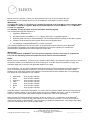
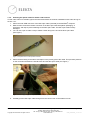
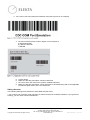
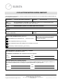
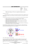
1
IMPORTANT FIELD SAFETY MODIFICATION PRODUCT: 3DLINE DMLC Date: 07-2013 FCO Ref: 200 02 602 032 Device identification of the DMLC IV and DMLC V systems on an Elekta digital linear accelerator with bar codes and a bar code scanner Relates to: Important Field Safety Notice 200 01 602 031 Scope: All 3DLINE DMLC systems on an Elekta Digital Linear Accelerator Description: Device identification of the DMLC IV and DMLC V systems on an Elekta Digital Linear Accelerator with bar codes and a bar code scanner. Technical reference: DMLCLIN-JD EOS 110045 Manpower: One person for 3 hours Tools & test equipment: Standard tool kit for Elekta engineers Parts required: Upgrade kit MRT 19791, which contains: - Bar code scanner hardware kit Bar code label sheets CD with the COPY 1026634 MCS S/W Rev 2.5.4 Note: This FCO does not apply to Agility. DMLC IV and DMLC V systems are not compatible with Agility. __________________________________________________________________ FCO 200 02 602 032 VID: 1.0 Copyright ©2013 Elekta AB. All rights reserved Elekta Ltd, Linac House, Fleming Way, Manor Royal, Crawley, West Sussex RH10 9RR, UK Tel: +44 (0) 1293 544 422 Fax: +44 (0) 1293 654 321 www.elekta.com Page 1 of 30 DID: gPOL0007_2 VID: 01 Contents: 1. Details ......................................................................................................................................... 2 1.1. Prerequisites ...........................................................................................................................................3 1.2. Preparation .............................................................................................................................................3 1.3. Instructions ..............................................................................................................................................5 1.3.1. Attaching the warning label on the DMLC ......................................................................................5 1.3.2. Installing the MCS 2.5.4 patch release ...........................................................................................6 1.3.3. System overview .............................................................................................................................6 1.3.4. Installing the optical cable for the bar code scanner ......................................................................7 1.3.5. Installing the bar code scanner on the digital accelerator fascia, right side (recommended option) 8 1.3.6. Installing the cradle bracket to the fascia .......................................................................................8 ® 1.3.7. Configuring the bar code scanner with MOSAIQ ....................................................................... 14 ® 1.3.7.1. Installing the drivers for the bar code scanner on the MOSAIQ computer ........................ 14 1.3.7.2. Configuring the bar code scanner ........................................................................................ 14 ® 1.3.8. Configuring MOSAIQ ................................................................................................................. 20 1.3.9. Setting the bar code scanner to the correct mode ....................................................................... 22 1.3.10. Restarting the bar code scanner if it discharges completely ....................................................... 23 1. Details This Important Field Safety Modification (IFSM) gives you the instructions to: Add a bar code scanner to your system. Add bar code identification to the related devices. Upgrade to the DMLC control software. Update the Clinical User Manual to include the associated clinical workflow changes. ® Used with the prerequisite upgrades for ERGO++™/ Monaco® and MOSAIQ , the treatment system gives ® dedicated device identification in the DICOM format and in the MOSAIQ characterization file for the device. This makes sure that the correct device is installed and the device identification is related to an interlock in the treatment system. IMPORTANT: It is possible that more than one host machine is configured to use the DMLC system. This can be identified - if there are four mounting holes on the face of the integrated radiation head. Examine all digital linear accelerators at the site for these signs. If more than one host machine is configured, Important Field Safety Notice 200 01 602 031 will apply and also one of the two: The IFSN 200 01 602 031 must be signed for this new machine, or Upgrades must be applied for the new machine to be in compliance with this IFSM (200 02 602 032). FCO 200 02 602 032 VID: 1.0 Copyright ©2013 Elekta AB. All rights reserved Elekta Ltd, Linac House, Fleming Way, Manor Royal, Crawley, West Sussex RH10 9RR, UK Tel: +44 (0) 1293 544 422 Fax: +44 (0) 1293 654 321 www.elekta.com Page 2 of 30 DID: gPOL0007_2 VID: 01 1.1. Prerequisites The digital accelerator must be configured with these products at the defined version level of software: ® MOSAIQ R2.4.1 minimum. ® Monaco 3.3 or ERGO++™ R1.7.7 (or later). Desktop Pro™ R7.01 SP2 or Integrity™ R1.1. The DMLC system workstation must be the HP6600 or Z210. This FCO cannot be applied to other configurations. IMPORTANT: If the configuration is not in compliance with the prerequisites, it is necessary to install or upgrade the products before this FCO installation is done. Elekta recommends that you refer to PMI B437 on the Elekta Marketing web page: Supporting Upgrade Information for Stereotactic Circular Collimators, DMLC MKIV & MKV Device Identification FCO. 1.2. Preparation Before you start the modification, you must find out the information identified in this section. ® The information that follows is necessary for the MOSAIQ characterization file. OIS Support updates the characterization information by remote connection. For each type of Dynamic Multileaf Collimator (3 mm, 5 mm or 7 mm), supply the field size used when the dosimetry data was collected. DMLC system type (mm) Dosimetry Field Size IEC 1217 Scaling - Field size X (mm) IEC 1217 Scaling - Field size Y (mm) Before you set a date to install this FCO upgrade kit, you must schedule a date and time for the OIS Support ® (MOSAIQ ) and supply the above information about the field sizes. Speak to OIS Support through your local free telephone number or use the applicable e-mail address: For Region North America: [email protected] For Region Europe and AFLAME: [email protected] For Region APAC: For Australia and New Zealand: [email protected] If it is necessary to schedule upgrades for the prerequisite configurations, put this quantity of time in the plan: Approximately ten weeks for a hardware upgrade to MOSAIQ or ERGO++™, and Approximately six weeks for a software upgrade. ® To schedule these upgrades, speak to OIS Support through your local free telephone number or use the applicable e-mail address: [email protected] When it is necessary, always refer to the latest Instructions for Use (IFU) manual. Make sure that you have a copy of the IFU before you start the upgrade. ® A hospital physicist must log on to MOSAIQ to give approval of the characterization changes to MOSAIQ after the upgrade and before the treatment of patients. FCO 200 02 602 032 VID: 1.0 Copyright ©2013 Elekta AB. All rights reserved Elekta Ltd, Linac House, Fleming Way, Manor Royal, Crawley, West Sussex RH10 9RR, UK Tel: +44 (0) 1293 544 422 Fax: +44 (0) 1293 654 321 www.elekta.com ® Page 3 of 30 DID: gPOL0007_2 VID: 01 Before you do the upgrade, contact your local business unit to get a copy of Work Instruction MCS254BR_HPZ10+xw6600-ELD11+31 for the installation of the MCS 2.5.4 patch release. IMPORTANT: To support bar codes, it is necessary to schedule the upgrade of the new DMLC control software (MCS) ® ® and ERGO++™/ Monaco together. MCS rejects treatment plans sent from ERGO++™ 1.7.7 / Monaco 3.3 until it is upgraded. The Standard Therapy program cannot be used after the MCS upgrade. The recommended upgrade sequence is: ® 1. Upgrade to MOSAIQ 2.4.1. 2. Schedule the MCS and ERGO++™ 1.7.7 and/or Monaco® 3.3 upgrades together. ® 3. Dosimetry data collection to define MOSAIQ characterization field size settings for the DMLC system. 4. Install the FCO hardware and test it (this uses most of the upgrade time). ® 5. The help desk configures MOSAIQ by remote connection. The hardware upgrade does not have an effect on the performance of the system until the MOSAIQ characterization is updated. The hospital physicist and the local service engineer can schedule the ® characterization of MOSAIQ with remote support at a later date. ® IMPORTANT: ® The characterization of MOSAIQ and a full system integration check are necessary to complete the FCO, and are mandatory before the equipment can be used for clinical treatments. Notes: Before you do the installation, you must buy an extension cable locally. The extension cable connects to one of the two IEC 60320 C13 sockets at the top of the reeling post, or the RIC with an IEC 60320 C14 plug. This extension cable then connects to the applicable adapter on the PSU. As an alternative, you can use an applicable mains power supply socket in the digital accelerator equipment room to connect to the adapter on the PSU. The mains power supply socket must have a switch. Elekta supplies seven Friwo GPP Primary Inlet adapters. The transformers and the adapters are in one packaging box. Select the correct adapter for your location: USA/Japan Korea Argentina India China Brazil UK Friwo number 1827422 Friwo number 1835619 Friwo number 1831610 Friwo number 1831323 Friwo number 1835620 Friwo number 1835621 Friwo number 1827420. Install the cables to minimize the trip hazard. You must show the users the cables and tell them about the trip hazard from trailing cables. If none of these power sources are available, see section 1.3.6 for an alternative where you use a split power cable. Elekta supplies the split power cable in the packaging. ® Make sure that you download all the necessary drivers for section 1.3.7.1. Install them on the MOSAIQ computer before you connect the bar code scanner. Do the procedure in section 1.3.7 and connect the bar ® code scanner directly to the MOSAIQ computer before you install the USB extender. This charges the battery in the bar code scanner while you do the other tasks. FCO 200 02 602 032 VID: 1.0 Copyright ©2013 Elekta AB. All rights reserved Elekta Ltd, Linac House, Fleming Way, Manor Royal, Crawley, West Sussex RH10 9RR, UK Tel: +44 (0) 1293 544 422 Fax: +44 (0) 1293 654 321 www.elekta.com Page 4 of 30 DID: gPOL0007_2 VID: 01 1.3. Instructions Only do this procedure if you are an Elekta engineer who is fully trained on the DMLC system And Elekta digital linear accelerators. 1.3.1. Attaching the warning label on the DMLC 1. Select the Dynamic Multileaf Collimator 2. Make sure that the DMLC surface where you attach the bar code label is clean. 3. Select the correct bar code label from the supplied bar code label sheet (part number 1500927). It must be the same as the correct type of DMLC. 4. Attach the label in the correct position (see Figure 1). Figure 1: Label position FCO 200 02 602 032 VID: 1.0 Copyright ©2013 Elekta AB. All rights reserved Elekta Ltd, Linac House, Fleming Way, Manor Royal, Crawley, West Sussex RH10 9RR, UK Tel: +44 (0) 1293 544 422 Fax: +44 (0) 1293 654 321 www.elekta.com Page 5 of 30 DID: gPOL0007_2 VID: 01 1.3.2. Installing the MCS 2.5.4 patch release Refer to the procedure in the Work Instruction for the MCS 2.5.4 patch release. IMPORTANT: To support bar codes, it is necessary to schedule the upgrade of the new DMLC control software (MCS) and ® ® ERGO++™ / Monaco together. MCS rejects plans sent from ERGO++™ 1.7.7 / Monaco 3.3 until it is upgraded. 1.3.3. System overview See Figure 2 for a technical description of the system. Figure 2: System overview FCO 200 02 602 032 VID: 1.0 Copyright ©2013 Elekta AB. All rights reserved Elekta Ltd, Linac House, Fleming Way, Manor Royal, Crawley, West Sussex RH10 9RR, UK Tel: +44 (0) 1293 544 422 Fax: +44 (0) 1293 654 321 www.elekta.com Page 6 of 30 DID: gPOL0007_2 VID: 01 1.3.4. Installing the optical cable for the bar code scanner If a bar code scanner is installed, ignore the instructions about the scanner installation which follow and go to section 1.3.7. ® 1. Attach the male USB connector of the fiber-optic cable (1027546) to the MOSAIQ computer. 2. Make a sleeve around the female connector of the fiber-optic cable with plastic packaging, or equivalent, and tape to prevent damage to the fiber-optic cable. The fiber-optic cable is easily damaged. 3. You can use a pen to make a loop to attach a draw-string to the end of the fiber-optic cable (see Figure ). Figure 3: Loop and sleeve on the female connector 4. Attach the draw-string to the sleeve and tape it to the primary part of the cable. This prevents pressure on the connection between the interface box and the fiber-optic cable (see Figure ). Figure 4: Draw-string through the loop at the end of the fiber-optic cable 5. Carefully pull the fiber-optic cable through from the control room to the treatment room. FCO 200 02 602 032 VID: 1.0 Copyright ©2013 Elekta AB. All rights reserved Elekta Ltd, Linac House, Fleming Way, Manor Royal, Crawley, West Sussex RH10 9RR, UK Tel: +44 (0) 1293 544 422 Fax: +44 (0) 1293 654 321 www.elekta.com Page 7 of 30 DID: gPOL0007_2 VID: 01 6. Run the cable to behind the digital accelerator (or to a suitable table in the treatment room). If you run the cable to a table, there must be a monitor with an IEC power cable on the table to connect the power supply to the bar code scanner. 1.3.5. Installing the bar code scanner on the digital accelerator fascia, right side (recommended option) To change the cradle to hold the bar code scanner in a vertical position: 1. Use a cross-head screwdriver to turn the Wall Mount Conversion Dial to the correct position to hold the bar code scanner in a vertical position (on a wall). The front latches move out to engage the bottom of the scanner handle. 2. Use a cross-head screwdriver to remove the screws on the rear of the cradle (see Figure 5), and follow the steps in Figure 5 to install the wall cup. Figure 5: Change to a vertical cradle 3. Attach the interface and power cables to the applicable ports. Use force to push them in. 4. Press the cables into the cable grooves. 5. Install the cradle to the cradle bracket (part number 1500125). 1.3.6. Installing the cradle bracket to the fascia The cable routing in the figures in this section is not representative of a device from the manufacturing process. The treatment room monitor (TRM) must be removed before you install the cradle bracket. 1. Hold the TRM and remove the bolts (see Figure 3). Be careful with the cables. FCO 200 02 602 032 VID: 1.0 Copyright ©2013 Elekta AB. All rights reserved Elekta Ltd, Linac House, Fleming Way, Manor Royal, Crawley, West Sussex RH10 9RR, UK Tel: +44 (0) 1293 544 422 Fax: +44 (0) 1293 654 321 www.elekta.com Page 8 of 30 DID: gPOL0007_2 VID: 01 Figure 3: Bolts for the treatment room monitor 2. Remove the TRM. 3. Remove the second set of 4 bolts (see Figure 7). Figure 7: Second set of bolts 4. Lift the fascia panel. 5. Put the cradle bracket on the lower fascia panel (see Figure 8). FCO 200 02 602 032 VID: 1.0 Copyright ©2013 Elekta AB. All rights reserved Elekta Ltd, Linac House, Fleming Way, Manor Royal, Crawley, West Sussex RH10 9RR, UK Tel: +44 (0) 1293 544 422 Fax: +44 (0) 1293 654 321 www.elekta.com Page 9 of 30 DID: gPOL0007_2 VID: 01 Figure 8: Cradle bracket on lower fascia panel Figure 9: Cradle for the bar code scanner attached to the cradle bracket 6. Route the cable for the handheld controller again from the left hole in the bracket (viewed from the back) to the right hole. 7. Route the USB cable for the bar code scanner through the hole nearest the bar code scanner (see Figure 4 and Figure 5). FCO 200 02 602 032 VID: 1.0 Copyright ©2013 Elekta AB. All rights reserved Elekta Ltd, Linac House, Fleming Way, Manor Royal, Crawley, West Sussex RH10 9RR, UK Tel: +44 (0) 1293 544 422 Fax: +44 (0) 1293 654 321 www.elekta.com Page 10 of 30 DID: gPOL0007_2 VID: 01 Figure 4: Route the USB cable Figure 5: Cable in right bracket hole 8. Install the panel again. 9. Install the bolts and TRM again. 10. Connect the external PSU (1026959) to the small box on the female end of the fiber-optic cable extender. 11. Connect the split power cable (1028409, part of the upgrade kit) to the mains power supply for the TRM (see Figure 6). FCO 200 02 602 032 VID: 1.0 Copyright ©2013 Elekta AB. All rights reserved Elekta Ltd, Linac House, Fleming Way, Manor Royal, Crawley, West Sussex RH10 9RR, UK Tel: +44 (0) 1293 544 422 Fax: +44 (0) 1293 654 321 www.elekta.com Page 11 of 30 DID: gPOL0007_2 VID: 01 Figure 6: Split power cable 12. Connect one of the female connectors of the split power cable to the TRM (see Figure 7). 13. Connect the other female connector of the split power cable to the PSU for the fiber-optic cable. Figure 7: Split power cable diagram 14. After you pulled the fiber-optic cable through the cable ducts, put the end behind the fascia near the selected TRM. Install it to the frame with cable ties (see Figure 8). Be careful not to attach the cable tie too tightly. FCO 200 02 602 032 VID: 1.0 Copyright ©2013 Elekta AB. All rights reserved Elekta Ltd, Linac House, Fleming Way, Manor Royal, Crawley, West Sussex RH10 9RR, UK Tel: +44 (0) 1293 544 422 Fax: +44 (0) 1293 654 321 www.elekta.com Page 12 of 30 DID: gPOL0007_2 VID: 01 Figure 8: Cable tie to frame 15. Use cable ties to attach the power supply cable to the extension cable (see Figure 9). Figure 9: Cable tie for the power cable FCO 200 02 602 032 VID: 1.0 Copyright ©2013 Elekta AB. All rights reserved Elekta Ltd, Linac House, Fleming Way, Manor Royal, Crawley, West Sussex RH10 9RR, UK Tel: +44 (0) 1293 544 422 Fax: +44 (0) 1293 654 321 www.elekta.com Page 13 of 30 DID: gPOL0007_2 VID: 01 1.3.7. Configuring the bar code scanner with MOSAIQ ® ® 1.3.7.1. Installing the drivers for the bar code scanner on the MOSAIQ computer ® Do not connect the bar code scanner and cradle (1024731) to the MOSAIQ /extension terminal USB port until the drivers are correctly installed. 1. Make sure that the usbser.sys file is in c:\Windows\System32\drivers If it is not, search for this file in drive C and copy it to c:\Windows\System32\drivers. The usbser.sys file can be found as follows: For Windows 7 (x86 32bit): C:\Windows\System32\DriverStore\FileRepository\mdmcpq.inf_x86_neutral_XXXXXXXXXX (archive file) For Windows 7 (x64 64bit): C:\Windows\System32\DriverStore\FileRepository\mdmcpq.inf_amd64_neutral_XXXXXXXXXX (archive file) 2. Make a new folder on the desktop for downloaded scanner drivers. 3. Save a copy of usbcdc.inf to the new folder. You can find this file at: ftp://ftp2.impac.com/eng/install/barcoding/usbcdc.inf, or https://docs.symbol.com/downloads/usbcdc.inf 4. Save a copy of usbcdcraw.inf to the new folder. You can find this file at: ftp://ftp2.impac.com/eng/install/barcoding/usbcdcraw.inf, or https://docs.symbol.com/downloads/usbcdcraw.inf ® 5. Connect the bar code scanner to the MOSAIQ computer. Note: When the battery is fully discharged, it can be 30 minutes before you can use the bar code scanner. 1.3.7.2. Configuring the bar code scanner Configure the bar code scanner as a serial device: 1. When the bar code scanner is sufficiently charged, press ENT on the bar code scanner. 2. Do a scan of the Set Factory Defaults code from the bar code scanner manual (see Figure 10 for an example. If you do not have the documentation, go to http://support.symbol.com and search for the MT2070/MT2090 User Guide.) Figure 10: Set Factory Defaults bar code example 3. Do a scan of the PAIR code in the cradle to make sure that the bar code scanner is paired with the cradle. It is possible that this step is not necessary for bar code scanners that are connected directly to the USB cable. 4. On the scanner, press Close to get back to the Home screen. 5. Use the 4-way navigation key to select 6 – Config then press ENT. 6. Use the 4-way navigation key to select 5 – Configure USB then press ENT. 7. Use the 4-way navigation key to select Retail CDC (STB2078 Only) – Config then press ENT. 8. Select Close. 9. Select 0 – Up then ENT. 10. Select 1 – Scan Item then ENT. The operating system shows a new hardware was found message. FCO 200 02 602 032 VID: 1.0 Copyright ©2013 Elekta AB. All rights reserved Elekta Ltd, Linac House, Fleming Way, Manor Royal, Crawley, West Sussex RH10 9RR, UK Tel: +44 (0) 1293 544 422 Fax: +44 (0) 1293 654 321 www.elekta.com Page 14 of 30 DID: gPOL0007_2 VID: 01 11. If the system shows a dialog box to update the driver, select to update the drivers manually. 12. If the system does not show a dialog box to update the driver, do these steps: Note: ® ® The steps that follow apply to Windows 7. For Windows XP, the steps are almost equivalent. For ® more information about the Windows XP installation, go to https://docs.symbol.com/ReleaseNotes/USBCDCINF%20Release%20Notes.pdf (and http://www.microchip.com/forums/m488342-print.aspx) ® a. Open the Windows Device Manager. b. In the Other devices folder, right-click Symbol Bar Code Scanner, and then select Update Driver Software (see Figure 11). Figure 11: Symbol Bar Code Scanner in Other devices Figure 18: Unknown device in Other devices c. If Unknown device appears in Other devices (see Figure 18), right-click Unknown device, and then select Update Driver. The Update Driver Software dialog box appears (see Figure 12). FCO 200 02 602 032 VID: 1.0 Copyright ©2013 Elekta AB. All rights reserved Elekta Ltd, Linac House, Fleming Way, Manor Royal, Crawley, West Sussex RH10 9RR, UK Tel: +44 (0) 1293 544 422 Fax: +44 (0) 1293 654 321 www.elekta.com Page 15 of 30 DID: gPOL0007_2 VID: 01 Figure 12: Searching for driver software d. Click Browse my computer for driver software. e. In the dialog box that appears, click Let me pick from a list of device drivers on my computer (see Figure 13). Figure 13: Browse for driver software on your computer f. In the Common hardware types list, select Ports (COM & LPT) (see Figure 14). FCO 200 02 602 032 VID: 1.0 Copyright ©2013 Elekta AB. All rights reserved Elekta Ltd, Linac House, Fleming Way, Manor Royal, Crawley, West Sussex RH10 9RR, UK Tel: +44 (0) 1293 544 422 Fax: +44 (0) 1293 654 321 www.elekta.com Page 16 of 30 DID: gPOL0007_2 VID: 01 Figure 14: Select Ports (COM & LPT) g. Click Next. h. In the dialog box that appears, click Have Disk (see Figure 15). Figure 15: Device driver selection i. j. Browse to the folder that has the usbcdc.inf and usbcdcraw.inf files that you saved earlier. Select the file. FCO 200 02 602 032 VID: 1.0 Copyright ©2013 Elekta AB. All rights reserved Elekta Ltd, Linac House, Fleming Way, Manor Royal, Crawley, West Sussex RH10 9RR, UK Tel: +44 (0) 1293 544 422 Fax: +44 (0) 1293 654 321 www.elekta.com Page 17 of 30 DID: gPOL0007_2 VID: 01 k. Click OK. A dialog box appears with the hardware device (see Figure 16). Figure 16: Driver selection l. Click Next. ® m. If a Windows security warning appears about the publisher of the driver, ignore the warning and continue to install the driver. A driver successfully installed message is displayed. The Symbol Bar Code Scanner item is displayed in Ports (COM & LPT in the Device Manager The COM port used is also displayed (see Figure 17, in the example, it was assigned as COM6). Figure 17: COM port assignment n. To select a COM port, right-click the Symbol Bar Code Scanner, and then click Properties. The Properties dialog box appears. o. Click the Port Settings tab. FCO 200 02 602 032 VID: 1.0 Copyright ©2013 Elekta AB. All rights reserved Elekta Ltd, Linac House, Fleming Way, Manor Royal, Crawley, West Sussex RH10 9RR, UK Tel: +44 (0) 1293 544 422 Fax: +44 (0) 1293 654 321 www.elekta.com Page 18 of 30 DID: gPOL0007_2 VID: 01 Figure 185: Properties dialog box p. Click Advanced (see Figure 18). The Advanced Settings for COM<x> dialog box appears (see Figure 19). Figure 19: COM port selection q. Select the necessary COM port for the bar code scanner. In this example, COM3 is selected ® (MOSAIQ accepts COM1 through to COM4). The Symbol Bar Code Scanner is then assigned to the selected COM port (see Figure 20). FCO 200 02 602 032 VID: 1.0 Copyright ©2013 Elekta AB. All rights reserved Elekta Ltd, Linac House, Fleming Way, Manor Royal, Crawley, West Sussex RH10 9RR, UK Tel: +44 (0) 1293 544 422 Fax: +44 (0) 1293 654 321 www.elekta.com Page 19 of 30 DID: gPOL0007_2 VID: 01 Figure 20: Selected COM port for the bar code scanner 1.3.8. Configuring MOSAIQ ® ® After the bar code scanner is configured, set up MOSAIQ (versions 2.41.01 F1+ and 2.50.01 I5+ only) to communicate with the bar code scanner through the serial port: ® 1. Start MOSAIQ . 2. On the menu bar, click File > System Utilities > Barcode Configuration (see Figure 21). Figure 21: MOSAIQ® Barcode Configuration The Barcode Configuration dialog box appears (see Figure 22). FCO 200 02 602 032 VID: 1.0 Copyright ©2013 Elekta AB. All rights reserved Elekta Ltd, Linac House, Fleming Way, Manor Royal, Crawley, West Sussex RH10 9RR, UK Tel: +44 (0) 1293 544 422 Fax: +44 (0) 1293 654 321 www.elekta.com Page 20 of 30 DID: gPOL0007_2 VID: 01 Figure 22: Serial port configuration 3. Click Serial Port Configuration. The Barcode Serial Port Configuration dialog box appears (see Figure 23). Figure 23: Barcode Serial Port Configuration dialog box 4. On the menu bar, click Add. The Barcode Serial Port Configuration dialog box appears (see Figure 24). Figure 24: Serial port selection in MOSAIQ® 5. In the Workstation box, type the workstation name (the workstation IP address can also be used). 6. Select the COM port to use. FCO 200 02 602 032 VID: 1.0 Copyright ©2013 Elekta AB. All rights reserved Elekta Ltd, Linac House, Fleming Way, Manor Royal, Crawley, West Sussex RH10 9RR, UK Tel: +44 (0) 1293 544 422 Fax: +44 (0) 1293 654 321 www.elekta.com Page 21 of 30 DID: gPOL0007_2 VID: 01 7. Click OK. ® 8. The system updates the MOSAIQ configuration (see Figure 25). Figure 25: Updated configuration The bar code scanner is prepared for operation. 9. If it is necessary, close the Barcode Serial Port Configuration and Barcode Configuration dialog boxes. 1.3.9. Setting the bar code scanner to the correct mode ® After the bar code scanner is configured in MOSAIQ , it must be set to the correct mode: 1. Do scans of the three bar codes in Figure 26 in this sequence: a) SCAN OPTIONS b) DATA SUFFIX c) ENTER. Note: These three bar codes are in the documentation for the bar code scanner that is supplied in the upgrade kit. If you do not have the documentation, go to http://support.symbol.com and search for the MT2070/MT2090 User Guide. Figure 26: Configuration of the bar code scanner mode 2. Load a patient. FCO 200 02 602 032 VID: 1.0 Copyright ©2013 Elekta AB. All rights reserved Elekta Ltd, Linac House, Fleming Way, Manor Royal, Crawley, West Sussex RH10 9RR, UK Tel: +44 (0) 1293 544 422 Fax: +44 (0) 1293 654 321 www.elekta.com Page 22 of 30 DID: gPOL0007_2 VID: 01 3. Make sure that the prescription cannot be delivered. 4. Do a scan of the bar code on the DMLC system. 5. Make sure that the prescription can be delivered. Do troubleshooting and do the applicable procedures again if this is not a successful test. 1.3.10. Restarting the bar code scanner if it discharges completely The bar code scanner must be charged for a minimum of 30 minutes before you can use it. If there is an error when the bar code is transmitted to the host, it can be necessary to do a ‘warm reboot’. To do a warm reboot: 1. Hold button 2 on the bar code scanner and then at the same time press the scanner trigger for 5 seconds. The bar code scanner restarts. Note: If you hold button 2 and the trigger for 10 seconds, the bar code scanner fully resets. The bar code scanner configuration is erased and you have to do the procedure to configure it again. 2. When it is fully prepared, do a check that the bar code scanner operates correctly. There are no more steps to this upgrade. Procedure: 1 2 3 4 5 6 Read the instructions in the upgrade kit before you start the change. Make sure that all the parts on the dispatch list are delivered. Use the drawing(s) supplied and/or the installation instructions and follow the step by step instructions to do the modification. When the modification is complete, update the modification record label on the applicable assembly with the ECO number in the Technical Reference Number if applicable. If applicable, put the modification instructions and the FCO in the service documentation. If it is necessary by local procedures, make sure that all documentation is completed fully and sent to the local Elekta Office and/or representative to add to the Configuration Database. Make sure that parts sent back to Elekta Limited are in the correct packaging and sent immediately with a Returns Authorization (RA) number. You can get a RA number from the Elekta spare parts department. FCO 200 02 602 032 VID: 1.0 Copyright ©2013 Elekta AB. All rights reserved Elekta Ltd, Linac House, Fleming Way, Manor Royal, Crawley, West Sussex RH10 9RR, UK Tel: +44 (0) 1293 544 422 Fax: +44 (0) 1293 654 321 www.elekta.com Page 23 of 30 DID: gPOL0007_2 VID: 01 IMPORTANT 7 Make sure that the section of this FCO for the new clinical workflow instructions is removed and put in the Important Notice section of the Clinical User Manual. 8 On the FCO Action Notification Report, ensure you record the following information: Host Machine make and Model Host Machine Control System Type and Software Revision Treatment Planning System Type and Software Revision OIS System Type and Software Revision. NOTE: Parts that are in contact with body fluids (for example, top of treatment table) or are a radiation hazard must have a signed Declaration of Contamination Status included with the part BEFORE it is sent back to Elekta. FCO 200 02 602 032 VID: 1.0 Copyright ©2013 Elekta AB. All rights reserved Elekta Ltd, Linac House, Fleming Way, Manor Royal, Crawley, West Sussex RH10 9RR, UK Tel: +44 (0) 1293 544 422 Fax: +44 (0) 1293 654 321 www.elekta.com Page 24 of 30 DID: gPOL0007_2 VID: 01 Date: FCO Ref: 07-2013 200 02 602 032 Changes to your system to improve the safe operation of DMLC IV and DMLC V systems It is possible for errors to occur in the clinical workflow for the operation of 3DLINE DMLC systems. This upgrade kit, when used in conjunction with the pre-requisite changes for TPS and OIS will help to prevent these possible errors: ID Function Possible Error 1 The TPS automatically transfers the DMLC identifier to the R&V system and the R&V system automatically loads the DMLC identifier. This prevents: No DMLC system installation at the necessary time. Each DMLC is identified by a unique bar code. This prevents: No DMLC system installation at the 2 necessary time. A diaphragm size incorrectly set in the TPS. 3 If a DMLC is indicated for use for a treatment, the correct bar code scan data must be available before treatment is permitted by the system. This prevents: No DMLC system installation at the necessary time. 4 MOSAIQ® does a check that the prescribed diaphragm settings are the same as for the DMLC, and prevents treatment delivery if it is not correct. This prevents: A diaphragm size incorrectly set in the TPS. 5 The diaphragm settings for the DMLC cannot be changed in MOSAIQ®. This prevents: A diaphragm size incorrectly set in the TPS. Standard Therapy must be blocked by DMLC MCS. This prevents: A diaphragm incorrectly set in Standard Therapy The system must prevent treatment delivery if the DMLC cannot find the EPID file. This prevents: A diaphragm incorrectly set in Standard Therapy Different patients and/or beams selected in MOSAIQ® and MCS. 6 7 FCO 200 02 602 032 VID: 1.0 Copyright ©2013 Elekta AB. All rights reserved Elekta Ltd, Linac House, Fleming Way, Manor Royal, Crawley, West Sussex RH10 9RR, UK Tel: +44 (0) 1293 544 422 Fax: +44 (0) 1293 654 321 www.elekta.com Page 25 of 30 DID: gPOL0007_2 VID: 01 DMLC system workflow changes with the bar code scanner in operation The DICOM data that is exported from the treatment planning system to MOSAIQ® includes an accessory code for the DMLC system. After you import the code, the field size of the digital accelerator diaphragms is fixed for the applicable DMLC system size, and you cannot change this value. This prevents irradiation of a field size that is larger than the maximum field size of the DMLC system. Before treatment, you must do a scan of the correct bar code on the applicable DMLC system to clear the accessory inhibit. In the updated system, it is not possible to deliver treatments to patients in Standard Therapy mode. All treatments must be completed with the R&V system. New Clinical Workflow This is the new clinical workflow: 1. Complete the plan in ERGO++™ with the applicable size of DMLC system, in compliance with the usual hospital protocol. 2. Export the plan to MOSAIQ®. This automatically adds the accessory code to the applicator/wedge field (in the treatment definition window) of the treatment field and sets the field size to the correct field size for the DMLC. 3. Prepare the plan in MOSAIQ® in compliance with the usual hospital protocols. 4. Load the patient and field in MOSAIQ® for treatment. 5. Set up the patient on the treatment table in compliance with the usual hospital protocols. WARNING Do not do a scan of the bar code until after you attach the dynamic multileaf collimator. If you ignore this warning, you can cause clinical mistreatment. 6. With the bar code scanner, do a scan of the bar code on the DMLC system. This step clears the inhibit in MOSAIQ® when the bar code which was read and the prescribed accessory code agree. 7. Deliver the treatment to the patient in compliance with the usual hospital protocols. The DMLC system size used is recorded in the treatment record in MOSAIQ® as an accessory in the applicator/wedge field. Follow the necessary procedures of the manufacturer of the bar code scanner supplied with the upgrade kit. Pacemakers The Motorola bar code scanner can have an effect on pacemakers because of electronic interference. Refer to the documentation from the manufacturer of the bar code scanner for more information. FCO 200 02 602 032 VID: 1.0 Copyright ©2013 Elekta AB. All rights reserved Elekta Ltd, Linac House, Fleming Way, Manor Royal, Crawley, West Sussex RH10 9RR, UK Tel: +44 (0) 1293 544 422 Fax: +44 (0) 1293 654 321 www.elekta.com Page 26 of 30 DID: gPOL0007_2 VID: 01 If a person has a pacemaker, make sure that: 1. You follow the necessary procedures of the pacemaker manufacturer. 2. You keep a minimum distance of 15 cm between the bar code scanner and the pacemaker to prevent electronic interference between the devices. This is recommended by the pacemaker manufacturers. Restarting the bar code scanner after the digital accelerator is switched off If the power supply to the bar code scanner is from the digital accelerator, when the digital accelerator is switched off the bar code scanner discharges. This is because it is energized from the treatment room monitor that is switched off. When the digital accelerator is switched on, it is possible that the bar code scanner is fully discharged. It must be charged for a minimum of 30 minutes before you can use it. When you switch on the digital accelerator, make sure that the bar code scanner clears the bar code inhibit. If it does not, you must do a ‘warm restart’ of the bar code scanner. This prevents an error that can occur when the bar code is transmitted to the host. To do a warm restart: 1. Hold the button identified by 2 on the bar code scanner and then at the same time press the scanner trigger for 5 seconds. The bar code scanner restarts. Note: If you hold the 2 button and the scanner trigger for 10 seconds, the bar code scanner will fully reset. The bar code scanner configuration is erased and you have to do the procedure to configure it again. 2. When it is fully prepared, do a check that the bar code scanner operates correctly. Configuring the bar code scanner after the bar code scanner is fully reset This procedure is only necessary if there are no configuration settings for the bar code scanner. 1. Do a scan of the Set Factory Defaults code from the bar code scanner manual (see Figure 1 for an example). 2. Do a scan of the PAIR code in the cradle to make sure the bar code scanner is paired with the cradle. It is possible that this step is not necessary for bar code scanners that are connected directly to the cradle by the USB cable. FCO 200 02 602 032 VID: 1.0 Copyright ©2013 Elekta AB. All rights reserved Elekta Ltd, Linac House, Fleming Way, Manor Royal, Crawley, West Sussex RH10 9RR, UK Tel: +44 (0) 1293 544 422 Fax: +44 (0) 1293 654 321 www.elekta.com Page 27 of 30 DID: gPOL0007_2 VID: 01 3. Do a scan of the CDC COM Port Emulation code (see Figure 2 for an example). 4. Do scans of the three bar codes in Figure 3 in this sequence: a) SCAN OPTIONS b) <DATA><SUFFIX> c) ENTER. 5. 6. 7. 8. Load a patient. Make sure that the prescription cannot be delivered. Do a scan of the bar code on the dynamic multileaf collimator. Make sure that the prescription can be delivered. Do troubleshooting and do the applicable procedures again if this is not a successful test. Safety reference: The following warnings and cautions are associated with this notice: 1. Do not do a scan of the bar code until after you attach the dynamic multileaf collimator. If you ignore this warning, you can cause clinical mistreatment. FCO 200 02 602 032 VID: 1.0 Copyright ©2013 Elekta AB. All rights reserved Elekta Ltd, Linac House, Fleming Way, Manor Royal, Crawley, West Sussex RH10 9RR, UK Tel: +44 (0) 1293 544 422 Fax: +44 (0) 1293 654 321 www.elekta.com Page 28 of 30 DID: gPOL0007_2 VID: 01 Procedure: 1 2 3 4 5 6 Read the instructions in the modification kit (ModKit) before you start to implement the change. Make sure that all the parts on the dispatch list are delivered. Use the drawing(s) supplied and/or the installation instructions, and follow the step by step instructions and implement the modification. When the modification is complete update the modification record label on the applicable assembly with the ECO number in the Technical Reference Number, if applicable. If applicable, put the modification instructions and the FCO in the service documentation for reference. If required by local procedures, make sure that all paperwork is completed in full and sent to the local Elekta Office and/or representative, to add to the Configuration Database. Make sure that any parts to be returned to Elekta Limited are packaged correctly, and dispatched without delay using a Returns Authorization (RA) number. An RA number is supplied by the Spares Department on request. NOTE: Parts that have come into contact with body fluids (for example, top of treatment table) or constitute a radiation hazard must have a signed Declaration of Contamination Status included with the part BEFORE it is returned. FCO 200 02 602 032 VID: 1.0 Copyright ©2013 Elekta AB. All rights reserved Elekta Ltd, Linac House, Fleming Way, Manor Royal, Crawley, West Sussex RH10 9RR, UK Tel: +44 (0) 1293 544 422 Fax: +44 (0) 1293 654 321 www.elekta.com Page 29 of 30 DID: gPOL0007_2 VID: 01 FCO ACTION NOTIFICATION REPORT <Give this Notice to the customer, and then complete and return this report to your local Elekta Office or Representative for the Configuration Database.> Classification: Important Field Safety Modification FCO description: Device identification of the DMLC IV and DMLC V systems on an Elekta Digital Linear Accelerator with a bar code and a bar code scanner Scope: All 3DLINE DMLC systems on an Elekta digital linear accelerator FCO Ref: 200 02 602 032 Hospital: Device Serial No: (eg linac - if applicable) Location or Site No: Action on this unit/device was: (select one) Completed as per instructions on: <date day/month/year> Note: If you use a work-order in the CLM configuration database, then you do not have to complete this section. The work-order will be used to add the information to the system. Not completed because: (give reasons) Not completed because the unit/device is in storage (if applicable). Refused by customer because: (give reasons) Acknowledgement / Acceptance / Refusal by customer: This notification to be signed by the customer. The REASON and PURPOSE of this modification has been explained. Name: Title: Signature: Date: Acknowledgement by installing engineer: This section is signed by the Elekta representative, for example, Installation Engineer, Service Engineer, Distributor, or who installed the modification kit, for example, a hospital representative or system operator. Name: Title: Signature: Date: FCO 200 02 602 032 VID: 1.0 Copyright ©2013 Elekta AB. All rights reserved Elekta Ltd, Linac House, Fleming Way, Manor Royal, Crawley, West Sussex RH10 9RR, UK Tel: +44 (0) 1293 544 422 Fax: +44 (0) 1293 654 321 www.elekta.com Page 30 of 30 DID: gPOL0007_2 VID: 01