1
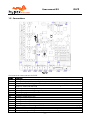
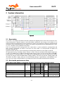
Hypex Electronics BV
Kattegat 8
9723 JP Groningen, The Netherlands
+31 50 526 4993
[email protected]
www.hypex.nl
User Manual R3
Digital Loudspeaker Cross-over Platform
(DLCP)
User manual R3
DLCP
Table of contents
Table of contents ............................................................................................................................................. 2
1 Product description .................................................................................................................................. 3
1.1
Type remarks ................................................................................................................................... 3
1.2
Highlights ......................................................................................................................................... 3
1.3
Features ............................................................................................................................................ 3
1.4
Applications ..................................................................................................................................... 4
1.5
Connections ..................................................................................................................................... 5
2 System information ................................................................................................................................. 6
2.1
Description ....................................................................................................................................... 6
2.2
Brief audio performance data ........................................................................................................ 6
2.3
Recommended Operating Conditions ........................................................................................... 7
2.4
Hardware Architecture .................................................................................................................... 7
2.4.1
Analogue input ........................................................................................................................ 7
2.4.2
Digital input ............................................................................................................................. 7
2.4.3
Digital output ........................................................................................................................... 7
2.4.4
DSP ............................................................................................................................................ 7
2.4.5
Microcontroller ......................................................................................................................... 7
2.5
Add-ons ............................................................................................................................................ 8
2.5.1
DLCP Input board ..................................................................................................................... 8
2.5.2
DLCP Control board ............................................................................................................... 11
3 Product overview .................................................................................................................................... 13
3.1
DLCP setups ................................................................................................................................... 13
3.1.1
Example 1: DLCP as preamplifier ......................................................................................... 13
3.1.2
Example 2: DLCP as active loudspeaker filter ..................................................................... 14
3.2
Application notes........................................................................................................................... 15
4 Hypex Filter Design ................................................................................................................................ 16
4.1
Target response ............................................................................................................................. 16
4.2
Driver correction ............................................................................................................................ 16
4.3
Crossover design ........................................................................................................................... 16
4.4
Software installation ..................................................................................................................... 16
4.5
Control panel .................................................................................................................................. 17
4.5.1
Input options .......................................................................................................................... 17
4.6
Filter design.................................................................................................................................... 18
4.6.1
Graph Area ............................................................................................................................. 19
4.6.2
Filter Definition Area ............................................................................................................. 19
4.6.3
Settings window .................................................................................................................... 20
4.6.4
Link Channels window ........................................................................................................... 20
4.6.5
DLCP options window ............................................................................................................ 21
4.6.6
Work flow................................................................................................................................ 21
4.6.7
Designing filters ..................................................................................................................... 23
4.6.8
Download ................................................................................................................................ 23
4.6.9
Save files ................................................................................................................................. 23
4.7
Firmware update............................................................................................................................ 24
4.7.1
DLCP ........................................................................................................................................ 24
4.7.2
Control board ......................................................................................................................... 24
4.8
Filter example ................................................................................................................................ 25
4.8.1
The substrate ......................................................................................................................... 25
4.8.2
The filters ............................................................................................................................... 25
4.8.3
Result ...................................................................................................................................... 26
5 Dimensions ............................................................................................................................................. 28
5.1
DLCP ................................................................................................................................................ 28
5.2
DLCP input board ........................................................................................................................... 29
5.3
DLCP control board ........................................................................................................................ 29
6 Revision History ..................................................................................................................................... 30
-2-
User manual R3
DLCP
1 Product description
1.1 Type remarks
Use only a version 2.8 or higher of the Hypex Filter Design program! In earlier versions the DLCP
is not yet implemented.
Static electricity can cause damage to this product.
The first time the DLCP is used all biquads are zero, so there are no filters installed.
Connecting any speakers and audio input at this point may cause some damage to
them.
Take notice on what changes you make, to prevent a setup which can damage your
speakers!
After updating the firmware please use the combining PC software downloaded from
our website, www.hypex.nl
…………………………………..
The purpose of this manual is to describe the functionality and contents of the Hypex Digital loudspeaker cross-over Platform (DLCP) from Hypex. This document includes instructions for operating
the board and descriptions of the hardware features. For more detailed information on connectors
and specifications one should read the datasheet.
Before reading this manual, make sure you have the latest version. The latest version can be found
at www.hypex.nl
1.2 Highlights
Fully user customized filtering
Great audio performance
Field updatable firmware
Current-mode serial I/F
USB audio
Dimensions only: 110mm x 110mm x 30mm
Low weight: 140g
1.3 Features
Compact design
Personal Computer controlled
Input sample rates up to 192kHz
Analogue and digital inputs
Digital balanced audio loop-through
Low-jitter discrete clock oscillator
Balanced audio in and out
Six channel active filtering
Fully user-configurable filters
Firmware updateable by USB
Separate Clock and Data Paths
Six user configurable analogue balanced outputs
High-Level outputs permit direct interface with NC400/
buffered UcD™ ST and HG power amplifiers
Analogue input gain trim
9 local DAC regulators
IIR filtering
-3-
User manual R3
DLCP
96kHz sampling rate
Can be used as a digital pre amplifier
Stand-by mode
On board Molex® Microfit® output connectors
Connector for external Led.
Optional control board with IR receiver for IR control, LCD display and buttons
Optional input board to increase the number of analogue stereo inputs to 4
Link communication (only with two or more modules and in combination with a controller)
1.4 Applications
High-end consumer audio
Digital pre amplifier
Active speakers up to six-way
Three-way stereo active system
PA Systems
Studio Monitors
With 2 modules it is also possible to set up an:
Active 12-channel system
Active 6-way stereo system
Setups are further explained in the “Product overview” chapter.
-4-
User manual R3
DLCP
1.5 Connections
Figure 1
Overview of the connectors on the DLCP
Name
Function
Analogue audio output header (contains all audio outputs from J10-J15)
J1
Analogue/Digital audio in and digital output header
J2
I/O connector (USB, Relay, Control)
J3
DLCP SMPS power supply connector (Do not use when a Hypex SMPS module auxiliary
J4
output is connected with J16)
Gain adjust header analogue left input
J5
Gain adjust header analogue right input
J8
Standby supply connector
J17
Analogue audio output ch1
J10
Analogue audio output ch2
J11
Analogue audio output ch3
J12
Analogue audio output ch4
J13
Analogue audio output ch5
J14
Analogue audio output ch6
J15
Power Supply connector Hypex SMPS (Do not use when J4 is connected to another supply)
J16
LED connector
J7
Microcontroller & DSP programmer connector, not used by user
J6
Jumpers for programming or normal operation, not used by user
JP5
-5-
User manual R3
DLCP
2 System information
Figure 2
2.1 Description
The “DLCP” is a complete hardware/firmware platform for digitally filtered and corrected active multiway loudspeakers. Digital response correction allows significant extra degrees of freedom in the
acoustic design of a loudspeaker. Driver parameters can be selected for best efficiency and distortion
instead of electrical damping, and the cabinet can now be fully optimized for radiation pattern. Figure 2 is a schematic representation of the DLCP.
A PC can control the DLCP through USB. This connection is used to upload the configuration and
filter settings, USB-audio can also be send thru the same cable. It is also possible to update the
firmware through USB.
Optional remote control is effected through a 4mA optically isolated current-mode serial link.
All signal processing, including volume control, is done using the on-board DSP (digital signal processor). The module has six Molex® Microfit® audio outputs, which can be used to connect NC400 /
buffered UcD™ ST and HG modules. The supply can be provided by the new DLCP SMPS or the auxiliary output of a Hypex Switched Mode Power Supply module. The DLCP can go into standby mode and
shut down the power supply, when an external standby voltage is applied and a controlboard is present. You can create a chain of DLCP’s (up to 6!) to increase the number of DSP filtered channels.
2.2 Brief audio performance data
MBW=20kHz (20Hz-20Khz), unweighted, all filters set to unity, unless otherwise noted
Item
Symbol
Min
Typ
Max Unit Notes
1)
Input level
24.25
Gain adjust 0dB
17.95
Gain adjust +6dB
dBu
VIN
12
Gain adjust +12dB
9
Gain adjust +15dB
Output level
2.59
V
0 dBFS
VOUT
DSP sampling rate
Fs
93.75
kHz
ADC sampling rate
Fs
93.75
kHz
Supported digital sampling rates
Fs
32, 44.1, 48, 88.2, 96, kHz All input rates con192
verted to 93.75kHz
Note 1: See J5/J8 in Connections
-6-
User manual R3
2.3
DLCP
Recommended Operating Conditions
Item
Supply voltage
Symbol
Min
1)
15.5
Typ
18
Max
2)
26
Unit
Vdc
Notes
Positive and negative supply voltage
Note 1: Unit shuts down when the positive rail drops below 15V.
Note 2: Especially on high supply voltages; make sure there’s enough airflow to cool the regulators.
2.4 Hardware Architecture
2.4.1
Analogue input
The DLCP has two (stereo) analogue balanced audio inputs. The analogue input signal is buffered
and amplified by a single-stage, fully differential programmable gain amplifier and then converted to
digital by the ADC. The ADC is always directly clocked by the on-board oscillator, a low noise Colpitts
oscillator with a locally regulated supply, causing less jitter. After the analogue to digital conversion
the signal is processed by the DSP.
2.4.2
Digital input
The DLCP contains four separate digital inputs, permitting the use of different interconnection
standards (AES/EBU and S/PDIF). Optimal clock quality is insured by routing the clock through separate IC’s from the data signals, and by local regulation of all supplies on the AES input circuit.
Incoming AES / S/PDIF is send to the DSP through an asynchronous sample rate converter (ASRC) to
reduce jitter.
When the input is set to “Auto detect”, the ASRC chip scans its inputs for whichever digital signal is
present. The input source is automatically switched to digital when present, using the priority described below. If the digital audio source is removed, the input will be automatically switched back
the last chosen analogue input.
Auto detect input priority high to low:
1) AES
2) SPDIF
3) USB_audio
4) Optical
2.4.3
Digital output
The DLCP contains two separate digital outputs, AES/EBU and S/PDIF. The selected digital input is
directly send to both digital outputs. (Without filtering)
2.4.4
DSP
The DSP filtering can be changed by Hypex Filter Design (HFD) software. The digital outputs from the
DSP are fed to the DACs. The DAC chip receives data from the DSP and clock either from the crystal
oscillator or from the digital input section. The digital signal is then converted to analogue by the
DAC. The post filter is executed twice, providing a balanced load to the DAC and delivering a high
output level to the power amplifier.
2.4.5
Microcontroller
A microcontroller controls the DSP and other ICs and I/O’s on the PCB, communicates with the control board, PC and/or other DLCP’s that may be attached. When the module is powered on it will automatically start up with the last settings. All settings, like volume and source selection, are stored
after a change is made.
-7-
User manual R3
DLCP
2.5 Add-ons
2.5.1
DLCP Input board
Figure 3
The DLCP can be used as a digital pre amplifier when the optional “DLCP input board” is bought. This
input board can be connected to the DLCP with only 2 flat cables. You can increase the number of
analogue inputs to 4 balanced stereo analogue inputs. It has four digital inputs; USB audio, AES
1
1
(XLR/RJ45 ), S/PDIF and Optical in. It has two digital outputs; AES (XLR/ RJ45 ) and S/PDIF.
It’s possible to connect two DLCP’s with only one input board. J5/J5B can be used to connect the
third DLCP, or the second DLCP if it’s not in the same case. The control and digital outputs of the first
DLCP (connected to J2/J3) and analogue inputs are linked trough the inputs of the second DLCP
(connected to J2B/J3B). Three or more DLCP modules can be connected together with a straight
through (8-wire) cat5 cable with RJ45 connectors. The bus is specified and tested for cables up to 10
meter.
Note 1: Switchable on PCB. See “Settings” for information about the right positioning of the switches.
2.5.1.1 Connections
Figure 4
Name
J1
S1
J6
J4
J4B
J5
J5B
J8
J9
J18
J7
J10
J11
J12
J13
J14
J15
J16
J17
J2
Function
Mounting block
USB switch (switch between DLCP 1, J3 / DLCP 2, J3B)
USB connector
4)
Control in (If this connector is used, don’t use J4B)
4)
Control in (If this connector is used, don’t use J4)
4)
Control out (If this connector is used, don’t use J5B)
4)
Control out (If this connector is used, don’t use J5)
1)
Digital AES/EBU input
2)
Digital AES/EBU output
Digital optical input
3)
Digital S/PDIF in- and output (red=input, white=output)
Analogue 1 left input
Analogue 1 right input
Analogue 2 left input
Analogue 2 right input
Analogue 3 left input
Analogue 3 right input
Analogue 4 left input
Analogue 4 right input
Analogue/Digital audio in and digital output header
-8-
User manual R3
DLCP
Analogue/Digital audio in and digital output header for optional second DLCP
J2B
I/O connector (USB, Relay, Control)
J3
I/O connector (USB, Relay, Control) for optional second DLCP
J3B
AES in select (J8 or J4)
S2
AES out select (from DLCP1, J2 / DLCP2, J2B)
S3
AES out select (output S3 to J9 or J5)
S4
Control out select (DLCP1 or DLCP2)
S5
Last select
S6
S/PDIF out select (from DLCP1 or DLCP2)
S7
For future use
J19
For future use
J20
For future use
J21
For future use
J22
Note 1: Set S2 in right position.
Note 2: Set S3 and S4 in right position.
Note 3: Set S7 in right position.
Note 3: Set S5 and S6 in right position.
2.5.1.2 Break lines
It’s possible to remove the last 1 or 2 analogue inputs to reduce the length of the input board. It’s
impossible to undo this action!
The break lines are marked with the red lines.
Figure 5
-9-
User manual R3
DLCP
2.5.1.3 Settings
Figure 6
S2:
S2 selects the AES input for the DLCP connected to J2/J3, set in the position shown in Figure 6 in
order to use the digital XLR input, and other position to use the AES input from the control cable.
S3:
Set the switch in the position in Figure 6 if one DLCP is connected, and other position if there is another DLCP connected to J2B/J3B.
S4:
Set in position shown in Figure 6 to use J9 as digital XLR output or in the other position to send the
digital signal thru the control cable, this can save cabling when using the AES as input in combination with more input boards.
S1:
Set in down position to connect the USB cable to DLCP 1 (connected to J2/J3), set in the up position
to control DLCP 2 (connected to J2B/J3B).
S7:
This switch selects the source for the cinch digital output
(J7 white). Set the switch in the position shown in Figure 7
if one DLCP is connected, set in the other position if there is
another DLCP connected to J2B/J3B.
Figure 7
S5, S6:
Set S5 in the position as shown in Figure 8 if one DLCP is
connected, set in the other position if there is another DLCP
connected to J2B/J3B.
Set S6 in the position as shown in Figure 8 if this input
board contains the last DLCP in the chain. In this way the
last DLCP sends it control output back to the DLCP control,
to make a loop. Set S6 in the other position if there is another DLCP connected to J5B/J5B.
Figure 8
- 10 -
User manual R3
2.5.2
DLCP
DLCP Control board
Figure 9
The serial interface permits control of volume, channel assignment, and input selection, without the
need of an USB connection. This control board can be connected to the input board described above
with only one straight through (8-wire) cat5 cable with RJ45 connectors (max. 10 meter).
This controller board contains a LCD display which shows the settings and contains an IR receiver for
an IR remote controller. The IR remote (not included) can control volume, mute, input and power.
When 2 or more DLCP modules are used, only one control panel is needed.
2.5.2.1 Connections
Front view
Figure 10
Back view
Figure 11
Name
JP1
J2
S6
S4
S1
S5
S3
S2
J1
J12
J3
R10
Function
Display
IR receiver
Left button
Select button
Right button
Up button
Down button
On/Off button
Control out (connect to J4/J4B on DLCP input board)
For future use
Programming connector, not used by user
Display contrast adjust
- 11 -
User manual R3
DLCP
2.5.2.2 Menu structure
On power-up the controller receives
the source, volume and power information of the first DLCP in the chain.
These settings will overrule the settings of the other DLCP’s in the chain.
The controller keeps the volume,
source, power and mute settings equal
for all the DLCP’s in the chain. The
sources for the output channels can be
different for each DLCP. (e.g. to use all
six channels on the first DLCP for the
left loudspeaker, and the second DLCP
for the right loudspeaker)
If the input is set to USB audio, then
the input of the other DLCP’s in the
chain can be chosen in the DLCP x setup menu. The source for the other
DLCP’s in the chain can be set to
S/PDIF or CAT/AES (changeable in
hardware by J2 on the input board)
Figure 12
- 12 -
User manual R3
DLCP
3 Product overview
Before you can use the DLCP in your particular setup you first have to set the right settings (hardware and software). This chapter describes the hardware part, where chapter 4 describes the software part.
3.1 DLCP setups
The DLCP can be used in many ways, therefore it’s not possible to describe all options. (Please e-mail
to [email protected] if you have questions about your particular setup.)
3.1.1
Example 1: DLCP as preamplifier
In combination with the optional DLCP input board with relays, and control board, the DLCP can be
used as a high-end active pre amplifier. This example doesn’t use the dedicated SMPS DLCP.
Figure 13
The DLCP can be connected to the input board with two flat cables. J2 on the input board must be
connected to J2 on the DLCP (Analogue / Digital Input). J3 on the input board must be connected to
J3 on the DLCP (I/O).
The DLCP Control can be connected to J4B on the input board (to keep the wire internal). The supply
can be connected to the DLCP with J16 or J4, only V+/GND/V- must be present.
Optional the standby voltage can be applied to J17, please use the supply standby pin to shut down
the main supply in order to use the standby mode.
The amplifiers can be connected to J1 or J10-J15 (preferably). Optional an external LED can be connected to J7 to indicate the power on/off state.
- 13 -
User manual R3
3.1.2
DLCP
Example 2: DLCP as active loudspeaker filter
It’s possible to use the DLCP as an active filter so you can build an active speaker. It’s possible to
work without the Hypex DLCP input board to keep it as small as possible. Then you will have to make
your own adapters. This example doesn’t use the dedicated SMPS DLCP.
Figure 14
The hardware setup looks quite similar to the pre amplifier setup. Although the software settings
may be slightly different.
- 14 -
User manual R3
DLCP
3.2 Application notes
The DLCP has to be placed in an enclosure with enough airflow. Please mount the DLCP with spacers
on a solid surface. All four mounting holes are connected to ground with a 100nF capacitor. Connect
them all to chassis with a metal spacer for optimum EMI performance.
Please use the amp_enable pin to guarantee a pop-free startup and shut down of the connected amplifier.
Please use the XLR input balanced, even if the source is unbalanced. For more information how to
benefit of a balanced connection, even with an unbalanced source, please see this document;
http://www.hypex.nl/docs/wiring.pdf
And
Chapter 12 of:
http://www.hypex.nl/docs/NC400_datasheet.pdf
- 15 -
User manual R3
DLCP
4 Hypex Filter Design
After setting the right hardware settings, you’ll have to configure the software side. This is done by
pc software, called Hypex DSP filter design. Please do not connect any speakers to your system yet!
4.1 Target response
To target a linear phase response from a loudspeaker may not always be optimal. When the phase
response of a system is perfectly linear and the amplitude response still has minor ripples on it,
these ripples translate equally to time responses before and after the central impulse. Psychoacoustic masking of pre-echos is orders of magnitude less than masking of post-echos.
If a minimum phase response is targeted, no energy will be produced before the impulse. This explains the paradox that listeners often report a minimum phase loudspeaker to have a “tighter impulse response” than a linear phase one.
4.2 Driver correction
Loudspeaker units are minimum phase systems. That is, minus any acoustical delay the phase and
log magnitude characteristics are eachother’s Hilbert transform. One property of minimum phase
systems is that all zeros lie on the left half plane (s domain) or inside the unit circle (z domain). The
poles always do, of course. Thus all poles and zeros can be canceled using IIR filters. FIR filters are
not needed to equalize the drivers’s phase response. The phase response gets automatically equalized as the magnitude response is corrected using minimum-phase EQ. A consideration to be made
is whether to iron out every last wrinkle or how much roughness is still permissible in the response.
One should realize that narrow bumps and troughs in the frequency domain correspond to responses
long after the main event in the time domain, usually reflections that change markedly with speaker
and listener positioning excessive correction of the on-axis response is guaranteed to make the offaxis response much worse.
4.3 Crossover design
A common practice in DSP based loudspeakers is to fit the acoustic response of individual drivers to
a linear phase high pass/low pass response. Unless the listener is exactly on-axis and in an anechoic
room, the pre-ringing of both responses will not cancel perfectly. Because of this, it may be more
productive to optimize only the sum, not the individual driver response. Here too, IIR filters are a
more natural choice than the seemingly obvious FIR filter.
4.4 Software installation
System requirements:
•
Pentium class or higher
•
64MB RAM
•
USB1.0 or higher
Tested on Windows XP and Vista
All files are compressed in the setup.zip file. This zip file contains 1 DLL file for communication and
an .EXE file, which represents the Hypex DSP filter design program.
1. Unzip the setup.zip file on your hard disk
2. Open the “Hypex filter design.EXE” by double clicking the file
- 16 -
User manual R3
DLCP
4.5 Control panel
Now the program is ready for use. You see the following window,
called the control panel. (Figure 15)
When the program is running, connect the powered DLCP to
your pc by the USB cable. Windows will automatically detect
and install the DLCP and the USB audio device (HID-devices).
When the installation is done the connection light will turn
green and a popup appears with the text: DLCP connected. You
can also manually make a connection by the “connect” button,
on the bottom right of the control panel.
You can adapt the settings of the module real time through USB.
On the left side in the control panel, you will see the ForceFigure 15
input and active input groups. This shows you the settings
of the audio inputs and lets you control these inputs.
Audio can be provided analogue and digital. The selection of any of these inputs can be done automatically with the “auto detect” option. The first digital input that contains any valid audio is selected and becomes the new input source. When the module selects one of the inputs this is shown by
the active input lights.
The last thing that can be controlled in this window is volume/mute. This can be done by setting the
scrollbar to a desired position or by typing the value in the volume field, the value is send when
pressed “enter”. All of the configurations made here will be redirected from the current module to
any other connected DLCP’s, when a control board is present. So there is no need to connect the
slave module to the pc to change these settings.
4.5.1
Input options
Under Tools-Input options you can change the number of
analogue inputs (when you’ve made your own input
board, or removed some from the Hypex Input board).
When you use the default input board from Hypex, just
leave it at four. Besides this you’re able to change the
input sensitivity of the analogue inputs to match the fullscale output of your analogue source. This helps prevent
annoying loudness jumps when switching between
sources.
Figure 16
- 17 -
User manual R3
4.6 Filter design
When you want to make some filters for your module they
can be designed in the “Filter design”. Under view there can
be switched between the control panel and the filter design
window. The following pages will give you a widespread
instruction of the possibilities of the program. Please take
a look in the help file of Filter design, before contacting
support.
Figure 17
Figure 18
- 18 -
DLCP
User manual R3
4.6.1
DLCP
Graph Area
The magnitude tab shows the imported driver responses, filters, individual biquads, individual filtered driver responses and the sum.
Colour
Function
Pink, thin
Grey, thin
Brown, thin
Measured Ch6 response
Measured Ch5 response
Measured Ch4 response
Blue, thin
Green, thin
Red. thin
Measured woofer response
Measured midrange response
Measured tweeter response
Pink, thick
Grey, thick
Brown, thick
Filtered Ch6 response
Filtered Ch5 response
Filtered Ch4 response
Blue, thick
Green, thick
Red, thick
Light blue, thick
Orange, thick
Black, thick
Filtered woofer/Ch3 response
Filtered midrange/Ch2 response
Filtered tweeter/Ch1 response
Response of filter, selected channel only
Response of selected biquad
Sum response
Having all of these on at the same time quickly produces an intractable mess so these graphs can be
separately enabled or disabled in the filter definition area.
The impulse or step tabs show the time domain response of the imported drivers and the sum response, and are used to demarcate the anechoic portion.
4.6.2
Filter Definition Area
The channel tabs, are functionally identical. The top left frame is used to import response files. The
“select” button opens a file. The “show” checkbox turns display of the measured graph on or off. The
Common Settings box controls global gain (for each channel), delay, and the visibility of plots.
The amplified channels have up to 15 biquads, selected using the “Biquad Section” radio buttons in
the middle. To the right is a settings area specific to the type of function selected. Unused biquads
are set to unity.
The selected biquad is edited by selecting a function and setting relevant parameters.
The delay has a maximum value of 10000us for each channel. Distance is calculated by sound
speed/delay=distance, maximum distance is therefore 340,29meters*0,01secondes=340,29cm.
Note that the minimum step-size is 0,363cm cause the sample rate of 93750.
- 19 -
User manual R3
4.6.3
DLCP
Settings window
Figure 19
The settings window is under Tools > Options > Settings
Measurement sampling rate sets the sample rate used in the imported response files (typically
48kHz). Processor sampling rate is that of the Hypex DSP hardware. Note that this setting does not
control the sampling rate of the hardware. Rather, it informs the filter design application of what
that sampling rate is.
4.6.4
Link Channels window
Figure 20
The link channels window is under Tools > Options > Link channels
Channels can be linked to decrease the time spend in setting the right filters for different channels.
- 20 -
User manual R3
4.6.5
DLCP
DLCP options window
Figure 21
The DLCP options window is under Tools > Options > DLCP options
Two different IR remote codes can be used to control the DLCP control, this can be switched in the
remote selection. This information will be send to the DLCP control when present.
The DLCP can automatically turn on when power is applied without waiting for the DLCP control, if
this is desirable. See the Power-up selection function.
You can change the source for each output on the right side (Output Routing) for example: select Left
to get the left input signal of the active input, and right for the right input signal. Select L+R to add
the left and right input signal on that channel. The L-R option will subtract the input signals.
By default the output routing is set for a stereo 3-way setup:
Ch1: Left (tweeter)
Ch2: Left (woofer)
Ch3: Left (subwoofer)
Ch4: Right (tweeter)
Ch5: Right (woofer)
Ch6: Right (subwoofer)
Please note that these settings are overruled by an control board if it’s connected.
4.6.6
Work flow
Measuring using the DSP unit set to “flat”
Perform impulse response measurements for each driver separately. Save the entire impulse record –
truncation can be done later on the filter design program. Please use the connected amplifier which
will be used in the final setup. A different amplifier may also be used for measuring the drivers, provided the amplifier’s output impedance is as low as the final setup amp.
Importing response data
Select the tab for the channel you want to import and click “select”. The filter designer expects the
impulse response measurement as a text file with one sample per line.
There is no restriction on the absolute gain of the impulse response data. The only thing that matters is that the absolute gain be the same for all three measurements. The filter designer computes a
gain offset based on all loaded responses to centre them collectively on the vertical scale.
Truncating response data
Switch to the impulse or step response graph.
- 21 -
User manual R3
DLCP
Figure 22
The first echo is apparent at 5ms. Zoom in until you see only the anechoic portion of the impulse
response. Dragging the mouse, left-button down, from left to right marks a zoom area. Dragging
from right to left zooms out. Dragging with the right button down pans the plot left and right.
Figure 23
Click “truncate”. Anything currently outside the display is drawn in grey and not processed. You will
notice that in the frequency graph a portion of the low-frequency response is also drawn in grey.
This is to remind the user that insufficient information is available to make *any* correction below
this frequency. A way of obtaining quasi anechoic low-frequency measurements is making close-up
measurements. Working with such measurements requires a good deal of interpretation but it is
doable.
Important: Avoid making any corrections for which no anechoic data is available. If reflections are
included, they are guaranteed to dominate the measurement at low frequencies, and you will end up
making corrections for circumstances that are highly specific to the room in which the measurement
was made. Power-response data can only be made in a proper echo chamber or preferably, by collating a large number of anechoic off-axis measurements. A reverberant measurement in a normal live
room just won’t do.
- 22 -
User manual R3
DLCP
The steps of loading and truncating data can be repeated at any time. This can be particularly practical when combining close-up and far-field measurements during the filter design phase. The window in Figure 23 shows the result of this. The small knot of corrections made around 70Hz is based
on close-up data first loaded separately. The LF section of the test mule is quite smooth apart from
one internal standing wave.
4.6.7
Designing filters
Biquad function
Unity
LPF1
LPF2
Parameters
Cut-off frequency (always -3dB)
Cut-off frequency (asymptotically)
Q
HPF1
HPF2
Cut-off frequency (always -3dB)
Cut-off frequency (asymptotically)
Q
Shelf1
Centre Frequency (halfway point)
Gain
Direction
Centre Frequency (halfway point)
Gain
Q
Direction
Pole frequency and Q
Zero frequency and Q
Centre frequency
Q
gain
Shelf2
Asymmetric Shelf
Boost/Cut
Use
Section is not used
First order low pass
Second order low pass. A Q of 0.71 corresponds to Butterworth. 0.5 corresponds to LR2. Two identical sections
with a Q of 0.71 form an LR4 filter.
First order high pass
Second order high pass. A Q of 0.71 corresponds to Butterworth. 0.5 corresponds to LR2. Two identical sections
with a Q of 0.71 form an LR4 filter.
First order shelf. Useful for baffle-step
correction
Second order shelf. Useful for correcting
internal cabinet resonances and for the
midband peak/dip combo of most midwoofer speakers.
Equalizing the bottom end of closed-box
woofers with large magnets
Dip/peak filter. For peaks, Q is defined
by the poles. For dips, Q is defined by
the zeros. Thus the same filter with opposite gains will cancel.
The first step is equalizing the magnitude responses of the drivers flat over their entire useable frequency range.
The weapons of choice are shelving filters, and boost/cut sections. A sharp peak followed by an
equally sharp dip can be corrected using a second-order shelving filter with a high Q.
Exercise care when deciding what to correct. When correcting for diffraction errors, do not exceed a Q
of 3 lest the cure be worse than the ailment. Errors that are caused inside the driver, or internal cabinet resonances that emanate through the same diaphragm, may be corrected ruthlessly – provided
the measurement has sufficient resolution to pin them down.
As a rule of thumb, sharp dips are diffraction artefacts while sharp peaks are caused by the drivers
themselves. Exceptions are room resonances (if the response is not correctly truncated) and diffractions on repetitive patterns.
The second step is designing the actual crossover filters. All the usual strategies work. Delaying
higher frequency drivers with respect to lower-frequency ones is a powerful alternative to using
asymmetric slopes and yields substantially improved coherence through the crossover region.
4.6.8
Download
Under download the user can press “load DSP” to download the designed filters into the module.
4.6.9
Save files
Under filter design there is an option to save all filter settings together with the measurements so it
can be reloaded afterwards. Till now it is not possible to read back the filters out of the modules. Alt- 23 -
User manual R3
DLCP
hough you can see the filter name that’s present in the DLCP, this can be readout under Help >
about.
4.7 Firmware update
4.7.1
DLCP
Every module has the ability to update its firmware, when Hypex provides a new firmware version.
The firmware can be simply updated by USB. Please remove or turn-off any connected amplifier first.
Under option “download” you can find “Firmware update”. When this option is selected the user can
select the new DLCP firmware file. This is a complete hex file provided by Hypex, no adapts can and
may be made by the user! After you selected the file the DLCP will enter its bootloader, the device will
reconnect and shows version 99.99 in the status bar. Now you need to select the file again to load
the new firmware into the module.
After the file is selected the update begins.
DO NOT DISCONNECT THE MODULE AT THIS POINT!
When the progress bar is filled the update is completed.
On a CRC error the update is automatically restarted, after three errors the update is aborted.
Note that the new firmware does not have any filters installed, so the filters must be reloaded with the correct
values.
4.7.2
Control board
The control board firmware can be simply updated by USB. Please remove or turn-off any connected
amplifier first. Under option “download” you can find “Control Firmware update”. When this option is
selected the user can select the new control board firmware file. This is a complete hex file provided
by Hypex, no adapts can and may be made by the user! After you selected the file the control board
will enter its bootloader, and the update begins.
DO NOT DISCONNECT THE CONTROL BOARD AT THIS POINT!
When the progress bar is filled the update is completed.
On a CRC error the update is automatically restarted, after three errors the update is aborted.
- 24 -
User manual R3
DLCP
4.8 Filter example
Example design using an existing M-T-M two-way cabinet.
4.8.1
The substrate
The pre-existing cabinet used here is not an example of good acoustic design. A 1” dome tweeter is
placed between two 5¼” woofers in perfect lateral and vertical symmetry. The measured responses
are as wild as would be expected:
Figure 24
The first reflection arrives after 8ms so this plot conveys no meaningful information about the response below 200Hz. Not shown is a separate close-up measurement of the woofers to determine
the precise low-frequency response.
4.8.2
The filters
The following series of biquads is used to filter and correct the drivers:
The corrections were hand-optimised because an automatic optimisation algorithm can’t be expected to judge which corrections make physical sense and which don’t.
- 25 -
User manual R3
4.8.3
DLCP
Result
Amplitude response
In blue the effective DSP crossover curves. In red the individual driver responses with these filters
applied. Black shows the sum response. The measurement is valid down to just below 200Hz.
Figure 25
The strategic placement of in total just 32 poles and 32 zeros corrects the response of this seemingly hopeless loudspeaker to within +/-1dB or +/-0.3dB (3rdoctave smoothing). Considering that further correction would back-fire in terms of off-axis behaviour, the chosen strategy is very efficient.
Step response
The step response indicates that already after this modest effort, the speaker achieves minimum
phase up to around 10kHz.
Figure 26
- 26 -
User manual R3
DLCP
Phase response
The phase response obtained is shown below. At this stage, optimisation was stopped but further
corrections could provide minimum phase up to the 20kHz with just a few extra zeros.
Figure 27
Subjective evaluation
Comparative listening tests on the test system show exactly the strengths and weaknesses that
were expected based on the acoustic set-up. Mixes are picked apart with great ease (too much so,
perhaps, for home use), and the subtlest of EQ changes become very obvious. Stereo imaging is uncharacteristically good, in all 3 dimensions, for the low-cost drivers used. Good floor covering would
be advisable on account of the symmetric dual woofer arrangement of the loudspeaker. Taking full
advantage of the added flexibility of DSP correction should permit a greatly optimised compromise
between on and off axis responses by gearing cabinet design towards an improved radiation pattern,
and having the DSP correct consistent response errors.
- 27 -
User manual R3
5 Dimensions
5.1 DLCP
Top view
Side view
- 28 -
DLCP
User manual R3
5.2 DLCP input board
Top view
Please download the 2D/3D files from our website
5.3 DLCP control board
Front view
NOTE: RJ45 connector not on picture
Please download the 2D/3D files from our website
- 29 -
DLCP
User manual R3
DLCP
DISCLAIMER: This subassembly is designed for use in music reproduction equipment only.
No representations are made as to fitness for other uses. Except where noted otherwise
any specifications given pertain to this subassembly only. Responsibility for verifying the
performance, safety, reliability and compliance with legal standards of end products using
this subassembly falls to the manufacturer of said end product.
LIFE SUPPORT POLICY: Use of Hypex products in life support equipment or equipment whose
failure can reasonably be expected to result in injury or death is not permitted except by
explicit written consent from Hypex Electronics BV.
Warranty
The work carries warranty out for all provable material and production defects for the duration of 12
months starting from sales. All damage, which is caused by wrong or inappropriate operation, is
excluded from the warranty.
6 Revision History
The following table shows the revision history for this document.
Revision
R0
R1
R2
R3
PCB Version
DLCP V1
DLCP V3
DLCP V4
DLCP V4
Description
Initial Draft.
Updated because of new hardware version
Typos changed
Typos changed, control and inputboard dimensions added
- 30 -
Date
23.11.2010
16.01.2013
11.12.2014