1
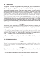
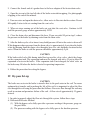
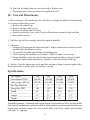
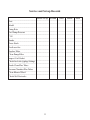
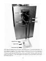
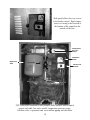
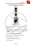
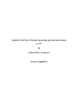
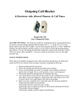
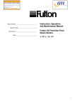
OTF
Oil Fired Pool
Heater
Installation
Operation
Maintenance
Manual
Service Policy
722010
Congratulations on the purchase of your new pool heater. In order to maintain peak performance of your pool heater it must be winterized at the end of the season, prior to the
onset of freezing weather. The burner and boiler must also be serviced annually. Servicing
of your appliance must be performed by a qualified technician. You should utilize a qualified heating and pool equipment technician familiar with your installation to manage your
heater and perform periodic maintenance. Proper care and maintenance of your pool heater
will allow you to enjoy the benefits of your pool heater as well as extend its useful life.
In the event that your serviceman encounters difficulty with the pool heater, they should
contact the distributor from which the product was purchased. The distributor will contact
the local manufacturer’s representative for assistance.
General Information
1. Read all instructions and review all diagrams prior to proceeding with installation.
2. Instructions and diagrams are intended only as guidelines. Installations must conform
with all applicable national, state and local codes. Additional guidelines are available from
National Fire Protection Association (NFPA), American Society of Mechanical Engineers
(ASME) and Building Officials, Code Administrators (BOCA), National Electric Code
(NEC), Uniform Mechanical Code (UMC) and Uniform Plumbing Code (UPC).
I. Installation Instructions
Message to the Installer.
Read these instructions completely before installation. Discuss the following CAUTION
NOTES with the person who will maintain the system after it is installed. Failure to follow
these instructions may result in damage to the equipment and void the warranty.
Take special care to note these important warnings.
1
CAUTION
An adjustable by-pass around the heat exchanger is required. The bypass is an important
and necessary component to obtain optimum performance. See the piping photograph and
instructions for adjusting the bypass.
CAUTION
The boiler section must be filled with fresh water, not chlorinated pool water. See filling
instructions.
CAUTION
The pool heater may not be used for salt water pools. Use of the pool heater in a salt water
pool will void the warranty.
CAUTION
The use of antifreeze in the boiler section is not recommended because it reduces heat transfer to the coil.
CAUTION
Winterizing: If the pool heater is installed in an area known to have freezing temperatures,
the boiler must be completely drained and the heat exchanger coil removed, drained and
stored in a warm place during periods of freezing temperatures. The heat exchanger coil is
not warranted for failure due to freezing.
CAUTION
The boiler must be placed on a level concrete floor or pad. Failure to level the boiler may
result in poor heat transfer due to air pockets in the boiler.
I. Locating the Heater
1. Before uncrating the unit, prepare the location for the boiler. It should be placed upon a
good level concrete floor or pad. Care should be taken to locate the unit for easy accessibility.
The pool heater should not be located near or under living spaces or windows. Maintain the
following clearances to combustible materials:
Front: 24 inches
Back: 24 inches
Sides: 12 inches
Windows: 3 feet
In addition, the air openings in the cabinet must have adequate clearance to allow for sufficient air intake to the burner. Un-crate the unit as close to its permanent location as possible
to prevent handling damage
2
II. Connections
1.Remove the front jacket panel and install the expansion tank which is shipped loose to
avoid damage during shipping. The vent cap, coil cover and pool piping instrument sensor
“T” also shipped loose. All other components are installed at the factory. See photograph
and diagram of piping for locations. Do not run any piping along the front access panel of
the heater as they may interfere with servicing. The tapings for connecting the unit to the
pool circulation lines are at the back of the heater. These connections are 1 ¼ inch npt. Connections should be made as per the piping photograph at the end of this manual. Copper
piping must be run from the coil inlet and outlet down to below the bottom of the coil flange.
The metal piping will act as a heat trap and reduce possible damage to the plastic pipes from
overheating. Install the 1 ¼”x1 ¼”x ¾ npt” Tee (PROVIDED) at the coil where the piping
from the pool filter/pump enters the coil. Install unions in the vertical piping as close to the
heat exchanger coil as possible but beyond the edges of the coil plate so they can be easily
removed for service and winterizing. Make the transition to plastic pipe on the other side
of the metal unions near to ground level.
CAUTION
An adjustable bypass around the heat exchanger is required. The bypass is important and
necessary to obtain optimum performance and protect the coil. See piping photograph at
the end of this manual.
2. The cable from the pool thermostat control is routed from the control inside the jacket
to the jacket opening for the coil. Remove the copper well from the end of the sensor cable.
Remove the sensor from the well. Apply pipe dope to the threads of the well and install it
in the “T”. Install the sensor in the well and connect the cable to the well.
3. Do not re-install the front jacket panel until the boiler is filled and the by-pass is adjusted.
III. Filling instructions
NOTE
The pool heater is an indirect heater using primary water in the boiler shell to act as a heat
transfer medium to the pool water flowing through a separate all copper and bronze heat
exchanger coil.
CAUTION
The pool heater, or boiler section, must be filled with fresh city water. Do not fill with
chlorinated water or water from the swimming pool.
1. Do not turn on electrical power to heater until boiler is properly filled with water.
3
2. Connect the female end of a garden hose to the hose adaptor of the heater drain valve.
3. Open the air vent at the top left side of the boiler recirculation piping. See photographs
of piping at the end of this manual.
4. Turn on water and open the drain valve, allow water to flow into boiler section. Do not
fill rapidly. Listen to the air venting from the vent valve.
5. When air stops coming out of the boiler air vent shut the vent valve. Continue to fill
until the pressure gauge reaches approximately 2 PSI.
6. Close the drain valve and disconnect the hose. If you exceeded 10 psi in step 5, reduce
the pressure in the boiler by draining water from the drain valve.
7. After the boiler cycles a few times it may build pressure till air in the water is driven off.
If this happens reduce pressure from the drain valve to approximately 8 psi when the boiler
is hot by draining from the drain valve through a hose to a safe discharge location for hot
water. When the boiler is cold the pressure should be approximately 2 psi.
CAUTION
If the boiler relief valve lifts during initial heat-up or after a few cycles, check the charge
on the expansion tank. The expansion tank must be charged with air to 12 psi to allow for
expansion of water in the boiler. If the expansion tank is not charged, the relief valve on
the boiler may lift when the boiler is heated to operating temperature.
8. Follow the procedure for setting the bypass.
IV. By-pass Set-up
CAUTION
The boiler uses water in the boiler to transfer heat to the pool water in the coil. To ensure
optimum heat transfer and to prolong the life of the coil it is important to adjust the flow
rate through the coil using the procedure that follows. Excessive flow through the coil may
result in erosion and premature failure of the coil. A flow rate of approximately 12 gpm is
desired.
1. In order to properly adjust the flow rate through the system, follow these steps:
A. Differential Pressure Method
(1). With the bypass valve fully open take a pressure reading at the pressure gauge on
the pool filter.
(2). The pressure reading with the bypass valve fully open is the baseline pressure.
4
(3). Slowly close the bypass valve so that the pressure increases.
(4). Stop when pressure reaches 2 to4 psi above the baseline at the filter. Mark the
position of the bypass for future reference.
B Differential Temperature Method
(1). Set the by-pass using the Differential Pressure Method noted above.
(2). Start the burner and wait until the boiler temperature is about 150 degrees F on the
pressure temperature gauge.
(3). Check the pool temperature and outlet temperature from the coil.
(4). Slowly close the bypass until the difference between pool temperature and outlet
temperature from the coil is between 14 and 20 degrees.
2. Pool temperature control should be set at the desired temperature.
3. Operate the burner in accordance with burner operating instructions.
V. Flue connection and Coil Cover:
1. The OTF heaters are provided with an outdoor vent cap to be installed directly on top of
the cabinet at the flue outlet. This vent cap provides for a waterproof unit as well as proper
control of combustion draft. The vent cap is shipped loose.
CAUTION
If the boiler is located in a pool house use standard flue piping to vent the flue gases outside
of the pool house.
2. A coil cover is also shipped loose and should be installed to protect the opening around
the coil from the weather.
VI. Winterizing The Heater:
If the pool heater is installed in an area known to have a freezing climate it is necessary to
completely drain both the primary boiler and remove, drain and store the heat exchanger
coil and gasket in a warm dry place. (The unions installed in the copper piping to and from
the coil will facilitate removal of the coil.) Connect a hose to the boiler drain at the bottom
of the boiler section. Open the vent valve at the top of the boiler, as well as the drain valve
and drain the boiler section completely.
Note: The heat exchanger coil is not warranted for failure due to freezing. Drain the coil
completely. Removing all of the water requires removal of the coil from the boiler and tilting
the coil back and forth until water in all of the sections of the coil is drained. Remove scale
from the exterior coil surfaces using a scale remover such as CLR. Store the coil in a warm
dry location during the winter months. Inspect the coil gasket for signs of cracking or wear.
Order a new gasket if necessary. Cover the opening of the coil in the heater with heavy duty
aluminum foil to prevent debris from falling into the boiler during the winter months.
5
VII. Spring Start-Up
Installing the heat exchanger coil:
Reinstall the heat exchanger coil after the last chance of freezing weather.
Note: The heat exchanger coil is not warranted for failure due to freezing.
Remove the foil covering the coil opening. Inspect the coil gasket and install a new gasket
if necessary. Carefully install the coil in the opening. Make sure that the nuts are tightened
evenly to avoid cocking the coil plate. Follow the filling instructions and start-up and operating instructions. Check that the heat exchanger coil nuts are tight before starting the burner
and again after the boiler is at operating temperature.
VIII. Start-Up and Operation
A. Start-up:
1. Make sure the electrical power is turned off.
2. Check the oil burner ignition electrodes carefully and adjust if necessary referring to the
oil burner manual instructions.
3. Check to be certain that the oil tank is full.
4. Be certain that the boiler is filled with water as per the filling instructions.
5. Check the pressure on the expansion tank is 12 psi.
CAUTION
The expansion tank must be charged with air to 12 psi to allow for expansion of water in
the boiler. If expansion tank is not charged , the relief valve on the boiler may lift when the
boiler is heated to operating temperature.
6. Turn on pool filter pump.
7. The limit control is factory set at 175° F and is not adjustable.
8. Start the oil burner in accordance with the burner manufacturers Operating Manual.
Allow the burner to operate continuously for at least 15 minutes. Then, using a combustion
analyzer adjust burner in accordance with burner manufacturer’s instructions. Draft readings
over the fire should be in the range from zero and negative 0.01. Final CO2 reading should
be approximately 10%.
6
9. The recirculation loop located on the heat exchanger above the burner re-circulates water
from the bottom of the boiler to the top whenever there is power to the boiler. Re-circulation
enhances heat exchange efficiency. An automatic vent valve located in the top left section
of the piping automatically vents gases from the system if they come out of solution.
Trouble Shooting
1. Motor does not run.
a. Check fuses and power to heater.
b. Set pool temperature control and boiler temperature limit to highest setting.
c. Reset primary control. Push red button. Reset button should only be pushed one time!
d. Check for defective temperature controls by jumping the controls one side at a time.
e. Check for power to motor.
f. Ensure that boiler is filled and pressurized with water. (The low water cutoff will
interrupt the electrical circuit to the burner if the boiler water level is low.)
2. Motor runs -no fire.
a. No oil in tank.
b. Dead or plugged burner nozzle.
c. Blocked oil line.
d. Loose transformer connections or defective ignition transformer.
e. Inspect electrode settings and insulators.
f. Check fuel pump pressure.
3. Burner fires shuts down
a. Defective cad cell.
b. Dirty cad cell.
c. Defective primary control
d. Improper burner adjustment.
4. Smoke coming out of flue
a. Clogged nozzle.
b. Dirty fan or air handling parts.
c. Improper burner adjustment.
5. Cycling on or off:
a. Differential between pool setting and high limit too close.
b. Remote pool sensing bulb in outlet water piping instead of inlet water piping.
c. Bypass not adjusted properly. Follow bypass adjustment procedure.
6. Boiler relief valve lifts.
a. Expansion tank is not charged. Cool boiler to ambient temperature, re-charge
expansion tank to 12 psi and follow filling procedure.
7
b. Pool coil is leaking domestic water into boiler. Replace coil.
c. Pool temperature sensor not inserted completely in well.
IX. Care and Maintenance
1. Heat exchanger: The tubular portions of the heat exchanger should be cleaned annually
or at startup each heating season.
a. Remove the cabinet top.
b. Remove the flue collector top.
c. Remove all baffles from fire tubes.
d. Brush clean the flue ways with a 2 inch soft brush and vacuum the unit carefully.
e. Reassemble the unit.
2. Oil filter: the oil filter cartridge should be replaced annually.
3. Oil burner:
a. Thoroughly brush clean the burner fan blades. Proper combustion air delivery is only
possible when fan blades are clean.
b. Clean nozzle assembly and all other air handling parts.
c. Check spacing and condition of electrodes. Adjust or replace as necessary.
d. Nozzle should be replaced if nozzle does not perform according to the prescribed
conditions under burner adjustments. Replace it with only the specified type.
4. Gaskets: Carefully tighten nuts on the pool heat exchanger flange to prevent gasket leaks.
Deterioration due to gasket leaks will void the warranty.
Specifications
OTF Model
510
801
1010
1600
______________________________________________________________________________
Gross Input BTU/hr
140,000
210,000
280,000
350,000
______________________________________________________________________________
Gross Output BTU/hr
109,200
163,800
218,400
273,000
______________________________________________________________________________
Flue Pipe Diameter
6”
6”
8”
8”
______________________________________________________________________________
Firing Rate GPH
1.00
1.50
2.00
2.50
______________________________________________________________________________
Width
22”
22”
26 ¼”
26 ¼”
______________________________________________________________________________
Length
31”
31”
34”
34”
______________________________________________________________________________
Height
38 ½”
38 ½”
45”
45”
Standard Equipment: Aluminum jacket with integral vent cap and coil cover, dry base boiler
with cement combustion chamber installed or wet leg boiler, expansion tank, theraltimeter,
burner, pool and limit control, low water cutoff, boiler relief valve, indirect pool heating
coil with 1 ¼” tappings.
8
Homeowner Information
WARNING
Even though the vent cap is 40 inches above the ground, keep small children away from
your pool heater.
Record the boiler serial number for future reference:____________________________
Boiler installed by:
Name__________________________________________________________________
Address: _______________________________________________________________
______________________________________________________________________
______________________________________________________________________
Phone:_________________________________________________________________
For Boiler Service Contact:
Name__________________________________________________________________
Address: _________________________________________________________________
______________________________________________________________________
______________________________________________________________________
Phone:_________________________________________________________________
Service Information: To avoid unnecessary expense and inconvenience your pool heater
must be winterized prior to freezing weather and cleaned and serviced annually by a qualified service technician. If any problems occur check the following before calling a service
technician.
1. Check to be sure there is fuel in the tank and if there is a fuel shutoff valve it is open.
2. Make sure the power switch is turned on.
3. Check to see if the desired pool temperature setting is greater than the current temperature
of the pool.
9
Swimming Pool Heater Warranty
The heat exchanger of the Swimming Pool Heater is warranted against defects in material and workmanship for a period of 5 years from the date of installation. The indirect heat exchanger coil (Copper pool coil) is guaranteed for 1 year against defects
in material and workmanship from the date of installation. All other components are
guaranteed to the extent of the manufacturer’s warranty. This warranty does not cover:
1. Components of the system supplied by others.
2. Workmanship of the installer. This warranty does not assume any liability of any
nature for unsatisfactory performance caused by improper installation.
3. Shipping damage. Any evidence of shipping damage must be reported to the
shipping company immediately and a claim filed. Do not install the boiler.
4. Improper adjustment, control settings, care, maintenance or failure to follow
installation instructions provided with the boiler.
5. Defects resulting from freezing, excessive pressure, temperature or leaks at water
connections or any similar cause.
6. Any installation that has been modified, neglected, altered, tampered with,
vandalized, misused subjected to accident, fire, flood or other casualty.
7. Damage due to deterioration and failure to maintain the boiler.
8. In and out charges.
9. Labor.
This warranty extends only to the first purchaser at retail and only when the boiler is
in the original installation site, which must be within the continental limits of the
United States of America.
Implied warranties of fitness for a particular purpose and merchantability shall be
limited to the duration of the express warranty. Manufacturer expressly disclaims and
excludes any liability for consequential or incidental damages for breach of an express
or implied warranty, except as otherwise provided by state law.
This warranty gives you specific legal rights. You may have other rights that vary
from state to state.
10
Service and Set-up Records
Initial Set-up Second Third
Fourth
Fifth
___________________________________________________________________________________
Date
___________________________________________________________________________________
Model
___________________________________________________________________________________
Firing Rate
___________________________________________________________________________________
Fuel Pump Pressure
___________________________________________________________________________________
CO2
___________________________________________________________________________________
Smoke
___________________________________________________________________________________
Gross Stack
___________________________________________________________________________________
Draft over fire
___________________________________________________________________________________
Replace Filter
___________________________________________________________________________________
Clean Pump Filter
___________________________________________________________________________________
Inspect Coil Gasket
___________________________________________________________________________________
Check for leaks @plugs/fittings
___________________________________________________________________________________
Brush Clean Flue Tubes
___________________________________________________________________________________
Vacuum Chamber/Flue Tubes
___________________________________________________________________________________
Clean Blower Wheel
___________________________________________________________________________________
Check/Set Electrodes
11
Coil Plate
Union
Sensor
Fitting
Sensor
Cable
Union
Supply To Pool
Bypass Valve
Return From Pool
OTF Suggested piping from coil to pool. Instrument sensor “T” provided with boiler. All
other piping not supplied. Note copper piping to and from coil to act as a heat sink transitions to PVC with full flow bypass valve. Sensor “T” location is noted. Unions will allow
easy disassembly and removal of coil prior to freezing weather. Note that pool water to the
coil is to the sensor “T” side of the piping in the top of the coil and return to pool is from
the bottom of the coil.
12
Slide panel allows for easy access
to the boiler control. Pool temperature is set using a dial located at
the bottom of the control on the
outside of the box.
Temperature
Pressure
Gauge
Low Water
Cutoff
Expansion
Tank
Circulator
Thermostat
Control
Drain Valve
OTF with jacket removed to show burner, boiler control, boiler control
sensor and cable, low water cutoff, temperature pressure gauge,
fill/drain valve, expansion tank, recirculation piping and circulator.
13
MET-7444