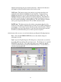
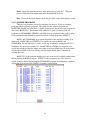
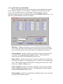
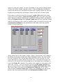
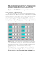
1
Sonata/Sonata XT ® Peptide Synthesizer USER MANUAL ® © 2010, Protein Technologies, Inc. 4675 S. Coach Dr. Tucson, AZ 85714 USA All Rights Reserved Document #9030010 Rev 04 Front Cover: Certain features shown on Sonata® XT not provided with Sonata®. WARNING TIMES. A REACTION VESSEL MUST BE IN PLACE AT ALL WARNING DO NOT ATTEMPT TO MOVE THE SONATA WHILE ANY OF THE SOLVENT OR WASTE CONTAINERS CONTAIN LIQUIDS. WARNING THE SOLVENT CABINET CONTAINS HAZARDOUS CHEMICALS THAT ARE UNDER PRESSURE DURING NORMAL OPERATION PLEASE REFER TO SECTION 7.2 OF THIS MANUAL FOR M.S.D.S. INFORMATION AND PLEASE FOLLOW ALL SAFETY RECOMMENDATIONS. TABLE OF CONTENTS SECTION 1 INTRODUCTION AND SYSTEM DESCRIPTION 1.1 1.2 1.3 Introduction ………………………………………….………………. …… 1 System Description 1.2.1 Pneumatic Pump…………………………….……………………... 2 1.2.2 Nitrogen Supply…………………………………..………..………. 2 1.2.3 Valve System………………………………………….…………….3 1.2.4 Fluid Metering…………………………………………...………… 3 1.2.5 Amino Acid Reservoir System…………………………..………. 3 1.2.6 Solvent Supply System…………………………………...……… 4 1.2.7 Waste System………………………………………….…………… 6 1.2.8 Collection System…………………………………………..……….7 1.2.9 Reaction Vessel System……………………………………………. 7 1.2.10 Pneumatic Inlet System……………….…………...……….………. 7 Pneumatic Failures……………………….…..…………….. 9 1.2.11 Fluid Sensors……………………………………………….………. 9 1.2.12 Computer Enclosures………………………………………………. 9 1.2.13 PC Computer……………………………………………….……….9 1.2.13.1 Connecting to a Network………………………………… 10 1.2.13.2 Loading other software…….…………………………….. 10 1.2.13.3 Printer………….………….….……………….…………. 10 System Connections 1.3.1 Electrical Connections……………………………...……………… 11 1.3.2 Nitrogen Supply…………………………………………….……… 11 1.3.3 Vent………………………………………………………………… 11 SECTION 2 SONATA® OPERATIONS 2.1 PC Software 2.1.1 Edit Synthesis………………………………………….…………… 12 2.1.1.1 Synthesis Editor……………………………………………. 12 2.1.2 Edit Program……………………………………………..………… 17 2.1.2.1 Program Editor…………………………………………….. 17 Step………………………………………………………… 17 Solvent, Action…………………………………………….. 18 Fill Type, Fill Time……………..………………….……… 21 Op-Time, Op-Type………………………………………… 22 2.1.2.2 Sample Programs……………………………………………25 2.1.3 Synthesis Setup…………………………………………………….. 26 Reagent Excess…………………………………………….. 26 Synthesis Scale, Resin Substitution……………...………… 27 Resin Needed, Volume 1, Volume 2, RV Size…………….. 27 i 2.1.4 2.1.5 2.1.6 2.1.7 2.1.8 2.1.9 2.1.10 2.1.11 2.1.12 Print List…………………………………………………… 28 2.1.3.1 Calculate…………………………………………………… 29 Synthesis Sequence/AA Calculations……………………… 29 2.1.3.2 Solvent Calculation………………………………………… 31 2.1.3.2.1 Solvent Cost……………………………….. 32 2.1.3.3 Amino Acid Cost…………………………………...……… 33 2.1.3.4 Activant Calculations………………………………………. 35 2.1.3.5 Amino Acid Molarity Calculation………………………….. 36 2.1.3.6 Setup Machine …………………………………………….. 39 2.1.3.6.1 AA Machine Setup…………………………. 39 Manual Operations…………………………………………………. 41 Individual, Step Mode and Operation……………………… 41 Fill Time/Fill Type, Solvent, Op-Time, Drain………...…… 42 Rep. (repetitions), Mix Mode……………………………… 43 Solvent Preparation………………………………………………… 43 AA Prep (Amino Acid Preparation)……………………………….. 45 View Report File…………………………………………………… 47 Report List…………………………………………………. 47 Global Configure………………………………………...………… 48 Global Machine Configuration…………………………….. 48 Calculator………………………………………………………….. 50 Data………………………………………………………………… 51 2.1.10.1 Reagent Data…………………………………………….. 51 Standard AA Reagent Data………………………………. 51 2.1.10.1.1 Optional AA Reagent Data………………… 53 2.1.10.1.2 Activant Reagent Data…………………….. 54 2.1.10.2 Solvent Data……………………………………………… 56 2.1.10.2.1 Standard Solvent Bottle Data……………… 56 2.1.10.2.2 Alternate Solvents………………………….. 58 2.1.10.3 Calculate Yield………………………………..………… 59 2.1.10.4 Calculate Time…………………………………………….60 Setup……………………………………………………………….. 62 2.1.11.1 Sonata Operation Times…………………………………. 62 2.1.11.2 Waste Setup……………………………………………… 65 Tools………………………………………………………………. 66 2.1.12.1 Valve Map……………………………………………….. 66 2.1.12.2 Diagnostics………………………………………………. 67 Speed Check………………………………………………67 2.1.12.3 Cleaning………………………………………………….. 68 Cleaning Solvent Select Screen………………………….. 68 System/Subsystem Cleaning…………………..………… 68 2.1.12.4 File Maintenance…………………………………………. 72 File Delete Utility Screen………………………………… 72 2.1.12.5 Password…………………………………………………. 73 Change Password………………………………………… 73 ii 2.2 SECTION 3 3.1 3.2 3.3 SECTION 4 4.1 4.2 4.3 4.4 4.5 4.6 4.7 4.8 4.9 4.10 Lock/Unlock System…………………………………….. 74 2.1.12.6 New Feature in Program and Synthesis Editor Screens…. ………………………………74 2.1.13 Set Pause or Go To………………………………………………… 74 GOTO Step-Pause Flags…………………………………. 74 Scroll Peptide, Scroll Program…………………………… 75 Scroll Program…………………………………………….75 Instrument Software (EPROM)……………………………………………. 76 ERRORS AND RECOVERY Critical Errors – No Operations Allowed………………………………….. 77 Messages and/or Operational Errors……………………………………….. 79 Restore Feature…………………………………………………………….. 82 CLEANING AND MAINTENANCE Post Synthesis Cleaning……………………………………………………. 83 4.1.1 Reaction Vessel and Lines…………………………………………. 83 4.1.2 Collect Line………………………………………………………… 83 4.1.3 Amino Acid Lines………………………………………………….. 84 4.1.4 Solvent Lines and Volumetric Flasks………………..……………. 84 Cleaning Entire System…………………………………………………….. 85 4.2.1 Clean Entire System……………………………………………….. 85 Routine/Preventive Maintenance……………………………..…………… 85 4.3.1 N2 Leak Check…………………………………………………….. 85 4.3.2 Solvent/AA Bottle Filter Replacement…………………………….. 86 4.3.3 AA Lines Clean or Clean Entire System……………..…………… 87 4.3.4 Fan Filter Cleaning……………………………………..…………. 87 Cabinet Cleaning…………………………………………………………… 87 Solvent Bottle Seal Replacement………………………………………….. 87 AA Bottle Seal Replacement………………………………………………. 88 Buss Speed Calibration…………………………………………………….. 88 Annual Maintenance……………………………………………………….. 89 4.8.1 Replace Solvent Bottles Fluid Plate Valves……………………….. 89 4.8.2 Replace Solvent Bottle Supply Fittings……………………………. 89 4.8.3 Replace Pneumatic Pump Filters……………………..…………… 89 Shut Down Procedures…………………………………………………….. 89 4.9.1 1 to 3 Days Before Next Synthesis………………………………… 89 4.9.2 3 to 20 Days Before Next Synthesis or Pneumatic Pump Shut Down………………………………………. 90 4.9.3 Long Term Shut Down…………………………………………….. 90 Solvent 1 and Recirculation Pump Maintenance…………………..……… 90 4.10.1 Equipment and Tools………………………………………………. 90 4.10.2 Pump Tube Replacement………………………………………….. 90 iii 4.10.3 Solvent 1 Tubing Adjustment……………………………………… 91 4.10.4 Recirculate Pump Tubing Adjustment…………………………….. 91 SECTION 5 5.1 SECTION 6 6.1 6.2 SECTION 7 7.1 7.2 SECTION 8 8.1 8.2 8.3 8.4 8.5 8.6 8.7 8.8 8.9 8.10 8.11 8.12 8.13 8.14 8.15 TROUBLE SHOOTING Nitrogen Leak Test………………………………………………………… 93 Check for N2 Leaks ……………………………………………….. 93 Regulator and QC Test…………………………………………….. 93 Internal N2 System Test…………………………………………… 93 Solvent System Test……………………………………………….. 94 INSTALLATION PC Software Installation from 3.5" Disk…………………………..……… 95 Instrument Installation Procedure………………………………………….. 95 HANDLING AND SHELF LIFE OF REAGENTS Reagent Shelf Life………………………………………………..……….. 97 7.1.1 AA Degradation Test……………………………………………… 98 MSDS Sheets 7.2.1 N,N-Dimethylformamide…………………………………...……… 99 7.2.2 Piperidine……………………………………………………………102 7.2.3 Acetic Anhydride…………………………………………..……… 105 7.2.4 4-Methylmorpholine………………………………………..……... 108 7.2.5 Triflouroacetic Acid………………………………………………... 111 7.2.6 Methylene Chloride………………………………………..……… 114 DATA ACQUISITION OPTION Data Acquisition Button…………………………………………………… 117 Data Acquisition Logic…………………………………………………….. 117 Recirculate Data Rate Adjustment Box……………………………………. 117 Delay After Sensor Adjustment…………………………………………… 117 Acquisition Pause Adjustment…………………………………………….. 118 IF – Input Type and Input Value…………………………………………… 118 THEN – Output Type and Output Value…………………………………... 119 ELSE - Output Type and Output Value…………………………………… 119 Offset Channel Adjustment…………………………………..…………… 119 Max Unit Adjustment……………………………………………………… 120 Max Volt Input Adjustment……………………………………………….. 120 Unit Type Select…………………………………………..………………. 120 Load……………………………………………………………………….. 120 Save………………………………………………………………………… 120 Print………………………………………………………………………… 120 iv 8.16 8.17 SECTION 9 9.1 9.2 9.3 9.4 9.5 SECTION 10 10.1 SECTION 11 11.1 Progress……………………………………………………………………. 121 Exit…………………………………………………………………………. 121 PROGRAM EDITOR SCREEN Action List – Options for Data Acquisition……………………………….. 122 RV Bottom Data Pause…………………………………………………….. 122 Acquire Data……………………………………………………………….. 122 Mixing W/Data Acquisition (Rec.-Data, Rec/Ag-Data)…………………… 122 Drain/Pause………………………………………………………………… 122 DIAGNOSTICS SCREEN Set DAC Button…………………………………………………………… 124 SONATA® OPERATION TIMES SCREEN New Feature in Operation Times Screen………………………………….. 125 Appendices: (6) Sample Programs Pneumatic Schematic Drawing Fluid Schematic Drawing v 1 INTRODUCTION AND SYSTEM DESCRIPTION 1.1 INTRODUCTION The SONATA® / SONATA® XT bio-organic synthesizer is an instrument specifically designed for automated solid phase synthesis with a multitude of solvents. The unparalleled design supports FMOC, t-Boc, and combinatorial chemistry to produce milligrams to grams of desired product. The SONATA® has chemically inert, optimized channels allowing high solution transfer rates (>300 ml/min) of any solvent. All reactions occur in an inert environment to minimize undesirable side reactions. Multiple mixing modes including nitrogen bubbling, recirculation and mechanical agitation can be combined to maximize reaction efficiency. Fluid-filling methods can be selected for optimal performance. The unit was designed to contain all solvents, pumps, and waste in one cabinet. The solvent cabinet holds up to seven different solvent/reagents as well as two 20-liter waste containers. The ventilation for the entire system is a 4" (10cm) vent to be connected to the lab ventilation system. The (20) 300ml amino acid reservoirs are located in the upper cabinet besides the reaction vessel compartment. The electronic compartment is physically isolated from the valve compartment and the upper cabinet is vented to the solvent cabinet. Controlled by a stand alone PC, and with a versatile, easy-to-use point-and-click Windows-based software, it allows the experienced chemist or novice operator complete control of all aspects of a synthesis. The software is powerful, fast, flexible, and easy to learn. Context sensitive online help is available. Editing and data calculations can be performed while the synthesis proceeds. The software generates a complete record documenting each step of the synthesis. The SONATA® is covered by a one-year warranty. Extended warranty contracts are available through Technical Service. 1 1.2. SYSTEM DESCRIPTION 1.2.1 PNEUMATIC PUMP The matrix valve system requires 80 - 90 psig air pressure for proper operation. The pneumatic pump located at the rear of the solvent cabinet provides both 90 psig air pressure and 24" of vacuum to the instrument. The pump is designed for continuous operation in harsh environments. The high-pressure air is regulated at the pump by a pressure relief valve, which bleeds off the excess air not required by the unit. The air passes through a filter/moisture trap with an automatic drain before exiting the rear of the instrument. CAUTION - THE PUMP CANNOT START IF THERE IS PRESSURE IN THE SUPPLY LINE. REMOVE THE AIR, QUICK DISCONNECT AND PRESS ON THE TIP TO RELEASE RESIDUAL PRESSURE. ATTEMPTING TO START WITH PRESSURE WILL CAUSE THE FUSE TO BLOW! NOTE - IF DESIRED, THE UNIT CAN BE CONNECTED TO HOUSE AIR AND VACUUM TO ELIMINATE THE PNEUMATIC PUMP. IT IS IMPERATIVE THAT THEY BE RELIABLE SINCE EVEN MOMENTARY LAPSES IN SUPPLY WILL CAUSE THE INSTRUMENT TO STOP OPERATIONS. 1.2.2 NITROGEN SUPPLY A relatively pure (>99.9%) and dry source of pressurized nitrogen is recommended since it will be the used for the reagents. The system uses the nitrogen for solution transfers and agitation. To maximize operating time and minimize down time two nitrogen tanks can be connected to the unit via the quick connects on the side of the unit. The two nitrogen quick connect fittings are connected to a shuttle valve which selects the supply with the highest pressure. IMPORTANT - SECURELY FASTEN THE CYLINDERS WITH SAFETY STRAPS TO PREVENT THEM FROM FALLING! HINT - BY SETTING THE N2 TANK REGULATORS 5 PSIG (35 kPa) APART, I.E., 75 (500 kPa) AND 80 PSIG (550 kPa), THE 80 PSIG TANK WILL BE EXHAUSTED BEFORE THE VALVE WILL SWITCH TO THE 75 PSIG TANK. WHEN YOU REPLACE THE EMPTY TANK, SIMPLY TURN THE PRESSURE SETTING OF THE 75 PSIG TANK UP TO 80 PSIG, AND THE NEW TANK DOWN TO 75 PSIG. THIS ALLOWS EFFICIENT ROTATION OF THE TANKS. 2 The high pressure setting on the regulators is required in the event the pneumatic pump fails. If this happens, the unit automatically switches to nitrogen for sealing the matrix valves. The N2 pressure regulators and distribution system is the pneumatic inlet system (Sec. 1.2.10). The nitrogen tubing and quick connect fittings are provided with the unit. The tubing has 1/4" male NPT fittings to adapt to the regulators and tanks that must be provided by the user. 1.2.3 VALVE SYSTEM The valve system is the key component in the SONATA® It is a manifold of pneumatically operated membrane valves constructed of chemically resistant materials, Techtron (polyphenylene sulfide) and FEP (flouro-elastomer polymer). The valve system is a unique arrangement of membrane valves which provide common solution supply ports to the reaction vessel. Actuation of the membrane valves is achieved by the highly reliable electromechanical pilot valves, situated above the membrane valves. The pilot valves are rated at millions of operations, have indicating LED's and a mechanical bypass, and are easily field replaceable to facilitate service. Protein Technologies, Inc. purposely designed the FEP valve membranes to be field replaceable; the lab need not buy a new valve should a membrane need to be replaced. 1.2.4 FLUID METERING The solution measurement in the SONATA® can be accomplished by either of three methods. By using the two interchangeable precision volume vessels (with a ± 2%), filling by time (±5%), or fill to the top of the reaction vessel. The operator specifies the number of volume aliquots of each solvent and reagent delivered to the reaction vessel depending on the scale of each synthesis. The metering loop design is not subject to differences in fluid viscosity or mechanical failure inherent in other designs. 1.2.5 AMINO ACID RESERVOIR SYSTEM The 20 amino acid reservoirs are located on the front of the SONATA cabinet. The reservoirs have 300 mL capacities and can be connected quickly and positively with a unique quick-disconnect system. A slide locks the reservoir in place, and a safety gate inhibits the operator from removing a reservoir that is pressurized. The control of the amino acid reservoirs is accomplished in Reagent Data, under the Data drop down box, and in the Amino Acid Preparation screen. IMPORTANT - ALL 20 AMINO ACID POSITIONS MUST HAVE BOTTLES TO PRESSURIZE. PLACE EMPTY BOTTLES IN ANY POSITION THAT IS NOT REQUIRED. FLUSHING OPERATIONS CAN BE PERFORMED ON INDIVIDUAL POSITIONS IN THE AMINO ACID PREP. SCREEN. Each AA reservoir has a bottle filter to prevent particulate from entering the matrix valve block. These filters should be changed on a regular basis; the frequency would be dependent upon the quality and concentration of reagent utilized. See Section 4.3.2 (Bottle Filter Replacement) for instructions. 3 To install or remove AA reservoirs, the safety gate must be manually lifted to allow movement of the metal slides. An electronic micro-switch monitors the physical position of the safety gate. If the gate is unable to close, an error message will appear with instructions and the AA fluid system will not operate properly. To install a reservoir, just lift the safety gates to open. Insert the bottle filter and Teflon line into the bottleneck, pull the metal slide out and push the amino acid bottle upward into position. Push the metal slide back in to lock the bottle in place. Check that the bottle filter is resting against the lower rear corner of the bottle. This will ensure that all of the reagent in the bottle will be used. IMPORTANT - THE AA MANIFOLD SEALS ARE MADE OF SILICONE FOR RELIABILITY AND EASE OF SEALING. THE SEALS ARE NOT AFFECTED BY DMF (DIMETHYLFORMAMIDE) OR NMP (N-METHYLPYROLIDONE). RECENT STUDIES HAVE SHOWN THAT THF (TETRAHYDROFURAN) AND DCM (METHYLENE CHLORIDE) CAN BE UTILIZED WITHOUT DESTRUCTION OF THE SEALS IF EXTRA CAUTION IS USED TO PREVENT THE LIQUID FROM CONTACTING THE SEALS. CONTACT TECHNICAL SERVICE IF ALTERNATIVE SOLVENTS ARE DESIRED. UNDER NO CIRCUMSTANCES SHOULD TFA (TRIFLOUROACETIC ACID) BE USED IN THE AA MANIFOLD SYSTEM, DESTRUCTION OF THE SEALS AND PNEUMATIC QUICK-DISCONNECT SYSTEM WILL OCCUR! THIS ACTION WILL VOID YOUR GUARANTEE! SEE SECTION 4.10 AA SEAL REPLACEMENT FOR REPLACEMENT PROCEDURES. SONATA XT: The 20 amino acid reservoirs are located on the right of the SONATA cabinet. The reservoirs have 500 mL or 1 L capacities and can be connected quickly and easily. The control of the amino acid reservoirs is accomplished in Reagent Data, under the Data drop down box, and in the Amino Acid Preparation screen. Each AA reservoir has a bottle filter to prevent particulate from entering the matrix valve block. These filters should be changed on a regular basis; the frequency would be dependent upon the quality and concentration of reagent utilized. See Section 4.3.2 (Bottle Filter Replacement) for instructions. To install a reservoir, insert the bottle filter and Teflon line into the bottleneck, and tighten down the cap. Check that the bottle filter is resting against the lowest part of the bottle. This will ensure that all of the reagent in the bottle will be used. 1.2.6 SOLVENT SUPPLY SYSTEM The seven solvent and reagent bottles are located in the solvent cabinet. The fluid in the solvent 1 position moved through pumping action. The other six bottles are pressurized with nitrogen (argon) to accomplish solution transfer. The control of the solvent supply bottles is accomplished in the SOLVENT PREPARATION screen. 4 The seven solution bottle positions include the primary and secondary solvents. Throughout the SONATA® software program, each bottle position is referred to by an abbreviated title. The titles and bottle volumes of each bottle position are as follows: STANDARD SOLVENT BOTTLE VOLUME CONFIGURATION SOLV1: This solvent bottle position is the only position not pressurized. The standard volume is 1 to 20-liter supply. (options are available capable of handling 1 to 200 L supply). The SOLV 1 position is for the primary wash solvent, typically reagent grade N,N-dimethylformamide (DMF). Dimethylacetamide (DMA) or N-methylpyrrolidone (NMP) may also be used. Because this solvent is quite stable, the 20 L container may be installed and left in place throughout several sets of syntheses. This solvent is utilized in the automated clearing and cleaning operations for the valve blocks, therefore SOLV1 must be in place and primed for normal operation of the instrument. SOLV 2 to SOLV 7: Bottle positions consist of N2 pressurized 1 - 4 L bottles. For standard peptide synthesis, the SOLV 2 position can be used as the deprotectant bottle position. The deprotectant is used to remove the N-terminal FMOC protecting group. The standard composition is 20% (v/v) piperidine in DMF. This solution is also quite stable and may be installed and used for several sets of syntheses. This solvent position is also utilized for intensive cleaning routines, RVCLN,AA LINE CLEAN, AA SYSTEM CLEAN. SOLV 3: Bottle position can be used as the activating solution to form the activated FMOC amino acid for the coupling reaction. The standard composition is 100 or 200 mM HBTU/0.4 M 4-Methylmorpholine in DMF. NOTE: The activator solution must be equimolar with the amino acid solutions. The activator solution should be prepared fresh for each syntheses. SOLV 4: Bottle position can be used for the capping solution to permanently block any unreacted amino groups following a coupling reaction or to acetylate the Nterminus of a completed peptide. Acetic anhydride may be used. Other reagents may be loaded for alternate chemistries. SOLV 5: Bottle position can be used in standard peptide synthesis for the secondary solvent, such as methylene chloride (DCM) to wash the peptide-resin in preparation for automated cleavage. DCM may be installed and left in place indefinitely. SOLV 6: Bottle position can be used in standard peptide synthesis for the cleavage reagent for cleavage of the peptide from the resin after synthesis is complete. The TFA solution should contain the appropriate scavengers depending on the protecting groups attached to the amino acids. Due to the aggressive nature of TFA, it is recommended to VENT and FLUSH N2 on the cleave position when not is use. The scavengers in the standard composition should be prepared fresh for each syntheses. 5 Each solvent position has a bottle filter to prevent particulate from entering the valve system. For replacement procedures, see Section 4.3.2. A Teflon encapsulated O-ring in a Teflon insert establishes the bottle seals and is inert to the reagents. Damage to the insert or O-rings will result in N2 leakage and potential loss of reagent (volatiles like TFA, DCM). For bottle seal replacement procedures, see Section 4.9. CAUTION - PRIOR TO INSTALLING OR REMOVING SOLVENT BOTTLES, MAKE SURE THE SOLVENT CABINET SLIDING SHELF IS IN TO PREVENT INJURY. To install a solvent bottle, first verify that the solution line has a bottle filter and that the O-ring is properly installed in the bottle insert. Dress the line so that it is straight to go to the bottom of the bottle (FEP tubing can be 'molded' by gentle bending, do not 'kink' or the tubing integrity will be compromised). Attach the cap and tighten to a firm hand tight. Each solvent position has a fluid sensor to detect the presence or absence of fluid. The seven solvent fluid sensors are located in the SONATA® cabinet next to the pneumatic inlet assembly. Alternative bottle sizes and configurations are available. Custom configurations can be arranged through technical service. 1.2.7 WASTE SYSTEM The SONATA® utilizes two 20-liter waste containers for storage of all wastes from the instrument. The only exit for the closed flow paths of the instrument is through the waste system. Each container is fitted with a solution level switch to prevent overfilling. When one of the containers is full, the waste is diverted to the other container and a 'WASTE 1 FULL' message will appear on the bottom left corner of the main menu screen. If both containers are full, all operations in the instrument will stop automatically. A 'WASTE 1 & 2 FULL' message will appear on the display and in the progress files of the synthesis that was in progress. No operations will be allowed until at least one container is emptied and reconnected. IMPORTANT - BOTH WASTE CONTAINERS BEING FULL IS A CRITICAL ERROR ON THE SONATA®. TO PREVENT OVERFILLING, THE INSTRUMENT WILL AUTOMATICALLY PAUSE ALL OPERATIONS AND VENT ALL SUPPLY BOTTLES, AA'S AND SOLV'S. TO RESUME OPERATIONS, FIRST EMPTY AND RECONNECT A CONTAINER, THEN PRESSURIZE THE SUPPLY BOTTLES. GO TO MAIN SCREEN AND PRESS GO TO RESUME OPERATIONS. The waste container level switches are wired in a normally closed (NC) configuration so if the switch is disconnected, it is the same as if the container is full. This logic prevents waste being delivered to a disconnected container. The connectors are made of peek and gold plated contacts for resistance to the aggressive waste solutions. 6 Do not attempt to disassemble the switch connector assembly. It is not a field service item and damage will occur. HINT - WASTE TANK #1 IS THE NORMAL OPEN (DEFAULT) POSITION FOR THE WASTE SWITCHING VALVE AND THEREFORE IS THE PREFERRED POSITION FOR WASTES. USING WASTE #1 AS THE STANDARD WASTE POSITION WILL MINIMIZE THE 'OPERATING HOURS' PUT ON THE WASTE VALVE AND EXTEND THE LIFETIME OF THE VALVE. HINT - DUE TO THE AGGRESSIVE NATURE OF CLEAVAGE REAGENTS, IT IS RECOMMENDED TO VENT AND FLUSH N2 TO THE CLEAVE REAGENT WHEN NOT IMMEDIATELY REQUIRED. 1.2.8 COLLECTION SYSTEM The collection system in the SONATA® consists of directing the fluid from the reaction vessel to the collection port by pushing N2 from the RV top. Sensor logic is employed to verify the correct transfer of the fluid to the collection port. An optional capability is the output of a 'trigger' to inform a fraction collection system to advance position upon completion of the step. Contact Technical Service for details on usage of this optional feature. The collection tubing is not capable of being rinsed automatically since it exits into the collection tube, flask or vessel. Therefore, it is important that after a collection operation occurs, a cleaning process be performed. The cleaning operation is denoted as a Collect Line Subsystem Cleaning and can be performed from the Tools, Cleaning screen in the main menu. See Section (2.1.12.3-D), for detailed information on the collection tube rinse process. 1.2.9 REACTION VESSEL SYSTEM The SONATA® reaction vessel system is designed around a simple reliable quick release mechanism. The reaction vessel is connected to 3/16" FEP Teflon tubing with TFE Teflon fittings. A UHMW polyethylene RV holder and drip tray houses the RV enclosure to contain small quantities of liquid. The RV enclosure is design to accommodate a variety of RV sizes. The standard sizes are 200 mL, 500 mL, 1.2 L, 2 L, 3.2 L and 4.2 L. 1.2.10 PNEUMATIC INLET SYSTEM The pneumatic inlet is the primary control assembly for the air, vacuum and N2. The inlet status of each supply is monitored by pneumatic switches. The lack of any one of these supplies is a critical error and causes all operations to pause. A message will appear stating the problem source and will be written to all progress files of the synthesis 7 that is in progress. No operations will be allowed until the supply is restored. See the end of this section for specific failures and instrument responses. REFER TO PNEUMATIC SCHEMATIC FIGURES ATTACHED TO END OF MANUAL FOR CLARIFICATION The nitrogen supply switch acuates at 60 - 69 psig, therefore, a minimum of 70 psig must be supplied for the instrument to operate. The supply pressure is reduced by the N2 regulator to 10-12 psig. This N2 is fed into a custom check valve manifold to both divert the N2 as well as prevent any back flow or cross talk between AA and SOLV supplies. The check valve assembly is constructed of UHMW Polyethylene with ZALAK O-rings and Techtron PPS to be inert to all reagents, even TFA. The N2 then goes to Teflon valves to control pressurization and venting of the various supplies. These valves are normally open to vent so the default status for the bottles is vented. IMPORTANT - POWER LOSS, EVEN MOMENTARILY, WILL CAUSE THE BOTTLE PRESSURIZATION VALVES TO VENT THEIR RESPECTIVE PRESSURES. The low pressure N2 is also diverted to the N2 bubbling/mixing rate in the reaction vessel. This low pressure N2 flow controls the N2 used for the dispose (drain) operation in the reaction vessel. IMPORTANT - INCORRECT ADJUSTMENT OF THE N2 MIXING REGULATOR CAN CAUSE FAULTY OPERATIONS: IF TOO LOW - CLEAR AND DRAIN ERRORS. IF TOO HIGH - RESIN STUCK TO THE TOP OF THE REACTION VESSEL, AND REAGENT LOSS. The air supply switch actuates at 60 - 69 psig like the N2 supply, therefore, a minimum of 80 psig must be supplied for the instrument to operate. The air supply pressure is reduced to 65 psig by the air regulator. The output of the air regulator is fed to the three valve blocks, the amino acid valve block, the solvent valve block and the pneumatic valve block. It's also piloted to four Furon valves and two pneumatic cylinders, one for the solvent one pump and one for the recirculation pump. The high pressure air is used to seal the membrane valves and should not be adjusted. The vacuum supply switch operates at 18-19 in Hg, therefore, a minimum of 20 in Hg must be supplied for the instrument to operate. The vacuum is diverted directly to the two valve blocks, the amino acid valve block and the solvent valve block. The vacuum is used to lift the membrane valve to allow fluid flow from a location. The electromagnetic pilot valves divert the vacuum to the membrane valve when flow is required. 8 PNEUMATIC FAILURES: DESCRIPTION OF INSTRUMENT RESPONSES N2 SUPPLY FAILURE - N2 supply pressure less than 60 - 69 psig will cause instantaneous venting of all supply bottles. All instrument operations pause until supply is reestablished. AIR SUPPLY FAILURE - Air supply pressure less than 60 - 69 psig will cause instantaneous venting of all supply bottles. N2 is diverted automatically (if available) to the air regulator for distribution to the valve blocks. All instrument operations pause until supply is reestablished. VACUUM SUPPLY FAILURE - Vacuum supply less than 18 in Hg will cause instantaneous venting of all supply bottles. All instrument operations pause until supply is reestablished. 1.2.11 FLUID SENSORS The fluid sensors used in the SONATA® for monitoring reagent supply status and for metering loop control are optical sensors. The principle of the sensors is based on the different light absorption of fluids and gases. The sensors do not contact any fluids, i.e. non-invasive monitoring. The inert FEP tubing is fed through the sensors, which then register the fluid or gas inside the tubing. The highly reliable fluid sensors should be adjusted by trained service personnel only! 1.2.12 COMPUTER ENCLOSURE The computer enclosure contains a DC voltage power supply and a motherboard with PTI designed I/O control boards plugged into the bus. The I/O control boards direct approximately 48 valves, 15 fluid sensors, and 6 switches in the instrument. The SONATA® instrument software receives commands from the PC via the RS232 link and then processes the commands. The only operation that the instrument will execute on its own is the emergency shut down procedure in the case of abnormal conditions, i.e., vent all bottles, redirect N2 to seal valve blocks, etc. The computer enclosure is physically isolated from the valve compartment and is cooled with positive air pressure to prevent fumes from entering the compartment. 1.2.13 PC COMPUTER The PC computer is the primary interface with the SONATA® unit and must have Windows 2000 installed and have at least one serial port. The user interface software that operates the SONATA® is a group of user screens coupled with process control routines. The process control routines are sampled and executed during idle processing, i.e. waiting for a keypress. All editing of programs and peptides, along with report generation and data calculation, is done within the confines of the program. The execution and tracking of peptide synthesis is a key aspect to the event driven program. Reaction vessel operations can be controlled and monitored, while simultaneous editing or file manipulation operations can be performed. Of the processes 9 operating, the PC software takes care of each and moves to the next on completion, sending the appropriate commands down to the SONATA® over a serial link. Every few seconds the status of the synthesis is received at the PC for display and report generation. Almost 20% of the software at the PC level is diagnostic in nature to allow for extreme flexibility in operation of the instrument. 1.2.13.1 CONNECTING TO A NETWORK The PC computer is intended to be a dedicated system control device. It may be desired to connect the PC to a networking system to allow loading and unloading of information and files. Special precautions must be taken to prevent control problems. The network cards can be loaded into the PC as required. Special attention must be given to the network redirector and loading features so the allocation of memory is not modified for the SONATA® software. CONTACT TECHNICAL SERVICE PRIOR TO INSTALLATION. IT IS IMPERATIVE THAT FOR OPERATING THE SONATA® , THE PC MUST BE LOGGED OFF THE NETWORK. THE MANIPULATION OF FILES AND INFORMATION MUST BE ACCOMPLISHED WHEN THE SONATA® IS NOT OPERATING. FAILURE TO LOG OFF THE NETWORK VOIDS THE WARRANTY. 1.2.13.2 LOADING OTHER SOFTWARE The PC computer is intended to be a dedicated system control device. It may be desired to load other software packages to be utilized on the PC when the SONATA® is not operating. Since the SONATA® software uses memory for storing system status and information, special installation procedures must be performed. These procedures will prevent the alternate software from utilizing memory, etc., that is required by the SONATA® software. PLEASE CONTACT TECHNICAL SERVICE PRIOR TO INSTALLING ANY SOFTWARE OTHER THAN PTI SONATA® SOFTWARE. 1.2.13.3 PRINTER The print commands from the software are directed to the PC parallel printer or the printer assigned the LPT1 port on the PC. 10 1.3 SYSTEM CONNECTIONS 1.3.1 ELECTRICAL CONNECTIONS The SONATA will normally be shipped with the voltage option for your local requirements. The two voltage options are: - 115 V AC 50/60 Hz - 230 V AC 50/60 Hz The instrument requires two outlets, one for the pneumatic pump and one for the SONATA. The voltage settings are written on the labels located next to the power inlets. The electronic components of the instrument require stable voltage conditions; therefore, the supply voltage must be within 10% of the nominal ratings. Brownouts and short high voltage spikes often cause random errors in computercontrolled equipment. If you live in an area with frequent electrical storms, brownouts, or power failures, you should install a line conditioner and/or a battery backup system to enhance the reliability of your instrument. 1.3.2 NITROGEN SUPPLY The nitrogen tubing and quick connect fittings are provided with the unit. The tubing has 1/4" male NPT fittings to adapt to the regulators and tanks that are provided by the user. 1.3.3 VENT The SONATA is connected to lab ventilation by a 4-inch (10 cm) duct. The solvent cabinet is provided with an adjustable angle 4-inch fitting. The user provides the ducting. The ducting should be made of a chemically resistant material (PVC, urethane but no rubber). A minimum flow of 50 cubic feet/min (CFM) must be maintained at the instrument. 11 2 SONATA® OPERATIONS 2.1 PC SOFTWARE CONTEXT SENSITIVE ON-LINE HELP AVAILABLE IN THE MAIN MENU SCREEN, PRESS ALT-H, OR CLICK ON HELP TO OPEN. 2.1.1 EDIT SYNTHESIS Creation, editing and storage of customized programmed synthesis methods for the automated operation of the instrument is performed in this screen. The customized programs generated in the program editor are assigned to specific characters defining a chemical moiety to create an automated synthesis method. To open this screen click on the Edit Synthesis icon as shown in the screen below 2.1.1.1 SYNTHESIS EDITOR The synthesis editor screen enables the creation and storage of the customized synthesis methods for the automated operation of the SONATA®. The synthesis method (or file) may contain up to 200 different characters maximum. Each character has a synthesis program assigned to it specifying the various operations required. When a character is entered, the default program is automatically assigned. To select a new default program simply click on the file action button to the right of the DEFAULT program box and select the new default program from the PROGRAM FILE dialog box. If a different program is desired, then the character(s) to be changed are selected with the mouse and then the action button next to the CURRENT PROGRAM box is clicked. The PROGRAM FILE dialog box opens and the desired program is selected. The new program will be assigned to all characters that were highlighted prior to the opening of the current program dialog box. The program currently highlighted can be viewed by clicking on the VIEW button to remind or clarify the various operations and steps to be performed. See screen below for information on the various tools and buttons available in this screen. Overview of the information in the screen: COOH or CONH2 END - Located at the upper right portion of the screen, this toggle box sets the default starting position for the synthesis. Derived from the peptide synthesis field, CONH2 specifies that the synthesis will start from the very first character in the synthesis file (.pep) as in an amide type of resin. If COOH is selected this specifies that the synthesis will start from the second character in the synthesis file (.pep) as in an acid type of resin. The default setting is an acid, 12 COOH. To change the setting simply click on the box to the left of the END and the setting will toggle between COOH and CONH2. DEFAULT PROGRAM - This selectable box shows and assigns the customized program that will be automatically assigned to any character typed into the screen. To change the default program, use the mouse to click on the page icon to the right of the description box for the default program. The Program file dialog box will open to allow selection of the new default program. The dialog box is a standard WINDOWS type file box. Use the mouse to select the desired program file (.prg extension). CURRENT PROGRAM - This selectable box shows and assigns a specific customized program assigned to the character currently highlighted. To change the current program assigned to a character use the mouse to click on the page icon to the right of the description box for the current program. The Program file dialog box will open to allow selection of the new program to be assigned to the highlighted character. The dialog box is a standard WINDOWS type file box. Use the mouse to select the desired program file (.prg extension). Standard windows type editing has been implemented for the assignment of programs. Therefore, if the programs for several successive characters are desired to be changed, simply use the mouse to highlight the characters as shown in the screen below. Then click on the CURRENT PROGRAM page icon to bring up the PROGRAM FILE dialog box. Select the program to be assigned to all the highlighted characters using the mouse and the reassignment is completed. This can be verified by printing the synthesis file or by moving the highlight through the characters and verifying the current program assignments. 13 Residue ___ of ___ - This information field specifies the current position of the cursor in the character list. The residue number represents the character at the right side of the cursor bar. The forty (40) characters that can be utilized for specification of a chemical moiety are listed on the right portion of the screen. A three-letter description, which is an abbreviation of the actual description in the REAGENT DATA screen is located next to the actual character. These are not editable. To change the descriptions, a new file must be loaded into the REAGENT DATA screen. The various action buttons in the screen provide the following functions: INSERT/OVERWRITE icon - This button selects the mode of insertion of a character that is typed onto the screen. The default setting upon entering the screen is the INSERT mode, which will insert the typed character(s) to the left of the highlighted character. The OVERWRITE mode will overstrike the characters, thereby replacing the characters existing with the newly typed character. When the OVERWRITE mode is selected, the character in which the cursor is located at will be highlighted with a colored box. When the INSERT mode is selected, the character in which the cursor is located at will have the cursor 'bar' located to the left of the character. To toggle between the modes, simply click on the icon with the mouse. CUT icon - This button activates the windows cut and paste feature. Use the mouse to highlight the character(s) to be cut and then click on the scissors icon. The characters currently highlighted will be 'cut' from the character list and placed into the windows clipboard. If desired these 'cut' characters can be 'pasted' in a 14 different location using the paste feature listed below. Otherwise the characters will simply be deleted from the character listed on the screen. COPY icon - This button activates the windows copy feature that allows the replication of the characters highlighted to new locations. Use the mouse to highlight the character(s) to be copied and then click on the COPY icon. The highlighted characters will be copied to the windows clipboard. The characters previously selected can then be copied to new locations by placing the cursor to the new location and clicking on the PASTE icon. The same character selection can be pasted repeatedly until a new CUT or COPY selection is made. PASTE icon - This button activates the windows paste feature that places the characters in the windows clipboard from a previous CUT or COPY command to a new location. Use the mouse to place the cursor at the desired location. Click on the PASTE icon to insert the characters to the left of the current cursor location. If COPY was utilized then this process can be repeated as required. At the bottom of the screen are several action buttons providing the following functions: New - Clears the SYNTHESIS EDITOR screen to the default settings for generating a new file. Load - Opens the Peptide/Sequence File dialog box as shown in the screen below for loading different synthesis files previously saved. The dialog box is a standard WINDOWS type file box. The synthesis files have been assigned the .pep file extension and will default open into the SONATA directory. Use the mouse to select the desired peptide file. 15 Save - Opens the Peptide/Sequence File dialog box as shown above for saving the synthesis file currently displayed. Type the desired file name in the box including the .pep extension and press enter or click on the OK box. The file will be saved to the SONATA directory by default. Other directories can be used at your discretion. View - Is a review tool allowing the program assigned to the highlighted character to be viewed as shown in the screen below. No editing is available for the viewed program. Use the mouse to click on the View button and when finished reviewing the program file use the mouse to click on the Back button to return to the synthesis editor screen. Edit Program - The edit program button is a macro that permits a simple jump from the edit synthesis screen to the program editor screen. This direct "jumping" simplifies verification and alterations to stored programs files. Print - Opens the standard windows print dialog box shown below. The print process will print all the information in the Synthesis Editor screen including all the programs assigned to the characters. 16 Exit - Closes the Synthesis Editor screen and goes back to the main software screen. 2.1.2 EDIT PROGRAM Creation, editing and storage of customized programmed methods for the automated operation of the instrument is performed in this screen. The number of unique programs which can be created is limited only by the memory size of the hard disk of the computer. Programs have a maximum of 39 steps not including repetitions. 2.1.2.1 PROGRAM EDITOR The program editor screen enables the creation and storage of the customized programs for the automated operation of the SONATA. Programs may contain a maximum of 39 steps each with a maximum of 9 repetitions. Since only 10 steps can be shown at a time, a scroll bar is located on the right side for scrolling through the program steps as shown in the screen below. All programs MUST contain an END PROGRAM step as the last step in the program for proper operation. New programs can be created by editing similar programs or can be created from a blank screen using the NEW button. A description box is available at the bottom of the screen to allow information specific to a program to be saved with the program. The program steps are divided into seven (8) editable fields and one (1) field which identifies the step number. The descriptions of the program fields and their uses follow: STEP - A numerical indicator of the step position in a program. The step that is currently activated for editing is indicated by a black highlight box around the step number, and the step number changing to green from red. 17 SOLVENT - The editable field for selection of the solvent position to be utilized for manipulation in this step. Click on the box or scroll bar to open the window for solvent selection as shown in the screen below. Scroll up or down as required and click on the solvent required. Solvents one (1) through seventeen (17) are available in this field, it should be noted that solvents eight (8) through seventeen (17) are ALTERNATE SOLVENTS. These solvents need to be activated in the SOLVENT DATA screen and will reduce the number of AA bottle positions available for automated operations. ACTION - Indicates the mode of manipulating the solvent selected in the instrument as shown in the screen below. The specific information on each ACTION selection is listed below: RV Bottom - Directs the solvent selected to fill the reaction vessel from the bottom. Selecting this action necessitates the input or selection of a Fill Type/Time field. RV Bottom w/Agitate - Directs the solvent selected to fill the reaction vessel from the bottom while activating the agitation motor. This operation facilitates the break up of resin clumps during the fill process. Selecting this action necessitates the input or selection of a Fill Type/Time field. 18 RV Top - Directs the solvent selected to flow from the top of the reaction vessel out the bottom. This operation will provide efficient rinsing of the RV and resin as well as pushing the resin to the bottom of the vessel for the next step. TIME is the only Fill Type available for this action, therefore the selection box for Fill Type/Time is deactivated. There are no operations available (mix time, etc.) or DRAIN for this action, only REP selection. To AA - Directs the solvent selected to fill the AA bottle through the long tube. It is important to understand that this action is a trigger for the software to assign a bottle(s) for usage in the automated synthesis operation. This action indicates the first bottle assignment, To Next AA indicates another bottle assignment. To Next AA - Directs the solvent selected to fill the AA bottle through the long tube as in To AA. This action tells the instrument to use another AA bottle for this operation, i.e. a second or third coupling. This action is a trigger for the software to assign another bottle(s) for usage within the same program. AA to RV - Directs the solvents/reagents in the AA bottle(s) to the reaction vessel by providing N2 from the top tubing. Sensor logic is employed to verify the correct transfer of the fluid to the RV. A default maximum time limit for the transfer is 3 minutes. No solvent or Fill Type/Time field is available for this action since it is simply a transfer action. An important note is that the AA to RV step does not require a To AA or To Next AA step before it. If no solvent deliveries are required to the AA bottle(s) simply select AA to RV to activate the transfer of the fluid in the AA bottle to the RV. AA Rinse to RV - Directs solvent to the AA bottle position through top tube (short tube in the bottle) of the bottle and out the long tube to the reaction vessel. Intended as a rinse operation to ensure complete delivery of all reagent to the RV. 19 None - Allow access to the operations fields in the program without assigning solvent manipulations. Dry RV - Directs N2 flow from the RV top and out the RV bottom to remove liquid and/or dry the resin in the vessel. The N2 flow will cycle according to the DRY ON/OFF cycle times selected in the SETUP, OPERATION TIME screen. Collect RV - Directs the fluid in the reaction vessel to the collection port by pushing with N2 from the RV top. Sensor logic is employed to verify the correct transfer of the fluid to the collection port. An optional capability is the output of a 'trigger' to inform a fraction collection system to advance position upon completion of the step. Contact Technical Service for details on usage of this optional feature. RV to AA - Directs the fluid in the reaction vessel to the last used AA bottle in the synthesis. This operation can only be assigned in a program if AA to RV is present prior to RV to AA in the program. Sensor logic is employed to verify proper transfer of the fluid to the AA bottle. It is important to realize that if the reaction vessel volume is larger than the AA bottle(s) volume the excess fluid will go to the waste tanks. RV Top w/Agitate - Directs the solvent selected to fill the reaction vessel from the top while activating the agitation motor. This operation helps in washing the resin from the sides of the reaction vessel. Selecting this action necessitates the input or selection of a Fill Type/Time field. NOTE: The following five ACTION selections are intended to be utilized when a Preactivation Chamber has been installed on the instrument. To Chamber - Directs the solvent selected to fill the preactivation chamber from the bottom. Selecting this action necessitates the input or selection of a Fill Type/Time field. Chamber to RV - Directs the fluid in the preactivation chamber to the reaction vessel by pushing with N2 from the top of the preactivation chamber. Sensor logic is employed to verify the correct transfer of the fluid to the reaction vessel Chamber to Waste - Directs the fluid in the preactivation chamber to the waste container in the solvent cabinet. Sensor logic is employed to verify the correct transfer of the fluid to the waste container. 20 Chamber Rinse - Directs solvent to the top of the preactivation chamber and out the bottom of the preactivation chamber to the waste container. Intended as a rinse operation to ensure complete rinsing of all reagents used in the chamber. Chamber to AA - Directs the fluid in the preactivation chamber to the last used AA bottle in the synthesis. This operation can only be assigned in a program if To Chamber or AA to Chamber is present prior to Chamber to AA in the program. AA to Chamber - Directs the solvents/reagents in the AA bottle(s) to the preactivation chamber by providing N2 from the top tubing in the AA bottle. Only the volume flasks can be utilized to deliver the fluid to the preactivation chamber. Sensor logic is employed to verify the correct transfer of the fluid to the chamber. END PROGRAM - Indicates the termination of a program. This action MUST be assigned after the last required step of a program for proper instrument operation. FILL TYPE/FILL TIME - Allows assignment of the filling protocol for the selected ACTION as shown in the screen below. This scroll box will automatically change depending upon the ACTION type selected. The available types are: Time - Indicates the usage of time as the controlling parameter for delivery of solvent. Choosing this mode activates the editable time field to the right of the FILL TYPE/TIME column. The solvent selected will be activated for the time in minutes and seconds input in the TIME field. Volume 1 (10,25,50,75,100 ml) - The numerical value of the volume 1 vessel input in the SYNTHESIS SETUP screen will be automatically loaded into this field. Selecting this type of fill will utilize the volume 1 vessel (or repetitions therein) for fluid measurement. Once selected a window will open for inputting the number of repetitions of this volume aliquot to be measured. Input the number of repetitions required to achieve the volume desired to be delivered. 21 This number of repetitions will be displayed immediately to the right of the volume vessel selected. Volume 2 (10, 25, 50, 75, 100 ml) - The numerical value of the volume 2 vessel input in the SYNTHESIS SETUP screen will be automatically loaded into this field. Selecting this type of fill will utilize the volume 2 vessel (or repetitions therein) for fluid measurement. Once selected a window will open for inputting the number of repetitions of this volume aliquot to be measured. Input the number of repetitions required to achieve the volume desired to be delivered. This number of repetitions will be displayed immediately to the right of the volume vessel selected. Full - Indicates that the solvent selected will be delivered to the RV until the RV is full as verified by the RV Top Sensor. Editable TIME field - located next to the FILL TYPE column this field will specify the numerical value of time to be used for a TIME fill. The time is indicated in minutes and seconds and has a maximum time value of 5 minutes (05:00). OP TIME - Editable field for input of time value desired for the Operation Type specified in the step of a program. Input numerical values in hours:minutes:seconds format, i.e. HH:MM:SS. For example, a two and one half hour input (2.5 hour) would be 02:30:00. OP TYPE - Specifies the operation type desired for a specific step of a program. Details and information on the available operation types are shown and listed in the screen below and explained in the following paragraphs. N2/Agitate - Combines N2 mixing with the mechanical Agitation for the Op Time specified. Both modes of mixing will cycle on/off depending upon the values set in the OPERATION TIME screen, N2 MIX ON/OFF and AGITATION ON/OFF windows. Agitation rate is adjustable using the adjustment potentiometer on the left side of the instrument, see Agitation 22 Adjustment. See N2 BUBBLE ADJUSTMENT for details on changing the N2 bubble pressure. N2 - Activates the N2 mixing from the bottom of the RV using the adjustable N2 supply. The N2 bubbling will cycle on/off in the intervals specified in the SETUP, OPERATION TIMES, N2 MIX ON/OFF windows. See N2 BUBBLE ADJUSTMENT for details on changing the N2 bubble pressure. Agitate - Activates the mechanical agitation motor for the Op Time specified. The agitation will cycle on/off depending upon values set in the OPERATION TIME screen, Agitate ON/OFF window. Recirc - Activates the recirculation pump for the Op Time specified. Recirculation will cycle on/off depending upon the values set in the OPERATION TIME screen, RECIRC ON/OFF window. Recirculation direction is from RV bottom to RV top, i.e. the fluid exits the RV bottom and returns via the RV top. Recirc/Agitate - Combines the Agitation mixing with the Recirculation operation. Both modes of mixing will cycle on/off depending upon the values set in the OPERATION TIME screen. DRAIN RV - Allows selection of the draining status of the RV at the end of each repetition of a step. A view of the screen and descriptions of the choices follow; ON - Activates the draining operation for the RV at the end of each repetition of a step. The drain operation incorporates sensor logic using the RV bottom sensor to ensure complete removal of liquids from the reaction vessel. OFF - Deactivates the draining operation for the RV at the end of each repetition of a step. Important Note: Selecting this option will leave the liquid in the reaction vessel. If multiple repetitions have been selected the RV can overfill. This will not damage the instrument but may affect the chemistry desired. 23 Rep - Indicates the number of repetitions of the entire step to be performed. To modify the number of repetitions use the scroll up or down buttons in the repetition box. A maximum of 9 repetitions is allowed per step. At the bottom of the screen are several action buttons providing the following functions: Del Step - Deletes the step highlighted with the box. To activate, simply click on the button with the mouse. Ins Step - Inserts a new step ahead of the highlighted step. To activate, simply click on the button with the mouse. Important Note : A step cannot be inserted in a program if the END PROGRAM is not at step 39 or less since a maximum of 40 steps is allowed. New - Clears the program screen to the default settings for generating a new program. Load - Opens the Program File dialog box shown below for loading different program files previously saved. The dialog box is a standard WINDOWS type file box. The program files have been assigned the .prg file extension and will default open into the SONATA directory. Use the mouse to select the desired program file. Save - Opens the Program File dialog box shown above for saving the program currently displayed. Type the desired file name in the box including the .prg extension and press enter or click on the OK box. The file will be saved to the SONATA directory by default. Other directories can be used at your discretion. View - Is a review tool to allow up to 35 steps of a program to be viewed. No editing is available in this screen. Use the mouse to click on the View button and when finished reviewing the program file use the mouse to click on exit to return to the program editor screen. PepEdit - The PepEdit button is a macro that permits a simple jump from the program editor screen to the synthesis editor screen. This direct "jumping" simplifies verification. This button is only active after the program has been saved. 24 Print - Opens the standard windows print dialog box see page # 17. The print process will print all the information in the Program Editor screen. Exit - Closes the Program Editor screen and goes back to the main software screen. 2.1.2.2 SAMPLE PROGRAMS There are six programs provided as templates for the user. Four are synthesis programs and two cleavage programs. The names for the synthesis programs are: BASICSWL, BASIC, for small scale (2 grams starting resin) and the cleavage program for this scale is BASICCLV. For medium scale synthesis (5 grams of starting resin) the programs are STANDARD, STDSWL, and if the cleavage program for this scale is going to be performed in the SONATA reaction vessel the cleavage program is STDCLV. BASIC and STANDARD are programs intended for the standard coupling of an amino acid. BASICSWL and STDSWL is essentially the same as BASIC and STANDARD, the only difference is in the second step in which the mixing for SOLV1 is 10 minutes X 3 instead of 1 minute X 3. BASICSWL and STSWL are supposed to be used in the coupling of the first amino acid, either to the resin (Rink resin) or to the amino acid already attached to the resin (Wang), and the longer mixing time is intended for swelling the resin. BASICCLV is the program intended to be use at the end of a regular synthesis that had been using the BASIC program. STDCLV is the program to use at the end of a regular synthesis that had been using the STANDARD program for medium size synthesis. A program view screen of the STDCLV program is shown below. 25 2.1.3 SYNTHESIS SETUP This screen establishes the configuration and setup of the instrument for a specified synthesis. Synthesis Setup icon is shown below. All reagent and solvent calculations for a synthesis are calculated through this screen. SYNTHESIS SETUP - The primary setup screen shown below contains the chemical information and instrument parameters required for a synthesis. The software utilizes the data from the currently loaded REAGENT DATA and SOLVENT DATA screens in conjunction with the parameters specified in primary setup screen to setup a specific synthesis. Use the LOAD button to select the peptide file to be synthesized or calculated. Press the CALCULATE button to enter the reagent and solvent calculations for the synthesis. Press the MACHINE SETUP button to initiate the actual setup of the amino acid bottles for the synthesis (global config methods, calculation vs. machine setup). REAGENT EXCESS mole AA/mole resin - Specifies the molar ratio of the chemical building block (amino acid) to the resin. Commonly used excesses range from 2 fold (2.0) to 10 fold (10.0) depending upon the scale and costs of the synthesis. The numerical format in XX.XX (F2.2) allowing a maximum of ~100 (99.99) fold excess to a minimum of 1/100 (00.01) fold excess. 26 SYNTHESIS SCALE mmole - Specifies the millimolar scale of the synthesis. This scale will dictate the amount of resin required and the theoretical amount of synthesis product achieved (see Calculate Yield). The numerical format in XX.XX (F2.2). RESIN SUBSTITUTION mmole/g - Specifies the chemical loading of the synthesis resin. The numerical format in XX.XX (F2.2). RESIN NEEDED grams - This is a numerical calculated amount given the Synthesis Scale and the Resin Substitution. The numerical format is a seven digit floating point XXX.XXXX. VOLUME 1 - This field specifies the actual size of the volume measurement vessel number one (1) in milliliters (ml). Current values available are 10, 25, 50, and 75 ml vessels. Custom sizes are available. This data is only utilized for calculation of the solvent volumes required for the synthesis. VOLUME 2 - This field specifies the actual size of the volume measurement vessel number two (2) in milliliters (ml). Current values available are 10, 25, 50, and 75 ml vessels. Custom sizes are available. This data is only utilized for calculation of the solvent volumes required for the synthesis. RV SIZE - This field specifies the actual volumetric size of the reaction vessel to be used for the synthesis in milliliters (ml). Standard sizes available are 200, 500, 2000 ml but custom sizes can also be utilized. This data is only utilized for the solvent calculations if the programs for the synthesis have RV FULL fill types specified. Otherwise this data has no direct relevance to the physical synthesis but is utilized as an indication of the actual reaction vessel used. At the bottom of the screen are several action buttons providing the following functions: Load - Opens the PEPTIDE/SEQUENCE FILE dialog box for selecting the desired file. The Peptide file contains the synthesis sequence with the assigned synthesis programs generated. Load Runset - Allows the loading of the synthesis file that is currently loaded/being synthesized, along with the assigned synthesis programs. Use this feature to verify or clarify the current setup or calculations. Calculate - Opens the currently loaded SYNTHESIS SEQUENCE/AMINO ACID CALCULATIONS screen containing information on the amino acids, activators, and solvents cost to be used in the LOADED synthesis sequence. For further details see CALCULATE screen. 27 Setup Machine - Opens the AA MACHINE SETUP screen containing the synthesis sequence, amino acid bottle location in relation to the position on the instrument. For further details see SETUP MACHINE screen. Print - Opens a Print list scroll box next to the peptide sequence scroll box. The print list and screen is shown below. From this list the user has the option of printing one or all of the different selections available in the list. Printing can be achieved by clicking once with the mouse on the selection(s) of interest and then pressing the Print Now button, which opens a standard windows print dialog box that provides conditions for printing the information contained in the selection(s). The Print dialog box provides the options of selecting the extent of your print range, print quality, the number of copies, and even of setting a setup for your printer before accepting the values by clicking with the mouse OK or pressing enter. NOTE : To print the AA SETS for a specific synthesis the SETUP MACHINE operation must be performed first. To print the AA REAGENT CALCULATIONS, SOLVENT REAGENT CALCULATIONS, or COSTS for a specific synthesis, the CALCULATE operation must be performed first. PRINT LIST Peptide Sequence Programs Scale, Excess, Volumes, RV, Resin AA Sets AA Reagent Calculations Solvent Reagent Calculations Costs 28 Solvent Setup AA Reagent Data Operation Times AA Molarity Calculations Activant Calculations Exit - Closes the SYNTHESIS SETUP screen and goes back to the main software screen. 2.1.3.1 CALCULATE Opens the SYNTHESIS SEQUENCE/AMINO ACID CALCULATIONS screen containing the results of the calculations required to perform the currently loaded synthesis sequence. Screen shown below. SYNTHESIS SEQUENCE/AMINO ACID CALCULATIONS - This screen displays the information used in calculating the AA Calculations, AA Cost, Activant cost, Solvent Calculations, Solvent Cost. The software utilizes the data from the currently loaded REAGENT DATA and SOLVENT DATA screens in conjunction with the parameters specified in the primary screen to perform the calculations used in the setup of a specific synthesis. See below for specific information on each data column. AA - Specifies the one and three letter symbols of the chemical building blocks (amino acids) that are loaded in the currently loaded synthesis sequence. Bottles Per Coupling - Specifies the number of chemical building block (amino acid) reagent bottles needed per coupling/chemical reaction. The software will 29 automatically increase the number of bottles if the calculated weight will exceed the maximum weight per bottle (set at 60.0 grams/bottle). IMPORTANT NOTE - USING SOLVENT TO AA OR AA TO RV ACTIONS WOULD RESULT IN 2 TIMES THE VOLUMES IN THE RV WHEN MORE THAN ONE BOTTLE IS ASSIGNED PER RESIDUE. USE SOLVENT TO RV ACTION ONLY. Bottles Total - Specifies the total number of each of the chemical building blocks (amino acid) bottles needed in the currently loaded synthesis sequence. Therefore, this number of bottles should be prepared, each with the amount of reagent specified in the AA wt. (g) per bottle field. AA wt. (g) per bottle - Specifies the chemical building block (amino acid) weight per bottle in grams. This is the amount of the reagent that should be placed into the bottle for the specified synthesis. Total Residues - Specifies the total number of chemical building blocks (amino acid) residues in the currently loaded synthesis sequence. Total Couplings - Specifies total number of different coupling reactions for the reagent that will be performed in the synthesis. Total Weight - Specifies the total weight of each chemical building block (amino acid) residue needed in the currently loaded synthesis sequence. Lot # - Editable column space for the input and storage of the LOT # of each chemical building blocks (amino acid) reagent utilized in a synthesis. At the bottom of the screen are several action buttons providing the following functions: Solvents - Opens the SOLVENT CALCULATIONS screen shown below and the SOLVENT COST screen displaying information used in calculating the solvent volume and solvent cost of the loaded synthesis sequence. For further details see SOLVENT CALCULATIONS screen and SOLVENT COST screen. Cost - Opens the AMINO ACID COST screen displaying information utilized in calculating the amino acids and activants total cost. For further details see AMINO ACID COST screen. Activants - Opens the ACTIVANT CALCULATIONS screen, displaying information used in calculating the activant amounts and total cost. For further details see ACTIVANT CALCULATIONS screen. AA Molarity - Opens the AMINO ACID MOLARITY CALCULATIONS screen. 30 Print - Opens a standard windows print dialog box that provides conditions for printing the information contained in the screen. The print command in this screen will print both AA and ACTIVANT CALCULATIONS. The Print dialog box provides the options of selecting the extent of your print range, print quality, the number of copies, and even of setting a setup for your printer before accepting the values by clicking with the mouse OK or pressing enter. Back - Pressing this button closes the AMINO ACID CALCULATIONS screen and returns the program to the previous screen, in this case the SYNTHESIS SETUP screen. Exit - Closes the amino acid calculations screen and goes back to the SYNTHESIS SETUP screen. 2.1.3.2 SOLVENT CALCULATION This screen displays the estimated minimum volume of the different solvents utilized in the currently loaded synthesis sequence, screen shown below. Two editable (8) and (11) character description blocks allow the input of the Actual Volume (L), and the Lot # description of the solvents utilized in the loaded synthesis sequence. The calculations were derived from the data entered into the SOLVENT DATA screen in conjunction with the parameters specified in the primary SYNTHESIS SETUP screen to setup a specific synthesis. See below for specific information on each data column Solvent - Specifies the different solvent bottle positions available (up to 17) for the currently loaded synthesis sequence. This information is derived from the SOLVENT DATA and OPTIONAL SOLVENTS screens. 31 Description - Specifies information of the different solvent bottles (up to 17) with descriptions that were entered in the SOLVENT DATA and OPTIONAL SOLVENT DATA screens. Min Vol (L) - Specifies the estimated minimum solvent volumes in liters to be used by the loaded synthesis sequence. Actual Vol (L) - Specifies the actual solvent volumes in liters loaded in the designated solvent bottle. Lot # - An editable description block which allows up to 17 characters for providing LOT #'s and information about the solvent being used. At the bottom of the screen are four action buttons providing the following functions: Cost - Opens the SOLVENT COST screen displaying the cost for each of the solvents being utilized. Print - Opens a standard windows print dialog box that provides conditions for printing the information contained in the screen. The Print dialog box provides the options of selecting the extent of your print range, print quality, the number of copies, and even of setting a setup for your printer before accepting the values by clicking with the mouse OK or pressing enter. Back - This button closes the SOLVENT CALCULATION screen and returns the program to the AMINO ACID CALCULATION screen. Exit - Closes the solvent calculations screen and goes back to the AMINO ACID CALCULATIONS screen. 2.1.3.2.1 SOLVENT COST This screen shown below displays the estimated and actual cost of the different solvents utilized in the currently loaded synthesis sequence. The calculations where derived from the data entered into the SOLVENT DATA, and SOLVENT CALCULATIONS screens in conjunction with the parameters specified in the primary SYNTHESIS SETUP screen to setup a specific synthesis. See below for specific information on each data column. Solvent - Specifies the different solvent bottle positions available (up to 7) for the currently loaded synthesis sequence. This information is derived from the SOLVENT DATA screen. Description - Specifies information of the different solvent bottles (up to 7) with descriptions that were entered in the SOLVENT DATA screen. Min Cost - Specifies the estimated minimum cost per Liter of the solvent utilized in the loaded synthesis sequence. Calculations are derived from the data entered in 32 the SOLVENT DATA and SOLVENT CALCULATIONS screens in conjunction with the parameters specified in the primary SYNTHESIS SETUP screen. Actual Cost - Specifies the actual cost per Liter of the solvent utilized in the loaded synthesis sequence. Calculations are derived from the data entered in the SOLVENT DATA and SOLVENT CALCULATIONS screens in conjunction with the parameters specified in the primary SYNTHESIS SETUP screen. At the bottom of the screen are two action buttons providing the following functions: Print - Opens a standard windows print dialog box that provides conditions for printing the information contained in the screen. The Print dialog box provides the options of selecting the extent of your print range, print quality, the number of copies, and even of setting a setup for your printer before accepting the values by clicking with the mouse OK or pressing ENTER. Back - Closes the SOLVENT COST screen and goes back to the SOLVENT CALCULATIONS screen. 2.1.3.3 AMINO ACID COST This screen displays the cost of each of the chemical building blocks (amino acids) followed by the total cost, and the total cost of the activants used in the currently loaded synthesis sequence. Calculations are derived from the data entered in the SOLVENT DATA and SOLVENT CALCULATIONS screens in conjunction with the parameters specified in the primary SYNTHESIS SETUP screen. See screen and the paragraphs below for specific information on each data column. 33 AA - Specifies the one and three letter symbols of the chemical building blocks (amino acids) that were loaded along with the currently loaded synthesis sequence. Total Cost - Specifies the total cost per complete synthesis of each of the reagents utilized in the currently loaded synthesis sequence. The total cost of all the reagents is displayed at the bottom of this column. Calculations are derived from the data entered in the SOLVENT DATA and SOLVENT CALCULATIONS screens in conjunction with the parameters specified in the primary SYNTHESIS SETUP screen. Activant Total Cost - Specifies the total cost per complete synthesis of each of the activant reagents utilized in the currently loaded synthesis sequence. At the bottom of the screen are three action buttons providing the following functions: Print - Opens a standard windows print dialog box that provides conditions for printing the information contained in the screen. The Print dialog box provides the options of selecting the extent of your print range, print quality, the number of copies, and even of setting a setup for your printer before accepting the values by clicking with the mouse OK or pressing enter. Back - Pressing this button closes the AA COST screen and returns the program to the AMNIO ACID CALCULATION screen. Exit - Closes the amino acid cost screen and goes back to the SYNTHESIS SEQUENCE/AMINO ACID CALCULATIONS screen. 34 2.1.3.4 ACTIVANT CALCULATIONS This screen displays the total cost for each of the activants utilized in the currently loaded synthesis sequence. See screen below. Calculations are derived from the data entered in the SOLVENT DATA and SOLVENT CALCULATIONS screens in conjunction with the parameters specified in the primary SYNTHESIS SETUP screen. See below for specific information on each data column. Edit Select - Clicking in this check box on the ACTIVANT CALCULATIONS screen selects the values for the particular activant and moves them to the editable boxes at the bottom of the screen where they can be modified for calculations. Activant Reagent - Specifies the full or partial name of the activant reagents that are required for the currently loaded synthesis sequence. This information is derived from the ACTIVANT REAGENT DATA screen. Ratio ACT/AA - Specifies the molar ratio of activator with respect to amino acid desired for the synthesis. A typical molar ratio is 1:1, therefore, this column would be 1.0. The numerical format is XX.XX (F2.2) allowing ratios from 99.99 (~100 fold excess) to 00.01 (1/100th excess). Grams/ Coupling - Specifies the grams per coupling of activant reagent required for the currently loaded synthesis sequence. This information is derived from the ACTIVANT REAGENT DATA screen. Total Couplings - Specifies the total number of couplings that are to be used in the currently loaded synthesis sequence. 35 Grams Total - Specifies the total amount in grams of activant reagent that is utilized in the currently loaded synthesis sequence. Edit Value - This editable scroll box on the ACTIVANT CALCULATIONS screen allows the user to modify the values for Vol. Act/Coupling, milliMolarity, Total grams, Solvent Volume (ml), and Ratio. Then use the new value for calculations. Ratio - Specifies the (default or newly calculated) molar ratio of activator with respect to amino acid desired for the synthesis. A typical molar ratio is 1:1, therefore, this column would be 1.0. Solvent Volume - Specifies the (default or the newly calculated) total solvent volume that would be used in the activant bottle. grams Total - Specifies grams total (default or newly calculated) that would be used in the activant bottle. Activant mMolarity - Specifies the activant mMolarity (default or the newly calculated). At the bottom of the screen are five action buttons providing the following function: Go to the AA Molarity - Pressing this button closes the ACTIVANT CALCULATIONS screen and opens the AA MOLARITY CALCULATIONS screen. Print - Opens a standard windows print dialog box that provides conditions for printing the information contained in the screen. The Print dialog box provides the options of selecting the extent of your print range, print quality, the number of copies, and even of setting a setup for your printer before accepting the values by clicking with the mouse OK or pressing enter. Back - Pressing this button closes the ACTIVANT CALCULATIONS screen and returns to the AMINO ACID CALCULATIONS screen. Exit - Pressing this button closes the ACTIVANT CALCULATIONS screen and returns the program to the MAIN screen. Any other open screens are also closed. 2.1.3.5 AMINO ACID MOLARITY CALCULATION The purpose of this screen is to provide a helpful hand in choosing the volumes in which the amino acids may be dissolved and provide a quick idea about the concentration of the amino acid for whatever specified volume. The display volumes, when this screen is 36 opened, are only guide volumes. It is the responsibility of the operator of this instrument to choose the correct volumes, using this screen as a help in finding them and taking in consideration that the more concentrated the amino acids coupling solutions the faster the coupling, but providing always the adequate volumes for the resin to be mixed gently. Four columns are displayed when the screen opens: Amino Acids which list the amino acids needed for the synthesis; Amino Acid Weight (mg) where the weight of the amino acids is indicated (calculated following the specifications of Reagent Excess and Synthesis Scale in the Synthesis Setup screen); Solvent Volume (ml) is the title of the third column which list the minimum require volumes in which the amino acid should be dissolved; and Concentration in mMolar lists the concentration of the amino acids in the specified volumes. Screen shown below. All the amounts listed in the columns (weights, volumes, concentrations) can be changed. By clicking and selecting an amino acid (which is highlighted in blue), the values in that row can be modified in the corresponding editing boxes located in the right side of the screen. More than one amino acid may be selected. Once a selection has been done, two values have to be entered in the corresponding boxes to the right before a calculation or a request for Change All is obtained. For example, a new weight and a new volume of an amino acid is desired - - the desired weight is typed in the Edit Amino Acid Mass box and, as it is typed, the new value is entered under the Amino Acid Weight (mg) column. The desired volume is then typed in the Edit Solvent Volume box; the new value is reflected under the Solvent Volume (ml). Clicking in the Calculate button will provide the new value of the concentration under the Concentration in mMolar column. 37 When new values of weight and volume provide a concentration greater than 3 M a message indicating the need of more volume to dissolve the amino acid is displayed. When one, a few, or all the amino acids had been selected, the Deselect box when clicked on, will deselect them. The Change All box is clicked when it is desired to obtain new weights for all the amino acids by changing the volume and concentration. Only after the two boxes (Vol and milliMolarity) had been edited, will this function operate. A message to remind of this condition is open when only one box has been edited and Change All is being clicked on. After the changes are displayed in the respective columns, the Calculate button should be clicked to obtain the new weight values. Calculate button - This is used to obtain a new value after two values had been introduced in the editing boxes. Print - This opens a standard windows print dialog box that provides conditions for printing the information contained in the screen. The Print dialog box provides the options of selecting the extent of your print range, print quality, the number of copies, and even of setting a setup for your printer before accepting the values by clicking with the mouse, OK, or pressing ENTER. Back - Pressing this button closes the AMINO ACID MOLARITY CALCULATION screen and returns the program to the AMINO ACID CALCULATION screen. Exit - Closes the AMINO ACID MOLARITY CALCULATION screen and goes back to the AMINO ACID CALCULATION screen. Load - Opens the Amino Acid Molarity Calculation Files screen, where previous values have been saved in different files. Save - Provides the opportunity for saving the modified values under a specific file name, which may be retrieved at a later time. It saves the files with the extension aam. AA Cost - Opens the Amino Acid Cost screen which provides an estimated cost of the amino acids. The cost reflects the values entered in the Standard AA Reagent Data screen under the column $/gram. 38 2.1.3.6 SETUP MACHINE This function opens the AA MACHINE SETUP screen containing the arrangement of the chemical building blocks (amino acids) bottles in accordance with the loaded synthesis sequence. Screen shown below. 2.1.3.6.1 AA MACHINE SETUP This screen displays the arrangement of the amino acids bottles according to the synthesis sequence, which is displayed in the block above the amino acid bottles. There are 20 boxes indicating the name of the amino acid assigned to it using the three-letter symbol. The last amino acid, or the one before it if the peptide is an acid terminal is the first one assigned to box #1 corresponding to Amino Acid bottle #1. If there are second couplings or if one 39 bottle is not enough, the software will make the necessary arrangements with the bottles. If there are more than 20 bottles needed, the scroll block helps display the different sets required. If the arrangement is correct, the Setup Machine button at the bottom of the screen is pressed and then the arrangement is confirmed by displaying the message Machine Setup has been Changed!. Press OK and the screen closes, opening the main software screen, shown below displaying additional functions enabling to start a synthesis. At the bottom of the screen are two action buttons providing the following functions: Print - Opens a standard windows print dialog box that provides conditions for printing the information contained in the screen. The Print dialog box provides the options of selecting the extent of your print range, print quality, the number of copies, and even of setting a setup for your printer before accepting the values by clicking with the mouse OK or pressing ENTER. Exit - Closes the AA Machine Setup screen and goes back to the primary SYNTHESIS SETUP screen. 40 2.1.4 MANUAL OPERATIONS Allows the manipulation of different manual functions in an individual fashion or sequential mode. MANUAL OPERATIONS - Opens a screen which allows the programming of various manual functions in an Individual or Step Mode. These functions can be performed in the reaction vessel, the amino acid bottles, solvent bottles, volumetric flasks # 1 and # 2. This screen is activated when the machine is not being used and/or the synthesis has been paused. See below for specific information on the different functions available in these two screens. INDIVIDUAL - Selecting the Individual check box allows the programming of a single step operation. The single step can be selected from the drop down lists below OPERATION and SOLVENT. Screen shown below. STEP MODE - Selecting the Step Mode allows for the programming of manual multiple steps that can be selected from the drop down lists below OPERATION, FILL TYPE, MIX MODE and SOLVENT. Screen shown in the next page. OPERATION - Opens a drop down list of 24 functions that can be performed in a single step fashion, functions shown below in the 4 columns. Solv to RV Bottom AA to RV Dry RV RV to Collect Vol 1 to AA AA to Waste Vol 1 to RV Bottom Wash AA to RV RV to Waste Vol 2 to AA RV to AA 41 Vol 1 to RV Bottom N2 Mix RV Stir RV Solv to Vol 1 Solv to AA Fill Pause Solv to RV Top Recirculate RV Agitate RV Solv to Vol 2 N2 Mix to AA RV to Waste/Pause FILL TIME - Small box specifying the time in seconds used for filling the reaction vessel from the bottom or the top, or filling an amino acid bottle (it can accept up to 2 digits) FILL TYPE - Specifies the way the solvent is to be delivered, this can be by TIME, by filling either one of two pre-measure fixed volume flasks (25 ml and 50 ml factory installed) or simply by filling the reaction vessel. When a specific volume is selected, a screen opens asking for the number of repetitions (if any) that the flask is being filled. SOLVENT - By clicking the small arrow of the drop down box, the user can specify the solvent planned for use, from 7 different solvents. START - The START icon is for starting the manual operation once all the necessary operations have been selected. PAUSE - The PAUSE icon is for temporarily halting any manual operation in process. Note: The RESUME button is now activated by turning to a blue color. CANCEL - The CANCEL icon is for stopping any manual operation in process. CLEAR - This button will reset any manual operation that has been paused, or any completed process, to the default blank status to allow new input or to restart a process. EXIT - Transfers you back to the main menu screen. OP TIME - Specifies the OPERATION TIME which are the values required for the operation being performed. They are introduced in the following format (hh:mm:ss) hours, minutes, seconds. 42 DRAIN - Specifies if the drain is ON with a black X, or if the drain is OFF without an X in the small white square. REP - Represents the REPETITIONS spin box, which allows for step repetitions needed in a particular operation. One repetition is the factory default, any number from 1 to 9 can be selected. MIX MODE - This drop down box indicates the way the mixing is going to be performed and the selection is as follows: N2, N2/Agitate, Recirc, Recirc/Ag, Agitate, Stir, N2 Stir, where N2 stands for nitrogen used for mixing, Recir for recirculation of the solvent in the reaction vessel, Ag for agitation of the reaction vessel. 2.1.5 SOLVENT PREPARATION Preparation of the seven (7) standard solvent supply positions is performed in this screen. Operations performed include Priming, Flushing, Pressurizing and Venting. SOLVENT PREPARATION - Automated preparation operations for the seven (7) standard solvent supply positions are accessed in this screen, which is shown below. Access to this screen is blocked when the SONATA is running in either Automated or Manual mode. To select the solvent position to be utilized for an operation, simply click on the solvent designator for that solvent, e.g. SOLV2. A red highlight box will appear 43 around the solvent designator. Deselect a position by clicking on the designator similarly. Multiple bottle positions can be highlighted for automated sequential operations to simplify preparation time. By default SOLV1 is highlighted upon entering the screen. The descriptions of the functions available for usage are as follows: Bottles can be pressurized or vented using the button located next to the solvent name. P - Hot button/indicator activating the pressurization valve for that solvent bottle and indicating that the valve is on by showing the red P indicator. Clicking on the button with P indicated will deactivate the pressurization valve, venting the bottle and changing the status of the button to V (vented). V - Hot button/indicator deactivating the pressurization valve for that solvent bottle and indicating that the valve is off by showing the green V indicator. Clicking on the button with V indicated will activate the pressurization valve, pressurizing the bottle and changing the status of the button to P (pressured). Description - Descriptive information about the solvent/reagent input in the SOLVENT DATA screen. Not editable in the SOLV PREP screen. FW - Formula weight information about the solvent/reagent input in the SOLVENT DATA screen. Not editable in the SOLV PREP screen. Density - Density information about the solvent/reagent input in the SOLVENT DATA screen. Not editable in the SOLV PREP screen. Cost/L - Density information about the solvent/reagent input in the SOLVENT DATA screen. Not editable in the SOLV PREP screen. At the bottom of the screen are several action buttons providing the following functions: Prime - Selecting this function will initiate the automated priming operation for the solvents highlighted with the red box around the solvent descriptor shown in screen the below. The prime operation brings the solvent from the bottle up to the valve block. An optical sensor located just prior to the valve block will indicate if there is fluid present. This status is displayed in an indicator box directly next to the solvent bottle descriptor. A yellow sun in the box indicates no fluid in the line, blue raindrops indicate fluid is present in the line. If the bottle to be primed is not already pressurized, the software will automatically pressurize before performing the prime operation. An automated rinse step utilizing the CLEAN SOLV selected will follow the prime operation to prevent contamination of solvent delivery. 44 Flush N2 - Selecting this function will initiate the automated N2 flush of the solvent bottle line. The flush operation uses the system N2 to blow back to the bottle any fluid in the line. If the bottle(s) selected is not already vented (V) the software will automatically vent prior to performing the flush operation. The amount of time used for the solvent N2 flushing operation is editable in the OPERATION TIMES screen as the SOLV CLEAR field. If the fluid sensor for the selected solvent does not go to NO FLUID (yellow sun in box) a flush error will be noted. Flush Solv - Selecting this function will initiate the automated solvent flush of the solvent bottle line using the CLEAN SOLV selected in the SOLV DATA screen. The flush operation uses the cleaning solvent to rinse back to the bottle any fluid or material in the line. The solvent flush operation will be followed by an automated FLUSH N2 operation. If the bottle(s) selected is not already vented (V) the software will automatically vent prior to performing the flush operation. The amount of time used for the solvent flushing operation is editable in the OPERATION TIMES screen as the SOLV FLUSH field. If the fluid sensor for the selected solvent does not go to NO FLUID (yellow sun in box) by the end of the selected time a flush error will be noted. Exit - Closes the solvent prep screen and goes back to the main software screen. 2.1.6 AA PREP - AMINO ACID PREP Cleaning operations for the 20 AA bottle positions is performed in this screen. The current status of the 20 AA bottle positions is displayed as well. 45 AMINO ACID PREPARATION - This screen shown below contains the assignment and cleaning status of all 20 AA bottles. The bottles can be cleaned using the FLUSH N2 or FLUSH SOLV operations. Alternatively, if no cleaning operation is desired and the bottle(s) is required for further usage, the BYPASS feature can be used. The bottle(s) can be selected either individually or by group. To select an individual or several specific AA bottle(s) simply move the mouse to the AA bottle(s) desired and click to activate that bottle(s). The white background for the selected bottle(s) changes to a light blue color indicating that it has been selected. To select all bottle positions use the SELECT ALL button. To deselect a bottle simply click on it again or to deselect all click on the SELECT ALL button once more. The status of the AA bottles is displayed to the left of the AA Bottle #. If the AA bottle has been assigned as an ALTERNATE SOLVENT the solvent number that has been assigned will be shown in the column to the left as well, i.e. SOLV 8 next to AA bottle 20. If the bottle is clean the word Ready precedes the AA Bottle # sitting in a white background; after the use of the bottle in the synthesis, the word Ready will change to USED and the AA Bottle # will automatically be highlighted to indicate a clean operation is required. See below for specific information on the function buttons available in this screen. SELECT ALL - Offers a one step click for selecting/deselecting the twenty amino acid bottles. If one or several are already selected, clicking this button once will select the remaining bottles, clicking a second time will deselect all. BYPASS - Offers a one step click for changing the USED status on the selected AA bottles to READY without performing one of the flushing operations. 46 Flush N2 - Selecting this function will initiate the automated N2 flush of the selected AA bottle line(s). The flush operation uses the system N2 to blow back to the bottle any fluid in the line. The amount of time used for the N2 flushing operation is editable in the OPERATION TIMES screen as the AA CLEAR field. After the completion of the flushing operation the status column for the AA bottles selected will change from USED to READY. For proper cleaning to be performed it is recommended to remove the bottle filter in the AA bottle prior to performing this operation. Flush Solv - Selecting this function will initiate the automated solvent flush selected AA bottle line(s) using the CLEAN SOLV selected in the SOLV DATA screen. The flush operation uses the cleaning solvent to rinse back to the bottle any fluid or material in the line. The solvent flush operation will be followed by an automated FLUSH N2 operation. The amount of time used for the solvent flushing operation is editable in the OPERATION TIMES screen as the AA BACKFLUSH field. For proper cleaning to be performed it is recommended to remove the bottle filter in the AA bottle prior to performing this operation. Cancel Op - Stops any operation being performed immediately upon pressing this button. Exit - Closes the AA PREP screen and goes back to the main software screen. 2.1.7 VIEW REPORT FILE This selection displays a REPORT LIST where data from the progress report files may be viewed, edited and printed. REPORT LIST - This screen shown below provides access to the progress report files, where through a dialog box and a scroll bar, the records of the synthesis already performed, or in progress, are available. During any synthesis operation, a report file is created detailing the operations, whether they be automatic, manual, bottle preparation, etc. This report is an important record tracking of the synthesis. The list of Report Files is displayed with the most recent one at the top. The selection of the Report File is done by clicking on the Report File. There are 26 different synthesis reports possible each day. The file name is a combination of the date of the report and the letter A-Z defining 26 different reports for that day. In the REPORT LIST screen there are 3 selections which are explained in more detailed below. 47 Selected File - Specifies the selected Report File which will be open. The chosen Report File appears inside the block. OK - Opens the selected Report File. The file is a standard WINDOWS type editable screen with a File menu and an Edit menu . Exit - Closes the REPORT LIST screen and goes back to the main software screen. 2.1.8 GLOBAL CONFIGURE - GLOBAL MACHINE CONFIGURATION This screen shown below is intended as a tool to provide simple switching of chemistries or synthesis configurations. The specific configuration for a synthesis can be saved and loaded for utilization in the future. A configuration file includes all aspects of the synthesis including reagents, solvents, operational times, data acquisition logic, and instrument hardware specifications. The information on the RV, SCALE, EXCESS, and VOLUME VESSELS must be modified in the SYNTHESIS SETUP screen to change the values on the left side of this screen. Several buttons are provided on the right side of the screen to allow quick access to the various screens that are saved in a configuration file. 48 Go to Solvent Data Go to OpTimes Go to Std AA Go to Synthesis Setup NOTE : PRIOR TO SAVING A SPECIFIC CONFIGURATION, IT IS RECOMMENDED TO REVIEW ALL RELEVANT SCREENS TO ENSURE THE PROPER INFORMATION IS LOADED. The action buttons located on the bottom of the screen have the following functions; Load Configuration - Opens the CONFIGURE FILE dialog box for selecting the desired configuration file to load. The Configure File contains all the information for a specific synthesis. The Configure Files have been assigned the .cgf file extension and will default open into the SONATA directory. Other directories can be used at your discretion. 49 Save Configuration - Opens the Configure File dialog box for saving the configuration currently loaded in the various screens. Type the desired file name in the box including the .cgf extension and press ENTER or click on the OK box. The file will be saved to the SONATA directory by default, other directories can be used at your discretion. Print - Opens a PRINT PICK LIST window to allow selection of the information desired to be printed. The line items available for printing are: Scale, Excess, Volumes, RV, Resins Solvent Data AA Reagent Data Operation Times Simply use the mouse to click on the desired line item(s). Upon selection the line item will be highlighted by a green background. Press PRINT NOW to open the standard windows print dialog box. Press ENTER or click on the OK with the mouse to initiate the printing. Exit - Closes the Global Configure screen and goes back to the main software screen. 2.1.9 CALCULATOR The CALCULATOR icon opens a screen shown below in which a Window's based calculator provides some handy help. For further details in the use of the different functions of this calculator, please click on the Help label of the calculator, which offers three different topics Edit, View, and Help with more detailed information and instructions in how to use the different functions. 50 2.1.10 DATA Editing and storage of information on chemical building blocks (amino acids) and reagents to be utilized for a specific synthesis. Data drop down menu shown on next page. 2.1.10.1 REAGENT DATA STANDARD AA REAGENT DATA This screen contains the one-letter symbols of the twenty most common amino acids (std) arranged in alphabetical order. These one-letter symbols are what will be used to specify a reagent in a synthesis. An editable eight (8) character description block next to the letter symbol allows the full or partial name of the amino acid to be input. The first three characters of this description are also displayed in the Peptide Editor screen next to the one-letter symbols to clarify the reagent information. Three columns have been provided for storing the deprotected molecular weight, protected molecular weight and cost for each amino acid. See screen below and the specific information on each data column. 51 DEPROT g/mol - Specifies the molecular weight of the chemical building block (amino acid) without any protecting group. This information is only utilized to calculate the molecular weight and theoretical yield of the desired product in the Calculate Yield screen. The numerical format is XXXX.XX (F4.2). PROT g/mol - Specifies the molecular weight of the chemical building block (amino acid) with the protecting group. This should be the molecular weight specified on the bottle from the supplier. The accuracy of this data is very important since it will be utilized in the Synthesis Setup - Calculations area to calculate the amount of material needed for the synthesis. The numerical format is XXXX.XX (F4.2). COST $/g - Specifies the cost per gram of the reagent and is used in the Synthesis Setup - Calculations area to predict cost of the reagent and the total cost of the synthesis. The numerical format is XXXX.XX (F4.2). At the bottom of the screen are several action buttons providing the following functions: Default - Loads in factory specified amino acid information as an example of a typical data file. Load - Opens the AA REAGENT DATA LOAD dialog box for loading different User data files previously saved. The User file contains the information in all three Reagent Data screens, STD AA DATA, OPT AA DATA and ACTIVATOR DATA. The dialog box is a standard WINDOWS type file box. The reagent data files have been assigned the .AAD file extension and will default open into the SONATA directory. Other extensions and directories can be used at your discretion. Use the mouse to select the desired reagent file. Save - Opens the AA REAGENT DATA SAVE dialog box for saving the User data currently displayed all three Reagent Data Screens ,STD AA DATA, OPT AA DATA and ACTIVATOR DATA. Type the desired file name in the box including the .AAD extension and press enter or click on the OK box. The file will be saved to the SONATA directory by default. Other extensions and directories can be used at your discretion. Activant - Opens the ACTIVANT REAGENT DATA screen containing the information on the activators to be used for the synthesis. For further details see ACTIVANT REAGENT DATA. Opt AA - Opens the OPTIONAL AA REAGENT DATA screen containing the information on the optional amino acid reagents to be used for the synthesis. For further details see OPTIONAL AA REAGENT DATA. 52 Print - Opens the standard windows print dialog box. The print process will print all the information in all three Reagent Data screens, STD AA REAGENT DATA, OPTIONAL AA REAGENT DATA and ACTIVANT REAGENT DATA. Exit - Closes the REAGENT DATA screen and goes back to the main software screen. 2.1.10.1.1 OPTIONAL AA REAGENT DATA This screen contains the one letter symbols of twenty optional amino acids (opt) arranged in alphabetical order. These one-letter symbols are what will be used to specify a reagent in a synthesis. An editable eight (8) character description block next to the letter symbol allows the full or partial name of the amino acid to be input. The first three characters of this description are also displayed in the Peptide Editor screen next to the one-letter symbols to clarify the reagent information. Three columns have been provided for storing the deprotected molecular weight, protected molecular weight and cost for each amino acid. See screen and specific information below on each data column. DEPROT g/mol - Specifies the molecular weight of the chemical building block (amino acid) without any protecting group. This information is only utilized to calculate the molecular weight and theoretical yield of the desired product in the Calculate Yield screen. The numerical format is XXXX.XX (F4.2). PROT g/mol - Specifies the molecular weight of the chemical building block (amino acid) with the protecting group. This should be the molecular weight specified on the bottle from the supplier. The accuracy of this data is very important since it will be utilized in the Synthesis Setup - Calculations area to 53 calculate the amount of material needed for the synthesis. The numerical format is XXXX.XX (F4.2). COST $/g - Specifies the cost per gram of the reagent and is used in the Synthesis Setup - Calculations area to predict cost of the reagent and the total cost of the synthesis. The numerical format is XXXX.XX (F4.2). At the bottom of the screen are several action buttons providing the following functions: Default - Loads in factory specified amino acid information as an example of a typical data file. Load - Opens the AA REAGENT DATA LOAD dialog box for loading different User data files previously saved. The User file contains the information in all three Reagent Data screens, STD AA DATA, OPT AA DATA and ACTIVATOR DATA. The dialog box is a standard WINDOWS type file box. The reagent data files have been assigned the .AAD file extension and will default open into the SONATA directory. Other extensions and directories can be used at your discretion. Use the mouse to select the desired reagent file. Save - Opens the AA REAGENT DATA SAVE dialog box for saving the User data currently displayed all three Reagent Data Screens ,STD AA DATA, OPT AA DATA and ACTIVATOR DATA. Type the desired file name in the box including the .AAD extension and press enter or click on the OK box. The file will be saved to the SONATA directory by default. Other extensions and directories can be used at your discretion. Std AA - Opens the STANDARD AA REAGENT DATA screen containing the information on the standard amino acid reagents to be used for the synthesis. For further details see STANDARD AA REAGENT DATA. Print - Opens the standard windows print dialog box. The print process will print all the information in all three REAGENT DATA screens, STD AA REAGENT DATA, OPTIONAL AA REAGENT DATA and ACTIVANT REAGENT DATA. Exit - Closes the REAGENT DATA screen and goes back to the main software screen. 2.1.10.1.2 ACTIVANT REAGENT DATA This screen shown below contains the data for up to ten (10) potential activators to be used in the synthesis. These activators are calculated in a molar ratio to the amino acids (chemical building blocks) specified in the Synthesis Setup - Calculations area. The activators as calculated are intended to be added to the amino acid bottles loaded onto the synthesizer, or dissolved and placed in one solvent bottle. 54 RATIO ACTIVANT/AA - Specifies the molar ratio of activator with respect to amino acid desired for the synthesis. A typical molar ratio is 1:1 , therefore this column would be 1.0. The numerical format is XX.XX (F2.2) allowing ratios from 99.99 (~100 fold excess) to 00.01 (1/100th excess) FW g/mol - Specifies the molecular weight of the activator as provided on the bottle from the supplier. The accuracy of this data is very important since it will be utilized in the Synthesis Setup - Calculations area to calculate the amount of material needed for the synthesis. Incorrect data will result in molar ratios different than intended. The numerical format is XXXX.XX (F4.2). COST $/g - Specifies the cost per gram of the reagent and is used in the Synthesis Setup - Calculations area to predict cost of the reagent and the total cost of the synthesis. The numerical format is XXXX.XX (F4.2). At the bottom of the screen are action buttons providing the following functions: CLEAR - Resets all the information in the screen to the default blank status to allow new input of data. The default status is a molar ratio of 1.0 (1:1 molar ratio) and blank boxes for description, FW , and COST. Exit - Closes the reagent data screen and goes back to the STANDARD AA REAGENT DATA software screen. 55 2.1.10.2 SOLVENT DATA Editing and storage of information about the solvents intended for use for a synthesis. 2.1.10.2.1 STANDARD SOLVENT BOTTLE DATA This screen shown below contains the seven (7) standard solvent bottle assignments arranged in numerical order. These numerical descriptors are what will be used to specify a solvent in a synthesis. Several columns have been provided for storing the specific information on each solvent. See below for details about each data column. The information about both STANDARD SOLVENTS and ALTERNATE SOLVENTS can be saved to a file whose name is displayed at the top of the screen. The green box next to a specific solvent specifies that this solvent has been assigned as the cleaning solvent (see CLEAN SOLV below). Description - An editable 15-character block to store full or partial names of the specific solvents or reagents for this solvent location. % Total - An editable description box for recording a percentage value when using a combination of two solvents in one bottle. Waste - Indicates the waste reservoir to which the solvent will be delivered after being used. Its box only accepts the numerical values one or two and is displayed in red color. 56 FW - Specifies the formula weight of the solvent or reagent. Typical units are g/mol. Intended for data purposes only, this information is not utilized directly in the software for any calculations. DENSITY - Specifies the density of the specific solvent or reagent on that line. Typical units are g/ml. Intended for data purposes only, this information is not utilized directly in the software for any calculations. Cost/L - Specifies the cost per Liter of the solvent. This value is used to calculate the cost of the solvent planned for a synthesis in the Machine Setup-Solvent Calculations screen. Its numerical format is XXXX.XX (F4.2) At the bottom of the screen are several action buttons providing the following functions: Load - Opens the SETUP FILE dialog box for loading different solvent data files (.slv) previously saved. The solvent setup file contains the information in both the STANDARD BOTTLE DATA and ALTERNATE SOLVENT BOTTLE DATA screens. The dialog box is a standard WINDOWS type file box. The solvent bottle data files have been assigned the .SLV file extension and will default open into the SONATA directory. Other extensions and directories can be used at your discretion. Use the mouse to select the desired reagent file. Save - Opens the SETUP FILE dialog box for saving the solvent bottle data currently displayed in both STANDARD BOTTLE DATA and ALTERNATE SOLVENT BOTTLE DATA screens. Type the desired file name in the box including the .SLV extension and press enter or click on the OK box. The file will be saved to the SONATA directory by default. Other extensions and directories can be used at your discretion. Alt Solv - Opens the ALTERNATE SOLVENT BOTTLE DATA screen containing the information on the one (1) to ten (10) extra solvent positions available to be used for the synthesis. For further details see OPTIONAL AA REAGENT DATA. Clean Solv - Opens the CLEANING SOLVENT window to allow assignment of the solvent to be utilized for the automated rinsing of the valve system. Input a numerical value from one (1) to seven (7) and select OK to change the setting. A green box will be displayed next to the solvent chosen. Print - Opens the standard windows print dialog box. The print process will print all the information in both STANDARD SOLVENT BOTTLE DATA and ALTERNATE SOLVENT BOTTLE DATA screens. Exit - Closes the solvent bottle data screen and goes back to the main software screen. 57 2.1.10.2.2 ALTERNATE SOLVENTS Input and storage of information on the optional alternate bottle positions to be utilized for a specific synthesis. ALTERNATE SOLVENT BOTTLE DATA - This screen shown below contains the location, the solvent number, and a brief description on one to ten alternate solvent positions that can be used in a specific synthesis. An editable 24-character description block next to the solvent number allows the full or partial name of the solvent to be input. Five columns are provided for storing the location, the solvent number, description, waste reservoir, and the ON/OFF switch for each alternate solvent. By default, there are no optional solvents selected when this screen is opened. To activate an AA bottle as an alternate solvent bottle, simply use the mouse to click on the active box at the far right. The software will automatically display the next available alternate bottle position selectable. The bottles are assigned in reverse order, i.e. AA 20 > AA 11. This optimizes usage of the AA bottle positions. See below for specific information on each data column. WARNING NOTE : When using ALTERNATE SOLVENT bottle positions make certain that there is always enough solvent volume in the alternate solvent bottles to complete the program step. LOCATION - This column is used to identify the location of the alternate solvents on the machine. First location that can be used is AA 20, and goes down to AA 11. This is a non-editable block. SOLVENT - This is a non-editable column with the description of the 10 extra solvents, starting from SOLV 8 to SOLV 17 that can be used for a synthesis or a chemical reaction in the instrument. 58 DESCRIPTION - This column is an editable block for storing useful information relative to the solvent being used in this position. WASTE - This column with the red number represents the selected waste reservoir (1-4), where the waste is going to be delivered. ACTIVE - This column is a check box to activate (ON) an extra solvent to be used in a synthesis. If selected, the ON in green letters and an extra solvent line appears. If turned OFF (red letters), the last solvent line disappears. At the bottom of the screen are two action buttons providing the following functions: Back To Solv Setup - Closes the alternate solvent screen and returns back to the SOLVENT SETUP screen. Exit - Closes the alternate solvent screen and goes back to the main software screen. 2.1.10.3 CALCULATE YIELD Calculation of theoretical synthesis yield at different scales can be performed in this screen. Synthesis Yield - This screen shown below displays the sequence and molecular weight of a loaded peptide and its theoretical yield at 5, 10, 20 and 50 mmoles in both its acid and amide forms. In addition, theoretical yield at a user specified scale can be calculated using the SCALE calculation button. These calculations are based upon the deprotected molecular weight data currently loaded in the REAGENT DATA screen. 59 At the bottom of the screen are several action buttons providing the following functions: Load - Opens the PEPTIDE/SEQUENCE FILE dialog box for loading different peptide or sequence files previously saved. The dialog box is a standard WINDOWS type file box. The files have been assigned either the .PEP or .SEQ file extension and will default open into the SONATA directory. Other extensions and directories can be used at your discretion. Use the mouse to select the desired reagent file. Scale - Selecting this button opens the Scale Yield window, which allows input of a user specified scale for calculation of the theoretical yield. Scale Yield - A window providing an editable field for entering a user specified scale (in mmoles units) to perform a theoretical yield calculation. It provides a Cancel button which closes the screen without doing any changes and an OK button to accept the entered value. The user specified yield will be displayed at the bottom line of the lower block of the Synthesis Yield screen. Print - Opens the standard windows print dialog box. The print process will print all the information in the SYNTHESIS YIELD screen. Exit - Closes the synthesis yield screen and goes back to the main software screen. 2.1.10.4 CALCULATE TIME Calculation of the Estimated Synthesis Time for a selected synthesis file (.pep file) is performed in this screen. Estimated Synthesis Time - This screen allows calculation of the estimated amount of time for a loaded synthesis, screen shown below. Calculation of total synthesis time as well as the time to user selected positions in the synthesis is provided. The information fields shown reflect the status of the synthesis to the position where the cursor line is positioned. Therefore, if the cursor is between the 5th and 6th residue, the time shown will be for the end of the 6th residue and the start of the 5th residue. It is important to state that the times shown in this screen are estimated times only, the software cannot predict the actual times for each operation since draining and filling times can vary throughout the synthesis. The following items are displayed in the screen Residue __ of __, Total Synthesis Time, Time Start to Current Position, Start Time and Time Current Position to End. See below for descriptions of each. 60 Residue __ of __ - These fields indicate the current position of the cursor relative to the entire sequence. Total Synthesis Time - This field indicates the total time estimated for the completion of the programmed synthesis. This field will not change with different values input into the START TIME field. Time Start to Current Position - This time field indicates the estimated time from the start of the synthesis to the completion of the step shown in the residue field. If a START TIME has been input, the time value shown in this field will be actual time of the day the synthesis would arrive at the selected position. Time Current Position to End - This time field indicates the estimated time from the selected synthesis position to the end of the synthesis. If a START TIME has been input, the time value shown in this field will be actual time of the day the synthesis would be completed. Start Time - This is an editable field for inputting the actual time of the day for the start of the synthesis. Putting a value in this field will change the form of the time values shown in the Time Start to Current Position and Time Current Position to End from a simple time value to actual time of day values. The 24 hour format is used for this field, the default value is 00:00:00. At the bottom of the screen are several action buttons providing the following functions: Load - Opens the PEPTIDE/SEQUENCE FILE dialog box for loading different peptide or sequence files previously saved. The dialog box is a standard 61 WINDOWS type file box. The files have been assigned either the .PEP or .SEQ file extension and will default open into the SONATA directory. Other extensions and directories can be used at your discretion. Use the mouse to select the desired reagent file. Print - Opens the standard windows print dialog box. The print process will print all the information in the SYNTHESIS YIELD screen. Exit - Closes the synthesis yield screen and goes back to the main software screen. 2.1.11 SETUP Access to the two screens that control basic instrument operations, Operation Times and Waste-Setup. Setup pull down menu list is shown below. The Operation Times screen enables the user to view, edit, print or save the values the instrument uses for various operation times. The Waste Setup screen allows selection of the waste diversion protocol for the instrument. 2.1.11.1 SONATA OPERATION TIMES This screen consists of several WINDOWS type spin boxes each specifying the time in seconds that individual instrument functions will be performed. The operation times are assigned default values at the factory. The default values are appropriate for a wide range of synthesis scales and conditions. Before changing the default operation times, it is important that the user understand the functions of the operations in detail. For example, if the operation time in the AA CLEAR box is 5 seconds, then whenever a FLUSH N2 is selected in the AA PREP screen the valves for the N2 flush will operate for five (5) seconds. See screen below and the specific information on each of the spin boxes. 62 N2 Mix On - Specifies the time which the nitrogen flow is ON during the reaction vessel nitrogen mix. Used in conjunction with the N2 Mix Off cycle time this determines the cycle rate of N2 on and off during a reaction vessel N2 mix operation. For example, if both N2 Mix On and Off are set for 10 seconds, then during a 20 second mix the N2 will be on for 10 seconds then off for 10 seconds. N2 Mix Off - Specifies the time which the nitrogen flow is OFF during the reaction vessel nitrogen mix. Used in conjunction with the N2 Mix On cycle time determines the cycle rate of N2 on and off during a reaction vessel N2 mix operation. Recirc On - Specifies the time that the recirculation pump is ON during the reaction vessel recirculate operation. Used in conjunction with the Recirc Off cycle time determines the cycle rate of recirculation on and off during a reaction vessel recirculate operation. Recirc Off - Specifies the time that the recirculation pump is OFF during the reaction vessel recirculate operation. Used in conjunction with the Recirc On cycle time determines the cycle rate of recirculation on and off during a reaction vessel recirculate operation. AA Mix On - Specifies the time which the nitrogen flow is ON during the AA bottle nitrogen mix. Used in conjunction with the AA Mix Off cycle time determines the cycle rate of N2 on and off during an AA bottle N2 mix operation. For example, if both AA Mix On and Off are set for 10 seconds, then during a 20 second mix the N2 will be on for 10 seconds then off for 10 seconds. 63 AA Mix Off - Specifies the time which the nitrogen flow is OFF during the AA bottle nitrogen mix. Used in conjunction with the AA Mix On cycle time determines the cycle rate of N2 on and off during an AA bottle N2 mix operation. . Dry On - Specifies the time which the nitrogen flow is ON during the DRY RV operation. Used in conjunction with the Dry Off cycle time determines the cycle rate of N2 on and off during a DRY RV operation. Dry Off - Specifies the time which the nitrogen flow is OFF during the DRY RV operation. Used in conjunction with the Dry On cycle time determines the cycle rate of N2 on and off during a DRY RV operation. AA Backflush - Represents the amount of time that an AA line is back flushed with the chosen CLEAN SOLV to the AA bottle when FLUSH SOLV is selected in the AA PREP screen. AA Clear - Represents the amount of time that an AA line is back flushed with N2 to the AA bottle when FLUSH N2 or FLUSH SOLV is selected in the AA PREP screen. Agitate On - Specifies the time which the RV agitation is ON during the Agitate operation. Used in conjunction with the Agitate Off cycle time determines the cycle rate of agitating on and off during an Agitate operation. Agitate Off - Specifies the time which the RV agitation is OFF during the Agitate operation. Used in conjunction with the Agitate On cycle time determines the cycle rate of agitating on and off during an Agitate operation. 64 Solv Flush - Specifies the amount of time that a Solvent Bottle line is back flushed with the chosen CLEAN SOLV when FLUSH SOLV is selected in the SOLV PREP screen. Solv Clear - Represents the amount of time that a Solvent bottle line is back flushed with N2 when FLUSH N2 or FLUSH SOLV is selected in the SOLV PREP screen. At the bottom of the screen are several action buttons providing the following functions: Default - By clicking the default button, the factory set values will be loaded into the operation times screen. Load - Opens a standard windows type Setup File dialog box where previous files with saved operation times values are available for loading. The Operation time files have been assigned the .opt file extension and will default open into the SONATA directory. Other extensions and directories can be used at your discretion. Use the mouse to select the desired operation time file. Save - Opens the Setup File dialog box screen for saving the user operation time values currently displayed. Type the desired file name in the box including the .OPT extension and press enter or click on the OK box. The file will be saved to the SONATA directory by default. Other extensions and directories can be used at your discretion. Print - Opens the standard windows Print dialog box. The print process will print all the information on the screen. Exit - Closes the operation times screen and goes back to the main software screen. 2.1.11.2 WASTE SETUP Clicking on this line opens the waste setup dialog box shown below which offers two alternatives for the handling of the diversion of waste exiting the instrument. It is important to understand how the selection of either method impacts instrument operations. See below for specific information on each setting. 65 Pause When Waste Tank full - When this method is selected, the synthesis will be paused when the waste tank required for the solvent in the reaction vessel is full. The waste tank type for solvents is specified in the SOLVENT DATA screen. Choosing this method of waste control ensures minimal mixing of different waste types but sacrifices the automated synthesis progress. Divert When Waste Tank full - When this method is selected, the waste will be diverted to the next available tank when the required tank is full. Choosing this method ensures progress in the automated synthesis but sacrifices the mixing of waste streams. The diversion logic always uses the next available waste tank. For example, if the RV is draining a type 1 waste and waste tank 1 is full. It will attempt to divert to waste type 2. Exit - Clicking on this button will close the waste setup screen and goes back to the main software screen. 2.1.12 TOOLS Access to five screens that are useful in the operation of the SONATA®. Valve Map, Diagnostics, Cleaning, File Maintenance, and Password screens. 2.1.12.1 VALVE MAP Enables the user to specifically access the valves and other functions of the instrument directly. Intended solely for diagnostic and service utilization, it is not recommended to use this screen for other purposes. Incorrect or improper utilization of this screen could result in damage to the instrument or injury to the user. Contact TECHNICAL ASSISTANCE prior to usage of this screen. Screen shown below. 66 2.1.12.2 DIAGNOSTICS Enables the user to specifically access the valves and other functions of the instrument directly. Intended solely for diagnostic and service utilization, it is not recommended to use this screen for other purposes. Incorrect or improper utilization of this screen could result in damage to the instrument or injury to the user. Contact TECHNICAL ASSISTANCE prior to usage of this screen. Certain functions are required for proper operation of the instrument, specifically the SPEED CHECK should be performed when new software or hardware is installed, screen shown below. SPEED CHECK - This is an automated calibration of time for the instrument control boards. A file will be generated with a calibration number to ensure accurate time values will be incorporated in instrument operations. To perform the speed check simply click on the SPEED CHECK button when the instrument is not operating. The process takes 5 minutes (300 seconds) for each pass. If another pass is required at the end of the process a message stating; PROBLEM , DELTA = ###, New Speed should be ###. Press AGAIN to continue the iterative process. When the Speed is calibrated the message , MACHINE SPEED OK, will be displayed. Press CANCEL to exit the testing window. 67 2.1.12.3 CLEANING This function opens the Cleaning Solvent Select screen. This option will allow various automated cleaning operations to be performed. Cleaning Solvent Select Screen. In the cleaning process of the machine, the first step is the selection of the solvent that will clean the lines, screen shown below. This screen provides the choice of selecting any one of the solvent positions as a source for the cleaning solvent. After the appropriate circle is chosen (the chosen solvent position is highlighted by a white window), the OK button is clicked. This OK function opens a second screen: System/Subsystem Cleaning. The System/Subsystem Cleaning screen provides the option of selecting 1) Clean the Entire System or 2) Select Subsystems, screens shown below. When the first option is chosen, a message with five indications is opened. If Continue is chosen, the screen Clean SONATA becomes available and it provides the 68 selection of cleaning the system by Flush N2, or by Flush Solvent. Once choice is selected, the Start button has to be activated. The operation may be stopped at any time by clicking on the Cancel Op button. Pressing Exit will close the screen and open the System/Subsystem Cleaning. The second option, Select Subsystems, opens a block where the different subsystems of the instrument may be chosen for individual cleaning: 69 A) Amino Acid Lines. By choosing this option, the screen Amino Acid Lines Clean Up provides a window where one, any or all the amino acid bottles lines may be selected for cleaning, screen shown below. First select the amino acid bottle(s) line(s) to be cleaned. If Select All is chosen, all the positions will be chosen by only one click. Once a selection is made, the Select All function changes to Deselect All if you want to cancel your selection. You can always select and deselect specific positions by clicking directly on them. Next either function, Flush N2 or Flush Solvents, is activated and the lines of the selected bottles will be cleaned by either N2 or by the chosen solvent in your first selection. As either function proceeds, the amino acid bottle screen changes from blue (selected) to white to indicate the cleaning process is completed. Once a function is selected, the buttons become Deselected, except the Cancel Op, which will stop the chosen operation and deselect the bottles. When the operation is complete, the functions become operational again for repeated cleaning if desired; otherwise, the Exit function will close the screen and open the System/Subsystem Cleaning screen for additional choices. B) Solvent Lines. This opens the Solvent Lines Cleaning screen, shown below. First select the solvent line(s) to be cleaned; if you click Select All, all the positions will be chosen by only one click. Once a selection is made, the Select All function changes to Deselect All in case you want to cancel your selection. You can always select and deselect specific lines by clicking directly on them. The functions, Flush N2 or Flush Solvents may be activated and the line(s) selected will be cleaned by either N2 or solvent depending upon your selection. As either function proceeds, the solvent line(s) selected changes from blue (selected) to white indicating the cleaning process is finished. 70 Once a function is selected, the buttons become deselected, except the Cancel Op, which will stop the chosen operation. When the operation is complete, the button functions became operational again for repeated cleaning if desired, otherwise the Exit function will close the screen and open the System/Subsystem Cleaning screen for additional choices. C) Volumetric Flask. This opens the Volumetric Flask Cleaning screen, shown below. Once a selection of a flask is done by clicking in the corresponding square (both can be selected at the same time), Flush N2 or Flush Solvent is selected. Cancel Op suspends the chosen operation. Exit closes the screen and opens the System/Subsystem Cleaning screen. D) Collect Line. This opens the Clean Collect Line screen, shown below. The selections available are Flush N2 or Flush Solvent. Either operation may be terminated at any time by clicking on Cancel Op. Clicking on Exit will close this screen and open the System/Subsystem Cleaning screen. E) RV and Lines. This opens the Clean RV and RV Lines screen, shown below. The selections available are Flush N2 or Flush Solvent. Once a selection is done and the instrument activated, either operation can be terminated at any time by clicking on Cancel Op. Clicking on Exit will close this screen and open the System/ Subsystem Cleaning screen. 71 2.1.12.4 FILE MAINTENANCE This command opens the File Delete Utility screen, shown below where files created during the use of the instrument are removed or deleted. FILE DELETE UTILITY SCREEN. This screen provides the capability to delete or remove the files made and/or generated by the use of the instrument that are no longer needed. By default, the screen opens the Sonata directory highlighted in the right bottom block, which contains the file types shown in the upper right box where the eight different extension of files are accessed: *.pro (generated during a synthesis as a progress report), *.prg (made when creating programs), *.pep (made after the allocation of synthesis programs to amino acids), *.aam (created in the Amino Acid Molarity Calculations screen), *.seq (generated when a specific sequence of amino acids is saved without synthesis programs attached to them), *.txt (generated during the acquisition of data for purposes of record keeping) which were either created by the user and/or generated by the use of the instrument, *.aad (created when saving the Standard AA Reagent Data screen), and *.slv (generated when saving the data contained in the Standard Solvent Bottle Data screen). When clicking on the circle preceding the file type, it will open a list of all the files of that type in the box labeled File List at the left side. When one of the files is selected by the clicking with the mouse, a message box is open above and the question: 72 Are you sure you want to delete this file? appears. Choosing Yes deletes the file, choosing No deselects the file and cancels the operation. The Exit button closes this screen and opens the main software screen. Directory Structure - Box located in the File Maintenance screen that contains the directory from which the files will be removed. The directory appearing as a default will be the one in which the programming of the instrument is located. File list - Box located in the File Maintenance screen that list the files accompanying the selected extension. Once a file is clicked on, it is ready for deletion. 2.1.12.5 PASSWORD Enables the user a method to protect against unauthorized access to the keyboard. Activating this feature blocks all keyboard functions until the password has been entered. This screen shown below contains the functions that enable the user the activation or deactivation of a password that locks or unlocks particular access to other users of this system. Once the synthesis has been started, the system can then be locked and protected to prevent others from opening and making changes to the programs that are being utilized in the ongoing synthesis. If you protect the system with a password, you must provide the password each time you want access to the system. Primarily, the screen opens with the following option Enter Password and below is the Password block that has up to 8 character spaces that are not shown when writing the password, only asterisks appear in the password block. Once the correct password has been written and the ENTER key has been pressed, three other action buttons appear below the password block. See below for specific information on the different action buttons utilized in this screen. CHANGE PASSWORD - Opens the ENTER NEW PASSWORD box which provides access to change to a new password. At the bottom of this box there is an 8-character block to write the new password. Then click the OK button to enter the new password and retype the password for the verification step. Again click the OK button. 73 UNLOCK SYSTEM - Clicking this button unlocks the system and UNLOCKED appears at the bottom of this screen. LOCK SYSTEM - Clicking on this button locks the system and prevents access to specific functions, and SYSTEM LOCKED in red letters appears at the bottom of this screen, and at the bottom of the main software screen. Exit - Closes the PASSWORD screen and goes back to the main software screen. 2.1.12.6 NEW FEATURE IN THE PROGRAM & SYNTHESIS EDITOR SCREENS The Editor Password Entry screen is used to gain entry to the Peptide Editor and the Program Editor screens. The default password is sonata and should be changed once the machine is in use. The password protection to the editors can be disabled by checking the box provided on the Editor Password screen. It is re-enabled by selecting the menu option Tools Password – Editor. On the Editor Password screen, entering the correct password in the space provided allows access to the Peptide Editor and the Program editor. Entering the password is done through the keyboard. The text entered will not be displayed. When the password has been entered, press <Enter> or press the OK button to proceed to the selected editor, or select one of the other options on the screen. The CHANGE button on the Editor Password screen is used to bring up the screen, used to change the password and used to gain access to the Program Editor and the Peptide Editor. When this screen is opened, the user is prompted to enter a new password, and then enter it again to verify it. Once it has been accepted, the new password is saved. 2.1.13 SET PAUSE OR GO TO Allows the user to modify the synthesis setup by changing the starting amino acid and/or step of the program and setting up pauses at the convenience of the user. GOTO STEP-PAUSE FLAGS - This screen shown below contains pause flags and go to steps that can be programmed into an ongoing synthesis which has been paused, or at the start of a synthesis. See below for specific information on the two scroll bar functions of this screen. 74 SCROLL PEPTIDE - A window with a horizontal scroll bar under it that displays the peptide sequence in which the current location of the amino acid sequence is indicated by a green character, and the residue number is shown below the scroll bar. To move the current amino acid coupling position, simply use the scroll box or by clicking on the left or right side arrow of the scroll bar. SCROLL PROGRAM - It's the vertical scroll bar to the right of the program steps, which can only display 10 steps of the program at any one time. The scroll bar allows the rest of the steps to be displayed in the window by clicking the down or the up arrow. At the bottom of the screen are several action buttons providing the following functions: Change AA Position - If you wish to change the current amino acid coupling position, click this button when the peptide scroll bar has been positioned over the new amino acid to be coupled. Change Step Position - This button is used to change the current step that will be executed when the program is resumed. Position the arrow pointer that is to the left of the desired step by clicking the mouse on the arrow box. Then click the Change Step Position button to move the current step to that step. Set Pause - Position the arrow indicator at the left of the step number, to the step where the desired pause is to be set. Use the scroll bar if necessary to bring the step into view. Click the Set Pause button, and the color of the step will change to red. This indicates that the step is flagged for pausing AFTER it has been completed. If the step allows for repetitions, then an input box will be shown to prompt for the rep on which to pause on. Clear Pause - This button is the opposite of the Set Pause button. It will clear any pause set for the step that the arrow is pointing to. Exit - Clicking on this button will close this screen after displaying the following message "No Changes Have Been Made", and an OK box to transfer you back to the main software screen. 75 2.2 INSTRUMENT SOFTWARE (EPROM) The SONATA instrument software receives and processes commands from the PC via the RS232 link. The only actions the instrument software will initiate without receiving instructions from the PC are the emergency shut down procedures for the safety of the operator and the instrument. The instances where the instrument software would stop operations automatically are: -Pneumatic pump head failure - instrument stops all operations, vents all supply bottles and diverts N2 to the valve blocks for sealing. -Vacuum pump head failure - instrument stops all operations, vents all supply bottles and diverts N2 to the valve blocks for sealing. -Pressure pump head failure - instrument stops all operations, vents all supply bottles and diverts N2 to the valve blocks for sealing. -N2 supply failure - instrument stops all operations and vents all supply bottles. -Both waste tanks full - instrument stops all operations and vents all supply bottles. 76 3 ERRORS AND RECOVERY 3.1 CRITICAL ERRORS - NO OPERATIONS ALLOWED The following errors will cause the SONATA® to pause all operations immediately. All but RS232 error will vent all supply bottles the instant the error occurs. This safety venting of all bottles is controlled by the software in the SONATA® instrument, not in the PC software. Material in borders indicates a message window is appearing on the software screen, and the OK button needs to be clicked to remove message and continue with the process. Other messages appear in the current status block WARNING - RS232 Communications are not functioning. OK. After OK has been clicked the following message appears: Exit the program and determine the cause of the failure before resuming operations. OK. Occurs when communications between PC and SONATA® cannot be established. -Check SONATA® power. Turn power off for 30 seconds then back on. -Monitor the amino acid bottle’s LEDs, they should go ON then OFF to indicate proper system operations. -Check RS232 cable for proper connection at both PC and SONATA®. -Contact Technical Service Dept. if problem continues. WARNING - No vacuum. All operations have been terminated and all bottles vented. OK. After OK has been clicked the following message appears: Exit the program and determine the cause of the failure before resuming operations. OK. Occurs when vacuum supply switch in the pneumatic inlet assembly does not see > 20 in Hg vacuum from the pneumatic pump vacuum head. -Check vacuum inlet quick connect fitting for fit and/or leaks. -Check tube fittings on pneumatic pump vacuum head for leaks and tightness. -Check pneumatic pump for operation (check power cord and fuse if not running). -Unplug before checking fuse. -Verify that the air and vacuum quick connects are connected to the proper inlets. -Contact Technical Service Dept. if problem continues. WARNING- No Air Pressure. All operations have been terminated and all bottles vented. OK. 77 After OK has been clicked the following message appears: Exit the program and determine the cause of the failure before resuming operations. OK. Occurs when air supply switch in the pneumatic inlet assembly does not see > 65 psig from the pneumatic pump pressure head. -Check air inlet quick connect fitting for fit and/or leaks. -Check tube fittings in pneumatic pump pressure head and moisture trap for leaks and tightness. -Check moisture trap in rear of solvent cabinet for leaking air at bottom of the acrylic bowl. Press fingertip to seal temporarily and then let go. The quick release of air should reseal automatic drain. -Check 90 psig relief valve for excessive leakage. Monitor the AIR ON square at the bottom right corner of the main menu screen and press gently on the relief valve to see if switch toggles go on. This would indicate a bad relief valve. -Check pneumatic pump for operation (check power cord and fuse if not running). -Unplug before checking fuse. -Verify that the air and vacuum quick connects are connected to the proper inlets. -Contact Technical Service Dept. if problem continues. WARNING - No N2 pressure. All operations have been terminated and all bottles vented. OK. After OK has been clicked the following message appears: Exit the program and determine the cause of the failure before resuming operations. OK. Occurs when N2 supply switch in pneumatic inlet assembly does not see > 65 psig from N2 supply system. -Check N2 tanks and regulators. -Check quick connect fittings for proper fit and/or leaks -Contact Technical Service Dept. if problem continues. Check Waste Tanks !! OK. Occurs when waste tank level switches indicate the tanks are full or not connected to instrument. -Empty waste tanks and reconnect. -Check/reconnect waste tank connectors. 78 -Contact Technical Service Dept. if problem continues. 3.2 MESSAGES AND/OR OPERATIONAL ERRORS Stopped by user pause flag - Indicates the reaction vessel was paused at a preset program position via the Set Pause or Go To screen. Press Start/Resume operations (GO) button to continue with synthesis operations. Paused - Indicates the reaction vessel was paused by the user pressing the Stop operations button. Press Start/Resume operations (GO) button to continue with the synthesis operation. Error - c:\vb4son\ blank.prg (or any program file name with .prg extension) does not exist. OK. and, Send Program - Program blank.prg (or any program file name with .prg extension) does not exist. OK. Indicates the software cannot load a program file for any of the following reasons: -Bad file (incomplete or lost data in file). -File not present in directory or does not exist at all. -Problem with hard disk. Call Technical Service Dept. Solvent # NOT pressurized! OK. Indicates the solvent/reagent bottle required by program was not pressurized. Solvent bottle could be SOLV2 through SOLV7. Go to Solvent Preparation screen to pressurize. Return to Main screen and press Start/Resume operations (GO) button to continue with synthesis operation. Solvent # NOT Primed! OK. Indicates the solvent/reagent bottle required by the program was not primed. Solvent bottle could be SOLV1 through SOLV7. Go to Solvent Preparation screen to prime. Return to Main screen and press (GO) button to continue with synthesis operation. Prime ERROR! OK. 79 Occurs when the solvent bottle sensor that is being primed does not detect fluid in the allowed time to prime the solvent line (~ 20 sec). -Check, clean or replace bottle supply filter at the source. -Check N2 supply regulator, set point should be 10-11 psig (Section 1.2.10). -Check bottle seal for improper fit, damaged or missing parts that might cause N2 leaks. -Check for plugs, precipitates in solvent line and perform cleaning operation if required. -Waste line may be plugged, divert waste to other tank (Section 2.1.11.2). -Solvent line sensor may require service - contact Technical Service Dept. -Call Technical Service Dept. if problem continues. Paused! Error! Solv # ERROR - Occurs when the solvent/reagent supply line fluid sensor does not detect solvent in the line during a fill operation. Solvent bottle could be SOLV1 through SOLV7. -Check that the bottle supply filter and filter housing are properly attached to the line and is immersed in the liquid in the bottle. -Check, clean or replace bottle supply filter at the source. -Check and replace empty supply bottles. -Check N2 supply regulator, set point should be 10-11 psig (Section 1.2.10). -Check bottle seal for improper fit, damaged or missing parts that might cause N2 leaks. -Check for plugs, precipitates and perform cleaning operation if required. -Re-prime the supply line and resume RV. -Solvent line sensor may require service - contact Technical Service Dept. -Call Technical Service Dept. if problem continues. Paused! Error! FILL ERROR - Occurs when the RV fluid sensor does not detect solvent in the allowed time (~3 min) coming from the AA bottle or an alternate solvent bottle in use at the step in progress in the program. -Check, clean or replace bottle supply filter at the source. -Check N2 supply regulator, set point should be 10-11 psig (Section 1.2.10). -Check bottle seal for improper fit, damaged or missing parts that might cause N2 leaks. -Check for plugs, precipitates and perform cleaning operation if required. -Waste line may be plugged, divert waste to other tank (Section 2.1.11.2). -Check RV for clogged frits and clean if required. -Perform RV and lines cleaning from Tools, Cleaning screen, to clean RV lines. 80 -RV sensor may require service - contact Technical Service Dept. -Call Technical Service Dept. if problem continues. Paused! Error! Volume to RV FILL ERROR - Occurs when the RV fluid sensor does not detect solvent coming from the volume vessel that is utilized in the step in progress. -Check N2 supply regulator, set point should be 10-11 psig (Section 1.2.10). -Check bottle seal for improper fit, damaged or missing parts that might cause N2 leaks. -Check for plugs, precipitates and perform cleaning operation if required. -Check RV for clogged frits and clean if required. -Perform RV and lines cleaning from Tools, Cleaning screen to clean RV lines. -RV sensors may require service, contact Technical Service Dept. -Call Technical Service Dept. if problem continues. Paused! Error! Volume FILL ERROR - Occurs when one of the volume vessels fluid sensor fails to detect solvent when the volume vessel is being use to deliver solvent in the step in progress. -Check N2 supply regulator, set point should be 10-11 psig (Section 1.2.10). -Check bottle seal for improper fit, damaged or missing parts that might cause N2 leaks. -Check for plugs, precipitates and perform cleaning operation if required. -Check RV for clogged frits and clean if required. -Perform RV and lines cleaning from Tools, Cleaning screen to clean RV lines. -RV or Volume Vessel sensors may require service, contact Technical Service Dept. -Call Technical Service Dept. if problem continues. Paused! Error! RV CLEAR ERROR OR VOLUME TO RV CLEAR ERROR - Occurs when the RV or Volume Vessel fluid sensors keep detecting solvent in the clear operation after the filling process is completed. -Check N2 supply regulator, set point should be 10-12 psig (Section 1.2.10). -Check RV for clogged frits and clean if required. -Perform RV and lines cleaning from Tools, Cleaning screen to clean RV lines. -Waste line may be plugged, divert waste to other tank (Section 2.1.11.2) -RV sensor may require service - contact Technical Service Dept. Paused! Error! RV N2 DRAIN ERROR - Occurs when draining RV to waste container the RV fluid sensor keeps detecting solvent instead of the N2 portion of the drain operation. -Check RV cap and lines for tightness and seal, replace if required. 81 -Check RV for clogged frits and clean if required. -Check N2 supply regulator, set point should be 10-11 psig (Section 1.2.10). -Perform RV and lines cleaning from Tools, Cleaning screen to clean RV lines. -Waste line may be plugged, divert waste to other tank (Section 2.1.11.2). -RV sensor may require service - contact Technical Service Dept. Paused! Error! AA TOP GATE OPEN - Occurs when the top locking lever of the amino acid bottles manifold is left UP, (opens circuit in switch). The software checks this switch first before delivering fluid from or to the AA bottles. -Check that the locking lever is completely down in the locking position. -Check amino acid bottles for proper fit into AA Manifold. -Check bottle seal for improper fit, damaged or missing parts that might cause N2 leaks and improper fitting of AA bottle. 3.3 RESTORE FEATURE The SONATA® software has a unique feature to allow fast and simple recovery from a power loss. When the power returns and the SONATA® software is re-started, look to the bottom of the main screen where there is a RESTORE button that is highlighted in blue letters. Selecting Restore will automatically load the synthesis setup that was in progress when the power failed. The synthesis setup file and the peptide file are paused at the last operating position. To resume operations press the Start/Resume operations (GO) button. The SONATA® software maintains a file on the hard drive that tracks the exact status of the synthesis. This file is updated every 30 seconds. When the computer is turned off for any reason with the synthesis being in progress, the restore feature is activated. The ability to use the restore feature is maintained until an action occurs in the Synthesis setup screens and the GO button is clicked in the Main screen, i.e. loading a new peptide file and pressing the GO button, etc. Bottle prep operations can be performed without affecting the ability to restore. If a power failure has occurred and the solvent bottles have been vented automatically it is recommended to pressurize and prime the bottles prior to selecting the restore feature. If not, as each bottle is used the ERROR - Solvent # NOT pressurized! Message will appear. However, this will not prevent the restoration process, simply go to bottle setup pressurize and prime all required bottle positions. Then return to the main screen and resume by pressing the (GO) button. 82 4 CLEANING AND MAINTENANCE 4.1 POST SYNTHESIS CLEANING CAUTION: CHEMICAL HAZARD. THIS INSTRUMENT CONTAINS SOLVENTS AND CHEMICALS THAT SHOULD BE HANDLED CAREFULLY. MANY ARE EASILY ABSORBED THROUGH THE SKIN AND CAN CAUSE ADVERSE HEALTH EFFECTS. ALWAYS WEAR PROTECTIVE CLOTHING, SAFETY GLASSES AND RUBBER GLOVES WHEN WORKING WITH INSTRUMENT. FOLLOW MSDS HANDLING GUIDELINES PROVIDED WITH THE INDIVIDUAL REAGENTS. RESPIRATORS AND ABSORBENT SHOULD BE AVAILABLE IN THE EVENT OF A SPILL. 4.1.1 REACTION VESSEL AND LINES It is recommended to perform a Flush Solv under Tools, Cleaning screen to the reaction vessel and lines subsystem (See Section 2.1.12.3, page 68). This will flush all the lines in this subsystem with a selected solvent. -Go to Tools, Cleaning screen and select your Cleaning Solvent. Select the second option, Select Subsystem, and click on the RV and Lines option. -Click on the Flush Solvent button and allow the rinse operation to complete. -Remove the reaction vessel and dispose of used resin, and clean thoroughly before replacing RV. 4.1.2 COLLECT LINE If the collection line was used to collect the cleaved peptide, it is recommended to perform a Flush Solv under Tools, Cleaning screen to the collect line subsystem (See Section 2.1.12.3, page 68). This will flush all the lines in this subsystem with a selected solvent. -Remove the collection bottle with collected material and install empty collection bottle to receive the rinse solvent. -Go to Tools, Cleaning screen and choose your Cleaning Solvent. Select the second option, Select Subsystem, and click on the Collect Line option. -Click on the Flush Solvent button and allow the rinse operation to complete, then remove the collection bottle and replace with a clean empty collection bottle for the next collection. IMPORTANT - It is NOT RECOMMENDED to have cold ether in the collection bottle when the cleavage cocktail is collected. The bottle may overfill during the collection of the product causing both loss of product and potential damage to the instrument from the cleavage cocktail. Optimum precipitation occurs with cold ether (< 0 °C) that can be added to the collection bottle. 83 4.1.3 AMINO ACID LINES This function allows backflushing of an individual or all amino acid lines for routine cleaning and for removing precipitate or for intensive cleaning. All operations must be stopped before cleaning can occur. Perform a Flush Solv under Tools, Cleaning screen to any amino acid reagent position used in a synthesis, especially if cleavage was performed in the instrument (See Section 2.1.12.3, page 68). It is recommended that the amino acid bottle filters be removed prior to cleaning to provide optimum cleaning. -Remove the existing amino acid bottles and replace with an empty AA bottle. -Go to Tools, Cleaning screen and select the Cleaning Solvent. Select the second option, Select Subsystem, and click on the Amino Acid Lines option to select the next subsystem to be clean. -Click on the Flush Solvent button and allow the rinse operation to complete, then remove the waste from the existing amino acid bottles. -Replace the filter housing if removed. -Replace the amino acid bottle(s) with new or clean bottle(s), for the next synthesis. WHEN SHOULD AMINO ACID LINE CLEAN BE PERFORMED?: -If precipitation is noted in an AA line. -If one AA bottle does not have liquid after an AA LINE CLEAN. -If exchanging one AA bottles with a new AA derivatives and want to ensure no contamination. -If having difficulty filling reaction vessel or volumetric flask with one AA position. If the precipitate or plug is not cleared, repeat the cleaning process. If, after several attempts to clean no progress is made, contact Technical Service Dept.! 4.1.4 SOLVENT LINES AND VOLUMETRIC FLASKS Perform a Flush Solv under Tools, Cleaning screen to any solvent reagent position or other subsystems used in a synthesis, especially if cleavage was performed in the instrument (See Section 2.1.12.3, page 68). All operations must be stopped before cleaning can occur. It is recommended that the solvent bottle filters be removed prior to cleaning to provide optimum cleaning. Place solvent lines in waste containers or empty solvent bottles before starting this process. -Go to Tools, Cleaning screen and select the Cleaning Solvent. Select the second option, Select Subsystem, and click on either the Solvent Lines or Volumetric Flasks option to select the next subsystem to be cleaned. -Click on the Flush Solvent button and allow the rinse operation to complete. -Remove the solvent lines from the waste containers and replace with clean solvent bottles for the next synthesis. 84 4.2 CLEANING ENTIRE SYSTEM 4.2.1 CLEAN ENTIRE SYSTEM This function allows the selection of cleaning the complete fluid system by backflushing with N2, or with Solvent. (See Section 2.1.12.3, page 68). All operations must be stopped before cleaning can occur. It is recommended that the solvent and/or amino acid bottle filters be removed prior to cleaning to provide optimum cleaning. -Go to Tools, Cleaning screen and select the Cleaning Solvent. -When the first option is selected, Clean Entire system, the Sonata Cleaning screen appears showing a message with five indications. -Select Continue and the Clean Sonata screen becomes available providing the selection of cleaning the system by Flush N2, or by Flush Solvent. -Once a choice is selected, the Start button has to be activated. -The operation may be stopped at any time by clicking on the Cancel Op button. -The status of the cleaning operation is given on the screen as each subsystem is completed. WHEN SHOULD AN ENTIRE SYSTEM CLEANING BE PERFORMED?: -If precipitation is noted in several AA lines. -Every 2-3 months as a regular maintenance procedure. -If exchanging many of the AA bottles with new AA derivatives and want to ensure no contamination. -If having difficulty filling the Reaction Vessel with many AA's. THE CLEAN ENTIRE SYSTEM ROUTINE TAKES APPROXIMATELY 8 - 9 MINUTES TO COMPLETE!! If the precipitate or plug is not cleared, repeat the cleaning process. If, after several attempts to clean no progress is made, contact Technical Service Dept.! 4.3 ROUTINE/PREVENTIVE MAINTENANCE 4.3.1 N2 LEAK CHECK It is recommended to routinely check the sealing of all the reagent supply bottles. See Section 5.1 for procedure. Just prior to initiating synthesis is a convenient time to perform the test. 85 4.3.2 SOLVENT/AA BOTTLE FILTER REPLACEMENT The bottle filters will clog increasing fill times and causing fill errors. It is recommended to replace the filters on a regular basis. AA filters will clog much faster than solvent supply filters and require more frequent replacement. The custom designed bottom of the bottle filter assemblies should be maintained regularly as an essential part of the reagent supply systems. The UHMW polyethylene filter housing utilizes a press fit to seal both the 40µm frit and the tubing. A partial thread has been placed at the tube entrance to provide a positive grip to 'feed' the tubing into the press fit. The thread does not perform any direct sealing or cause any permanent scoring of the tubing. When installing, be certain to thread the assembly completely into the tubing or bubbles may be introduced through the top of the housing. The filter assemblies are easily removed by gently twisting counterclockwise while pulling down. To remove the filter frit, either press the frit out with a swab, etc., from the top or lift the frit out with a spatula, etc. To replace the frit, put the new frit on a clean, flat surface and press the filter housing over the frit firmly. CAUTION - ALWAYS WEAR PROTECTIVE CLOTHING, SAFETY GLASSES AND GLOVES WHEN WORKING ON FILTER ASSEMBLIES. REPLACEMENT PROCEDURE: -Go to the Tools, Cleaning screen and select the Cleaning Solvent. Select the second option, Select Subsystem, and click on the Amino Acid Lines or Solvent Lines option to select the subsystem to be clean. -Either select all/or individual AA position(s) or solvent positions to replace filter(s) by clicking on the Select All button or by clicking on individual AA and/or Solvent bottle positions with the arrow. -Select Flush N2 to blow reagent out from lines and filter housing. -When operation is complete, remove AA or solvent bottle(s) and wipe exterior reagent off filter assembly. -Remove filter assemblies and remove filter frits from filter housings. -Clean and rinse housing with desired solvent and dry. -Install new frit by pressing housing over frit. -Replace filter assembly onto tubing. IMPORTANT - WHEN INSTALLING THE FILTER ASSEMBLY ONTO THE TUBING, BE SURE THE TUBE IS THREADED INTO THE HOUSING AS FAR AS IT CAN GO TO PREVENT N2 BUBBLES FROM BEING INTRODUCED WHEN THE REAGENT LEVEL GOES BELOW THE TOP OF THE FILTER HOUSING. HINT - TO EXPEDITE THE REPLACEMENT PROCEDURE, IT IS BEST TO HAVE EXTRA FILTER ASSEMBLIES. THE CLEAN FILTER ASSEMBLY CAN BE USED AND THE DIRTY FILTER CAN THEN BE CLEANED WHILE THE INSTRUMENT IS RUNNING. 86 4.3.3 AA LINES CLEAN OR CLEAN ENTIRE SYSTEM When a reagent line is unable to deliver or when precipitation is noticed in an amino acid or solvent line(s), an intensive cleaning operation should be performed. Select AA Line Clean, (See Section 4.1.3), if only one or two AA positions require cleaning. Select Clean Entire System, (See Section 4.2.1) if numerous AA positions require cleaning. If upon completion of the cleaning procedure the plug or precipitate still remains: -Call Technical Service Dept for assistance or to arrange a service call. -Replace the Cleaning Solvent with a reagent that will solubilize better than the current one being used. One suggestion is to first utilize the deprotecting solvent as the cleaning solvent. -Other reagents used with success have been methanol, ethanol, and methylene chloride. BE SURE NOT TO ATTACH THE AA BOTTLE(S) TO THE MANIFOLD WHEN USING AN AGGRESIVE ACID OR DAMAGE MAY OCCUR TO THE AA BOTTLE SEALS! -If unsuccessful, contact Technical Service Dept. 4.3.4 FAN FILTER CLEANING The instrument is equipped with a filter for the computer enclosure fan, and it should be cleaned monthly to prevent reduction in airflow. Remove the mounting cover to remove the filter media. Replace or clean the media and reassemble. 4.4 CABINET CLEANING The SONATA® cabinet is painted with a durable urethane paint. It should be cleaned with water or mild soap solutions only. Use of solvents or aggressive detergents may damage or discolor the paint. 4.5 SOLVENT BOTTLE SEAL REPLACEMENT The solvent bottle seals consist of an FEP Teflon encapsulated o-ring seated in a PTFE Teflon machined insert. The o-ring can be damaged if not handled properly and should be replaced if N2 leakage is noted. Extra caution should be taken not to damage the Teflon insert when replacing the o-ring. To remove the o-ring, simply lift the O-ring off the insert with your fingertip. The protective gloves will assist in preventing damage to the inserts by cushioning against fingernail damage. IMPORTANT - NEVER USE SHARP OR POINTED OBJECTS TO REMOVE THE ORINGS FROM THE INSERTS. EVEN SMALL KNICKS MAY CAUSE A N2 LEAK. NEVER USE A RAZOR BLADE OR KNIFE TO CUT OFF THE O-RINGS. CAUTION - ALWAYS WEAR PROTECTIVE CLOTHING, SAFETY GLASSES AND GLOVES WHEN WORKING ON BOTTLE SEALS. 87 4.6 AA BOTTLES SEAL REPLACEMENT The AA bottle seals are a simple silicone disk. To replace, use forceps or tweezers to grab the seal and pull it out of the manifold. To replace, put new seal over tubes and start by feeding one corner into the manifold using a DULL instrument to prevent cutting or tearing the surface of the seal. The seal can then be turned and pushed into the manifold in small increments. The metal backing disk 'floats' and can be pressed upward to allow entry of the seal. 4.7 BUSS SPEED CALIBRATION Any time a new version of software is installed a Speed Check test needs to be performed on the instrument prior to operating the SONATA®. The initialization calibrates the timing parameter for the boards in the SONATA®. Failure to perform this calibration will result in inaccurate time counting (Mix, Clear, Drain) on the instrument. BUSS CALIBRATION PROCEDURE: -Go to Tools, Diagnostics screen. -Click on the Speed Check button to initiate the calibration test -Allow test to complete. The calibration test takes 5 minutes and can be monitored on the display: TESTING MACHINE SPEED = 172 TIME STARTED = 12 : 09 : 15 TIME LEFT : 000255 Cancel -If a retest is required, the PC will prompt that there is a problem and display a new speed to test TESTING MACHINE SPEED = 172 TIME STARTED = 12 : 09 : 15 PROBLEM! DELTA = 299 NEW SPEED SHOULD BE 173 Cancel -Click the Again button to continue, or click the Cancel button to abort test. -It may require several iterations to attain the required value. After acceptable test results, click the Exit button to return to the main screen and proceed with normal operations. 88 NOTE: PRESSING CANCEL DURING THE FIRST CALIBRATION CAN CAUSE INACCURATE NUMBER TO BE STORED. FURTHER BUSS TESTS MAY TAKE UP TO THREE TIMES LONGER, I.E., 15 MINUTES TO COMPLETE. THEREFORE, ALLOW THE TESTING TO COMPLETE BEFORE ESCAPING TO THE MAIN SCREEN. IMPORTANT: IF PROBLEMS OCCUR AT ANY TIME DURING THE CALIBRATION PROCEDURE, CONTACT TECHNICAL SERVICE BEFORE ATTEMPTING TO OPERATE THE INSTRUMENT. A hidden file has been generated and stored on the hard drive with the calculated speed value for the instrument. The SONATA® will not need to be recalibrated unless the hard drive fails or the file is deleted. If incorrect timing is encountered for the instrument or if computer problems warrant, simply retest the buss speed. 4.8 ANNUAL MAINTENANCE 4.8.1 REPLACE SOLVENT BOTTLES FLUID PLATE VALVES Due to the extremely aggressive nature of the TFA reagent (i.e. cleavage cocktails), it is recommended that its use be restricted to only one designated solvent bottle position, i.e., solvent bottle #7. For this reason an annual replacement of this solvent bottle fluid plate valve is recommended. (NOTE: The lifetime of the valve can be increased by depressurizing “venting” and N2 flushing the designated TFA solvent bottle position when not in use). 4.8.2 REPLACE PNEUMATIC PUMP FILTERS The dirt and lint in the lab environment can accumulate on the pneumatic pump filters. Simply unscrew the old filters and install the new filters to ensure satisfactory performance. 4.8.3 FILE REMOVAL The Sonata program generates several kinds of files that may not be needed after a synthesis is complete. These are: Progress files with the x.pro extension, program files with the x.prg extension, peptide and sequence files with the x.pep and x.seq extensions respectively, configuration files with the x.cgf extension and molarity data files with the x.aam extension. The progress files consume the most space and are the most numerous files. If necessary to delete these files, refer to Section 2.1.12.4, File Maintenance, page 72. 4.9 SHUT DOWN PROCEDURES 4.9.1 1 TO 3 DAYS BEFORE NEXT SYNTHESIS Simply vent all supply bottles by clicking on the P/V Hot button box in the Solvent preparation screen. Leave instrument power on. The reagent bottles will remain primed. To resume operations, simply repressurize reagent bottles by using the P/V Hot button box and clicking on the Prime button to prime reagent bottles. 89 4.9.2 3 TO 20 DAYS BEFORE NEXT SYNTHESIS OR PNEUMATIC PUMP SHUT DOWN Select Flush N2 under Tools, Cleaning. This will vent all supply bottles and flush all liquid lines with N2. After completion the SONATA®, computer and N2 tanks can be turned off and waste tanks emptied. If desired, the pneumatic pump can be unplugged after a 10 minute waiting period. 4.9.3 LONG TERM SHUT DOWN Prior to relocation of the SONATA®, or for greater than 20 days before next synthesis, it is recommended to perform a Flush Solv under Tools, Cleaning. First remove solvent lines from the existing solvent bottles and place solvent lines in empty solvent bottles or waste containers. This will flush all lines with a selected solvent to prevent precipitation and plugging. After completion, turn SONATA®, computer, N2 supply tanks off and empty waste tanks. Wait 10 minutes before unplugging pneumatic pump. NOTE: ADDENDUM SOLVENT 1 AND RECIRCULATION PUMP MAINTENANCE 4.10. SOLVENT 1 AND RECIRCULATION PUMP MAINTENANCE The SONATA® Synthesizer has two peristaltic pumps used to transfer fluid from the Solvent 1 container and recirculate the fluid in the reaction vessel. The tubing in these pumps will require periodic adjustment and replacement. The operator should monitor the tubing for excessive wear and proper operation. Standard laboratory practices should be followed any time maintenance is performed on this machine. 4.10.1 EQUIPMENT AND TOOLS Equipment required to perform this operation is: Eye protection, gloves and apron. Tools required for peristaltic pump tubing adjustment/replacement are: Allen wrenches of 5/64, 3/32, 9/64 and 3/16. Also needed are a 9/16 open-end special wrench (supplied in the accessories) and a medium flat tipped screwdriver. 4.10.2 PUMP TUBE REPLACEMENT All solvents should be vented and flushed with nitrogen prior to tube replacement. Select Solvent Preparation screen. Select each solvent and click on Flush N2 to flush nitrogen through each bottle position. The tubing to be replaced should be flushed dry with nitrogen to remove any residual solvents/reagents. Exit Solvent Preparation screen and select the Tools menu and enter the Valve Map screen. Turn on the valves for Solvent 1 and the nitrogen to allow nitrogen to flow through the solvent line for approximately 30 seconds. Select the Valves Off button and prepare to replace the tubing. Using a 5/64 Allen wrench, remove the screws that attached the back cover and the left side access panel and set aside. Locate the Solvent 1 pump (or Recirculate pump) and remove both the 3/16 inch and 1/4 inch Teflon tubing connectors. Using a 3/32 Allen wrench and 9/64 Allen wrench, remove pump shoe. Using a small flat tip screwdriver on the clamps, remove both and set aside. Remove both elbow fittings from tubing. 90 Care should be taken not to scratch or mar the barbed or treaded ends of the elbow fittings. Slide the old tube out of the shoe and insert the new tubing. The middle of the tube should be flushed against the shoe and the ends sticking out of the shoe should be of equal lengths, approximately 1/2 inch. Insert the elbow fittings into the ends of the tubes and install the hose clamps. Position the shoe assembly and attached all four screws and tighten. Connect the two Teflon tubes to the elbow fittings and tighten. 4.10.3 SOLVENT 1 TUBING ADJUSTMENT After tube replacement, or when required, an adjustment procedure must be followed to assure proper operation. Remove the Solvent 1 tube from its container and place it in a 1/2 filled beaker of ethanol. Locate and loosen the lock nut on Solvent 1 pump cylinder. Make certain that at least one roller of the pump is aligned to the middle portion of the curve on the pump shoe. This is the best point of occlusion on the tubing. Turn on the nitrogen and Solv 1 valve and observe the bubbling in the beaker. Engage the Solvent 1 pump shoe and the bubbling should stop (or slow down). If there is no bubbling, turn the adjustment with the 3/16 Allen wrench clockwise until the bubbling starts, then turn the screw the opposite direction until the bubbling just stops plus a 1/8 of a turn. Disengage the shoe and observe the bubbling in the beaker. Re-engage the shoe and the bubbling should stop. If it doesn’t, readjust the shoe an additional 1/8 of a turn. Select Valves Off and then turn on Solvent Waste and Solvent 1. Turn on the pump motor. Observe the solvent tube in the beaker and engage the shoe. The fluid in the beaker should be pumping to waste. If it is not, select Valves Off and tighten adjustment screw an additional 1/8 of a turn and retest. Select Valves Off and turn on the Solvent 1 valve and the nitrogen valve to flush the ethanol back into the beaker. Then select Valves Off. Inspect the tubing/fittings for leaks and tighten the lock nut. Replace back cover and side panel. 4.10.4 RECIRCULATE PUMP TUBING ADJUSTMENT After tube replacement, or when required, an adjustment procedure must be followed to assure proper operation. Remove Solvent 1 tube and the waste tubes from their containers and place them in a 1/2 filled 1-liter beaker of ethanol. Locate and loosen the lock nut on the Recirculate pump cylinder. Make certain that at least one roller of the pump is aligned to the middle portion of the curve on the pump shoe. This is the best point of occlusion on the tubing. Select Tools menu and enter the Valve Map screen. Switch the RV Bottom threeway valve to waste and the RV Top three-way valve to the Recirculate pump. Turn on the Access and nitrogen valve and observe the bubbling in the beaker. Engage the Recirculate pump shoe to occlude the tubing and the bubbling should stop (or slow down). If there is no bubbling, turn the adjustment screw with the 3/16 Allen wrench clockwise until the bubbling starts, then turn the screw the opposite direction until the bubbling just stops plus a 1/8 of a turn. Disengage the shoe and observe the bubbling in the beaker. Re-engage the shoe and the bubbling should stop. If it doesn’t, readjust the shoe an additional 1/8 of a turn and select Valves Off. Using the Solvent 1 tube in the beaker of ethanol, fill the reaction vessel to about 1 to 2 inches from the bottom of the RV. Select Valves Off and then switch the RV Bottom three-way valve to the RV Access side and the RV Top three-way valve to the Recirculate pump side and engage the Recirculate pump shoe. 91 Turn on the Recirculate pump motor. Observe the liquid in the RV, the liquid should start to flow from the top of the RV with in 5-7 seconds. This means the adjustment is correct. If it is not, select Valves Off and retest. Select Valves Off and switch the RV Bottom three-way valve to waste and the RV Top threeway valve to the Recirculate pump and turn on the Access valve and the nitrogen valve to flush the solvent out to waste. Then select Valves Off. Inspect the tubing / fittings for leaks and tighten the lock nut. Replace back cover and side panel. 92 5 TROUBLE SHOOTING 5.1 NITROGEN LEAK TEST NOTE -FOR ALL THE FOLLOWING TESTS USE ONLY ONE N2 SUPPLY. DO NOT ALLOW THE HIGH PRESSURE GAUGE TO FALL BELOW 200 PSIG DURING TEST OR THE BOTTLE POSITIONS THAT ARE PRESSURIZED FOR THE TEST WILL AUTOMATICALLY BE VENTED. The following terminology will be used for the nitrogen lead test procedure. CHECK FOR N2 LEAKS = Turn off N2 tank valve, watch high pressure gauge on tank for drop in pressure, then turn on N2 tank valve. YES = The high pressure gauge on N2 tank regulator drops NO = No drop on gauge -Turn off SONATA® power but leave pneumatic pump on. REGULATOR & QC TEST -Remove the N2 quick connect, i.e., no N2 lines connected to unit and check for N2 leaks. -If yes - snoop/check the tank regulator to tank fitting for leaks. Snoop/check the tank regulator outlet fitting and gauges. -If no leaks put N2 quick connect back into unit (only the one that was tested). INTERNAL N2 SYSTEM TEST -With power still off, check for N2 leaks. -If yes - Call Technical Service Dept -If no - proceed to bottle test below. 93 SOLVENT SYSTEM TEST -Turn SONATA® unit on and pressurize all solvent bottles in the solvent preparation screen. Allow the system to stabilize for 2-3 minutes. Check for N2 leaks. -If yes - start at the SOLV 2 bottle and vent the bottle. -Check for N2 leaks. -If yes, still see a leak, move up one bottle to SOLV 3, vent SOLV 3. -Check for N2 leaks. -If yes, still see a leak, continue to next bottle(s) until there is no leak. -If no, you have established which bottle is leaking. -Check all the bottle(s) caps and O-rings. -Check Teflon supply tubing for crack or leaks. -Pressurize the bottle and RETEST, if still leaks, call Technical Service Dept. 94 6 INSTALLATION 6.1 PC SOFTWARE INSTALLATION FROM CD-ROM DISK Software requirements: • PC with a Pentium 133 MHz or higher processor, 16 MB of RAM minimum (32 MB recommended). 6 MB of available hard disk space for a complete installation. • Windows-NT with Service Pack 6 installed. CD-ROM drive. • VGA or higher resolution monitor. Microsoft Mouse or PC compatible pointing device. Software installation: 1. Close or disable all applications including screen savers. 2. Insert the Demo software CD-ROM into the CD-ROM drive. a – Choose Run from the Start menu. b – In the Command Line text box, type X:\SETUP (where X is the letter of your CDROM drive) and click on OK. 3. Follow the on screen instructions to complete the installation. 4. When the installation software inquires to which directory you want to install the software, click on the Change Directory button below and change the directory to the following: (C:\Sonata\ ). It will show the new directory path to which it is being installed. Click on the top button and the setup software will finish installing the SONATA® Demo software and once it is finished it will prompt with the following message: “SONATA® set up was completed successfully”. To start the SONATA® software, simply click on Start; select Programs and click on the SONATA® icon in the programs menu. 6.2 INSTRUMENT INSTALLATION PROCEDURE IMPORTANT - INSTALLATION OF THE SONATA ® SHOULD BE PERFORMED BY TRAINED PERSONNEL ONLY. IMPROPER INSTALLATION MAY RESULT IN DAMAGE TO THE INSTRUMENT OR OPERATORS. • • • • • • Uncrate solvent cabinet; lift off pallet (use caution >200 lbs). Remove all material from cabinet (check off list- Printer, 2x 1L bottles, 2x 2.5 L bottles 2x 4L bottles, 2 waste tanks, 2 reaction vessels, vent connector, solvent line, waste lines, hardware). Attach shelf latch. Uncrate main unit, lift onto solvent cabinet (use caution >150 lbs). Be careful not to set instrument on tubes detached during shipping. Remove back cover. Attach main unit to solvent cabinet with hardware. Dress tubing lines down through holes in solvent cabinet as per drawing and labels on the respective lines. 95 • • • • • • • • • • • • • • • • • • • • • • • Attach waste level assembly connector (4 pin) to (valve interface left) board on left side of electronic cabinet (looking from the back). Attach vent (adjustable) to solvent cabinet and bend flaps out to fasten. Remove pump-shipping support, pull inlet/exhaust plugs and attach mufflers. Feed vent tubing into adjustable vent at rear of solvent cabinet and then put front of tube up through front hole (for S1) and attach to tee and tighten nut. Place waste tanks and dress and attach the fluid level switch connectors to the respective tanks. Insert and dress 1/4" waste lines from waste valve into waste tanks. Attach waste labels and tie all lines into solvent cabinet to existing hold-downs. Install RV into position and place end of collection tube in a collection bottle. Attach Solv 2, Solv 3, Solv 4, -- Solv 7, bottles when ready. Unpack computer/monitor/keyboard/mouse/printer and set up. Attach RS232 DB-9 to computer (COM A OR 1) and attach to instrument. Attach power cord to SONATA®. Turn SONATA® on and computer/monitor on. Attach 20 empty AA bottles. Plug in (turn on) pump and verify that vacuum and pressure are functioning. Attach pressure/vacuum lines to SONATA®. Attach N2 supply lines to SONATA®. Go to Tools, Diagnostics screen and verify RS232 test. Detach N2 to verify no leaks. Prime Solvent # 1 position if ready to be used and look for leaks. Pressure and prime Solvent bottles that are ready to be used and look for leaks. Go to Manual Operations and assign Solv 1 to RV Bottom. Verify liquid delivery and drain into waste 1 (check for leaks on waste valve fittings). Unplug waste 1 connector and repeat operation and verify liquid delivery and drain into waste 2 (check for leaks on waste valve fittings). 96 7.0 HANDLING AND SHELF LIFE OF REAGENTS CAUTION - THIS INSTRUMENT CONTAINS SOLVENTS AND CHEMICALS THAT SHOULD BE HANDLED CAREFULLY. MANY ARE EASILY ABSORBED THROUGH THE SKIN AND CAN CAUSE ADVERSE HEALTH EFFECTS. WEAR SAFETY GLASSES, PROTECTIVE CLOTHING AND RUBBER GLOVES AT ALL TIMES. FOLLOW MSDS HANDLING GUIDELINES PROVIDED WITH THE INDIVIDUAL REAGENTS. RESPIRATORS AND ABSORBENT MATERIALS SHOULD BE AVAILABLE IN THE EVENT OF A SPILL. 7.1 REAGENT SHELF LIFE Proper handling and storage of peptide synthesis reagents is important to the successful performance of your instrument. Please review the table on the following pages and make certain that your reagents are correctly stored. Be sure to rotate your stock of reagents using "first in, first out" so that their shelf life is not exceeded before use. Description Temperature Condition Shelf Life Amino Acids Amino Acids SOLV1 = N,NDimethylformamide DMF DEP = Deprotectant 20% (V/V) Piperidine in DMF SOLV2 = Methylene Chloride (DCM) CAP = Capping Solution Acetic anhydride ACT = Activating solution (*) 100mM HBTU/0.4 N4-Methyl Morpholine in DMF CLEAV = Cleavage reagent** 100% Trifluoroacetic acid CLEAV = Cleavage reagent with scavengers*** Room Temperature* Room Temperature* Room Temperature* Dry Dissolved in DMF ----- Stable 14 days Stable Room Temperature* ----- Stable Room Temperature* ----- Stable Room Temperature* ----- Stable Room Temperature* ----- 5 - 7 days Room Temperature* ----- Stable Room Temperature* ----- 2 days * between 20° and 25° C ** One of the standard composition of cleavage reagents is 95% (V/V) trifluoroacetic acid, 2.0% (V/V) water, 2.0% (V/V) anisole, 1.0% (V/V) ethanedithiol (EDT). *** the scavengers in the standard composition are relatively unstable and should be prepare fresh for each synthesis. (*) the activating solution will take on a yellowish color after a few hours, but this will not affect the activation properties of the solution. 97 7.1.1 AMINO ACID DEGRADATION TESTING Supplies required: Amino acid vials used for solubility study HPLC gradient system with 214 nm detection, water/0.1% TFA and Acetonitrile/0.1% TFA mobile phases, and a reverse phase column** Optional: autosampler Inject a small amount of each amino acid over a two-week period to determine if there is any degradation of the amino acid. For example, we inject 10µL of each amino acid at the following time periods: initial, 3 days, 7 days, 10 days, and 14 days. The information from this test will provide you with the stability of the amino acid in the primary solvent **gradient is dependent on column. Typically, a 5% to 95% linear gradient over 20 minutes is used. 98 7.2 MSDS SHEETS 7.2.1 N,N-DIMETHYLYLFORMAMIDE (DMF) IDENTIFICATION Product name: Chemical name: Formula: N,N-Dimethylformamide, DMF N,N-Dimethylformamide HCON(CH3)2 Ingredients: Material N,N-Dimethylformamide % CAS-Number 100 68-12-2 PHYSICAL DATA Melting point: Boiling point: Spec. Gravity: Solubility in water: Appearance: Odor: -61° C (-78° F). 153° C (307° F). 0.94. Soluble Clear, colorless liquid. Fishy, pungent. HAZARD DATA Fire and explosion data: Combustible Liquid Flash point: Autoignition temperature 58° C (136° F) (closed cup). 445° C (833° F). Above the flash point, explosive vapor-air mixtures may be formed. Vapors can flow along surfaces to distant ignition source and flash back. Fire Fighting Procedures: Carbon dioxide, dry chemical powder or alcohol foam. 99 HEALTH HAZARD DATA Acute effects: Toxic; may cause cancer Harmful if swallowed, inhaled, or absorbed through skin. Vapors or mist is irritating to the eyes, mucous membranes and upper respiratory tract. Causes skin irritation. Exposure can cause: stomach pains, vomiting, diarrhea, nausea, dizziness and headache. Chronic effects: Carcinogen. Damage to kidneys. Target organ(s): Liver First aid: In case of contact, immediately flush eyes or skin with copious amounts of water for at least 15 minutes while removing contaminated clothing and shoes. Assure adequate flushing of eyes by separating the eyelids with fingers. If inhaled, remove to fresh air. If not breathing give artificial respiration. If breathing is difficult, give oxygen. If swallowed, wash out mouth with water provided person is conscious. Call a physician. Wash contaminated clothing before reuse and discard contaminated shoes. Additional information: Warning: intolerance for alcohol can occur up to 4 days after Dimethylformamide. N,N-Dimethylformamide is considered to be a potent liver toxin. REACTIVITY DATA Avoid contact with: Acid chlorides, oxidizing agents, chloroformates, reducing agents and halogens. Hazardous combustion or decomposition products: Thermal decomposition may produce carbon monoxide, carbon dioxide, and nitrogen oxides. SPILL OR LEAK PROCEDURES Wear self-contained breathing apparatus, rubber boots and heavy rubber gloves; evacuate area; absorb on sand or vermiculite and place in closed containers for disposal. Ventilate area and wash spill site after material pickup is complete. WASTE DISPOSAL METHOD This combustible material may be burned in a chemical incinerator equipped with an afterburner and scrubber. Observe all federal, state and local environmental regulations. 100 PRECAUTIONS TO BE TAKEN IN HANDLING AND STORAGE Wear appropriate NIOSH/MSHA-approved respirator, chemical resistant gloves, safety goggles, and other protective clothing. Use with adequate ventilation. Use only in a chemical fume hood. Do not breathe vapors. Avoid contact with eyes, skin and clothing. Avoid prolonged or repeated exposure. Keep tightly closed. Keep away from heat and open flame and store in a cool dry place. The above information is believed to be correct, but does not purport to be all inclusive and shall be use only as a guide. PROTEIN TECHNOLOGIES INC. and RAININ INSTRUMENT CO, INC. shall not be held liable for any damage resulting from handling or from contact with the above product. TRANSPORTATION DECLARATION HAZARD CLASSIFICATION: 3; flammable liquid, UN 2265. SHIPPING NAME: N,N-Dimethylformamide, flammable liquid. 101 7.2.2 PIPERIDINE IDENTIFICATION Product name: Piperidine Chemical name: Piperidine Formula: C5H11N Ingredients: Material % CAS-Number Piperidine 99 110-89-4 PHYSICAL DATA Melting point: Boiling point: Spec. Gravity: Vapor density: Vapor pressure: -13ºC 106ºC 0.861 2.94 63.6 mm Hg @ 37.8ºC 23 mm Hg @ 20ºC Colorless liquid. Appearance and odor: HAZARD DATA Fire and explosion data: Flammable Liquid (USA-Definition) Flash point: 40ºF. Extinguishing media: Carbon dioxide, dry chemical powder or appropriate foam. Water may be effective for cooling, but may not effect extinguishment. Special firefighting procedures: Wear self-contained breathing apparatus and protective clothing to prevent contact with skin and eyes. Unusual fire and explosions hazards: Vapor may travel considerable distance to source of ignition and flash back. Container explosion may occur under fire conditions. Emits toxic fumes under fire conditions. Forms explosive mixtures in air. 102 HEALTH HAZARD DATA Acute effects: Highly toxic, (USA Definition), may be fatal if inhaled, swallowed or absorbed through skin. Material is extremely destructive to tissue of the mucous membranes and upper respiratory tract, eyes and skin. Inhalation may be fatal as a result of spasm, inflammation and edema of the larynx and bronchi, chemical pneumonitis and pulmonary edema. Symptoms of exposure may include burning sensation, coughing, wheezing, laryngitis, shortness of breath, headache, nausea, and vomiting. First aid: In case of contact, immediately flush eyes or skin with copious amounts of water for at least 15 minutes while removing contaminated clothing and shoes. Assure adequate flushing of eyes by separating the eyelids with fingers. If inhaled, remove to fresh air. If not breathing, give artificial respiration. If breathing is difficult, give oxygen. If swallowed, wash out mouth with water provided person is conscious. Call a physician. Wash contaminated clothing before reuse and discard contaminated shoes. REACTIVITY DATA Avoid contact with: Acids, acid chlorides, acid anhydrides, strong oxidizing agents, carbon dioxide. Hazardous combustion or decomposition products: Thermal decomposition may produce carbon monoxide, carbon dioxide, and nitrogen oxides. SPILL OR LEAK PROCEDURES Evacuate area, wear self-contained breathing apparatus, rubber boots and heavy rubber gloves. Cover with dry lime, sand or soda ash and place in covered containers for disposal using non-sparking tools and transport outdoors. Ventilate area and wash spill site after material pickup is complete. WASTE DISPOSAL METHOD This flammable material may be burned in a chemical incinerator equipped with an afterburner and scrubber, but exert extra care in igniting as this material is highly flammable. Observe all federal, state and local environmental regulations. 103 PRECAUTIONS TO BE TAKEN IN HANDLING AND STORAGE Wear appropriate NIOSH/MSHA-approved respirator, chemical resistant gloves, safety goggles, and other protective clothing. Use with adequate ventilation. Use only in a chemical fume hood. Do not breathe vapors. Avoid contact with eyes, skin and clothing. Avoid prolonged or repeated exposure. Keep tightly closed. Keep away from heat and open flame and store in a cool dry place. The above information is believed to be correct, but does not purport to be all inclusive and shall be use only as a guide. RAININ INSTRUMENT CO, Inc. and PROTEIN TECHNOLOGIES Inc. shall not be held liable for any damage resulting from handling or from contact with the above product. TRANSPORTATION DECLARATION HAZARD CLASSIFICATION: 3; flammable liquid, UN 2401. SHIPPING NAME: Piperidine, flammable liquid. 104 7.2.3 ACETIC ANHYDRIDE IDENTIFICATION Product name: Acetic anhydride Chemical name: Acetic anhydride Formula: C4H6O3 Ingredients: Material % CAS-Number Acetic anhydride 99+ 108-24-7 PHYSICAL DATA Melting point: Boiling point: Spec. Gravity: Vapor density: Vapor pressure: -73ºC 138ºC to 140ºC 1.082 3.5 4 mm @ 20ºC 10 mm @ 36ºC Colorless liquid. Appearance and odor: HAZARD DATA Fire and explosion data: Combustible Liquid (USA-Definition) Flash point: Autoignition temperature: Lower explosion level: Upper explosion level: 130ºF 629ºF 2.7% 10.3% Extinguishing media: Carbon dioxide, dry chemical powder or appropriate foam. Special firefighting procedures: Wear self-contained breathing apparatus and protective clothing to prevent contact with skin and eyes. Combustible. 105 HEALTH HAZARD DATA Acute effects: Harmful if swallowed, inhaled, or absorbed through skin. Material is extremely destructive to tissue of the mucous membranes and upper respiratory tract, eyes and skin. Inhalation may be fatal as a result of spasm, inflammation and edema of the larynx and bronchi, chemical pneumonitis and pulmonary edema. Symptoms of exposure may include burning sensation, coughing, wheezing, laryngitis, shortness of breath, headache, nausea, and vomiting. First aid: In case of contact, immediately flush eyes or skin with copious amounts of water for at least 15 minutes while removing contaminated clothing and shoes. Assure adequate flushing of eyes by separating the eyelids with fingers. If inhaled, remove to fresh air. If not breathing, give artificial respiration. If breathing is difficult, give oxygen. If swallowed, wash out mouth with water provided person is conscious. Call a physician. Wash contaminated clothing before reuse and discard contaminated shoes. REACTIVITY DATA Avoid contact with: Acids, bases, moisture, alcohols, oxidizing agents, reducing agents, finely powered metals. Hazardous combustion or decomposition products: Toxic fumes of carbon monoxide, carbon dioxide. SPILL OR LEAK PROCEDURES Evacuate area, wear self-contained breathing apparatus, rubber boots and heavy rubber gloves. Cover with an activated carbon absorbent, take up and place in closed containers. Transport outdoors. Ventilate area and wash spill site after material pickup is complete. WASTE DISPOSAL METHOD The material should be ignited in the presence of sodium carbonate and slaked lime (calcium hydroxide). The substance should be mixed with vermiculite and then with the dry caustic, wrapped in paper and burned in a chemical incinerator equipped with an afterburner and scrubber. Observe all federal, state and local environmental regulations. 106 PRECAUTIONS TO BE TAKEN IN HANDLING AND STORAGE Wear appropriate NIOSH/MSHA-approved respirator, chemical resistant gloves, safety goggles, and other protective clothing. Safety shower and eye bath. Use only in a chemical fume hood. Do not breathe vapors. Avoid contact with eyes, skin and clothing. Avoid prolonged or repeated exposure. Wash thoroughly after handling. Harmful liquid. Corrosive, lachrymator. Keep tightly closed. Keep away from heat and open flame and store in a cool dry place. The above information is believed to be correct, but does not purport to be all inclusive and shall be used only as a guide. RAININ INSTRUMENT CO, Inc. and PROTEIN TECHNOLOGIES Inc. shall not be held liable for any damage resulting from handling or from contact with the above product. TRANSPORTATION DECLARATION HAZARD CLASSIFICATION: 8; corrosive, UN 1715. SHIPPING NAME: Acetic anhydride, corrosive. 107 7.2.4 4-METHYLMORPHOLINE IDENTIFICATION Product name: 4-Methylmorpholine Chemical name: 4-Methylmorpholine Formula: C5H11NO Ingredients: Material % CAS-Number 4-Methylmorpholine 99 109-02-4 PHYSICAL DATA Melting point: Boiling point: Spec. Gravity: Vapor density: Vapor pressure: Appearance and odor: -66ºC 115ºC to 116ºC/750 MM. 0.920 >1 18 mm Hg @ 20ºC Colorless liquid. HAZARD DATA Fire and explosion data: Flammable Liquid! Corrosive! Flash point: Lower explosion level: 75ºF 3% Extinguishing media: Carbon dioxide, dry chemical powder or appropriate foam. Water may be effective for cooling, but may not effect extinguishment. Special firefighting procedures: Wear self-contained breathing apparatus and protective clothing to prevent contact with skin and eyes. Flammable. Unusual fire and explosions hazards: Vapor may travel considerable distance to source of ignition and flash back. Container explosion may occur under fire conditions. Emits toxic fumes under fire conditions. Forms explosive mixtures in air. 108 HEALTH HAZARD DATA Acute effects: Harmful if swallowed, inhaled, or absorbed through skin. Causes burns. Material is extremely destructive to tissue of the mucous membranes and upper respiratory tract, eyes and skin. Inhalation may be fatal as a result of spasm, inflammation and edema of the larynx and bronchi, chemical pneumonitis and pulmonary edema. Symptoms of exposure may include burning sensation, coughing, wheezing, laryngitis, shortness of breath, headache, nausea, and vomiting. To the best of our knowledge, the chemical, physical, and toxicological properties have not been thoroughly investigated. First aid: In case of contact, immediately flush eyes or skin with copious amounts of water for at least 15 minutes while removing contaminated clothing and shoes. Assure adequate flushing of eyes by separating the eyelids with fingers. If inhaled, remove to fresh air. If not breathing give artificial respiration. If breathing is difficult, give oxygen. If swallowed, wash out mouth with water provided person is conscious. Call a physician. Wash contaminated clothing before reuse and discard contaminated shoes. REACTIVITY DATA Avoid contact with: Acids, acid chlorides, acid anhydrides, strong oxidizing agents, carbon dioxide. Hazardous combustion or decomposition products: Thermal decomposition may produce carbon monoxide, carbon dioxide, and nitrogen oxides. SPILL OR LEAK PROCEDURES Evacuate area, shut off sources of ignition, wear self-contained breathing apparatus, rubber boots and heavy rubber gloves. Cover with dry lime, sand or soda ash and place in covered containers for disposal using non-sparking tools and transport outdoors. Ventilate area and wash spill site after material pickup is complete. WASTE DISPOSAL METHOD This flammable material may be burned in a chemical incinerator equipped with an afterburner and scrubber but exert extra care in igniting as this material is highly flammable. Observe all federal, state and local environmental regulations. 109 PRECAUTIONS TO BE TAKEN IN HANDLING AND STORAGE Wear appropriate NIOSH/MSHA-approved respirator, chemical resistant gloves, safety goggles, and other protective clothing. Safety shower and eye bath. Use only in a chemical fume hood. Do not breathe vapors. Avoid contact with eyes, skin and clothing. Avoid prolonged or repeated exposure. Wash thoroughly after handling. Harmful liquid and fumes. Corrosive. Keep tightly closed. Keep away from heat and open flame and store in a cool dry place. The above information is believed to be correct, but does not purport to be all inclusive and shall be used only as a guide. RAININ INSTRUMENT CO, INC. and PROTEIN TECHNOLOGIES INC. shall not be held liable for any damage resulting from handling or from contact with the above product. TRANSPORTATION DECLARATION HAZARD CLASSIFICATION: 3; flammable liquid and corrosive, UN 2535. SHIPPING NAME: N-Methylmorpholine, flammable liquid and corrosive. 110 7.2.5 TRIFLOUROACETIC ACID IDENTIFICATION Product name: Trifluoroacetic acid Chemical name: Trifluoroacetic acid Formula: C2HF3O2 Ingredients: Material % CAS-Number Trifluoroacetic acid 99 76-05-1 PHYSICAL DATA Melting point: Boiling point: Spec. Gravity: Vapor density: Vapor pressure: -15.3ºC to -15.0ºC 72ºC 1.480 3.9 107 mm Hg @ 25ºC 97.5 mm Hg @ 20ºC Colorless liquid. Appearance and odor: HAZARD DATA Fire and explosion data: Noncombustible Flashpoint: NONE Extinguishing media: Use extinguishing media appropriate to surrounding fire conditions. Special firefighting procedures: Wear self-contained breathing apparatus and protective clothing to prevent contact with skin and eyes. Unusual fire and explosions hazards: Emits toxic fumes under fire conditions. 111 HEALTH HAZARD DATA Acute effects: Harmful if swallowed, inhaled, or absorbed through skin. Material is extremely destructive to tissue of the mucous membranes and upper respiratory tract, eyes and skin. Inhalation may be fatal as a result of spasm, inflammation and edema of the larynx and bronchi, chemical pneumonitis and pulmonary edema. Symptoms of exposure may include burning sensation, coughing, wheezing, laryngitis, shortness of breath, headache, nausea, and vomiting. To the best of our knowledge, the chemical, physical, and toxicological properties have not been thoroughly investigated. First aid: Contamination of the eyes should be treated by immediate and prolonged irrigation with copious amounts of water. Assure adequate flushing of eyes by separating the eyelids with fingers. In case of contact, immediately wash skin with soap and copious amounts of water. If inhaled, remove to fresh air. If not breathing give artificial respiration. If breathing is difficult, give oxygen. If swallowed, wash out mouth with water provided person is conscious. Call a physician. Wash contaminated clothing before reuse and discard contaminated shoes. REACTIVITY DATA Avoid contact with: Bases, oxidizing agents, reducing agents. Hazardous combustion or decomposition products: Toxic fumes of carbon monoxide, carbon dioxide, hydrogen fluoride. SPILL OR LEAK PROCEDURES Evacuate area; wear self-contained breathing apparatus, rubber boots and heavy rubber gloves. Absorb on sand or vermiculite and place in closed containers for disposal. Ventilate area and wash spill site after material pickup is complete. WASTE DISPOSAL METHOD Dissolve or mix the material with a combustible solvent and burn in a chemical incinerator equipped with an afterburner and scrubber. Observe all federal, state and local environmental regulations. 112 PRECAUTIONS TO BE TAKEN IN HANDLING AND STORAGE Wear appropriate NIOSH/MSHA-approved respirator, chemical resistant gloves, safety goggles, and other protective clothing. Safety shower and eye bath. Use only in a chemical fume hood. Do not breathe vapors. Avoid contact with eyes, skin and clothing. Avoid prolonged or repeated exposure. Wash thoroughly after handling. Corrosive. Toxic. Keep tightly closed. Hygroscopic. Store in a cool dry place. The above information is believed to be correct, but does not purport to be all inclusive and shall be use only as a guide. RAININ INSTRUMENT CO, INC. and PROTEIN TECHNOLOGIES INC. shall not be held liable for any damage resulting from handling or from contact with the above product. TRANSPORTATION DECLARATION HAZARD CLASSIFICATION: 8; corrosive, UN 2699. SHIPPING NAME: Trifluoroacetic acid, corrosive. 113 7.2.6 METHYLENE CHLORIDE IDENTIFICATION Product name: Methylene chloride Chemical name: Methylene chloride Formula: CH2CL2 Ingredients: Material % CAS-Number Methylene chloride 100 75-09-2 PHYSICAL DATA Melting point: Boiling point: Spec. Gravity: Vapor density: Vapor pressure: Evaporation rate: Appearance and odor: -97ºC (-142ºF) 39.8ºC (104ºF) 1.3 2.9 350 mm Hg @ 20ºC (BuAc=1): 27.5 Clear Colorless liquid with a sweet ether-like odor. HAZARD DATA Fire and explosion data: Flammable Liquid (slight) Flash point: Autoignition temperature: Lower explosion level: Upper explosion level: NONE >556ºC 12.0% 19.0% Extinguishing media: Non-flammable material, carbon dioxide, dry chemical powder or appropriate foam. Special firefighting procedures: Wear self-contained breathing apparatus and protective clothing to prevent contact with skin and eyes. Water spray may be used to keep fire-exposed containers cool. 114 HEALTH HAZARD DATA Acute effects: Harmful if swallowed, inhaled, or absorbed through skin. Material is extremely destructive to tissue of the mucous membranes and upper respiratory tract, eyes and skin. Inhalation may be fatal as a result of spasm, inflammation and edema of the larynx and bronchi, chemical pneumonitis and pulmonary edema. Symptoms of exposure may include burning sensation, coughing, wheezing, laryngitis, shortness of breath, headache, nausea, and vomiting. First aid: In case of contact, immediately flush eyes or skin with copious amounts of water for at least 15 minutes while removing contaminated clothing and shoes. Assure adequate flushing of eyes by separating the eyelids with fingers. If inhaled, remove to fresh air. If not breathing give artificial respiration. If breathing is difficult, give oxygen. If swallowed, wash out mouth with water provided person is conscious. Call a physician. Wash contaminated clothing before reuse and discard contaminated shoes. REACTIVITY DATA Avoid contact with: Strong oxidizers, strong caustics, and chemically active metals such as aluminum and magnesium powder, sodium, potassium and lithium. Avoid contact with open flames and electrical sparks. Hazardous combustion or decomposition products: Emits highly toxic fumes of phosgene when heated to decomposition. Decomposes in a flame or hot surface to form toxic gas phosgene and corrosive mists of hydrochloric acid. SPILL OR LEAK PROCEDURES Evacuate area; wear self-contained breathing apparatus, rubber boots and heavy rubber gloves. Use water spray to reduce vapors. Collect as hazardous waste with vermiculite, dry sand, or earth. Ventilate area and wash spill site after material pickup is complete. WASTE DISPOSAL METHOD Dispose of methylene chloride as an EPA hazardous waste. Observe all federal, state and local environmental regulations. Hazardous waste numbers: U080(Toxic); F002. 115 PRECAUTIONS TO BE TAKEN IN HANDLING AND STORAGE Wear appropriate NIOSH/MSHA-approved respirator, chemical resistant gloves, safety goggles, and other protective clothing. Safety shower and eye bath. Use only in a chemical fume hood. Do not breathe vapors. Avoid contact with eyes, skin and clothing. Avoid prolonged or repeated exposure. Wash thoroughly after handling. Keep tightly closed. Keep away from heat and open flame and store in a cool dry place. The above information is believed to be correct, but does not purport to be all inclusive and shall be use only as a guide. RAININ INSTRUMENT CO, Inc. and PROTEIN TECHNOLOGIES Inc. shall not be held liable for any damage resulting from handling or from contact with the above product. TRANSPORTATION DECLARATION HAZARD CLASSIFICATION: 6.1; Keep away from food, UN 1593. SHIPPING NAME: Methylene chloride or Dichloromethane. 116 8 DATA ACQUISITION OPTION 8.1 DATA ACQUISITION BUTTON This icon displaying a graph on the icon bar of the Main Screen opens the Data Acquisition Screen, allowing the user to select various data acquisition functions that can be used to monitor progress during a synthesis. 8.2 DATA ACQUISITION LOGIC This screen is for utilizing one or more of the four (4) available data input channels for information gathering or operational decision making. The SONATA® is configured with four A/D input channels of 0 - 2.5 VDC range and one D/A output channel with 0 - 5 VDC range (See Section 10.0 Set DAC Button). The A/D input channels can be connected with any device with an output signal having a maximum of 2.5 volts DC. If the output of a desired device is greater than 2.5 VDC or the device has an output of 0 - 20 mAmps or similar, contact Technical Service for assistance. To facilitate different input ranges and allow the setting of the 'zero' (0) baseline for an input, each A/D input channel has scaling factors available for editing on the right side of this screen. See OFFSET CHANNEL ADJUSTMENT, MAX VOLT INPUT ADJUSTMENT and MAX UNIT ADJUSTMENT for detailed information on usage of these scaling factors. In the upper portion of the screen is the IF, THEN and ELSE scroll boxes used in a data acquisition program for operational feedback control of the SONATA®. See Data Acquisition Programming for detailed information on setting the IF, THEN and ELSE parameters. In the lower left portion of the screen are editable boxes for controlling the data acquisition during a synthesis. The RECIRCULATE DATA RATE box sets the frequency of acquisition during a recirculate data substep. The DELAY AFTER SENSOR and ACQUISITION PAUSE boxes adjust the mode of acquisition from dynamic to static during a fill or drain operation. A PROGRESS button is available at the bottom of the screen for opening another screen, which shows the progress of the current step in a format similar to the report format of the progress files. 8.3 RECIRCULATE DATA RATE ADJUSTMENT BOX On the Data Acquisition Screen, the Recirculate Data Rate box controls the frequency or time interval utilized for data acquisition during a recirculate operation. Adjusting this does not assign a control logic but simply sets the frequency (time interval) in seconds of acquiring data during a recirculate with data acquisition operation. To adjust the value, enter the time in the format MM:SS in the box. The data from all four (4) inputs will be written to the report file at the time interval specified. 8.4 DELAY AFTER SENSOR ADJUSTMENT On the Data Acquisition Screen, the DELAY AFTER SENSOR box controls the time after the sensor 'sees' fluid that the instrument will pause during a fill or drain operation to halt the flow of fluid in the data acquisition device. Setting this value to zero (0) will mean that the data will be gathered without stopping the fluid flow, i.e., in a dynamic flowing mode. Many 117 instruments do not perform properly or accurately with a flowing liquid stream. If this is the case, the delay after sensor box should be set to a value greater than zero (0). Depending upon the length of time that the sensor will 'see' fluid, this value should be set to pause the fill or drain operation at an optimum time. This time is usually in the middle of the fill or drain operation; therefore if there is a 10 second fill time, the delay after sensor value might be set between four and eight seconds after the initial sensing of fluid. For fluid transfers or drain operations, the operation may need to be simulated by running the operation and verifying the actual time to execute. Adjust the delay after sensor value using the scroll up or down button next to the box. 8.5 ACQUISITION PAUSE ADJUSTMENT The ACQUISITION PAUSE box controls the length of time the instrument will pause during the DELAY AFTER SENSOR pause operation. This time is the 'settling' or stabilization time in seconds that is desired prior to acquiring the data. Set this value using the scroll up or down button next to the box. NOTE - SEE ATTACHING DATA ACQUISITION DEVICE PRIOR TO CONNECTING ANYTHING TO THE INPUT CONNECTORS ON THE SONATA®. IMPROPER ATTACHMENT OR IMPROPER ELECTRICAL INPUTS WILL DAMAGE THE INSTRUMENT! NEVER OPEN THE INSTRUMENT COVER OR CONNECT ELECTRICAL INPUTS WHEN INSTRUMENT IS POWERED ON! 8.6 IF – INPUT TYPE and INPUT VALUE On the Data Acquisition Screen, the IF scroll box establishes the switch, sensor or data channel that will be utilized in the logic of the program. SWITCH 1 and 2 SENSOR 1 - 5 A/D CHANNEL 1 - 4 OPEN or CLOSED FLUID or NO FLUID >,< or CHANGE IS Note: The option CHANGE IS > refers to the change in the A/D channel value from the beginning of the synthesis step to the end of the synthesis step. On the Data Acquisition Screen, the input value is the numerical value that acts as the threshold for the data acquisition logic. Adjust this value according to the baseline information gathered. Contact Technical Assistance for protocols for establishing a good threshold for specific applications. 118 8.7 THEN – OUTPUT TYPE and OUTPUT VALUE On the Data Acquisition Screen, the THEN scroll box establishes the resulting operational control action that will occur if the IF criteria is satisfied as true. CONTINUE NEXT STEP REPEAT STEP PAUSE MACHINE DAC OUTPUT USER 3 VALVE USER 4 VALVE OPTIONAL VALVE 1 - 7 On the Data Acquisition Screen, the THEN output value box is for input of a digital to analog control output to adjust a setting on a device if the IF criteria is satisfied as true. For example, increasing or decreasing a temperature set point for temperature control. The output types for which values can be set are: 1. 2. 3. 4. 8.8 DAC output – enter millivolts User 3 Valve – On, Off or 1.0 second ON pulse then OFF User 4 Valve – On, Off or 1.0 second ON pulse then OFF Optional Valve 1- 7 On or Off ELSE – OUTPUT TYPE and OUTPUT VALUE On the Data Acquisition Screen, the ELSE scroll box establishes the resulting operational control action that will occur if the IF criteria is not satisfied as true. The available control actions for this option are: CONTINUE NEXT STEP REPEAT STEP PAUSE MACHINE DAC OUTPUT USER 3 VALVE USER 4 VALVE OPTIONAL VALVE 1 – 7 On the Data Acquisition Screen, use this box to adjust the value used for Output Type 2 in the ELSE logic option. The same options are available as for the THEN output value above. 8.9 OFFSET CHANNEL ADJUSTMENT On the Data Acquisition Screen, the offset factor controls the null state for an input channel. To utilize the setting of the offset to establish the 'zero' value for the input channel perform the following 5 steps: 1- Get the data acquisition device in the zero state by moving the 'blank' fluid into the measurement cell either manually or by utilizing the SONATA®. 2- Go to the Tools, Diagnostic Screen and read the 'blank' input value for that input channel. The values are located in the lower left screen. 3- Exit and go to the Data Acquisition Logic Screen and use the scroll up or down buttons to set the OFFSET value to match the 'blank' value observed. 4-This sets the zero value for that data input channel. 119 5-Return to Tools Diagnostics Screen and verify that the input channel now reads zero. 8.10 MAX UNIT ADJUSTMENT On the Data Acquisition Screen, the max unit’s value and unit’s boxes allow setting of the range and descriptive units for the input device. Set the max units by using the scroll up or down buttons in the box. The editable description box next to the max units box is a three digit alphanumeric format. Input the abbreviation or description of the units for this input, i.e., AU for absorbance unit. 8.11 MAX VOLT INPUT ADJUSTMENT On the Data Acquisition Screen, the max volt input sets the range for the input channel. Set this value to the maximum value that is potentially output from the device. This can be a maximum of 2.5 VDC. Use the scroll up or down buttons to set the MAX VOLT INPUT value to match the 'max' value observed or capable of for the selected range on the device. See the Operator's Manual for the device that is used to collect the data and find this value or put the calibrating fluid for the maximum setpoint into the device and read the maximum input value in the Data Acquisition Logic Screen. 8.12 UNIT TYPE SELECT On the Data Acquisition Screen, the editable unit area is for input of a unit abbreviation to assist in data tracking. Click on the box with the mouse and input the desired abbreviation, i.e. AU for absorbance unit. This abbreviation will be saved with the Data Acquisition program. 8.13 LOAD At the bottom of the Data Acquisition Screen the Load button opens the OPEN file dialog box for loading different program files previously saved. The dialog box is a standard Windows type file box. The program files have been assigned the .dac file extension. Use the mouse to select the desired data acquisition file. 8.14 SAVE On the Data Acquisition Screen, the Save button opens the SAVE AS file dialog box for saving the data acquisition information and logic currently displayed. Type the desired file name in the box including the .dac extension and press ENTER or click on the OK box. Any directory can be used at your discretion. 8.15 PRINT Opens the standard Windows print dialog box. The print process will print all the information in the Data Acquisition Logic Screen. 120 8.16 PROGRESS This PROGRESS pushbutton is available at the bottom of the screen for opening another screen, which shows the progress of the current data acquisition step in a format similar to the report format of the progress files. 8.17 EXIT Closes the Data Acquisition Logic Screen and goes back to the Main Software Screen. 121 9 PROGRAM EDITOR SCREEN 9.1 ACTION LIST - OPTIONS FOR DATA ACQUISITION The following two action options, RV Btm DA Pause and Acquire Data, are part of the Action list on the Program Editor Screen, which are available actions steps that can be selected for entry into a particular program step. These two actions are primarily for Data Acquisition. 9.2 RV BOTTOM DATA PAUSE Activates a RV Bottom fill process that will pause according to the values set in the Data Acquisition Logic screen (See Acquisition Pause). This action allows data gathered from attached equipment in a non-flowing manner. Many instruments and methods do not give reproducible or accurate information on a flowing stream of fluid. Utilization of this action step alone without being followed by an Acquire Data step will simply write the information from all four (4) data channels to the Report File. 9.3 ACQUIRE DATA Allows assignment of a Data Acquisition Program to a specific step of the synthesis to make programmed decisions dependent upon the information gathered by the data acquisition system. This action step should be assigned after the step utilized to gathered data, which could be an Action, Mixing or Drain step, (for example RV Btm DA Pause, Rec – Data or Drain/ Pause). 9.4 MIXING W/ DATA ACQUISITION (REC – DATA, REC/Ag – DATA) Rec – Data. Activates the recirculation mixing mode and acquires data from all four data channels at the intervals specified in the Data Acquisition Logic screen in the Recirculate Data Rate box. For example, if the Recirculate Data Rate value is set for 10 seconds, then during the recirculate operation every, 10 seconds the data from the four input channels will be written to the report file. Rec/Ag – Data. Combines the Agitation mixing with the Recirculation operation while acquiring data from all four channels at the intervals specified in the Data Acquisition Logic screen in the Recirculate Data Rate box. See Rec – Data for further details on the data acquisition. Both modes of mixing will cycle On/Off depending upon the values set in the Operation Times screen (See section 2.1.11.1 SONATA® Operation Times). Utilization of both modes of mixing with data acquisition alone with out being followed by an Acquire Data step will simply write the information from all four (4) data channels to the Report File. 9.5 DRAIN/PAUSE Activates the draining operation for the reaction vessel at the end of a step along with a pause for the data acquisition. The drain operation will pause according to the values set in the Data Acquisition Logic screen, Delay After Sensor and Acquisition Pause box. This action allows data to be gathered from attached equipment in a non-flowing manner. Many 122 instruments and methods do not give reproducible or accurate information on a flowing stream of fluid. Selecting this action does not necessitate the assignment of a Data Acquisition Program. Utilization of this drain step alone with out being followed by an Acquire Data step will simply write the information from all four (4) data channels to the Report File. NOTE – DO NOT ASSIGN REPETITIONS TO ANY STEP THAT CONTAINS A DATA ACQUISITION STEP. DO NOT ASSIGN AN AUTOMATIC PAUSE OR MANUALLY PAUSE A STEP THAT CONTAINS A DATA ACQUISITION STEP. 123 10 DIAGNOSTICS SCREEN 10.0 SET DAC BUTTON This feature is found under the Tools menu and the Diagnostics screen. Simply click on the Set DAC button to open the DAC output window. Input the numerical value (0 – 5 VDC) for the output and the voltage out of the DAC connector on the SONATA® board will change accordingly. This allows the user to set up a test value for the Analog Output used with the Data Acquisition logic. 124 11 SONATA® OPERATION TIMES SCREEN 11.1 NEW FEATURE IN THE OPERATION TIMES SCREEN This screen consists of several Windows type spin boxes each specifying the time in seconds that individual instrument functions will perform. The operation times are assigned default values at the factory. The default values are appropriate for a wide range of synthesis scales and conditions. Before changing the default operation times, it is important that the User understand the functions of the operations in detail. For example, if the operation time in the AA CLEAR box is 5 seconds, then whenever a FLUSH N2 is selected in the AA PREP screen, the valves for the N2 flush will operate for five (5) seconds. See Note and screen below for the specific information on each of spin boxes. NOTE - A new feature has been added to this screen a Fill Time Out spin box. This spin box is found next to the Solv Flush and Solv Clear spin boxes. It is mainly intended to allow the user to set different fill times for different reaction vessel sizes. This spin box is also present for setting the time at which an error will be given when filling the RV. If the time set in this box is reached before the RV is completely filled, an error will be generated by the machine and the synthesis currently in progress will be paused. The Fill Time Out range is in minutes and the range is 1 to 60 minutes. Each of the different RV sizes have different fill to the top times, approximate fill times are listed below for the three different reaction vessel sizes. RV SIZE 200 ml 500 ml 2000 ml FILL TIME (approx. minutes) 1 – 2 min.* 3 – 4 min.* 5 – 7 min.* * = Fill times may vary depending on the flow rate and the Solvent bottle position being used. These values were recorded using Solvent 1 position at a 5 ml/sec. flow rate. 125 [email protected] • www.peptideinstruments.com Worldwide: 4675 South Coach Drive Tucson, AZ 2 85714, U.S.A. Phone: +1-520-629-9626 Toll Free: 800-477-6834 Fax: +1-520-629-9806