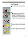
1
kÉï=~ë=çÑW= MUKOMNR `bob`=dìáÇÉ léÉê~íáåÖ=fåëíêìÅíáçåë båÖäáëÜ Operating Instructions = Table of contents Sirona Dental Systems GmbH Operating Instructions CEREC Guide Table of contents 1 2 3 4 5 2 General data............................................................................................................. 3 1.1 Structure of the document............................................................................. 1.1.1 Identification of the danger levels..................................................... 1.1.2 Formats and symbols used .............................................................. 3 3 4 1.2 Symbols used................................................................................................ 4 1.3 Intended use ................................................................................................. 5 1.4 Indications ..................................................................................................... 5 Safety instructions .................................................................................................... 6 2.1 Exclusion of liability ....................................................................................... 6 2.2 Limitations ..................................................................................................... 2.2.1 Limitations for CEREC Guide 1........................................................ 2.2.2 Limitations for CEREC Guide 2........................................................ 6 6 6 2.3 Prerequisites ................................................................................................. 2.3.1 Prerequisites for CEREC Guide 1 .................................................... 2.3.2 Prerequisites for CEREC Guide 2 .................................................... 7 7 7 2.4 Alternative SICAT OPTIGUIDE ..................................................................... 8 Product description................................................................................................... 9 3.1 Description of the CEREC Guide surgical guide ........................................... 3.1.1 CEREC Guide 1 ............................................................................... 3.1.2 CEREC Guide 2 ............................................................................... 9 10 11 3.2 Materials........................................................................................................ 12 Application................................................................................................................ 19 4.1 Application information .................................................................................. 19 4.2 Creating a CEREC Guide 1 .......................................................................... 4.2.1 Preparation of the scan template ..................................................... 4.2.2 Planning the implant and exporting the data.................................... 4.2.3 Milling the drill bit.............................................................................. 4.2.4 Creating the surgical guide .............................................................. 20 20 22 24 25 4.3 Creating a CEREC Guide 2 .......................................................................... 4.3.1 Optical impression............................................................................ 4.3.2 3D x-ray and implant planning ......................................................... 4.3.3 Design and development of the CEREC Guide 2 ............................ 4.3.4 Surgical intervention......................................................................... 27 27 28 30 31 Disinfection/sterilization of the surgical guide........................................................... 32 63 91 473 D3587 D3587.201.01.07.02 08.2015 Sirona Dental Systems GmbH 1 General data Operating Instructions CEREC Guide 1.1 Structure of the document 1 General data Please read this document completely and follow the instructions exactly. You should always keep it within reach. Original language of the present document: German. 1.1 Structure of the document 1.1.1 Identification of the danger levels To prevent personal injury and material damage, please observe the warning and safety information provided in the present operating instructions. Such information is highlighted as follows: An imminent danger that could result in serious bodily injury or death. WARNING A possibly dangerous situation that could result in serious bodily injury or death. CAUTION A possibly dangerous situation that could result in slight bodily injury. NOTICE A possibly harmful situation which could lead to damage of the product or an object in its environment. IMPORTANT Application instructions and other important information. Tip: Information on making work easier. 63 91 473 D3587 D3587.201.01.07.02 08.2015 3 båÖäáëÜ DANGER 1 General data Sirona Dental Systems GmbH 1.2 Symbols used Operating Instructions CEREC Guide 1.1.2 Formats and symbols used The formats and symbols used in this document have the following meaning: Requests you to do something. Prerequisite 1. First action step 2. Second action step or ➢ Alternative action Result ➢ Individual action step See "Formats and symbols used [ → 4]" Identifies a reference to another text passage and specifies its page number. ● List Designates a list. "Command / menu item" Indicates commands, menu items or quotations. 1.2 Symbols used Symbol Description NOTICE! Observe operating instructions! This product is a medical device in accordance with Council Directive 93/42/ EEC. Rx only CAUTION: According to US Federal Law, this product may be sold only to or by instruction of physicians, dentists, or licensed professionals. REF ABC123 Article number LOT ABC123 Batch number This product is intended for single use only unsterile NON STERILE 4 63 91 473 D3587 D3587.201.01.07.02 08.2015 Sirona Dental Systems GmbH 1 General data Operating Instructions CEREC Guide 1.3 Intended use 1.3 Intended use CEREC Guide is a surgical guide for dental implants individually manufactured by specialist dentists or dental technicians. The surgical guide is designed as an auxiliary device for dental surgery. The CEREC Guide requires the CEREC system and a 3D X-ray system from Sirona, such as GALILEOS or ORTHOPHOS XG 3D. 1.4 Indications båÖäáëÜ The CEREC Guide is used for dental implants that are completed with supported and managed surgical systems (refer to Materials [ → 12]). 63 91 473 D3587 D3587.201.01.07.02 08.2015 5 2 Safety instructions Sirona Dental Systems GmbH 2.1 Exclusion of liability Operating Instructions CEREC Guide 2 Safety instructions 2.1 Exclusion of liability The CEREC Guide surgical guide is an auxiliary device that is manufactured by a qualified dentist or dental technician. The user therefore bears full responsibility for the shape, suitability, and application of the template. Observe the processing instructions provided by the implant and drill manufacturers. 2.2 Limitations Different limitations and system requirements apply to the variations of the CEREC Guide 1 and CEREC Guide 2 surgical guide described further below. 2.2.1 Limitations for CEREC Guide 1 A CEREC Guide 1 can be manufactured by you as a clinician or technician by means of an MC X or MC XL milling unit. The CEREC Guide 1 is not a fully automatic solution. It cannot be compared to a surgical guide that has been manufactured centrally based on your design. A CEREC Guide 1 must not be used for situations which extend over more than one quadrant. No more than two implants should be set per template. The thermoplast process is only approved for the extraoral creation of the scan template (on a model). It is not possible to use the inLab MC X5 device. 2.2.2 Limitations for CEREC Guide 2 A CEREC Guide 2 can be manufactured by you as a clinician or technician by means of an MC X / MC XL milling unit or an inLab MC X5. The CEREC Guide 2 is not a fully automatic solution. It cannot be compared to a surgical guide that has been manufactured centrally based on your design. A CERED Guide 2 must always be supported by the residual teeth. It is not possible to support the guide through the mucous membrane alone. When working on a MC X or MC XL milling unit, no more than one implant can be created per template. 6 63 91 473 D3587 D3587.201.01.07.02 08.2015 Sirona Dental Systems GmbH 2 Safety instructions Operating Instructions CEREC Guide 2.3 Prerequisites 2.3 Prerequisites 2.3.1 Prerequisites for CEREC Guide 1 To create the optical impression and export a prosthetic proposal: ● CEREC SW 4.0.2 or inLab SW 4.0.2 ● Open GALILEOS Implant license To create a 3D X-ray volume and for implant planning: ● GALILEOS, ORTHOPHOS XG 3D or ORTHOPHOS SL 3D ● Sidexis XG or Sidexis 4 ● Galaxis 1.9 ● Implant planning software "GALILEOS Implant", V1.9 with SP1 or V1.9.2 båÖäáëÜ To develop the CEREC Guide 1: ● CEREC SW 4.0.2 or inLab SW 4.0.2 ● CEREC only: Open GALILEOS Implant license ● MC X or MC XL grinding unit CAUTION Errors when setting the tooth numbering When setting the tooth numbering to the American (ADA) pattern, an error in GALILEOS Implant V1.9 can cause invalid export data. This can cause the tooth number to be mixed up and hence injure the patient. ➢ Version 1.9 with SP1 or a higher version is mandatory! 2.3.2 Prerequisites for CEREC Guide 2 To create the optical impression and export a prosthetic proposal: ● CEREC SW 4.3.1 or inLab SW 15.0 incl. implant module ● CEREC only: Open GALILEOS Implant license To create a 3D X-ray volume and for implant planning: ● GALILEOS, ORTHOPHOS XG 3D or ORTHOPHOS SL 3D ● Sidexis XG or Sidexis 4 ● Galaxis 1.9.2 ● Implant planning software "GALILEOS Implant", V1.9.2 To develop the CEREC Guide 2: ● CEREC SW 4.4 or inLab SW 15.0 incl. implant module ● CEREC only: Open GALILEOS Implant license ● MC X or MC XL grinding unit with milling function or inLab MC X5 63 91 473 D3587 D3587.201.01.07.02 08.2015 7 2 Safety instructions 2.4 Alternative SICAT OPTIGUIDE Sirona Dental Systems GmbH Operating Instructions CEREC Guide 2.4 Alternative SICAT OPTIGUIDE If there is any uncertainty at any time or the situation is deemed to be critical, the surgery must not be completed under any circumstances. In such cases an optical impression (CEREC) of the situation must be imported into the X-ray volume. This can then be used to order a SICAT OPTIGUIDE; refer to the "GALILEOS Implant" manual from version 1.9. 8 63 91 473 D3587 D3587.201.01.07.02 08.2015 Sirona Dental Systems GmbH 3 Product description Operating Instructions CEREC Guide 3.1 Description of the CEREC Guide surgical guide 3 Product description 3.1 Description of the CEREC Guide surgical guide CEREC Guide is a precise surgical guide which is individually manufactured in your practice or laboratory. The manufacturing process is fast and incurs comparatively low costs. It is a prerequisite that the location of one or more implants has been planned using a 3D X-ray scan (DVT) and that location is to be transferred to the actual jaw. CEREC Guide is a tool that is intended to help the treating physician set the implant. CEREC Guide functions as a surgical guide, which is placed on the residual teeth or another supporting structure in the mouth and acts as a mechanical guide for the drills used. Together with CEREC Guide, drill keys are also used as reducing bushes, which enable the use of drills with smaller diameters. A distinction is made between two versions: ● CEREC Guide 1: A surgical guide comprising a template element made of thermoplastic material and a drill bit, with the prerequisite that a DVT has been created using an X-ray reference unit. Creating an optical impression of the situation in the mouth is optional here. ● CEREC Guide 2: A surgical guide, made from a workpiece, based on an overlay of an optical scan of the situation in the mouth and a DVT image, without using an x-ray reference unit. 63 91 473 D3587 D3587.201.01.07.02 08.2015 9 båÖäáëÜ The individually manufactured surgical guide is part of the integrated implant plan and surgical implementation using CAD/CAM and 3D X-ray systems from Sirona. 3 Product description Sirona Dental Systems GmbH 3.1 Description of the CEREC Guide surgical guide 3.1.1 Operating Instructions CEREC Guide CEREC Guide 1 The key steps for manufacturing and using a CEREC Guide 1 are as follows: 1. Creating a scan template A model of the situation in the mouth is created. A template element is formed of thermoplastic material on the residual teeth in this model. A reference unit is placed in the approximate location of the planned implant in the template element. The position of the scan template and reference unit in the residual teeth is clearly defined in this way. 2. Take DVT exposure The patient wears the scan template while the DVT exposure is taken. In the DVT scan, the markers contained in the reference unit are visible along with the normal information, upon which the implant planning is based. In this way, the location of the planned implant in relation to the reference unit is determined. 3. Create drill bit The prefabricated bore in the CEREC Guide Bloc is in line with the drill channel. Based on the planning data, a drill bit is ground out of a CEREC Guide Bloc so that the external form of the drill bit is in line with that of the reference unit and the prefabricated drill hole matches the planned implant axis. In addition, the height of the drill bit is adjusted based on the planning data such that the guided drill must be moved to the stop point in order to reach the desired depth. The reference unit is removed from the scan template and replaced by the drill bit. The drilling template is therefore created from the scan template. 4. Surgical intervention The drilling template now consists of template elements made of thermoplastic material using a drill bit, which prescribes the direction of the implant and has a depth stop. The drilling template is placed in the patient’s mouth. According to the drilling protocol of the manufacturer of the implant, different bores with drills with different guide diameters. CEREC Guide drill keys are used for this and serve as reducing bushes for the respective drill diameter. The mechanical guide of the drill, with a prescribed direction and depth, enables the treating physician to change the planned implant into reality. 10 63 91 473 D3587 D3587.201.01.07.02 08.2015 Sirona Dental Systems GmbH 3 Product description Operating Instructions CEREC Guide 3.1 Description of the CEREC Guide surgical guide 3.1.2 CEREC Guide 2 The key steps for manufacturing and using a CEREC Guide 2 are as follows: 1. Optical scan An optical scan of the situation in the mouth is created (either intraoral or using a model). A suitably large area is encompassed, on which the drilling template can later support itself. A restoration is designed, which initially enables the subsequent implant planning in terms of prosthetic aspects. This information is exported as a *.SSI file. 3. Implant planning Optical scan (Import of the *.SSI file) and DVT scan are superimposed in GALILEOS Implant using striking features, which are present in both scans (such as the residual teeth). The implant planning is performed based on all of this information. Therefore the location of the guide bushing of the drill is also defined in relation to the residual teeth (or other supporting structures). The planning data is exported as a *.CMG.DXD file. 4. Creating the drilling template After importing the *.CMG.DXD file in CEREC or inLab, a drilling template is designed, which can be placed on suitable supporting structures and has an opening at a planned location, through which the drill is to be fed. The single-piece template is create from PMMA, for example by milling. 5. Surgery The drilling template is placed in the patient’s mouth. According to the drilling protocol of the manufacturer of the implant, different bores with drills with different guide diameters. Drill keys are used for this and serve as reducing bushes for the respective drill diameter. The mechanical guide of the drill, with a prescribed direction and depth, enables the treating physician to change the planned implant into reality. 63 91 473 D3587 D3587.201.01.07.02 08.2015 11 båÖäáëÜ 2. DVT exposure A DVT scan is performed, which forms the basis for the implant planning. 3 Product description Sirona Dental Systems GmbH 3.2 Materials Operating Instructions CEREC Guide 3.2 Materials Thermoplast Thermoplast Thermoplast is only required to manufacture the template element for CEREC Guide 1. Thermoplast is a rigid plastic. When heated with hot water it becomes soft and easily pliable. Recommended materials: ● Hydroplastic from TAK Systems ● Luxaform from DMG Dental Important: When handling these materials, please observe the relevant application descriptions from the manufacturers. CEREC Guide Blocs 12 63 91 473 D3587 D3587.201.01.07.02 08.2015 Sirona Dental Systems GmbH 3 Product description Operating Instructions CEREC Guide 3.2 Materials CEREC Guide Blocs and inCoris PMMA guide CEREC Guide Blocs are made of clear Plexiglas® GS 0F00. The CEREC Guide Blocs S, M and L intended to create a CEREC Guide 1 are delivered together with a reference unit of the appropriate size. These blocks include a prefabricated drill hole to incorporate a CEREC guide drill key of the relevant size (S, M or L). These blocks can be processed using a grinder on the MC X and MC XL grinding units. CEREC Guide Blocs S, M and L are not suitable for use with the CEREC guide drill key set C for Camlog®. The CEREC Guide Blocs medi and maxi are intended to manufacture a CEREC Guide 2. These blocks are processed in a milling process on the MC X and MC XL grinding units. All parts are provided unsterilized and are intended for single use only. Designation REF Contents CEREC Guide Blocs S 63 75 054 2x Reference units S (orange) Notes CEREC Guide 1 only 2x CEREC Guide Blocs S CEREC Guide Blocs M 63 75 062 2x Reference units M (white) CEREC Guide 1 only 2x CEREC Guide Bloc M CEREC Guide Blocs L 63 75 070 2x Reference units L (gray) CEREC Guide 1 only 2x CEREC Guide Bloc L CEREC Guide Bloc medi 64 66 564 1x CEREC Guide Bloc medi Length: 55 mm, Width: 40 mm, Height: 22 mm MC X only, CEREC Guide 2 only CEREC Guide Bloc maxi 64 47 093 1x CEREC Guide Bloc maxi Length: 85 mm, Width: 40 mm, Height: 22 mm MC XL only, CEREC Guide 2 only inCoris PMMA guide disc 22 65 51 324 1x inCoris PMMA guide disc 22 Ø 98.5 mm, height 22 mm inLab MC X5 only, CEREC Guide 2 only Reference units 63 91 473 D3587 D3587.201.01.07.02 08.2015 13 båÖäáëÜ The inCoris PMMA guide is intended for production of CEREC Guide 2 and is processed on the inLab MC X5 in a milling process. 3 Product description Sirona Dental Systems GmbH 3.2 Materials Operating Instructions CEREC Guide Reference units Reference units are only required to manufacture the scan template for CEREC Guide 1. Size Color Width (mesial/distal) Shifting mesial/distal Small (S) Orange 6 mm max. 1.5 mm Medium (M) White 7.3 mm max. 2 mm Large (L) Gray 11 mm max. 4mm The reference units can only ever be used with a CEREC Guide Bloc of the same size. The basal surface of the reference unit corresponds to the basal surface of the drill bit, from which the CEREC Guide Bloc is created. As the drill channel must be fully within the basal surface, the plan states a maximum value by which the implant can be shifted in the mesial-distal direction. Reference units are made of Hostaform® MT 12U01 plastic and are supplied unsterilized. Seven glass soda balls are located in the reference units as radio-opaque markers. Drill key sets Drill key The drill keys provided by the implant manufacturers are not compatible with CEREC Guide. Use the Sirona drill key in place of the original drill key from the implant manufacturer: CEREC Guide Drill Keys. CEREC Guide Pilot Drill Keys are only suitable for guiding pilot drills. CEREC Guide Drill Keys Sets also contain additional drill keys to guide the drills for widening drilled holes. Guided insertion of implants using CEREC Guide is not supported. All CEREC Guide Drill Keys are only suitable for use with the following surgical kits from the respective implant manufacturers. CEREC Guide drill keys are made of grade 1.4301 stainless steel and are supplied unsterilized. 14 63 91 473 D3587 D3587.201.01.07.02 08.2015 Sirona Dental Systems GmbH 3 Product description Operating Instructions CEREC Guide 3.2 Materials Designation REF CEREC Guide 64 62 530 Pilot Drill Keys 2.0 Suitable for surgical kit AstraTech: Facilitate®, pilot drill only Biomet 3i: Navigator®, pilot drill only Nobel Biocare: For the pilot drill only ● Branemark® System Guided Surgery Kit ● NobelReplace® Straight Guided Surgery Kit ● NobelActive Guided Surgery Kit CEREC Guide 64 62 563 Pilot Drill Keys 2.2 Straumann®: Guided Surgery Kit, pilot drill only Sirona CEREC 63 73 711 Guide Drill Key Set ST Straumann®: Sirona CEREC 63 73 943 Guide Drill Key Set NB Nobel Biocare:* Guided Surgery Kit ● Branemark® System Guided Surgery Kit ● NobelReplace® Straight Guided Surgery Kit ● NobelReplace® Tapered Guided Surgery Kit ● NobelActive Guided Surgery Kit Sirona CEREC 63 73 950 Guide Drill Key Set AT AstraTech: Facilitate® Sirona CEREC 63 73 968 Guide Drill Key Set B Biomet 3i: Navigator® Sirona CEREC 63 73 729 Guide Drill Key Set C Camlog guided drills** *Noble Biocare: The drills for WP and 6.0 implants are not supported. **Not suitable for use with the CEREC Guide Blocs S, M or L (CEREC Guide 1) 63 91 473 D3587 D3587.201.01.07.02 08.2015 15 båÖäáëÜ ● NobelReplace® Tapered Guided Surgery Kit 3 Product description Sirona Dental Systems GmbH 3.2 Materials Operating Instructions CEREC Guide Each drill key is marked with the information for the sleeve diameter and drill diameter: ● Sizes S, M and L state the compatibility with the planned sleeve diameter. In the case of CEREC Guide 1, this is prescribed by the selection of the reference unit. If, for example, a scan template with a white reference unit is generated (size M), then a CEREC Guide Bloc M is used for the drill bit. In this case, only drill bits labeled with an M are suitable. In the case of CEREC Guide 2, when planning the sleeve in GALILEOS Implant, a determination is made as to whether the drill key size S, M or L is used. ● The numerical value specified corresponds to the inside diameter of the drill key in mm. This value does not correspond to the drill diameter in all systems. The following table specifies which original manufacturer drill key corresponds to the respective drill key from the Sirona drill key set. Overview of drill keys Drill set Original key designation Ø drill = Ø inside tray S (Ø ≤ 3.5) M (Ø ≤ 4.3) L (Ø ≤ 5.0) NP Ø 2 2.0 X X X 2.2 X X X Ø 2.2 mm 2.2 X X X Ø 2.8 mm 2.8 X X X Ø 3.5 mm 3.5 X X X Ø 4.2 mm 4.2 - X X CEREC Guide Pilot Drill Keys 2.0 The set contains three drill keys Branemark System Guided Surgery Kit NobelReplace Straight Guided Surgery Kit NobelReplace Tapered Guided Surgery Kit NobelActive Guided Surgery Kit Astra Tech Facilitate 2.0 Biomet 3i Navigator 2.0 CEREC Guide Pilot Drill Keys 2.2 The set contains three drill keys Straumann Ø 2.2 mm CEREC Guide Drill Key Set ST (for Straumann) The set contains 11 drive keys in 2 sterilized boxes. Guided drills CEREC Guide Drill Key Set NB (for Nobel Biocare) The largest drill diameter for the insertion of WP and 6.0 implants is not supported. The set contains 25 drive keys in 3 sterilized boxes. 16 63 91 473 D3587 D3587.201.01.07.02 08.2015 Sirona Dental Systems GmbH 3 Product description Operating Instructions CEREC Guide 3.2 Materials Drill set Original key designation Ø drill = Ø inside tray S (Ø ≤ 3.5) M (Ø ≤ 4.3) L (Ø ≤ 5.0) Branemark System Guided Surgery Kit NP Ø 2 2.0 X X X 2.8 X X X 3.0 X X X 3.2 X X X RP Ø 3.4 3.4 X X X RP Ø 3.6 3.6 - X X 6/WP Ø 3.8 3.8 - X X RP - NP 4.1 - X X 4.2 - X X 6/WP Ø 4.6 4.6 - - X 6/WP Ø 5 5.0 - - X 2.0 2.0 X X X 3.2 3.2 X X X 3.35 3.35 X X X 3.7 3.7 - X X 3.85 3.85 - X X 4.2 4.2 - X X 4.7 4.7 - - X 4.85 4.85 - - X NobelReplace Straight Guided Surgery Kit NobelReplace Tapered Guided Surgery Kit NobelActive Guided Surgery Kit RP Ø 2 6/WP Ø 2 NP Ø 2.8 RP Ø 2.8 NP Ø 3 RP Ø 3 6/WP Ø 3 RP Ø 3.2 båÖäáëÜ NP Ø 3.2 6/WP Ø 3.6 6/WP - NP 6/WP Ø 4.2 RP Ø 4.2 6/WP - RP CEREC Guide Drill Key Set AT (for Astra Tech Facilitate) The set contains 17 drive keys in 2 sterilized boxes. Facilitate CEREC Guide Drill Key Set B (for Biomet 3i Navigator) The set contains 16 drive keys in 2 sterilized boxes. 63 91 473 D3587 D3587.201.01.07.02 08.2015 17 3 Product description Sirona Dental Systems GmbH 3.2 Materials Operating Instructions CEREC Guide Drill set Original key designation Ø drill = Ø inside tray S (Ø ≤ 3.5) M (Ø ≤ 4.3) L (Ø ≤ 5.0) Navigator 2.0 2.0 X X X 2.75 2.75 X X X 3.0 3.0 X X X 3.25 3.25 X X X 3.85 3.85 - X X 4.25 4.25 - X X - - X CEREC Guide Drill Key Set C (for Camlog)* The set contains 3 of the same drive keys in 1 sterilized box. Camlog 4.5 (sleeve) 4.5 * Not suitable for use with the CEREC Guide Blocs S, M or L (CEREC Guide 1) 18 63 91 473 D3587 D3587.201.01.07.02 08.2015 Sirona Dental Systems GmbH 4 Application Operating Instructions CEREC Guide 4.1 Application information 4 Application 4.1 Application information ● The CEREC Guide must only be used in cases that have been planned by a qualified dentist using the implant planning software GALILEOS Implant or SICAT Implant. ● The drill keys listed under the “Materials [ → 12]” section are mandatory for every drilling process. Under no circumstances must the drill be controlled with just the drill bit, without the use of a drill key. ● The drill must only be removed from the drill key or drill bit once it has come to a complete standstill. Important: Always observe the size specifications on the drill keys, reference units, blocks, and drill. Example: The MØ2.2 mm drill key is only permissible for 2.2 mm drills following the application of a medium-sized reference unit. ● The area around the implant must be amply sprayed and cooled during the drilling process. The temperature in the drill channel must be maintained to a minimum to prevent the hard tissue from denaturing. No remnants of tissue must remain in the area around the implant. ● All materials that are used intraorally must be disinfected before use and safeguarded against aspiration when being used. ● The materials “Thermoplast”, “CEREC Guide Blocs”, “inCoris PMMA guide disc 22” and “Reference units” (see “Materials [ → 12]”) are intended for single use only and are not supplied in sterile packaging; also refer to “Disinfection/sterilization of the surgical guide [ → 32]”. ● Please protect the surgical guide from direct sunlight and high temperatures to prevent it from deforming. Check the surgical guide before the operation. Do not use any heat-based methods to disinfect or sterilize (e.g. autoclaves), as this can cause the surgical guide to deform. 63 91 473 D3587 D3587.201.01.07.02 08.2015 19 båÖäáëÜ ● The drill must only be operated once a suitable drill key is tightly fitted in the drill bit and the tip of the drill is fully inserted through the drill key in the apical direction. 4 Application Sirona Dental Systems GmbH 4.2 Creating a CEREC Guide 1 Operating Instructions CEREC Guide 4.2 Creating a CEREC Guide 1 4.2.1 Preparation of the scan template The heated Thermoplast is used to create an imprint of the implant area. The Thermoplast fixes the reference unit inserted on the required drilling position. The 3D X-ray can then be taken. ✔ The "implant" indication is then completed; refer to Indications [ → 5]. 1. Optional: Where applicable, complete an initial CEREC scan to plan the prosthetics. IMPORTANT Observing the undercuts Check the location of the implant for any problematic undercuts. ➢ If necessary, manually even these out, for example, by using silicone-based material. Do not use wax as it can melt when it comes into contact with warm Thermoplast. ➢ The template must be able to be fitted and removed again with justifiable force. 2. Create a plaster model and block off any critical areas such as undercuts using a suitable material. This material must not be heat sensitive. 3. Prepare a reference unit for use. Select a size that is in accordance with the location of the implant. IMPORTANT Reference units - sizes available Always use the largest possible reference unit that will fit in the gap. The reference unit selected must also correspond to the maximum drill diameter to be used. 4. Place the Thermoplast material in a sufficiently large glass bowl. 5. Bring the water to the boil and pour the water directly over the Thermoplast so that it is fully covered. Thermoplast melts at 90°C (195°F) and becomes a transparent, easily pliable mass. The Thermoplast is completely transparent after two to three minutes (depending on the manufacturer). 6. CAUTION! Risk of burning! Do not place your hands in the water bath. Use a tool to remove the material from the water. Remove the material from the water, for example, using metal tweezers. 20 63 91 473 D3587 D3587.201.01.07.02 08.2015 Sirona Dental Systems GmbH 4 Application Operating Instructions CEREC Guide 4.2 Creating a CEREC Guide 1 IMPORTANT Processing time Thermoplast hardens as it cools and also loses its transparency. After removing it from the water bath you will have one to three minutes to process the Thermoplast. Hardened Thermoplast can be reheated in the water bath. 7. Depending on the type of plaster: Moisten the plaster model so that the Thermoplast can be removed easily. CEREC Stone BC generally does not need to be moistened as Thermoplast does not connect with the material. 8. In accordance with the location of the implant, shape a 2-3 mm thick plate using the Thermoplast. 10. Optional: Before placing the Thermoplast on the model, you can use the reference unit to create a hole in the Thermoplast. This facilitates the later removal of the residual material between the reference unit and gingiva. 11. Position the Thermoplast on the prepared area. Create an imprint by applying light pressure. The Thermoplast must be pressed closely on the location of the implant and enclose it fully. Following the casting process, the template must have a stable fit. 12. Press the reference unit into the required drilling position in the Thermoplast that is still soft. IMPORTANT Positioning the reference unit The reference unit must be pushed as far in to the apical direction as possible so that it rests on the gingiva. The template and the reference unit must not be able to be moved. The risk of any displacement caused by the tongue/cheek must be avoided. The Thermoplast must not cover the reference unit. However, it must surround the reference unit up to the small undercut on the shoulder. If the Thermoplast moves too far in a buccal or lingual direction when the reference unit is pushed in, it must be pushed back on to the reference unit. If two implants are to be located next to each other, align a scanbody orally and according to the vestibular. 63 91 473 D3587 D3587.201.01.07.02 08.2015 21 båÖäáëÜ 9. Shape it over the location of the implant in such a way that at least the distal and mesial adjacent teeth are covered with Thermoplast. 4 Application Sirona Dental Systems GmbH 4.2 Creating a CEREC Guide 1 Operating Instructions CEREC Guide 13. To accelerate the hardening process of the Thermoplast, you can cool it with water or a spray. 14. Remove the scan template from the model once it is completely hardened. Tip: You can prevent the opposite jaw from moving during the X-ray. Insert additional Thermoplast to the side of the position of the implant to create a surface for the antagonist. Apply slight pressure to the soft mass. Once the material has hardened, the patient can bite down on it during the X-ray. Remove this Thermoplast again after the X-ray. WARNING Before using the scan template in the mouth, it must first be disinfected with a suitable disinfectant. Please also observe the cleaning specifications provided by the Thermoplast manufacturer. Thermoplasts can generally not be autoclaved. 4.2.2 Planning the implant and exporting the data 1. Insert the first scan template into the patient's mouth. Check that the seating of the template is stable and accurate. Ensure that the template and reference unit cannot move during the X-ray. 2. Take an X-ray of the patient with the scan template in place. Please refer to the operating instructions for your Sirona 3D X-ray device. 3. Remove the scan template from the patient's mouth immediately after the X-ray. 4. Open the GALILEOS Implant software and load the patient's data record. 5. To plan the implant, set the sleeve system, detect the unit, and to plan the sleeve position D2 follow the instructions provided in the "GALILEOS Implant" operator's manual. Follow the instructions provided in the chapter "Exporting plan for third-party processing” (GALILEOS Implant V1.9 with SP1) or the chapter “Exporting plans for third-party processing using reference units” (GALILEOS Implant 1.9.2). Select the sleeve system "Sirona - CEREC Guide Drill Keys (CEREC Guide 1)" or "Sirona - Cerec". Estimate the required drill length. It should be longer than the combined lengths: implant length + 6 mm + X (clearance between implant shoulder and bottom edge of the drill key). Enter the value for D2. It is calculated from the length of the longest drill used, subtracting 1 mm. (D2 = drill length - 1 mm). The D1 value can be ignored. 6. Finally, check whether the clearance (orange line) between the bottom side of the reference unit (orange outline) and the top of the drill bit (green line) is ≥ 5mm. If the value is less than 5 mm, select a longer drill and adjust the D2 value accordingly. 22 63 91 473 D3587 D3587.201.01.07.02 08.2015 Sirona Dental Systems GmbH 4 Application 4.2 Creating a CEREC Guide 1 A Drill B Drill key C Implant D2 D2 = implant length + 5mm + clearance between implant shoulder and bottom edge of the drill key båÖäáëÜ Operating Instructions CEREC Guide D2 = F + 5mm + X E Drill length F Implant length X Clearance between implant shoulder and bottom edge of the drill key 7. Export the data for CEREC. Follow the instructions provided in the sub-section "Exporting the plan" in the "GALILEOS Implant" operator's manual. 63 91 473 D3587 D3587.201.01.07.02 08.2015 23 4 Application Sirona Dental Systems GmbH 4.2 Creating a CEREC Guide 1 Operating Instructions CEREC Guide 4.2.3 Milling the drill bit ✔ The CEREC SW software has been started. ✔ Open GALILEOS Implant license is available. 1. Import the data in to CEREC SW. To do so, click on "Import Case..." in the system menu. Ensure that the file type filter in the bottom right corner of the "Open" dialog is set to CEREC Guide cases. 2. Select the file that you have just exported from GALILEOS Implant. Tip: In standard mode, GALILEOS Implant exports CEREC Guide cases to C:\ThirdPartyExport The milling preview is opened. 3. Select the desired milling unit as required. The Step Bur 20 and Cylinder Pointed Bur 20 millers are used. 4. Insert the correct CEREC Guide Bloc into the milling chamber. 5. Start the milling process. The drill bit is created. 6. Remove the drill bit from the block. Ensure that the sprue position on the drill bit is as flush as possible when disconnected. The best results are achieved by using cross-toothed plastic milling tools at a low speed. 24 63 91 473 D3587 D3587.201.01.07.02 08.2015 Sirona Dental Systems GmbH 4 Application Operating Instructions CEREC Guide 4.2 Creating a CEREC Guide 1 4.2.4 Creating the surgical guide The scan template is now used to create a surgical guide, by removing the reference unit(s) and replacing it/them with the suitable drill bit(s). Tip: In the event of several implants, the drill bits can be distinguished by the tooth number that is engraved on the drill bit. 2. Ensure that there is no Thermoplast residue under the drill bit. The drill channel must not be blocked. Use a sharp scalpel. Tip: Thin areas of the hardened Thermoplast can be cut using a scalpel. Stronger parts can be processed with a very slow turning handpiece, such as a three-edged cutter for processing thermoforming films. When processing, use a water spray for cooling purposes. If the instrument causes the Thermoplast to become too warm, the plastic will become liquid again, deform, and block the instrument. Therefore only use the handpiece in areas that are too thick for the scalpel. 3. Use the model to ensure that adequate drainage of the rinsing liquid is guaranteed during the operation. Adapt the template, if necessary, by adding holes for rinsing purposes. 4. Insert the drill bit into the template. Attach the drill bit with adhesive that is approved for intraoral applications (e.g. LOCTITE® 4601). 5. Disinfect the surgical guide before you use this in the patient's mouth. 6. Reinsert the surgical guide into the patient's mouth. 7. Select the drill key required which corresponds to the drills specified by the manufacturer of the guided system. Also adhere to the drill key assignment table in the chapter regarding "Drill key sets" in Materials [ → 12]). 63 91 473 D3587 D3587.201.01.07.02 08.2015 25 båÖäáëÜ 1. Carefully twist the reference unit to remove it from the scan template. 4 Application Sirona Dental Systems GmbH 4.2 Creating a CEREC Guide 1 Operating Instructions CEREC Guide CAUTION This checklist must be fully verified before the drilling process: ➢ Drill bit is fixed in the template. ➢ Surgical guide clicks into the correct position ➢ Once in place, the surgical guide is secured tightly (no "play" or "wobbling") ➢ The drill channel guide corresponds to the implant plan If one of these points does not apply, an optical impression (CEREC) of the situation must be imported into the X-ray volume and a SICAT OptiGuide must be ordered; refer to the "GALILEOS Implant" manual. 8. Start the implantation in accordance with the instructions provided by your drill supplier. 26 63 91 473 D3587 D3587.201.01.07.02 08.2015 Sirona Dental Systems GmbH 4 Application Operating Instructions CEREC Guide 4.3 Creating a CEREC Guide 2 4.3 Creating a CEREC Guide 2 4.3.1 Optical impression 1. Scan the situation in the mouth either intraorally or using a model. The following applies at least to all areas, which are intended to later serve as a support for the CEREC Guide 2. The surface scan is also used for the overlay of the x-ray volume. NOTICE Note that the drilling template cannot be bigger than the scanned area. 2. Design a restoration at the planned implant position. Mark the emergence profile of the tooth on the gingiva in manual entry mode. 3. Export the data record using in *.SSI format. 63 91 473 D3587 D3587.201.01.07.02 08.2015 27 båÖäáëÜ Avoid holes in the scan. Otherwise, no locating surface for the CEREC Guide 2 can be determined at these points. 4 Application Sirona Dental Systems GmbH 4.3 Creating a CEREC Guide 2 Operating Instructions CEREC Guide 4.3.2 3D x-ray and implant planning A DVT scan can be performed before or after the optical impression. Make sure that there are no metal artifacts in the scan, as these may hinder the overlay of optical data with the x-ray volume or even make it impossible. Do not scan the patient at the final bite position, but rather with a slightly opened jaw. Remove all removable metal parts in the opposing jaw (e.g. prosthetics). If possible, record 3/4 of the arch of the jaw. This increases the likeliness that teeth free from artifacts can be used for registration. To produce a CEREC Guide 2, the import of the previously created *.SSI data record in GALILEOS Implant is necessary. The optical surface scan is superimposed over the X-ray volume. This makes it possible to determine the implant location while also considering the soft tissue and prosthetic planning. CAUTION Check that the optical impression is correctly aligned with the X-ray data record. If multiple implants are to be planned, multiple *.SSI data records must be imported. To plan the implant follow the instructions provided in the "GALILEOS Implant 1.9.2" operator's manual. Follow the instructions provided in Appendix C.2 "Exporting plans for third-party processing using optical impressions". Select Sirona - CEREC Guide Drill Keys as the sleeve system (CEREC Guide 2, SICAT Surgical Guides). You then have three sleeves available to choose from, which match the CEREC Guide drill keys S, M or L respectively. If, for example only one pilot hole is to be created, the selection of size S is sufficient (apart from Camlog). The specification of a depth stop is oriented on the length of the drill used. The planned position is reached when drilling once the mechanical stop of the drill reaches the drill key or (if the drill does not have a stop) the length marking on the drill is lowered to the upper side of the drill key. 28 63 91 473 D3587 D3587.201.01.07.02 08.2015 Sirona Dental Systems GmbH 4 Application 4.3 Creating a CEREC Guide 2 A Drill D Bones B CEREC Guide Drill Key E Tooth C Gingiva F CEREC Guide 2 båÖäáëÜ Operating Instructions CEREC Guide In the GALILEOS Implant software, the depth stop is to be entered using the D2 value. The D2 value is defined as the distance from the side of the drilling template to the apical top of the implant. As the drill strikes the 1 mm thick drill key, the D2 value to be set results from the length of the drill minus one millimeter (D2 = drill length – 1mm). The statement of the D1 value is to be ignored. After entering the D2 value, the sleeve is visualized above the implant at the relevant height. NOTICE When selecting the bushing, ensure that it does not collide with neighboring teeth and the drill key and the drill itself can be introduced without a collision. Note that selecting a smaller sleeve may limit the use of larger drill diameters. The Camlog Guided System is only compatible with sleeve L. If the representation of the underside of the sleeve cuts the scan shown as the yellow line, this indicates that the position of the drill key is at least partially subgingival. Multiple implants and sleeve positions are planned in the same way. It is possible to export this as a file. Export the plan for “processing by thirdparty providers by way of optical impressions” as a .CMD.DXD file. 63 91 473 D3587 D3587.201.01.07.02 08.2015 29 4 Application Sirona Dental Systems GmbH 4.3 Creating a CEREC Guide 2 Operating Instructions CEREC Guide 4.3.3 Design and development of the CEREC Guide 2 By selecting "Import" , you can switch the directly load the *.CMG.DXD file. Phase ADMINISTRATION If the plan contains multiple implants, these will be treated as multiple separate restorations. Select the machine type for development. This determines the possibilities for further processing. Phase MODEL If the original scan is presented, which was also the basis for the implant planning. All areas, which are not intended to serve as a support for the CEREC Guide 2 should be cut. This includes, for example, larger areas of gingiva outside the planned implant position. Parts of the residual teeth may also be discarded if they are not required for support. Note that a longer template is easier to hold in position with one finger and ensures secure support. This applies to free-end situations in particular. Phase DESIGN The position and shape of the sleeve cannot be changed using general design tools. If a sleeve is shown in red, parts of it are subgingival. Determine whether these areas are to be cut away (e.g. to enable the unhindered placement on a model) or are to be left as they are. They color of the sleeve then turns green. Optionally, you can create side access to introduce the drill from the side. This is only recommended for reasons of stability where required due to a lack of space. After calculating the template element and if necessary orienting it in the block, you have the option of creating viewing panels, which you can use to check the fitting of the template even during the surgical intervention. You can then still adapt the design of the template by cutting away any problematic areas. Phase MILL Where necessary, ensure that you have activated "Configuration" the option "MC XL Milling" . So that the milling process runs without interruption, ensure where necessary that milling tools with a sufficient service life are used, the water filter has been cleaned and there is sufficient water in the tank. After milling, ensure that no shavings enter into the tank during the cleaning process, as these can quickly clog the water filter. 30 63 91 473 D3587 D3587.201.01.07.02 08.2015 Sirona Dental Systems GmbH 4 Application Operating Instructions CEREC Guide 4.3 Creating a CEREC Guide 2 4.3.4 Surgical intervention CAUTION 1. Perform the implantation according to the implant manufacturer’s instructions. 2. Fix the template in the mouth, holding it in position with your finger if necessary. Tip: If you have created access to the drill from the side due to a lack of space, first place the CEREC Guide 2 into the patient’s mouth. Then guide the drill key through the drill and push it upwards. Now guide the drill through the side into the sleeve position and lower the drill key to the stop point. Then start drilling. 63 91 473 D3587 D3587.201.01.07.02 08.2015 31 båÖäáëÜ Remove burrs and round sharp corners on the template element. Check that the template fits correctly beforehand where necessary using a model. The template element must be completely slid open and must not wobble. Clean and disinfect the CEREC Guide 2 as described in the chapter below. Select the drill key required which corresponds to the drills specified by the manufacturer of the guided system. Also adhere to the drill key assignment table. Ensure that the drill key can fully enter the drill hole and stops there without wobbling. 5 Disinfection/sterilization of the surgical guide Sirona Dental Systems GmbH Operating Instructions CEREC Guide 5 Disinfection/sterilization of the surgical guide Disinfecting The “inCoris PMMA guide disc 22” and CEREC Guide Blocs including the reference units are supplied unsterilized and must be disinfected with standard practice equipment. Recommended disinfectant e.g. "Dentavon® Liquid" from Schülke & Mayr Please also observe the cleaning specifications provided by the Thermoplast manufacturer. Sterilizing The drill key (A) and terminal strip (B) are supplied unsterilized and must be steam sterilized using a standard practice sterilization device. The drill keys must be sterilized before being used in the mouth. Furthermore, the locally applicable legal regulations and the hygiene standards applicable for a dental practice must be observed. Only use the approved sterilization procedures specified below to sterilize the drill keys. Observe the sterilization parameters. Steam sterilization can be performed with the fractionated vacuum or the gravitation method. The sterilization time is 5 minutes at 132°C / 270°F and 15 minutes at 121°C / 250°F. Steam sterilization may be performed only using devices that comply with EN 13060 or EN 285 standards. Sterilization methods must be validated in compliance with EN ISO 17664. The responsibility for the sterility of the drill keys lies with the user. It must be ensured that only suitable devices, materials and product-specifically validated methods are used to perform sterilization. It must be ensured that the methods used have been validated. The equipment and devices must be properly maintained and serviced at regular intervals. The manufacturer (dentist/dental technician/dental assistant) must inform the user about the required sterilization process before insertion in the patient's mouth! 32 63 91 473 D3587 D3587.201.01.07.02 08.2015 tÉ=êÉëÉêîÉ=íÜÉ=êáÖÜí=íç=ã~âÉ=~åó=~äíÉê~íáçåë=ïÜáÅÜ=ã~ó=ÄÉ=êÉèìáêÉÇ=ÇìÉ=íç=íÉÅÜåáÅ~ä=áãéêçîÉãÉåíëK «=páêçå~=aÉåí~ä=póëíÉãë=dãÄe=OMNR aPRUTKOMNKMNKMTKMO MUKOMNR péê~ÅÜÉW ÉåÖäáëÅÜ ûKJkêKW= NOM=VTT mêáåíÉÇ=áå=dÉêã~åó páêçå~=aÉåí~ä=póëíÉãë=dãÄe c~Äêáâëíê~≈É=PN aJSQSOR=_ÉåëÜÉáã dÉêã~åó ïïïKëáêçå~KÅçã lêÇÉê=kç SP=VN=QTP=aPRUT