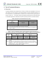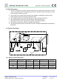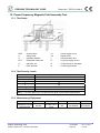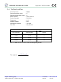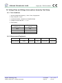
1
CERPASS TECHNOLOGY CORP. Report No.: TECE1211068-A EMC TEST REPORT According to EN 55022:2010 (Class B) AS/ NZS CISPR22:2009 (Class B) EN 61000-3-2:2006+A1:2009+A2:2009 EN 61000-3-3:2008 EN 55024:2010 IEC 61000-4-2:2008 IEC 61000-4-3:2006+A1:2007+A2:2010 IEC 61000-4-4:2004+A1:2010 IEC 61000-4-5:2005 IEC 61000-4-6:2008 IEC 61000-4-8:2009 IEC 61000-4-11:2004 Applicant : VIVOTEK INC. Address : 6F, No.192, Lien-Cheng Rd., Chung-Ho, New Taipei City, 235, Taiwan, R.O.C. Equipment : Network Video Recorder Model No. : ND8401 Trade Name : VIVOTEK The test result refers exclusively to the test presented test model / sample. Without written approval of Cerpass Technology Corp. the test report shall not be reproduced except in full. This test report is only applicable to European Community. Cerpass Technology Corp. Issued Date : Jun. 11, 2013 Tel:886-2-2655-8100 Fax:886-2-2655-8200 Page No. : 1 of 56 CERPASS TECHNOLOGY CORP. Report No.: TECE1211068-A Contents CERTIFICATE OF COMPLIANCE ...................................................................................................................... 5 1. Summary of Test Procedure and Test Results ......................................................................................... 6 2. Immunity Testing Performance Criteria Definition .................................................................................. 6 3. Test Configuration of Equipment under Test ........................................................................................... 7 3.1. Feature of Equipment under Test ..................................................................................................... 7 3.2. Test Manner ..................................................................................................................................... 7 3.3. Description of Support Unit .............................................................................................................. 8 3.4. General Information of Test .............................................................................................................. 9 3.5. Measurement Uncertainty ................................................................................................................ 9 4. Test of Conducted Emission .................................................................................................................... 10 4.1. Test Limit ........................................................................................................................................ 10 4.2. Test Procedures ............................................................................................................................. 11 4.3. Typical Test Setup .......................................................................................................................... 11 4.4. Measurement Equipment ............................................................................................................... 11 4.5. Test Result and Data ...................................................................................................................... 12 4.6. Test Photographs of Power Port .................................................................................................... 17 4.7. Test Photographs of Telecommunication Port................................................................................ 18 5. Test of Radiated Emission ....................................................................................................................... 19 5.1. Test Limit ........................................................................................................................................ 19 5.2. Test Procedures ............................................................................................................................. 20 5.3. Typical Test Setup .......................................................................................................................... 21 5.4. Measurement Equipment ............................................................................................................... 21 5.5. Test Result and Data (30MHz ~ 1GHz).......................................................................................... 22 5.6. Test Result and Data (1GHz ~ 6GHz) ............................................................................................ 26 5.7. Test Photographs (30MHz~1GHz) ................................................................................................. 28 5.8. Test Photographs (1GHz~6GHz) ................................................................................................... 29 6. Harmonics Test ......................................................................................................................................... 30 6.1. Limits of Harmonics Current Measurement ................................................................................... 30 6.2. Test Result and Data ...................................................................................................................... 30 7. Voltage Fluctuations Test ......................................................................................................................... 31 7.1. Test Procedure ............................................................................................................................... 31 7.2. Measurement Equipment ............................................................................................................... 31 7.3. Test Result and Data ...................................................................................................................... 32 7.4. Test Photographs ........................................................................................................................... 33 8. Electrostatic Discharge Immunity Test ................................................................................................... 34 8.1. Test Procedure ............................................................................................................................... 34 8.2. Test Setup for Tests Performed in Laboratory................................................................................ 35 8.3. Test Severity Levels ....................................................................................................................... 36 8.4. Measurement Equipment ............................................................................................................... 36 8.5. Test Result and Data ...................................................................................................................... 37 8.6. Test Photographs ........................................................................................................................... 38 9. Radio Frequency electromagnetic field immunity test ......................................................................... 39 9.1. Test Procedure ............................................................................................................................... 39 Cerpass Technology Corp. Issued Date : Jun. 11, 2013 Tel:886-2-2655-8100 Fax:886-2-2655-8200 Page No. : 2 of 56 CERPASS TECHNOLOGY CORP. Report No.: TECE1211068-A 9.2. Test Severity Levels ....................................................................................................................... 39 9.3. Measurement Equipment ............................................................................................................... 39 9.4. Test Result and Data ...................................................................................................................... 40 9.5. Test Photographs ........................................................................................................................... 41 10. Electrical Fast Transient/ Burst Immunity Test ...................................................................................... 42 10.1. Test Procedure ............................................................................................................................... 42 10.2. Test Severity Levels ....................................................................................................................... 42 10.3. Measurement Equipment ............................................................................................................... 42 10.4. Test Result and Data ...................................................................................................................... 43 10.5. Test Photographs ........................................................................................................................... 44 11. Surge Immunity Test ................................................................................................................................. 45 11.1. Test Procedure ............................................................................................................................... 45 11.2. Test Severity Level ......................................................................................................................... 45 11.3. Measurement Equipment ............................................................................................................... 46 11.4. Test Result and Data ...................................................................................................................... 46 11.5. Test Photographs ........................................................................................................................... 47 12. Conduction Disturbances induced by Radio-Frequency Fields .......................................................... 48 12.1. Test Procedure ............................................................................................................................... 48 12.2. Test Severity Levels ....................................................................................................................... 48 12.3. Measurement Equipment ............................................................................................................... 48 12.4. Test Result and Data ...................................................................................................................... 49 12.5. Test Photographs ........................................................................................................................... 50 13. Power Frequency Magnetic Field Immunity Test ................................................................................... 51 13.1. Test Setup ...................................................................................................................................... 51 13.2. Test Severity Levels ....................................................................................................................... 51 13.3. Measurement Equipment ............................................................................................................... 51 13.4. Test Result and Data ...................................................................................................................... 52 13.5. Test Photographs ........................................................................................................................... 53 14. Voltage Dips and Voltage Interruptions Immunity Test Setup .............................................................. 54 14.1. Test Conditions............................................................................................................................... 54 14.2. Measurement Equipment ............................................................................................................... 54 14.3. Test Result and Data ...................................................................................................................... 55 14.4. Test Photographs ........................................................................................................................... 56 Appendix A. Photographs of EUT………………………….……..…..……..…..…………….….….....A1 ~ A13 Cerpass Technology Corp. Issued Date : Jun. 11, 2013 Tel:886-2-2655-8100 Fax:886-2-2655-8200 Page No. : 3 of 56 CERPASS TECHNOLOGY CORP. Report No.: TECE1211068-A History of this test report ORIGINAL. Additional attachment as following record: Attachment No. Issue Date Description TECE1211068 Nov. 19, 2012 Original TECE1211068-A Jun. 11, 2013 Replace another new one SATA board. Cerpass Technology Corp. Issued Date : Jun. 11, 2013 Tel:886-2-2655-8100 Fax:886-2-2655-8200 Page No. : 4 of 56 CERPASS TECHNOLOGY CORP. Report No.: TECE1211068-A CERTIFICATE OF COMPLIANCE According to EN 55022:2010 (Class B) AS/ NZS CISPR22:2009 (Class B) EN 61000-3-2:2006+A1:2009+A2:2009 EN 61000-3-3:2008 EN 55024:2010 IEC 61000-4-2:2008 IEC 61000-4-3:2006+A1:2007+A2:2010 IEC 61000-4-4:2004+A1:2010 IEC 61000-4-5:2005 IEC 61000-4-6:2008 IEC 61000-4-8:2009 IEC 61000-4-11:2004 Applicant : VIVOTEK INC. Address : 6F, No.192, Lien-Cheng Rd., Chung-Ho, New Taipei City, 235, Taiwan, R.O.C. Equipment : Network Video Recorder Model No. : ND8401 I HEREBY CERTIFY THAT : The measurements shown in this test report were made in accordance with the procedures given in EUROPEAN COUNCIL DIRECTIVE 2004/108/EC. The test was carried out on Nov. 14, 2012 at Cerpass Technology Corp. Signature Hill Chen EMC/RF B.U. Assistant Manager Cerpass Technology Corp. Issued Date : Jun. 11, 2013 Tel:886-2-2655-8100 Fax:886-2-2655-8200 Page No. : 5 of 56 CERPASS TECHNOLOGY CORP. Report No.: TECE1211068-A 1. Summary of Test Procedure and Test Results Test Item Normative References Test Result EN 55022:2010, Conducted Emission PASS AS/ NZS CISPR22:2009 EN 55022:2010, Radiated Emission PASS AS/ NZS CISPR22:2009 Harmonics EN 61000-3-2:2006+A1:2009+A2:2009 PASS Voltage Fluctuations EN 61000-3-3:2008 PASS IEC 61000-4-2:2008 PASS IEC 61000-4-3:2006+A1:2007+A2:2010 PASS IEC 61000-4-4:2004+A1:2010 PASS IEC 61000-4-5:2005 PASS IEC 61000-4-6:2008 PASS IEC 61000-4-8:2009 PASS IEC 61000-4-11:2004 PASS Electrostatic Discharge Immunity Test (ESD) Radio Frequency electromagnetic field immunity test (RS) Electrical Fast Transient/ Burst Immunity Test (EFT) Surge Immunity Test Conduction Disturbances induced by Radio-Frequency Fields Power Frequency Magnetic Field Immunity Test Voltage Dips and Voltage Interruptions Immunity Test 2. Immunity Testing Performance Criteria Definition A. Normal performance within limits specified by the manufacture, requestor or purchaser. B. Temporary loss of function or degradation of performance which ceases after the disturbance ceases, and from which the equipment under test recovers its normal performance, without operator intervention. C. Temporary loss of function or degradation of performance, the correction of which requires operation intervention. D. Loss of function or degradation of performance which is not recoverable, owing to damage to hardware or software, or loss of data. Cerpass Technology Corp. Issued Date : Jun. 11, 2013 Tel:886-2-2655-8100 Fax:886-2-2655-8200 Page No. : 6 of 56 CERPASS TECHNOLOGY CORP. Report No.: TECE1211068-A 3. Test Configuration of Equipment under Test 3.1. Feature of Equipment under Test Please refer to user’s manual. 3.2. Test Manner a. During testing, the interface cables and equipment positions were varied according to Europe Standard EN55022 Class B. b. The complete test system included remote workstation, Monitor, Keyboard, Mouse, Modem, iPod Nano, Earphone, Walk Man, eSATA HDD and EUT for EMI test. The remote workstation included Notebook. c. The complete test system included remote workstation, Monitor, Keyboard, Mouse, Modem, iPod Nano, Flash Memory, Earphone, Walk Man, eSATA HDD and EUT for EMS test. The remote workstation included Notebook. d. The test modes of EMI test as follow: Test Mode 1. VGA 2048 x 1536, LAN: 1Gbps Test Mode 2. VGA 1920 x 1440, LAN: 1Gbps Test Mode 3. VGA 640 x 480, LAN: 1Gbps For conduction test, caused “Test Mode 3” generated the worst test result, it was reported as final data. For radiation test, caused “Test Mode 1” generated the worst test result, it was reported as final data. e. The test modes of disturbances at telecommunication ports test as follow: Test Mode 1. VGA 2048 x 1536, ISN LAN 1 (1Gbps) Test Mode 2. VGA 2048 x 1536, ISN LAN 2 (1Gbps) Test Mode 3. VGA 1920 x 1440, ISN LAN 2 (1Gbps) Test Mode 4. VGA 640 x 480, ISN LAN 2 (1Gbps) Test Mode 5. VGA 2048 x 1536, ISN LAN 2 (100Mbps) Test Mode 6. VGA 2048 x 1536, ISN LAN 2 (10Mbps) caused “Test Mode 2” & “Test Mode 5 ~ Test Mode 6” generated the worst test result, they were reported as final data. f. An executive program, “WINFCC.EXE” under NVR System, which generates a complete line of continuously repeating “H” pattern was used as the test software. The program was executed as follows: 1. Turn on the power of all equipment. 2. The PC reads the test program from the hard disk drive and runs it. 3. The PC sends “H” messages to the EUT, and the EUT displays “H” patterns on the screen. 4. The PC sends “H” messages to the internal Hard Disk, and the Hard Disk reads and writes the message. 5. The PC sends “H“ messages to the modem. 6. Repeat the steps from 2 to 5. g. An executive program, “COLOR BAR.EXE” under NVR System was executed to play 1kHz audio. h. An executive program, “PING.EXE” under NVR System was executed to transmit and receive data to the remote workstation through LAN. i. An executive program, “x.bat” under NVR System was executed to read and write data from iPod Nano and eSATA HDD. j. During the disturbances at telecommunication port test, the condition of LAN utilization in excess of 10%. Cerpass Technology Corp. Issued Date : Jun. 11, 2013 Tel:886-2-2655-8100 Fax:886-2-2655-8200 Page No. : 7 of 56 CERPASS TECHNOLOGY CORP. Report No.: TECE1211068-A 3.3. Description of Support Unit EMI Device Manufacturer Model No. Monitor PHILIPS 202P73 Keyboard DELL SK-8175 Description Power Cable, Unshielding 1.8m VGA Cable, Shielding 1.8m USB Cable, Shielding 1.85m Mouse DELL MOC5UO USB Cable, Shielding 1.85m Modem ACEXX DM-1414 RS232 Cable, Shielding 1.5m iPod Nano*4 APPLE A1320 USB Cable, Shielding 1.0m Earphone MIC MIC-4 Audio Cable, Unshielding 1.35m Walk Man Panasonic RQ-L8LT Audio Cable, Unshielding 1.35m eSATA HDD WD MY Book 2TB eSATA Cable, Shielding 1.0m VPCEB25FW Power Cable, Unshielding 1.8m Remote workstation Notebook*2 SONY Use Cable: Cable Quantity RJ45 2 Description Unshielding, 15.0m EMS Device Manufacturer Model No. Monitor acer MT190WL Keyboard DELL SK-8175 Description Power Cable, Unshielding 1.8m VGA Cable, Shielding 1.8m USB Cable, Shielding 1.85m Mouse DELL MOC5UO USB Cable, Shielding 1.85m Modem ACEXX DM-1414 RS232 Cable, Shielding 1.5m iPod Nano*2 APPLE A1320 USB Cable, Shielding 1.0m Earphone MIC MIC-4 Audio Cable, Unshielding 1.35m Walk Man Panasonic RQ-L8LT Audio Cable, Unshielding 1.35m eSATA HDD WD MY Book 2TB eSATA Cable, Shielding 1.0m Flash Memory*2 TranScend JF150 2GB N/A PSA50T-05M00C Power Cable, Unshielding 1.8m Remote workstation Notebook*2 TOSHIBA Use Cable: Cable Quantity RJ45 2 Description Unshielding, 15.0m Cerpass Technology Corp. Issued Date : Jun. 11, 2013 Tel:886-2-2655-8100 Fax:886-2-2655-8200 Page No. : 8 of 56 CERPASS TECHNOLOGY CORP. Report No.: TECE1211068-A 3.4. General Information of Test Test Site Location (OATS2-SD) : Cerpass Technology Corp. 2F-11, No. 3, Yuan Qu St., (Nankang Software Park), Taipei, Taiwan 115, R.O.C. No.68-1, Shihbachongsi, Shihding Township, Taipei City 223, Taiwan, R.O.C. FCC Registration Number : TW1049, TW1061, 488071, 390316 IC Registration Number : 4934B-1, 4934D-1 VCCI Registration Number : T-1173 for Telecommunication Test C-4139 for Conducted emission test R-3428 for Radiated emission test G-97 for radiated disturbance above 1GHz Frequency Range Investigated : Conducted Emission Test: from 150 kHz to 30 MHz Radiated Emission Test: from 30 MHz to 6,000 MHz Test Distance : The test distance of radiated emission below 1GHz from antenna to EUT is 10 M. The test distance of radiated emission above 1GHz from antenna to EUT is 3 M. Test Site : Laboratory Accreditation 3.5. Measurement Uncertainty Measurement Item Measurement Frequency Polarization Uncertainty Conducted Emission 9 kHz ~ 30 MHz LINE / NEUTRAL 3.25 dB 30 MHz ~ 1,000 MHz Vertical / Horizontal 3.93 dB 1,000 MHz ~ 18,000 MHz Vertical / Horizontal 5.18 dB Radiated Emission Cerpass Technology Corp. Issued Date : Jun. 11, 2013 Tel:886-2-2655-8100 Fax:886-2-2655-8200 Page No. : 9 of 56 CERPASS TECHNOLOGY CORP. Report No.: TECE1211068-A 4. Test of Conducted Emission 4.1. Test Limit Conducted Emissions were measured from 150 kHz to 30 MHz with a bandwidth of 9 kHz and return leads of the EUT according to the methods defined in European Standard EN 55022. The EUT was placed on a nonmetallic stand in a shielded room 0.8 meters above the ground plane as shown in section 4.2. The interface cables and equipment positioning were varied within limits of reasonable applications to determine the position producing maximum conducted emissions. Table 1 Class B Line Conducted Emission Limits: Limits (dB µ V) Frequency range (MHz) Quasi Peak Average 0.15 to 0.50 66 to 56 56 to 46 0.50 to 5 56 46 5. to 30. 60 50 Note 1: The lower limits shall apply at the transition frequencies. Note 2:The limit decreases linearly with the logarithm of the frequency in the range 0.15 MHz to .50MHz. Table 2 - Limits of conducted common mode (asymmetric mode) disturbance at telecommunication ports in the frequency range 0.15 MHz to 30 MHz for class B equipment. Frequency range (MHz) 0.15 to 0.5 0.5 to 30 Voltage limits dB(μV) Quasi-peak Average 84 to 74 74 to 64 74 64 Current limits dB(μA) Quasi-peak Average 40 to 30 30 to 20 30 20 Note 1: The limits decrease linearly with the logarithm of the frequency in the range 0.15 to 0.5 MHz. Note 2: The current and voltage disturbance limits are derived for use with an impedance stabilization network (ISN) which presents a common mode (asymmetric mode) impedance of 150Ω to the telecommunication under test (conversion factor is 20 log10 150/1 = 44dB). Cerpass Technology Corp. Issued Date : Jun. 11, 2013 Tel:886-2-2655-8100 Fax:886-2-2655-8200 Page No. : 10 of 56 CERPASS TECHNOLOGY CORP. Report No.: TECE1211068-A 4.2. Test Procedures a. The EUT was placed on a desk 0.8 meters height from the metal ground plane and 0.4 meter from the conducting wall of the shielding room and it was kept at least 0.8 meters from any other grounded conducting surface. b. Connect EUT to the power mains through a line impedance stabilization network (LISN). c. All the support units are connecting to the other LISN. d. The LISN provides 50 ohm coupling impedance for the measuring instrument. e. The CISPR states that a 50 ohm, 50 micro-Henry LISN should be used. f. Both sides of AC line were checked for maximum conducted interference. g. The frequency range from 150 kHz to 30 MHz was searched h. Set the test-receiver system to Peak Detect Function and Specified Bandwidth with Maximum Hold Mode. 4.3. Typical Test Setup 10cm EUT 80cm 80cm AE 80cm 40cm LISN ISN LISN 40cm 4.4. Measurement Equipment Instrument Manufacturer Model No. Serial No. Calibration Date Valid Date EMI Receiver R&S ESCI 100443 2012/01/12 2013/01/11 LISN Schwarzbeck NSLK 8127 8127-516 2012/03/08 2013/03/07 LISN Schwarzbeck NSLK 8127 8127-568 2012/08/22 2013/08/21 ISN TESEQ GMBH ISN T8 24315 2012/09/28 2013/09/27 Cerpass Technology Corp. Issued Date : Jun. 11, 2013 Tel:886-2-2655-8100 Fax:886-2-2655-8200 Page No. : 11 of 56 CERPASS TECHNOLOGY CORP. Report No.: TECE1211068-A 4.5. Test Result and Data 4.5.1 Conducted Emission for Power Port Test Data Power : AC 230V Pol/Phase : LINE Test Mode 3 : VGA 640 x 480, LAN: 1Gbps Temperature : 23 °C Test Date : Nov. 13, 2012 Humidity : 66 % Note: Level = Reading + Factor Margin = Level – Limit Cerpass Technology Corp. Issued Date : Jun. 11, 2013 Tel:886-2-2655-8100 Fax:886-2-2655-8200 Page No. : 12 of 56 CERPASS TECHNOLOGY CORP. Report No.: TECE1211068-A Power : AC 230V Pol/Phase : NEUTRAL Test Mode 3 : VGA 640 x 480, LAN: 1Gbps Temperature : 23 °C Test Date : Nov. 13, 2012 Humidity : 66 % Note: Level = Reading + Factor Margin = Level – Limit Cerpass Technology Corp. Issued Date : Jun. 11, 2013 Tel:886-2-2655-8100 Fax:886-2-2655-8200 Page No. : 13 of 56 CERPASS TECHNOLOGY CORP. Report No.: TECE1211068-A 4.5.2 Conducted Emission for Telecommunication Port Test Data Power : AC 230V Temperature : 22 °C Test Mode 2 : VGA 2048 x 1536, ISN LAN 2 (1Gbps) Humidity : 56 % Test Date : Nov. 13, 2012 Note: Level = Reading + Factor Margin = Level – Limit Cerpass Technology Corp. Issued Date : Jun. 11, 2013 Tel:886-2-2655-8100 Fax:886-2-2655-8200 Page No. : 14 of 56 CERPASS TECHNOLOGY CORP. Report No.: TECE1211068-A Power : AC 230V Temperature : 22 °C Test Mode 5 : VGA 2048 x 1536, ISN LAN 2 (100Mbps) Humidity : 56 % Test Date : Nov. 13, 2012 Note: Level = Reading + Factor Margin = Level – Limit Cerpass Technology Corp. Issued Date : Jun. 11, 2013 Tel:886-2-2655-8100 Fax:886-2-2655-8200 Page No. : 15 of 56 CERPASS TECHNOLOGY CORP. Report No.: TECE1211068-A Power : AC 230V Temperature : 22 °C Test Mode 6 : VGA 2048 x 1536, ISN LAN 2 (10Mbps) Humidity : 56 % Test Date : Nov. 13, 2012 Note: Level = Reading + Factor Margin = Level – Limit Test engineer: Cerpass Technology Corp. Issued Date : Jun. 11, 2013 Tel:886-2-2655-8100 Fax:886-2-2655-8200 Page No. : 16 of 56 CERPASS TECHNOLOGY CORP. Report No.: TECE1211068-A 4.6. Test Photographs of Power Port Front View Rear View Cerpass Technology Corp. Issued Date : Jun. 11, 2013 Tel:886-2-2655-8100 Fax:886-2-2655-8200 Page No. : 17 of 56 CERPASS TECHNOLOGY CORP. Report No.: TECE1211068-A 4.7. Test Photographs of Telecommunication Port Rear View Cerpass Technology Corp. Issued Date : Jun. 11, 2013 Tel:886-2-2655-8100 Fax:886-2-2655-8200 Page No. : 18 of 56 CERPASS TECHNOLOGY CORP. Report No.: TECE1211068-A 5. Test of Radiated Emission 5.1. Test Limit The EUT shall meet the limits of below Table when measured at the measuring distance R in accordance with the methods described in European Standard EN 55022 Clause 10. If the reading on the measuring receiver shows fluctuations close to the limit, the reading shall be observed for at least 15 s at each measurement frequency; the highest reading shall be recorded, with the exception of any brief isolated high reading, which shall be ignored. Table – Limits for radiated disturbance of class B ITE at a measuring distance of 10 m Frequency range Quasi-peak limits MHz dB(μV/m) 30 to 230 30 230 to 1000 37 NOTE 1 The lower limit shall apply at the transition frequency. NOTE 2 Additional provisions may be required for cases where interference occurs. The EUT shall meet the limits of below Table when measured in accordance with the method described in European Standard EN 55022 Clause 10 and the conditional testing procedure described below. Table – Limits for radiated disturbance of class B ITE at a measuring distance of 3 m Frequency range Average limit GHz dB(μV/m) 1 to 3 50 3 to 6 54 NOTE The lower limit applies at the transition frequency. • Peak limits dB(μV/m) 70 74 Conditional testing procedure: The highest internal source of an EUT is defined as the highest frequency generated or used within the EUT or on which the EUT operates or tunes. If the highest frequency of the internal sources of the EUT is less than 108 MHz, the measurement shall only be made up to 1 GHz. If the highest frequency of the internal sources of the EUT is between 108 MHz and 500 MHz, the measurement shall only be made up to 2 GHz. If the highest frequency of the internal sources of the EUT is between 500 MHz and 1 GHz, the measurement shall only be made up to 5 GHz. If the highest frequency of the internal sources of the EUT is above 1 GHz, the measurement shall be made up to 5 times the highest frequency or 6 GHz, whichever is less. Cerpass Technology Corp. Issued Date : Jun. 11, 2013 Tel:886-2-2655-8100 Fax:886-2-2655-8200 Page No. : 19 of 56 CERPASS TECHNOLOGY CORP. Report No.: TECE1211068-A 5.2. Test Procedures a. The EUT was placed on a rotatable table top 0.8 meter above ground. b. The EUT was set 3/10 meters from the interference receiving antenna which was mounted on the top of a variable height antenna tower. c. The table was rotated 360 degrees to determine the position of the highest radiation. d. The antenna is a half wave dipole and its height is varied between one meter and four meters above ground to find the maximum value of the field strength both horizontal polarization and vertical polarization of the antenna are set to make the measurement. e. For each suspected emission the EUT was arranged to its worst case and then tune the antenna tower (from 1 M to 4 M) and turn table (from 0 degree to 360 degrees) to find the maximum reading. f. Set the test-receiver system to Peak Detect Function and specified bandwidth with Maximum Hold Mode. g. If the emission level of the EUT in peak mode was 3 dB lower than the limit specified, then testing will be stopped and peak values of EUT will be reported, otherwise, the emissions which do not have 3 dB margin will be repeated one by one using the quasi-peak method and reported. Cerpass Technology Corp. Issued Date : Jun. 11, 2013 Tel:886-2-2655-8100 Fax:886-2-2655-8200 Page No. : 20 of 56 CERPASS TECHNOLOGY CORP. Report No.: TECE1211068-A 5.3. Typical Test Setup Below 1GHz Test Setup Antenna Equipment under Test * 10m Turn Table 0.8M Ground Plane Receiver Above 1GHz Test Setup 5.4. Measurement Equipment Instrument Manufacturer Model No. Serial No. Calibration Date Valid Date Bilog Antenna Schaffner CBL6112B 2840 2012/03/23 2013/03/22 Amplifier Agilent 2013/03/20 HP 2944A10593 3807A00454/ 3704A00386 2012/03/21 EMI Receiver 8447D 8546A/ 85460A 2012/08/22 2013/08/21 Spectrum Analyzer R&S FSP40 100047 2012/03/01 2013/02/28 Horn Antenna EMCO 3115 31589 2012/03/01 2013/02/28 Preamplifier Agilent 8449B 3008A01954 2012/02/29 2013/02/28 Cerpass Technology Corp. Issued Date : Jun. 11, 2013 Tel:886-2-2655-8100 Fax:886-2-2655-8200 Page No. : 21 of 56 CERPASS TECHNOLOGY CORP. Report No.: TECE1211068-A 5.5. Test Result and Data (30MHz ~ 1GHz) Power : AC 230V Pol/Phase : VERTICAL Test Mode 1 : VGA 2048 x 1536, LAN: 1Gbps Temperature : 24 °C Test Date : Nov. 13, 2012 Humidity : 59 % Note: Level = Reading + Factor Margin = Level – Limit Cerpass Technology Corp. Issued Date : Jun. 11, 2013 Tel:886-2-2655-8100 Fax:886-2-2655-8200 Page No. : 22 of 56 CERPASS TECHNOLOGY CORP. Report No.: TECE1211068-A Power : AC 230V Pol/Phase : VERTICAL Test Mode 1 : VGA 2048 x 1536, LAN: 1Gbps Temperature : 24 °C Test Date : Nov. 13, 2012 Humidity : 59 % Note: Level = Reading + Factor Margin = Level – Limit Cerpass Technology Corp. Issued Date : Jun. 11, 2013 Tel:886-2-2655-8100 Fax:886-2-2655-8200 Page No. : 23 of 56 CERPASS TECHNOLOGY CORP. Report No.: TECE1211068-A Power : AC 230V Pol/Phase : HORIZONTAL Test Mode 1 : VGA 2048 x 1536, LAN: 1Gbps Temperature : 24 °C Test Date : Nov. 13, 2012 Humidity : 59 % Note: Level = Reading + Factor Margin = Level – Limit Cerpass Technology Corp. Issued Date : Jun. 11, 2013 Tel:886-2-2655-8100 Fax:886-2-2655-8200 Page No. : 24 of 56 CERPASS TECHNOLOGY CORP. Report No.: TECE1211068-A Power : AC 230V Pol/Phase : HORIZONTAL Test Mode 1 : VGA 2048 x 1536, LAN: 1Gbps Temperature : 24 °C Test Date : Nov. 13, 2012 Humidity : 59 % Note: Level = Reading + Factor Margin = Level – Limit Test engineer: Cerpass Technology Corp. Issued Date : Jun. 11, 2013 Tel:886-2-2655-8100 Fax:886-2-2655-8200 Page No. : 25 of 56 CERPASS TECHNOLOGY CORP. Report No.: TECE1211068-A 5.6. Test Result and Data (1GHz ~ 6GHz) Power : AC 230V Pol/Phase : VERTICAL Test Mode 1 : VGA 2048 x 1536, LAN: 1Gbps Temperature : 25 °C Test Date : Nov. 13, 2012 Humidity : 57 % Note: Level = Reading + Factor Margin = Level – Limit Cerpass Technology Corp. Issued Date : Jun. 11, 2013 Tel:886-2-2655-8100 Fax:886-2-2655-8200 Page No. : 26 of 56 CERPASS TECHNOLOGY CORP. Report No.: TECE1211068-A Power Test Mode 1 Test Date Pol/Phase Temperature Humidity : : : AC 230V VGA 2048 x 1536, LAN: 1Gbps Nov. 13, 2012 : : : HORIZONTAL 25 °C 57 % Note: Level = Reading + Factor Margin = Level – Limit Test engineer: Cerpass Technology Corp. Issued Date : Jun. 11, 2013 Tel:886-2-2655-8100 Fax:886-2-2655-8200 Page No. : 27 of 56 CERPASS TECHNOLOGY CORP. Report No.: TECE1211068-A 5.7. Test Photographs (30MHz~1GHz) Front View Rear View Cerpass Technology Corp. Issued Date : Jun. 11, 2013 Tel:886-2-2655-8100 Fax:886-2-2655-8200 Page No. : 28 of 56 CERPASS TECHNOLOGY CORP. Report No.: TECE1211068-A 5.8. Test Photographs (1GHz~6GHz) Front View Rear View Cerpass Technology Corp. Issued Date : Jun. 11, 2013 Tel:886-2-2655-8100 Fax:886-2-2655-8200 Page No. : 29 of 56 CERPASS TECHNOLOGY CORP. Report No.: TECE1211068-A 6. Harmonics Test 6.1. Limits of Harmonics Current Measurement Limits for Class A equipment Harmonics Max. Permissible Order harmonics n current A Odd harmonics 3 2.30 5 1.14 7 0.77 9 0.40 11 0.33 13 0.21 15<=n<=39 0.15¯15/n Even harmonics 2 1.08 4 0.43 6 0.30 8<=n<=40 0.23¯8/n Harmonics Order n 3 5 7 9 11 13 15<=n<=39 Limits for Class D equipment Max. Permissible Max. Permissible harmonics current per harmonics current watt mA/W A Odd Harmonics only 3.4 2.30 1.9 1.14 1.0 0.77 0.5 0.40 0.35 0.33 0.30 0.21 3.85/n 0.15 x15/n NOTE: 1. 2. Class A and Class D are classified according to item section 5 of EN 61000-3-2:2006+A1:2009+A2:2009. According go section 7 of EN 61000-3-2:2006+A1:2009+A2:2009, the above limits for all equipment except for lighting equipment are for all applications having an active input power > 75 W and no limits apply for equipment with an active input power up to and including 75 W. 6.2. Test Result and Data As specified on clause 7 and figure Z1 of EN 61000-3-2:2009, the limits are not specified for equipment with a rated power of 75W or less. The EUT meets the above condition, so it conforms to EN 61000-3-2. Cerpass Technology Corp. Issued Date : Jun. 11, 2013 Tel:886-2-2655-8100 Fax:886-2-2655-8200 Page No. : 30 of 56 CERPASS TECHNOLOGY CORP. Report No.: TECE1211068-A 7. Voltage Fluctuations Test 7.1. Test Procedure The equipment shall be tested under the conditions of Clause 5. The total impedance of the test circuit, excluding the appliance under test, but including the internal impedance of the supply source, shall be equal to the reference impedance. The stability and tolerance of the reference impedance shall be adequate to ensure that the overall accuracy of ±8% is achieved during the whole assessment procedure. 7.2. Measurement Equipment Instrument Manufacturer Model No. Power & Harmonics Analyzer TTI HA1600 Serial No. Calibration Date 198226 2012/01/16 Valid Date 2013/01/15 Cerpass Technology Corp. Issued Date : Jun. 11, 2013 Tel:886-2-2655-8100 Fax:886-2-2655-8200 Page No. : 31 of 56 CERPASS TECHNOLOGY CORP. Report No.: TECE1211068-A 7.3. Test Result and Data Final Test Result : PASS Basic Standard : EN 61000-3-3 Temperature : 25°C Test Data : Nov. 14, 2012 Relative Humidity : 52 % Test engineer: Cerpass Technology Corp. Issued Date : Jun. 11, 2013 Tel:886-2-2655-8100 Fax:886-2-2655-8200 Page No. : 32 of 56 CERPASS TECHNOLOGY CORP. Report No.: TECE1211068-A 7.4. Test Photographs Cerpass Technology Corp. Issued Date : Jun. 11, 2013 Tel:886-2-2655-8100 Fax:886-2-2655-8200 Page No. : 33 of 56 CERPASS TECHNOLOGY CORP. Report No.: TECE1211068-A 8. Electrostatic Discharge Immunity Test 8.1. Test Procedure a. In the case of air discharge testing the climatic conditions shall be within the following ranges: y ambient temperature: 15℃ to 35℃; y relative humidity : 30% to 60%; y atmospheric pressure : 86 KPa (860 mbar) to 106 KPa (1060 mbar). b. Test programs and software shall be chosen so as to exercise all normal modes of operation of the EUT. The use of special exercising software is encouraged, but permitted only where it can be shown that the EUT is being comprehensively exercised. c. The test voltage shall be increased from the minimum to the selected test severity level, in order to determine any threshold of failure. The final severity level should not exceed the product specification value in order to avoid damage to the equipment. d. The test shall be performed with both air discharge and contact discharge. On reselected points at least 10 single discharges (in the most sensitive polarity) shall be applied on air discharge. On reselected points at least 25 single discharges (in the most sensitive polarity) shall be applied on contact discharge. e. For the time interval between successive single discharges an initial value of one second is recommended. Longer intervals may be necessary to determine whether a system failure has occurred. f. In the case of contact discharges, the tip of the discharge electrode shall touch the EUT before the discharge switch is operated. g. In the case of painted surface covering a conducting substrate, the following procedure shall be adopted : y If the coating is not declared to be an insulating coating by the equipment manufacturer, then the pointed tip of the generator shall penetrate the coating so as to make contact with the conducting substrate. y Coating declared as insulating by the manufacturer shall only be submitted to the air discharge. y The contact discharge test shall not be applied to such surfaces. h. In the case of air discharges, the round discharge tip of the discharge electrode shall be approached as fast as possible (without causing mechanical damage) to touch the EUT . After each discharge, the ESD generator (discharge electrode) shall be removed from the EUT. The generator is then retriggered for a new single discharge. This procedure shall be repeated until the discharges are completed. In the case of an air discharge test, the discharge switch, which is used for contact discharge, shall be closed. Cerpass Technology Corp. Issued Date : Jun. 11, 2013 Tel:886-2-2655-8100 Fax:886-2-2655-8200 Page No. : 34 of 56 CERPASS TECHNOLOGY CORP. Report No.: TECE1211068-A 8.2. Test Setup for Tests Performed in Laboratory VCP: 0.5x0.5 m Table Size 1.6LX0.8WX0.8H m 470K ohm EUT 10cm 470K ohm 10cm 470K ohm HCP 1.6mx0.8m 470K ohm GRP The test setup consists of the test generator, EUT and auxiliary instrumentation necessary to perform DIRECT and INDIRECT application of discharges to the EUT as applicable, in the follow manner : a. Contact Discharge to the conductive surfaces and to coupling plane; b. Air Discharge at insulating surfaces. The preferred test method is that of type tests performed in laboratories and the only accepted method of demonstrating conformance with this standard. The EUT was arranged as closely as possible to arrangement in final installed conditions. A ground reference plane was provided on the floor of the test site. It was a metallic sheet (copper or aluminum) of 0.25 mm, minimum thickness; other metallic may be used but they shall have at least 0.65 mm thickness. In the Cerpass Technology Corp., we provided 1 mm thickness stainless steel ground reference plane. The minimum size of the ground reference plane is 2.5 m x 2.5 m, the exact size depending on the dimensions of the EUT. It was connected to the protective grounding system. The EUT was arranged and connected according to its functional requirements. A distance of 1m minimum was provided between the EUT and the wall of the lab. and any other metallic structure. In cases where this length exceeds the length necessary to apply the discharges to the selected points, the excess length shall, where possible, be placed non-inductively off the ground reference plane and shall not come closer than 0.2m to other conductive parts in the test setup. Where the EUT is installed on a metal table, the table was connected to the reference plane via a cable with a 470k ohm resister located at each end, to prevent a build-up of charge. The test setup was consist a wooden table, 0.8m high, standing on the ground reference plane. A HCP, 1.6 m x 0.8 m, was placed on the table. The EUT and cables was isolated from the HCP by an insulating support 0.5 mm thick. The VCP size, 0.5 m x 0.5 m. Cerpass Technology Corp. Issued Date : Jun. 11, 2013 Tel:886-2-2655-8100 Fax:886-2-2655-8200 Page No. : 35 of 56 CERPASS TECHNOLOGY CORP. Report No.: TECE1211068-A 8.3. Test Severity Levels Contact Discharge Level Air Discharge Test Voltage (KV) of Level Contact discharge Test Voltage (KV) of Air Discharge 1 ±2 1 ±2 2 ±4 2 ±4 3 ±6 3 ±8 4 ±8 4 ±15 X Specified X Specified Remark: “X” is an open level. 8.4. Measurement Equipment Instrument Manufacturer Model No. Serial No. Calibration Date Valid Date ESD SIMULATOR Schaffner NSG438 878 2012/03/22 2013/03/21 Cerpass Technology Corp. Issued Date : Jun. 11, 2013 Tel:886-2-2655-8100 Fax:886-2-2655-8200 Page No. : 36 of 56 CERPASS TECHNOLOGY CORP. Report No.: TECE1211068-A 8.5. Test Result and Data Final Test Result : PASS Pass performance criteria : A Required performance criteria : B Basic Standard : IEC 61000-4-2 Product Standard : EN 55024 Test Voltage : Temperature : 23°C Relative Humidity : 56 % Atmospheric Pressure : 1011 hPa Test Date : Sep. 20, 2012 ±2 / ±4 / ±8 KV for air discharge, ±2 / ±4 KV for contact discharge Contact Discharge 25 Voltage Air Discharge times / each 2 KV 10 4 KV times / each 2 KV 4 KV 8 KV Point\Polarity + - + - + - + - + - HCP A A A A --- --- --- --- --- --- VCP A A A A --- --- --- --- --- --- Case A A A A --- --- --- --- --- --- Screw A A A A --- --- --- --- --- --- Button --- --- --- --- A A A A A A RJ45 A A A A --- --- --- --- --- --- USB Port --- --- --- --- A A A A A A RS232 Port --- --- --- --- A A A A A A VGA Port --- --- --- --- A A A A A A Audio Port --- --- --- --- A A A A A A eSATA Port --- --- --- --- A A A A A A Note: ” A” means the EUT function is normal working during the test. Test engineer: Cerpass Technology Corp. Issued Date : Jun. 11, 2013 Tel:886-2-2655-8100 Fax:886-2-2655-8200 Page No. : 37 of 56 CERPASS TECHNOLOGY CORP. Report No.: TECE1211068-A 8.6. Test Photographs Cerpass Technology Corp. Issued Date : Jun. 11, 2013 Tel:886-2-2655-8100 Fax:886-2-2655-8200 Page No. : 38 of 56 CERPASS TECHNOLOGY CORP. Report No.: TECE1211068-A 9. Radio Frequency electromagnetic field immunity test 9.1. Test Procedure a. The equipment to be tested is placed in the center of the enclosure on a wooden table. The equipment is then connected to power and signal leads according to pertinent installation instructions. b. The antenna which is enabling the complete frequency range of 80-1000 MHz is placed 3m away from the equipment. The required field strength is determined by placing the field strength meter(s) on top of or directly alongside the equipment under test and monitoring the field strength meter via a remote field strength indicator outside the enclosure while adjusting the continuous-wave to the applicable antennae. c. The test is normally performed with the antenna facing the most sensitive side of the EUT. The polarization of the field generated by the bucolical antenna necessitates testing each position twice, once with the antenna positioned vertically and again with the antenna positioned horizontally. The circular polarization of the field from the log-spiral antenna makes a change of position of the antenna unnecessary. d. At each of the above conditions, the frequency range is swept 80-1000 MHz, pausing to adjust the R.F. signal level or to switch oscillators and antenna. The rate of sweep is in the order of 1.5*10-3 decades/s. The sensitive frequencies or frequencies of dominant interest may be discretely analyzed. 9.2. Test Severity Levels Level 1 2 3 X Frequency Band : 80-1000 MHz Test field strength (V/m) 1 3 10 Specified Remark: “X” is an open class. 9.3. Measurement Equipment Instrument Manufacturer Model No. Serial No. Calibration Date Valid Date Amplifiers 80-1000MHz/100W SCHAFFNER CBA9413B 43510 N/A N/A Amplifiers 80-3000MHz/20W SCHAFFNER CBA9428 43515 N/A N/A Antenna SCHAFFNER CBL6141A 4257 N/A N/A Power Meter Boonton 4231A-01 115902 2012/09/26 2013/09/25 Field Probe HOLADAY HI-6105 00144727 2012/09/20 2013/09/19 Signal Generator HP 8648B 3629U00612 2012/09/26 2013/09/25 Power Sensor Boonton 51011-EMC 33312 2012/09/26 2013/09/25 Cerpass Technology Corp. Issued Date : Jun. 11, 2013 Tel:886-2-2655-8100 Fax:886-2-2655-8200 Page No. : 39 of 56 CERPASS TECHNOLOGY CORP. Report No.: TECE1211068-A 9.4. Test Result and Data Final Test Result : PASS Pass performance criteria : A Required performance criteria : A Basic Standard : IEC 61000-4-3 Product Standard : EN 55024 Frequency Range : 80~1000 MHz Temperature : 21°C Relative Humidity : 62 % Atmospheric Pressure : 1011 hPa Test Date : Sep. 19, 2012 Modulation : AM 80% , 1KHz sine wave, Dwell time: 2.9 S Frequency Step Size : 1 % of preceding frequency value Frequency (MHz) Antenna Polarization face Field strength (V/m) Result 80~1000 Vertical Front 3 V/m A 80~1000 Vertical Rear 3 V/m A 80~1000 Vertical Left 3 V/m A 80~1000 Vertical Right 3 V/m A 80~1000 Horizontal Front 3 V/m A 80~1000 Horizontal Rear 3 V/m A 80~1000 Horizontal Left 3 V/m A 80~1000 Horizontal Right 3 V/m A Note: “A” means the EUT function is normal working during the test. Test engineer: Cerpass Technology Corp. Issued Date : Jun. 11, 2013 Tel:886-2-2655-8100 Fax:886-2-2655-8200 Page No. : 40 of 56 CERPASS TECHNOLOGY CORP. Report No.: TECE1211068-A 9.5. Test Photographs Cerpass Technology Corp. Issued Date : Jun. 11, 2013 Tel:886-2-2655-8100 Fax:886-2-2655-8200 Page No. : 41 of 56 CERPASS TECHNOLOGY CORP. Report No.: TECE1211068-A 10. Electrical Fast Transient/ Burst Immunity Test 10.1. Test Procedure a. In order to minimize the effect of environmental parameters on test results, the climatic conditions when test is carrying out shall comply with the following requirements: y ambient temperature: 15℃ to 35℃; y relative humidity : 45% to 75%; y Atmospheric pressure: 86 Kpa (860 mbar) to 106 Kpa (1060 mbar). b. In order to minimize the effect of environmental parameters on test results, the electromagnetic environment of the laboratory shall not influence the test results. c. The variety and diversity of equipment and systems to be tested make it difficult to establish general criteria for the evaluation of the effects of fast transients/bursts on equipment and systems. d. Test on Power Line: y The EFT/B-generator was located on the GRP.. The length from the EFT/B-generator to the EUT is not exceeding 1 m. y The EFT/B-generator provides the ability to apply the test voltage in a non-symmetrical condition to the power supply input terminals of the EUT. e. Test on Communication Lines y The coupling clamp is composed of a clamp unit for housing the cable (length more than 3 m), and was placed on the GRP. y The coupling clamp provides the ability of coupling the fast transient/bursts to the cable under test. f. The test results may be classified on the basic of the operating conditions and the functional specification of the equipment under test, according to the following performance criteria : y Normal performance within the specification limits. y Temporary degradation or loss of function or performance which is self-recoverable. y Temporary degradation or loss of function or performance which requires operator intervention or system reset. y Degradation or loss of function which is not recoverable due to damage of equipment (components). 10.2. Test Severity Levels The following test severity levels are recommended for the fast transient/burst test : Level 1 2 3 4 X Open circuit output test voltage ± 10% On Power Supply On I/O signal, data and control line 0.5 KV 0.25 KV 1.0 KV 0.50 KV 2.0 KV 1.00 KV 4.0 KV 2.00 KV Specified Specified Remark : “ X ” is an open level. The level is subject to negotiation between the user and manufacturer or is specified by the manufacturer. 10.3. Measurement Equipment Instrument Manufacturer Model No. Serial No. Calibration Date Valid Date TESQ NSG3060 TESQ NSG3060 1385 2012/07/03 2013/07/02 Cerpass Technology Corp. Issued Date : Jun. 11, 2013 Tel:886-2-2655-8100 Fax:886-2-2655-8200 Page No. : 42 of 56 CERPASS TECHNOLOGY CORP. Report No.: TECE1211068-A 10.4. Test Result and Data Final Test Result : PASS Pass performance criteria : A Required performance criteria : B Basic Standard : IEC 61000-4-4 Product Standard : Temperature EN 55024 On Power Supply -- ±0.5 KV, ±1.0 KV : On Signal Port -- ±0.5 KV : 23°C Relative Humidity : 49 % Atmospheric Pressure : 1011 hPa Test Voltage Test Date : Sep. 12, 2012 Test Mode: The test result of all test modes are the same Pulse : 5/50 ns Repetition Rate: 5 kHz below and equal 2.0 kV Burst : 15m/300ms Test time : 1 min/each condition Voltage/ Mode/ Polarity/ Result/ Phase Power Line Signal Line 0.5 kV 1.0 kV + - + - L A A A A N A A A A L-N A A A A PE A A A A L-PE A A A A N-PE A A A A L-N-PE A A A A RJ45 (10M/100M/1G) A A --- --- Note: “A” Means the EUT function is normal working during the test. Test engineer: Cerpass Technology Corp. Issued Date : Jun. 11, 2013 Tel:886-2-2655-8100 Fax:886-2-2655-8200 Page No. : 43 of 56 CERPASS TECHNOLOGY CORP. Report No.: TECE1211068-A 10.5. Test Photographs Main Clamp Cerpass Technology Corp. Issued Date : Jun. 11, 2013 Tel:886-2-2655-8100 Fax:886-2-2655-8200 Page No. : 44 of 56 CERPASS TECHNOLOGY CORP. Report No.: TECE1211068-A 11. Surge Immunity Test 11.1. Test Procedure a. b. c. d. e. f. g. h. i. Climatic conditions The climatic conditions shall comply with the following requirements : y ambient temperature : 15 ℃ to 35 ℃ y relative humidity : 10 % to 75 % y atmospheric pressure : 86 kPa to 106 kPa ( 860 mbar to 1060 mbar ) Electromagnetic conditions the electromagnetic environment of the laboratory shall not influence the test results. The test shall be performed according the test plan that shall specify the test set-up with y generator and other equipment utilized; y test level ( voltage/current ); y generator source impedance; y internal or external generator trigger; y number of tests : at least five positive and five negative at the selected points; y repetition rate : maximum 1/min. y inputs and outputs to be tested; y representative operating conditions of the EUT; y sequence of application of the surge to the circuit; y phase angle in the case of AC. power supply; y actual installation conditions, for example : AC : neutral earthed, DC : ( + ) or ( - ) earthed to simulated the actual earthing conditions. If not otherwise specified the surges have to be applied synchronized to the voltage phase at the zero-crossing and the peak value of the AC. voltage wave ( positive and negative ). The surges have to be applied line to line and line(s) and earth. When testing line to earth, the test voltage has to be applied successively between each of the lines and earth, if there is no other specification. The test procedure shall also consider the non-linear current-voltage characteristics of the equipment under test. Therefore the test voltage has to be increased by steps up to the test level specified in the product standard or test plan. All lower levels including the selected test level shall be satisfied. For testing the secondary protection, the output voltage of the generator shall be increased up to the worst-case voltage breakdown level ( let-through level ) of the primary protection. If the actual operating signal sources are not available, that may be simulated. Under no circumstances may the test level exceed the product specification. The test shall be carried out according to a test plan. To find all critical points of the duty cycle of the equipment, a sufficient number of positive and negative test pulses shall be applied. For acceptance test previously unstressed equipment shall be used to the protection devices shall be replaced. 11.2. Test Severity Level Level Open-circuit test voltage, ± 10%, KV 1 0.5 2 1.0 3 2.0 4 4.0 X Specified NOTE: “X” is an open class. This level can be specified in the product specification. Cerpass Technology Corp. Issued Date : Jun. 11, 2013 Tel:886-2-2655-8100 Fax:886-2-2655-8200 Page No. : 45 of 56 CERPASS TECHNOLOGY CORP. Report No.: TECE1211068-A 11.3. Measurement Equipment Instrument Manufacturer Model No. Serial No. Calibration Date Valid Date TESQ NSG3060 TESQ NSG3060 1385 2012/07/03 2013/07/02 11.4. Test Result and Data Final Test Result : PASS Pass performance criteria : A Required performance criteria : B Basic Standard : IEC 61000-4-5 Product Standard : EN 55024 Test Voltage : Input AC Power Port -- ± 0.5 kV, ± 1.0 kV, ± 2.0 kV Temperature : 23°C Relative Humidity : 49 % Atmospheric Pressure : 1011 hPa Test Date : Sep. 12, 2012 Test Mode: The test result of all test modes are the same Power Port Waveform : 1.2/50μs(8/20μs) Repetition rate : 60 sec Phase Voltage / Mode / Polarity / Result 0.5 kV, 1.0kV L-N 0.5 kV, 1.0kV, 2.0kV L-PE, N-PE Time : 5 time/each condition 0° 90° 180° 270° + A A A A - A A A A + A A A A - A A A A Note:” A” means the EUT function is normal working during the test. Signal Port RJ45 The ports of EUT which according to the manufacturer’s specification can not connect directly to outdoor. Test engineer: Cerpass Technology Corp. Issued Date : Jun. 11, 2013 Tel:886-2-2655-8100 Fax:886-2-2655-8200 Page No. : 46 of 56 CERPASS TECHNOLOGY CORP. Report No.: TECE1211068-A 11.5. Test Photographs Cerpass Technology Corp. Issued Date : Jun. 11, 2013 Tel:886-2-2655-8100 Fax:886-2-2655-8200 Page No. : 47 of 56 CERPASS TECHNOLOGY CORP. Report No.: TECE1211068-A 12. Conduction Disturbances induced by Radio-Frequency Fields 12.1. Test Procedure a. b. c. d. e. f. g. h. i. j. k. The EUT shall be operated within its intended climatic conditions. The temperature and relative humidity should be recorded. This test method test can be performed without using a sell shielded enclosure. This is because the disturbance levels applied and the geometry of the setups are not likely to radiated a high amount of energy, especially at the lower frequencies. If under certain circumstances the radiated energy is too high, a shielded enclosure has to be used. The test shall be performed with the test generator connected to each of the coupling and decoupling devices in turn while the other non-excited RF-input ports of the coupling devices are terminated by a 50 ohm load resistor. The frequency range is swept from 150 KHz to 80 MHz, using the signal levels established during the setting process, and with the disturbance signal 80% amplitude modulated with a 1KHz sign wave, pausing to adjust the RF-signal level or to switch coupling devices as necessary. The rate of sweep shall no exceed 1.5 x 10⁻³ decades/s. Where the frequency is swept incrementally, the step size shall no exceed 1% of the start and thereafter 1% of the preceding frequency value. The dwell time at each frequency shall not be less than the time necessary for the EUT to be exercised, and able to respond. Sensitive frequencies e.g. clock frequency (ies) and harmonics or frequencies of dominant interest shall be analyzed separately. An alternative test procedure may be adopted, wherein the frequency range is swept incrementally, with a step size not exceeding 4% of the start ad thereafter 4% of the preceding frequency value. The test level should be at least twice the value of the specified test level. In cases of dispute, the test procedure using a step size not exceeding 1% of the start and thereafter 1% of preceding frequency value shall take precedence. Attempts should be made to fully exercise the EUT during testing, and to fully interrogate all exercise modes selected for susceptibility. The use of special exercising programs is recommended. Testing shall be performed according to a Test Plan, which shall be included in the test report. It may be necessary to carry out some investigatory testing in order to establish some aspects of the test plan. 12.2.Test Severity Levels Level Voltage Level ( EMF ) 1 1V 2 3V 3 10 V x Specified NOTE - x is an open class. This level can be specified in the product specification. 12.3. Measurement Equipment Instrument Manufacturer Model No. Serial No. Calibration Date Valid Date CS GENERATOR Schaffner NSG 2070 1059 2012/09/26 2013/09/25 CDN (M2+M3) Schaffner M016 20056 2012/09/26 2013/09/25 CDN Schaffner T400 19818 2012/09/26 2013/09/25 EM-CLAMP Schaffner KEMZ 801 19793 2012/09/26 2013/09/25 Cerpass Technology Corp. Issued Date : Jun. 11, 2013 Tel:886-2-2655-8100 Fax:886-2-2655-8200 Page No. : 48 of 56 CERPASS TECHNOLOGY CORP. Report No.: TECE1211068-A 12.4. Test Result and Data Final Test Result : PASS Pass performance criteria : A Required performance criteria : A Basic Standard : IEC 61000-4-6 Product Standard Temperature : EN 55024 CDN-(M3) for AC power ports : CDN-T400 for Signal Ports EM-CLAMP for Signal Ports : 23°C Relative Humidity : 49 % Atmospheric Pressure : 1011 hPa Coupling mode Test Date : Sep. 12, 2012 Test Mode: The test result of all test modes are the Frequency : 0.15~80MHz, Modulation : AM 80%,1KHz sine wave, Dwell time: 2.9s Frequency Step Size : 1 % of preceding frequency value Frequency Test Mode Voltage(V) Result 0.15 ~ 80MHz Power(M3) 3 A 0.15 ~ 80MHz RJ45 LAN (10M / 100M) 3 A 0.15 ~ 80MHz Clamp (1G) 3 A Note: “A” Means the EUT function is normal working during the test. Test engineer: Cerpass Technology Corp. Issued Date : Jun. 11, 2013 Tel:886-2-2655-8100 Fax:886-2-2655-8200 Page No. : 49 of 56 CERPASS TECHNOLOGY CORP. Report No.: TECE1211068-A 12.5. Test Photographs Cerpass Technology Corp. Issued Date : Jun. 11, 2013 Tel:886-2-2655-8100 Fax:886-2-2655-8200 Page No. : 50 of 56 CERPASS TECHNOLOGY CORP. Report No.: TECE1211068-A 13. Power Frequency Magnetic Field Immunity Test 13.1. Test Setup GPR A S EUT Lc E : : : : : : Ground plane Safety earth Insulating support Equipment under test Induction coil Earth terminal C1 C2 L B D G : : : : : : Power supply circuit Signal circuit Communication line To power supply source To signal source, simulator To the test generator 13.2. Test Severity Levels Level 1 2 3 4 5 X1) Magnetic field strength (A/m) 1 3 10 30 100 special NOTE 1 “X” is an open level. This level can be given in the product specification. 13.3. Measurement Equipment Instrument Manufacturer Model No. MAGNETIC FIELD GENERATOR KeyTek F-1000-4-8-G -125A Serial No. Calibration Date Valid Date N/A 2012/09/26 2013/09/25 Cerpass Technology Corp. Issued Date : Jun. 11, 2013 Tel:886-2-2655-8100 Fax:886-2-2655-8200 Page No. : 51 of 56 CERPASS TECHNOLOGY CORP. Report No.: TECE1211068-A 13.4. Test Result and Data Final Test Result : PASS Pass performance criteria : A Required performance criteria : A Basic Standard : IEC 61000-4-8 Product Standard : EN 55024 Temperature : 21°C Relative Humidity : 62 % Atmospheric Pressure : 1011 hPa Test Date : May 22, 2012 Power Frequency Magnetic Field : 50 Hz, 1 A/m Coil Orientation Testing duration Results X-axis 1.0 Min A Y-axis 1.0 Min A Z-axis 1.0 Min A Note: “A” Mean the EUT function is normal working during the test. Test engineer: Cerpass Technology Corp. Issued Date : Jun. 11, 2013 Tel:886-2-2655-8100 Fax:886-2-2655-8200 Page No. : 52 of 56 CERPASS TECHNOLOGY CORP. Report No.: TECE1211068-A 13.5. Test Photographs Cerpass Technology Corp. Issued Date : Jun. 11, 2013 Tel:886-2-2655-8100 Fax:886-2-2655-8200 Page No. : 53 of 56 CERPASS TECHNOLOGY CORP. Report No.: TECE1211068-A 14. Voltage Dips and Voltage Interruptions Immunity Test Setup 14.1. Test Conditions 1. Source voltage and frequency : 230V / 50Hz, Single phase. 2. Test of interval : 10 sec. 3. Level and duration : Sequence of 3 dips/interrupts. 4. Voltage rise (and fall) time : 1 ∼ 5 μs. 5. Test severity : Voltage dips and Interrupt reduction (%) Test Duration (period) >95% 250 30% 25 >95% 0.5 14.2. Measurement Equipment Instrument Manufacturer Model No. TESQ NSG3060 TESQ NSG3060 Serial No. Calibration Date Valid Date 1385 2012/07/03 2013/07/02 Cerpass Technology Corp. Issued Date : Jun. 11, 2013 Tel:886-2-2655-8100 Fax:886-2-2655-8200 Page No. : 54 of 56 CERPASS TECHNOLOGY CORP. Report No.: TECE1211068-A 14.3. Test Result and Data Final Test Result : PASS Pass performance Criteria : C for voltage interruption, A for voltage dips Required performance Criteria : C for voltage interruption, B/C for voltage dips Basic Standard : IEC 61000-4-11 Product Standard : EN 55024 Temperature : 21°C Relative Humidity : 62 % Atmospheric Pressure : 1011 hPa Test Date : May 22, 2012 Test Mode: The test result of all test modes are the same Voltage(UT): AC 230 V 50 Hz Interval(s) : 10s Times : 3 Test mode Test level reduction % Durations (period) 0° 180° Voltage interruptions >95% 250 C C 30% 25 A A >95% 0.5 A A Phase / Result Voltage dips Note: “A” means the EUT function is normal working during the test. “C “ means the Power of EUT is off during the test, and it can be recover by manual resetting. Test engineer: Cerpass Technology Corp. Issued Date : Jun. 11, 2013 Tel:886-2-2655-8100 Fax:886-2-2655-8200 Page No. : 55 of 56 CERPASS TECHNOLOGY CORP. Report No.: TECE1211068-A 14.4. Test Photographs Cerpass Technology Corp. Issued Date : Jun. 11, 2013 Tel:886-2-2655-8100 Fax:886-2-2655-8200 Page No. : 56 of 56 CERPASS TECHNOLOGY CORP. Report No.: TECE1211068-A Appendix A. Photographs of EUT Cerpass Technology Corp. Issued Date : Jun. 11, 2013 Tel:886-2-2655-8100 Fax:886-2-2655-8200 Page No. : A1 of A13 CERPASS TECHNOLOGY CORP. Report No.: TECE1211068-A Cerpass Technology Corp. Issued Date : Jun. 11, 2013 Tel:886-2-2655-8100 Fax:886-2-2655-8200 Page No. : A2 of A13 CERPASS TECHNOLOGY CORP. Report No.: TECE1211068-A Cerpass Technology Corp. Issued Date : Jun. 11, 2013 Tel:886-2-2655-8100 Fax:886-2-2655-8200 Page No. : A3 of A13 CERPASS TECHNOLOGY CORP. Report No.: TECE1211068-A Cerpass Technology Corp. Issued Date : Jun. 11, 2013 Tel:886-2-2655-8100 Fax:886-2-2655-8200 Page No. : A4 of A13 CERPASS TECHNOLOGY CORP. Report No.: TECE1211068-A Cerpass Technology Corp. Issued Date : Jun. 11, 2013 Tel:886-2-2655-8100 Fax:886-2-2655-8200 Page No. : A5 of A13 CERPASS TECHNOLOGY CORP. Report No.: TECE1211068-A Cerpass Technology Corp. Issued Date : Jun. 11, 2013 Tel:886-2-2655-8100 Fax:886-2-2655-8200 Page No. : A6 of A13 CERPASS TECHNOLOGY CORP. Report No.: TECE1211068-A Cerpass Technology Corp. Issued Date : Jun. 11, 2013 Tel:886-2-2655-8100 Fax:886-2-2655-8200 Page No. : A7 of A13 CERPASS TECHNOLOGY CORP. Report No.: TECE1211068-A Cerpass Technology Corp. Issued Date : Jun. 11, 2013 Tel:886-2-2655-8100 Fax:886-2-2655-8200 Page No. : A8 of A13 CERPASS TECHNOLOGY CORP. Report No.: TECE1211068-A Cerpass Technology Corp. Issued Date : Jun. 11, 2013 Tel:886-2-2655-8100 Fax:886-2-2655-8200 Page No. : A9 of A13 CERPASS TECHNOLOGY CORP. Report No.: TECE1211068-A Cerpass Technology Corp. Issued Date : Jun. 11, 2013 Tel:886-2-2655-8100 Fax:886-2-2655-8200 Page No. : A10 of A13 CERPASS TECHNOLOGY CORP. Report No.: TECE1211068-A Cerpass Technology Corp. Issued Date : Jun. 11, 2013 Tel:886-2-2655-8100 Fax:886-2-2655-8200 Page No. : A11 of A13 CERPASS TECHNOLOGY CORP. Report No.: TECE1211068-A Cerpass Technology Corp. Issued Date : Jun. 11, 2013 Tel:886-2-2655-8100 Fax:886-2-2655-8200 Page No. : A12 of A13 CERPASS TECHNOLOGY CORP. Report No.: TECE1211068-A Cerpass Technology Corp. Issued Date : Jun. 11, 2013 Tel:886-2-2655-8100 Fax:886-2-2655-8200 Page No. : A13 of A13