1
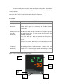
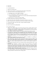
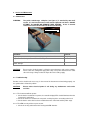
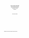
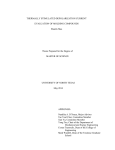
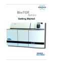
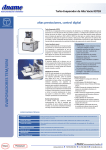
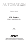
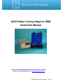
K25X Peltier Cooling Stage for SEM
Instruction Manual
For technical and applications advice plus our on-line shop for
spares and consumable parts visit www.quorumtech.com
A4/515/043 K25 User Manual Issue 12
Quorum Technologies Ltd
South Stour Avenue
Ashford
Kent
TN23 7RS
UK
Email:
Website:
Tel:
+44 (0) 1233 646332
Fax:
+44 (0) 1233 640744
[email protected]
http:///www.quorumtech.com
For further information regarding any of the other products designed and manufactured by Quorum
Technologies, contact your local representative or directly to Quorum Technologies at the address
above.
C E Declaration:
This Equipment of this Design and manufacture and marked CE, conforms to the requirements of
the European Directives EMC 89/336/EEC & LVD 73/23/EEC.
This Equipment will “fail safe” in the presence of excessive RF, Electrostatic Discharge or Mains
Transients. While a loss of function could occur under extreme circumstances the Equipment’s
operation will be fully recoverable under normal operating conditions.
Mains Lead.
This Equipment must be Earthed and fitted with the correct lead for the country of
operation. This will normally be achieved from the correct mains supply socket
Earth Connector.
This Equipment is normally supplied from 3-pin supply including Earth. If there is
only a 2-pin supply is available a separate Earth must be fitted.
The
supplementary Earth stud can be used to facilitate this requirement.
Disclaimer
The components and packages described in this document are mutually compatible and
guaranteed to meet or exceed the published performance specifications. No performance
guarantees, however, can be given in circumstances where these component packages are
used in conjunction with equipment supplied by companies other than Quorum Technologies Ltd.
Quorum Emitech is a wholly owned business of Quorum Technologies Limited. Registered offices Unit 19 Charlwoods
Road, East Grinstead, West Sussex. RH19 2HL. Registered in England and Wales, company No. 4273003.
A4/515/043 K25 User Manual Issue 12
1.
INTRODUCTION
3
2.
SPECIFICATIONS
3
3.
INSTALLATION
4
4.
SERVICE AND MAINTENANCE
7
5.
SPARES AND ACCESSORIES
9
6.
DOCUMENT HISTORY
10
A4/515/043 K25 User Manual Issue 12
1. Introduction
The Emitech K25X is a Peltier Driven Cooling Stage for SEM. It allows the stage to be
cooled to sub zero temperatures for samples, which may be sensitive at ambient temperature,
subject to beam damage, or may sublime at ambient temperatures. The stage may also be heated
for above ambient work.
The Cooling Stage is readily located on the existing SEM stage.
The Cooling Stage on the SEM achieves primary cooling through the function of the peltier,
but has the necessary secondary cooling via a fluid cooling circuit, allowing an externally chilled
supply to be connected to provide the heat transfer away from the peltier stage.
This arrangement allows the majority of the x, y, z and Tilt features to be maintained to an
effective operating level.
A twin channel temperature control system allows the independent control of both a ‘cold
setpoint’ target and a ‘hot setpoint’ target, with the ability of the unit to transit rapidly between these
two set points through the use of a switch mounted on the front panel of the main control box.
The System Consists of: • Peltier cooled stage and secondary cooling circuit.
• Single Vacuum Interface Port with integral electrical connector for peltier supply and temperature
monitoring and twin fluid connectors for cooling circuit supply.
• Control Unit with twin P. I. D. (Proportional, Integral, Derivative) Controllers, with set points control
and input temperature and measured temperature displays.
2. Specifications
o
o
o
o
• Stage Temperature control range. Heating +20 C to +75 C; Cooling 0 C to –30 C. Resolution +/o
1C
• Typical operating temperature -10°C within 1.5 minutes from stand-by condition.
• Control Unit, overall Dimensions 137mm height x 235mm width x 260mm depth complete with a
set of 1metre interconnecting leads, and a mains supply lead.
• Stage Size 24mm x 30mm.
• 20mm X and Y Stage movements permissible
• Tilt normal movement maintained for X Ray analysis (typically to 45 degree)
• Limited Rotate facility depending on SEM.
• Service
– mains power, 240/220v or 120/100v 50/60Hz, Single Phase, 1amp maximum.
– Cooling water (from SEM cooling circuit, stand alone chiller or tap source) Max
Temp +15ºC, Min Temp +5ºC, 20psi maximum pressure, 0.5L minimum flow rate.
• CE Product Conformity
3. Installation
It is important that this equipment is installed and operated by skilled personnel in
accordance with these instructions. Failure to do so may result in damage, and impair
protection provided. 'If in doubt - ask'.
For installation details please refer to the document supplied with the instrument, which will
be particular to the microscope being used. A suitable location on the SEM control console should
utilise. The total weight of the system is approximately 20Kg. The system operating environment
ambient temperature range is 15oC - 25oC in a non-condensing relative humidity of not more than
75%. Sufficient ventilation is required, and positioning should be out of direct sunlight. The system is
rated for continuous operation.
Prior to assembly the integrity of the cooling circuit lines should be tested by connecting the
unit to the proposed cooling source and running the unit whilst still outside the microscope. Any
observed fluid loss and the unit should not be fitted to the microscope. The observations should be
immediately reported to a service engineer.
3.1 Preliminary Checks
Remove Instrument from packing and place in an appropriate operational position. Carry out
visual inspection for any signs of transit damage.
3.2 Connections.
Title
Function
Power In
Main power inlet socket.
Peltier Stage Drive Cable
This is a cable assembly providing power and sensor lines to
the peltier unit itself from the control box, terminated at each
end with 8-pin connectors.
Main Fuse
Electronics power supply fuse.
NOTES
1. Any other items on rear panel not listed are for common manufacturing and are not available for
this Instrument.
2. A single phase AC supply with Earth is required - selected to the correct voltage for the country of
operation i.e. either nominal 230V or nominal 115V. The voltage and frequency ranges are: -
Nominal 230
Max Current 0.5 A
200 - 264V
47Hz To 63Hz
Nominal 115
Max Current 1A
90V - 132V
47Hz To 63Hz
The electrical input to the Instrument is made with the power lead provided. The Instrument
connection is a standard IEC inlet and the lead supplied is fitted with the appropriate plug for the
country of operation.
Ensure the plugs are firmly located. Check the voltage is the correct voltage for the country
of operation, which should correspond to the voltage label on the Instrument.
3.3 Controls
These are the controls by which the instrument is operated.
Controls
Rocker Switch
(Rear Panel)
This switch, mounted at the rear of the instrument within the power inlet
module, applies power to the instrument and depending upon the
position of the front panel lever switch will place the unit in stand-by or
control mode.
Stand-by/ Heat /Cool
lever switch
(Front Panel)
Standby (lever switch central) - Isolates the Pre-cool peltier stage from
any electrical power input. The stage will attain the temperature of the
circulating cooling fluid.
Heat (lever switch up) – Drives the peltier in heat pump mode to
increase the temperature of the stage to the set point temperature
selected.
Cool (lever switch down) - Drives the peltier in cooling mode to decrease
the temperature of the stage to the set point temperature selected.
Temperature
Controllers
(Front Panel)
All operating parameters for the temperature controllers have been
factory set. The only user changeable parameter are the temperature
set-points. This is achieved using the up and down arrow keys as shown
in the Figure 1 on the following page.
Figure 1. Layout of Temperature Controller Features.
Present
Value
Display
Output
LED
Target
Value
Display
Setpoint
Select
Button
Decrease
Setpoint
Button
Increase
Setpoint
Button
3.4 Operation
3.4.1 Operating Sequence
1) Switch on the chilling system.
2) Switch on the instrument in ‘stand-by’ mode (rocker switch to central position).
3) Select the desired hot and cold operating temperatures by: a) Selecting the ‘hot’ or ‘cold’ controller as required
b) Press and hold down the ‘setpoint select’ button (see figure 1.)
c) Press the ‘setpoint increase’ or ‘setpoint decrease’ button until the desired target temperature
is shown in the target value display.
d) Repeat steps a) to c) above for the other controller.
4) Load the sample onto the stage and evacuate the chamber.
5) Select the desired control mode with the front panel lever switch (i.e. heat or cool)
6) When the temperature has stabilised perform the desired operations with the sample.
7) To remove the sample, warm up the stage / sample to ambient temperature.
8) Remove the sample
9) Place the instrument into Stand-by Mode.
3.4.2 Using the instrument
•
•
•
•
•
•
•
•
•
Switch on the cooling supply to the unit and ensure the flow of cooling media has been
established. Ensure the temperature of the media is within the specifications shown in section 2.
Assuming that the instrument is completely installed as described above, place the front panel
lever switch into ‘stand-by’ mode (central position).
Now switch the instrument on at the rear rocker switch contained in the power inlet module.
The temperature controllers will initialise and display the current stage temperature in green on
the upper section of the display. This temperature will reflect the temperature of the cooling
media being passed to the peltier head. The desired temperature in red is shown on the bottom
half of the display. Press the star key in conjunction with the up arrow key or down arrow key to
set the target temperature to the desired working temperature on each of the respective
controllers.
When the target temperatures are set, the unit is available for immediate use (providing the
cooling supply is within the specified temperature range).
When ready, load the sample stub onto the stage and evacuate the microscope chamber. Now
place the lever switch into the relevant control mode i.e. ‘cool’ for cooling or ‘heat’ for heating.
The relevant controller will drive the peltier stage to the desired working temperature. The output
LED on the controllers will periodically illuminate as the peltier is driven to target and regulates at
target.
Once the desired temperature has been reached the related controller will keep it there as long
as required.
When the sample examination is complete, the stage needs to be heated up to near ambient
temperature before opening the microscope to minimise condensation. Do this by setting the
front panel lever switch to the central position, whereby the unit will attain the temperature of the
cooling medium being supplied. Alternatively the hot controller can be set to the desired ambient
temperature and the front panel lever switch set to heat. The stage will be driven to attain this
temperature and when achieved the sample can be removed.
If it is NOT intended to continue with another sample the instrument can be switched off at the
rocker switch, otherwise, return the hot controller temperature set point to the working value (if
altered) and switch the control lever to the stand-by position.
4. Service and Maintenance
4.1 Maintenance
WARNING:
The peltier cooled-stage, cold-plate (see figure 2) is attached by two small
screws. It is vital that these two screws remain tightened at all times. DO NOT
ATTEMPT TO LOOSEN OR REMOVE THESE SCREWS. A loss in thermal
contact will result from the failure to observe this warning.
Figure 2: Cold Plate
Procedure
Regularly inspect electrical power cords and plugs for general condition
Replacement of ‘O’ ring between SEM and housing
Interval
Regularly
6 Months
Examine cooling fluid circuit hoses (both internal and external) for signs of wear
and/or damage.
3 months
CAUTION:-
Ensure mains electrical power is off during any maintenance and service activities.
Never isolate the cooling fluid supply with a tap or stop valve mounted in the outlet
side of the stage. Always isolate the input side of the cooling supply.
4.2 Troubleshooting
Routine service should not be necessary. In the event of the instrument not functioning properly, use
the guide below to isolate the problem
CAUTION:
Ensure mains electrical power is off during any maintenance and service
activities.
4.2.1 The instrument will not operate
1. Check that the instrument has power, the controller display LED’s should illuminate when the
instrument is switched on.
2. Check the main fuse located in the rear panel, and the plug of the connecting mains lead.
3. Check that the connection has been made between the control unit and the peltier stage.
4.2.2 The SEM can only achieve a poor vacuum
1. Check the 'O' ring seal between the housing and SEM chamber.
2. The peltier stage may have been left cooling while the SEM door is open. Remove the cold
stage completely from the chamber and warm up to dry it.
3. Disconnect the external water pipes to the lead through plate. Attempt to re-pump. If the
vacuum is satisfactory refit the stage. If the vacuum is still unsatisfactory replace the ‘O’ ring
between the SEM and housing.
4.2.3 Excessive drift when viewing specimen
1. The sample temperature may not have stabilised. Allow more time before attempting to work
with sample.
2. The sample may not be making good thermal contact with the stage.
5. SPARES AND ACCESSORIES
The following are available from Emitech, or your local distributor, and are featured in more
detail in the current Emitech Consumables Catalogue. Copies can be sent on request
5.1 Spares for the K25X
Useful Accessories
Catalogue Number
Quantity
Amberclens Foam Cleaner
C5427
Each
Double Sided Adhesive Tape
T8803
Roll
Dust-Off 'Plus' Can Complete
C5428
Each
Silver Conducting Paint
A5001
3g.
Silver Loaded Epoxy
A5002
2 x15g.
Wenol Polish
C5424
100ml.TUBE
NOTE:
Consumable items can be obtained from Emitech or approved distributor.
Only Emitech
recommended items should be used. For technical assistance and advice contact Emitech.
Quorum Technologies Ltd
South Stour Avenue,
Ashford, Kent, England TN23 7RS.
Tel: 01233 646332 (+44 1233 646332)
FAX: 01233 640744 (+44 1233 640744)
**If approved distributor not known - please contact Emitech direct for details.
6. Document History
Issue
1
2
3
Date
04/04/2002
21/11/2003
22/3/05
Details
Initial Issue for new instrument
Revision and addition of cold stage
Stage Control temperature Data changed
Revised By
GWR
JB
HR