1
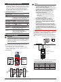
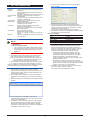
User’s
Manual
Model VJET
Ethernet/RS-485 Converter
Network Solutions Business Division
2-9-32, Naka-cho Musashino-shi, Tokyo 180-8750 Japan
Phone: +81-422-52-7179 Facsimile: +81-422-52-6973
Thank you for purchasing the JUXTA Signal Conditioner.
Please read through this manual before use for correct handling.
IM 77J01E11-01E
4th Edition Feb. 2012 (YK)
1. MOUNTING METHOD
CAUTIONARY NOTES FOR SAFE USE OF THE
PRODUCT
NOTE
This User’s Manual should be carefully read before installing and
operating the product. Please keep this User's Manual for future
reference.
The following symbol is used on the product and in this manual to
ensure safe usage.
●● Insert/pull out the main unit into/from the socket
vertically to the face of socket. Otherwise the
terminals are bent and it may cause a bad contact.
●● When using the VJET for side-by-side multiple
mounting, mount the VJET in either the left or right
end of the mounted instruments.
This symbol is displayed on the product when it is
necessary to refer to the User's Manual for information
on personal and instrument safety. This symbol is
displayed in the User's Manual to indicate precautions
to avoid danger to the operator, such as an electric
shock.
1.1 Wall Mounting
Loosen the main unit-fixing screw of the product and pull out the
main unit from the socket. Fix the socket on the wall with screws.
Next, insert the main unit into the socket and fasten the main unit
with the main unit-fixing screw.
Mounting Dimensions
Mounting screws
The following symbols are used only in this manual.
29.5 or more
NOTE
Socket
Main unit
Draws attention to essential information for
understanding the operations and/or functions of the
product.
22±0.2
Unit: mm
2-M4 or
2-ø4.5 or more
59±0.3
Threaded hole for
fixing the main unit
CHECKING PRODUCT SPECIFICATIONS
AND PACKAGE
(1) Checking the Model and Product Specifications
Check that the model and specifications indicated on the
nameplate attached to the main unit are as ordered.
(2) Packaged Items
Check that the package contains the following items:
•• VJET: 1
•• Tag number label : 1
•• Terminator: 1 (When option code “/R220” is specified.)
•• User’s Manual (this manual): 1
Main unit-fixing screw
1.2 DIN Rail Mounting
Insert a DIN rail into the upper part of the DIN rail groove on the
rear of the socket, and then slide the slide lock at the lower part of
the socket upwards until the socket is fixed into position as shown
below.
Fit into here
DIN rail
GENERAL
The VJET is a compact, plug-in type communication converter. It
can be connected to the host devices with Ethernet by Modbus/
TCP protocol, and to the instruments with RS-485 by Modbus/
RTU protocol.
DIN rail
Push
(Rear of socket)
MODEL AND SUFFIX CODES
Model Suffix codes
VJET
-0 1
-0 1
□ -1 0
0
0 /□
Description
[Style: S2]
Ethernet/RS-485 Converter
Always -01
3
24 V DC ±10%
Power supply
6
100-240 V AC/DC*
-1 0 0 0
Always -1000
Blank: With socket
Option
/SN
Without socket
/R220 Attachment of a terminator (220 Ω)
*: Operating range: 85 to 264V AC/DC
DIN rail
Slide lock
1.3 Mounting Using a Multi-mounting Base
When using a multi-mounting base, see the User’s Manual for
VJCE-01A (VJ Mounting Base for communication) (IM 77J01C5111E).
1.4 Using a Duct
When using a wiring duct, install the duct at leaset 30 mm away
from the top and bottom faces of the main unit.
1
2. INSTALLATION LOCATION
NOTE
•• Avoid the following environments for installation locations:
Areas with vibration, corrosive gases, dust, water, oil, solvents,
direct sunlight, radiation, a strong electric field, and/or a strong
magnetic field, altitude of more than 2000m above sea level.
•• If there is any risk of a surge being induced into the power
line and/or signal lines due to lightning or other factors, a
dedicated lightning arrester should be used as protection for
both this converter and a field-installed device.
Environmental Conditions
Operating
0 to 50°C
temperature range
Operating humidity 5 to 90% RH (no condensation)
range:
Ambient Condition Avoid installation in such environments as
corrosive gas like sulfide hydrogen, dust,
sea breeze and direct sunlight. Installation
altitude 2000m or less above sea level.
●● Do not connect anything to the terminals that are
not used in the wiring diagram. Otherwise it may
cause the malfunction or damage.
●● The power line and input/output signal lines should
be installed away from noise-generating sources.
Otherwise accuracy cannot be guaranteed.
●● Adhere strictly to the specifications to avoid
overheating or damage. Before turning on the
power, ensure the following:
••Power supply voltage and input signal value
applied to the product should meet the required
specifications.
••The external wiring to the terminals and wiring to
ground are as specifications.
●● Do not operate the product in the presence of
flammable or explosive gases or vapors.
●● This product is sensitive to static electricity;
exercise care in handling. Before you operate the
product, touch a nearby metal part to discharge
static electricity.
●● The grounding resistance must be 100 Ω or less
(JIS Class D grounding). The length and thickness
of the grounding cable should be as short and thick
as possible. Directly connect the lead from the
ground terminal (terminal no. 8) of the product to the
ground. Do not carry out daisychained inter-ground
terminal wiring
Power Supply and Isolation
Power Supply
24 V DC or 100-240 V AC/DC 50/60 Hz
Rated Voltage:
Power Supply
24 V DC (±10%) or 100-240 V AC/DC
Input Voltage:
(−15%, +10%) 50/60 Hz
Power
1.8 W at 24 V DC; 1.5 W at 110 V DC
consumption:
2.6 VA at 100 V AC, 4.0 VA at 200 V AC
Insulation
100 MΩ minimum at 500 V DC between
resistance:
Ethernet, RS-485, power supply and
grounding terminals mutually
Withstanding
1000 V AC for one minute between Ethernet
voltage:
and RS-485 terminals mutually
2000 V AC for one minute between
(Ethernet, RS-485), power supply, and
grounding terminals mutually
•• Connet the VJET to the host device using either 10BASE-T
or 100BASE-TX. The VJET detects 10BASE-T or 100BASETX automatically. 10BASE-T/100BASE-TX are 10 Mbps/100
Mbps Ethernet standard using twisted-pair cables. In
10BASE-T/100BASE-TX networks, personal computers and
other host devices are connected in a star pattern through a
hub.
3. EXTERNAL WIRING
WARNING
Devices that can be connected to Ethernet
PC
Touch panel
Be sure to turn OFF the power supply before wiring to
avoid the risk of electric shock. Use a tester or similar
device to ensure that no power is being supplied to a
cable to be connected.
or
HUB
Ethernet
Wiring should be connected to the terminals on the socket of the
product. The terminals for external connections are of M3 screws. Use
crimp-on terminal lugs for connections to the terminals.
•• Recommended cables: A nominal cross-sectional area of
0.5 mm2 or thicker for signal cables, and that of 1.25 mm2 or
thicker for power cables.
Wiring Diagram
Terminator
Activity LED
Connector for
10BASE-T/100BASE-TX
Terminator
Link LED
2
Power supply
L+
N−
GND
6
5
RS-485
communication
10
2
B+
11
5
A−
6
COM
8
8
The VJET has Link LED (lower side) and Activity LED (upper
side) on the connector part of the front. These LEDs turn on
in green or amber. (see the External Dimensions.)
Link LED (Lower side)
11 10
VJET
Terminating
resister
220 Ω
VJ series
VJ series
Signal Conditioner Signal Conditioner
B+
2
B+
2
B+
2
A−
5
A−
5
A−
5
COM
(SG)
COM
(SG)
COM
(SG)
6
6
6
Activity LED (Upper side)
Color
Meaning
Color
Meaning
Off
No Link
Off
No Activity
Amber
10 Mbps
Amber
Half-Duplex
Green
100 Mbps
Green
Full-Duplex
Terminating
resister
220 Ω
Class D grounding (grounding resistance of 100 Ω or less)
2
IM 77J01E11-01E
4th Edition
Feb, 08. 2012-00
6. From the Tool, click Upload from VJET. The dialog box
below appears.
4. SETTING PARAMETERS
4.1 Operating Enviroment
Operating
system:
Recommended
CPUs:
Recommended
Main Memory:
Hard disk:
CRT display:
Network:
Windows XP (Home Edition/Professional) (32bit version)
Windows Vista Business (with Service Pack 1)
(32-bit version)
Windows 7 Professional (32-bit/64-bit versions)
300 MHz pentium processor or superior is
recommended.
(3.0 GHz or higher in Windows Vista Business/
Windows 7 Professional)
128 MB minimum for Windows XP (Home
Edition/Professional)
Windows Vista Business/Windows 7
Professional; 2 GB or more
Memory space required to store the tool’s
programs; 10 MB minimum
Memory space required to store the parameter
data; 2 MB minimum
800 × 600 pixels or superior
Smaller fonts should be used.
Should be capable of handing at least 256
colors.
10BASE-T/100BASE-TX (required for Ethernet
communication)
7. Change the settings for High-speed response mode,
Parity, IP address, Subnet mask, Default gateway and port
number *2, and then click OK. The settings are changed
and the first dialog box appears.
(It takes about 10 seconds to change the settings.)
8. The change of settings is completed if the changed settings
are displayed in the first dialog box.
Factory-set defaults
High-speed response mode: 0 (OFF) *1
Parity:
1 (Even)
IP address:
192.168.1.1
Subnet mask:
255.255.255.0
Default gateway:
0.0.0.0
Port number:
502
4.2 Installation
NOTE
●● Before installing the tool, quit all running
applications.
●● When using Windows XP
••Log on using the user name of Administrators group.
••The program dose not start normally if the user name
not belonging to the Administrators group is used for
logging on.
*1 The High-speed Response Mode improves the response
performance of reference numbers 40001 to 40025 of
RS-485 connection devices. The Mode can be set to a
maximum of eight devices. Setting the number of devices
using the VJET setting tool applies the Mode to the
connection devices for Unit ID 1 to the set number.
* The period to read the process data from RS-485
connection devices cannot be specified. The VJET
automatically reads the process data at the highest
speed corresponding to the number of RS-485
connection devices for which this function (High-speed
Response Mode) is used.
* If the function is used for many RS-485 connection
devices, the process data from each RS-485 connection
device stored in the VJET may be delayed to the actual
process. In this case, turn off the function.
*2 The setting rang for the port number (PRT) is as follows.
502, 1024 to 65535 (decimal number)
01F6, 0400 to FFFF (hexadecimal number)
1. Start Windows.
2. Download the VJET setting tool from the following URL.
http://www.yokogawa.com/ns/cis/field/ns-vjet_01.htm
Note:The setting tool of old version may not be able to set
the VJET settings. Download the newest version of
the setting tool from the URL above to use it.
3. Please extract a compressed file and perform SETUP.EXE.
4. To continue, follow the instructions appearing on screen.
After the installation is completed, the VJET setting tool is added
to the Programs submenu of the Start menu of Windows.
4.3 VJET Setting Tool Basics
1. Set the network settings of the personal computer.
(For initial setup, connecting a VJET and a PC using cross
cable is recommended. Ask the system administrator for
the settings and contents.)
2. From the Start menu of Windows, point to the Programs
submenu then VJET Setting Tool, and click VJET Setting
Tool.
3. The VJET Setting Tool then starts and the dialog box below
appears.
4. The connected VJET is displayed. (If the VJET is
connected after starting the tool, click Tool on the Menu bar
and then choose Research.)
5. Choose the VJET of which the setting are to be changed
from the displayed VJET. If multiple VJET are displayed,
identify them by Mac address. (Mac address: The seal
showing the 12-digit alphanumeric character is attached to
the sideface of the VJET main unit.)
3
IM 77J01E11-01E
4th Edition
Feb, 08. 2012-00
5. COMMUNICATION OVERVIEW
5.3 Network Frame Structure
The Modbus/TCP frame structure is as follows:
5.1 Communication Specifications
Modbus TCP/IP ADU
Ethernet Specifications
Interface
Conforms to IEEE802.3 (10BASE-T/100BASETX)
Port number for Modbus/TCP protocol: 502
MBAP Header
Access control
Transfer rate
Maximum
segment length
Maximum
connecting
configuration
MBAP Header (Modbus Application Protocol Header)
Header used to identify the the Modbus/TCP protocol
PDU (Simple Protocol Data Unit)
Body of the data communication
MODBUS/TCP
TCP
IP
Ethernet
10BASE-T/100BASE-TX
5.3.1 MBAP Header Structure
The MBAP Header (Modbus Application Header) consists of
the following seven bytes.
Byte No.
CSMA/CD
10 Mbps/100 Mbps
100 m (the length between Hub and converter)
Description
Protocol ID:
Communication High-speed response mode, parity, IP address,
parameter
subnet mask, default gateway and port number
settings
via Ethernet using the dedicated tool.
Number of
bytes:
Unit ID:
RS-485 Specifications
Interface
Conform to EIA RS-485
Protocol
Modbus/RTU
Transfer system Half-duplex communication
S y n c h r o n o u s Start-stop synchronization
system
Transfer rate
9600 bps
Parity
Even, odd or none
Stop bit
1 bit
Data length
8 bit
socket()
3
4
5
Number of
bytes
6
Unit
ID
The host device specifies an arbitrary
value to identify a trasaction.
The VJET returns the value it received
from the host device as its response.
This parameter is set to “0” to indicate
the Modbus/TCP protocol.
The number of bytes from the Unit ID
(byte number 6) byte on.
Unit ID of RS-485 connection device.
Byte No.
0
1 to (n−1)
Description
Function code
Data
Function code:
Data:
RS-485 connection
devices
socket()
2
Protocol
ID
The PDU (Simple Protocol Data Unit) consists of the
following n bytes.
Modbus/TCP exchanges data with the protocol shown in the
figure below using a TCP/IP socket interface.
First startup
1
5.3.2 PDU Structure
5.2 TCP/IP Communication
First startup
0
Transaction
ID
Transaction ID:
Up to 4 cascade connections per hub
(10BASE-T), up to 2 cascade connections per
hub (100BASE-TX)
PC
Data
PDU
Host devices (PC, etc.)
Application layer
Transport layer
Network layer
Data link layer
Physical layer
Function codes
The command specified from the host
device.
Depending on the function code, D
register addresses, the number of
individual D registers, or parameter
values are specified in this position.
5.4 List of Function Codes
The codes in the following list are command words host devices
use to acquire information from the internal registers (D registers)
of RS-485 connection devices.
Code Number
03
06
08
16
Signal Conditioners
JUXTA series
Controllers
GREEN series
UT100 series
Power Monitors
POWERCERT series
bind()
Function
Reads data from multiple registers
Writes data to registers
Loop back test
Writes data to multiple registers
For details, refer to the Communication Functions user’s
manual of each RS-485 connection device.
listen()
Open connection
accept()
connect()
Command
send()
recv()
Response
NOTE
recv()
send()
Terminate connection
close()
close()
If no request is received from the host device for more
than 60 seconds after establishing a connection, the
VJET will automatically terminate the connection.
4
IM 77J01E11-01E
4th Edition
Feb, 08. 2012-00
6. EXAMPLE OF COMMUNICATION
PROGRAM
’ Explanation of command character string
’ 1234 0000 0006 01 03 0001 0004
’ |
|
|
| | |
+---Number of D register (4)
’ |
|
|
| | +---D register start number (D0002)
’ |
|
|
| +---Funcion code (03: Read data from
’ |
|
|
|
multiple registers)
’ |
|
|
+---RS-485 connection device address (Address: 1)
’ |
|
+---The number of sending data bytes after
’ |
|
“RS-485 connection device address” (6 bytes)
’ |
+------Protocol ID (0000 fixed)
’ +------Transaaction ID (1234: Arbitrary value of 2 bytes)
’
varChrs = StrConv(strSendData, vbFromUnicode) ’To change
sending command character string into binary data
This chapter shows a sample program to read/write data
operating by Microsoft Visual Basic 6.0. The program shown
here is for your reference when you create a program. All
operation is not guaranteed.
’/////////////////////////////////////////////////////////////////////////////////////////////////////////////////////
’
’Example of VJET Communication Procedure by Microsoft Visual Basic
6.0
’
’
’Procedure to read the input value of VJU7 (Address: 01) via VJET from
LAN port of a PC.
’Connect and send command by Connect, SendData of Winsock control,
and receice data by DataArrival event.
’Procedure to connect to VJET by TCP/IP, create command and send the
command.
’
’ [ PC ]
’
|
’
|
’ --+-----+-------- Ethernet
’
|
’
[VJET] IP Adr:192.168.1.101
’
|
’
+--[VJU7]Address:01
’
RS485BUS|
’
+--[VJU7]Address:02
’
| :
’
’
’The following procedure is described using the real numbers and real
character strings for explanation. Check error processing and retry
processing in normal conditions are omitted. The program does not
operate only by this procedure. Please make it the refernce at the time of
actual application creation.
’
’/////////////////////////////////////////////////////////////////////////////////////////////////////////////////////
’
’-------------------------------------------------------------------------------------------------’Variable declaration
’
Option Explicit
’Sending data
Dim strSendData As String
Dim strReceive As String
’Received data
Dim binChrs(11) As Byte
’Store binary data
Dim i As Integer
’Variable declaration
’
’-------------------------------------------------------------------------------------------------Private Sub cmdSend()
’
’Procedure to connect to VJET by TCP/IP, create command and send the
command.
’
’
’Variable declaration
’
Dim sChr2 As String
Dim varChrs As String
’
’Set properties of Winsock control
’
Winsock1.Protocol = sckTCPProtocol
’Set protocol used for TCP
connection
Winsock1.RemoteHost = “192.168.1.101” ’Set IP address of VJET
Winsock1.RemotePort = 502
’Set a port of VJET (502: default)
’
’Request TCP connection of VJET
’
Winsock1.Connect
’Request TCP connection
Do Until Winsock1.State = sckConnected
’Wait for the
comletion of connection
i = DoEvents()
Loop
’
’Create sending data
’
’
’Create command to read input value data and D register addresses from
“D0002” to “D0005” of VJU7 (Address: 01) connected to RS-485 of VJET.
D0002: Input value (engineering unit); D0003: Number of digits below
decimal popint; D0004: Input value (ratio of input to span, %); D0005: Unit
of input value (engineering unit)
’
’
strSendData = “123400000006010300010004” ’Sending command
character string
’
For i = 1 To 12 ’Change every two character strings into Unicode and arrange
them to store in binDhrs
sChr2 = MidB(varChrs, 2 * i - 1, 2)
binChrs(i - 1) = CByte(“&H” & StrConv(sChr2, vbUnicode))
Next i
’
’Send sending command binChrs to VJET
’
Winsock1.SendData binChrs
’
End Sub
’-------------------------------------------------------------------------------------------------Private Sub Winsock1_DataArrival(ByVal bytesTotal As Long)
’
’Receive data from VJET DataArrival of Winsock and cut connection with
VJET.
’
’
’Variable declaration
’
Dim strData() As Byte
Dim strHex1 As String
Dim strReceive As String
Dim varReceive As String
’
’Receive data from VJET
’
Winsock1.GetData strData
’Get received data of Winsock1 control
into strData
’
’Change received binary data strings to character strings.
’
’
For i = 0 To bytesTotal - 1
varReceive = varReceive & ChrB(strData(i))
Next i
’
For i = 1 To LenB(varReceive)
strHex1 = Right(“0” & Hex(AscB(MidB(varReceive, i, 1))), 2)
strReceive = strReceive & strHex1
Next i
’Received data character string are stored in strReceive
’
’Example of received characters strReceive from VJU7 (Instrument range: 0
to 1000 °C; Input value: 680.2 °C)
’
’ 1234 0000 000B 01 03 08 1A92 0001 02A8 0003
’ | | | | | | | | | |
’ | | | | | | | | | +--D0005 register
| | | | | | | | | data (Unit: 3=°C)
’ | | | | | | | | +--D004 register data (Input value %: 02A8h=680:68.0)
’ | | | | | | | +--D0003 register data (Number of digits below decimal pont: 1)
’ | | | | | | +--D0002 register data (Input value: 1A92h=6802: 680.2)
’ | | | | | +--Data amount bytes (8 bytes)
’ | | | | +--Function code (03: Read data from mutiple registers) |
’ | | | +--RS-485 connection device address (Address 1) | |
’ | | +--The number of send data bytes after “RS-485 connection device address” (000Bh=11 bytes)
’ | +--Protocol ID (0000 fixed)
’ +--Transaction ID (The value when sending 1234 command)
’
’Cut TCP connection
’
Winsock1.Close
’
End Sub
’-------------------------------------------------------------------------------------------------’
’/////////////////////////////////////////////////////////////////////////////////////////////////////////////////////
5
IM 77J01E11-01E
4th Edition
Feb, 08. 2012-00
7. TROUBLESHOOTING
If the devices can not communicate each other, perform the
following checks.
□ All devices related to the communication are turned on.
□ The wiring is correct.
□ The VJ series with Output-2 other than communication is not
connected.
□ The number of connected devices and connecting distance
are within the use range.
□ The communication conditions of RS-485 connection device
are as follows.
□ Protocol: Modbus/RTU
□ Baud rate: 9600 bps
□ Data length: 8 bits
□ Stop bit: 1 bit
□ The Unit ID specified for sending by a host device and the Unit
ID of the connected RS-485 connection device are consistent.
□ The parity is consistent between VJET and RS-485 connection
device.
□ The same Unit ID is not set for the devices connected to the
same communication line.
□ The port number is correct.
TRADEMARKS
•• Windows XP, Windows Vista, and Windows 7 are trademarks
of Microsoft Corporation, U.S.A.
•• Pentium is a registered trademark of Intel Corporation, USA.
•• Ethernet is registered trademark of XEROX corporation.
•• Other proper nouns such as trade names and company
names are trademarks of their respective companies.
6
IM 77J01E11-01E
4th Edition
Feb, 08. 2012-00