1
Acknowledgements
TRADEMARKS
User's Manual
Apple, LaserWriter, and TrueType are registered trademarks of Apple Computer.
Centronics is a registered trademark of Centronics Corporation.
Chipstrip is a trademark of South-Pak, Inc.
Epson is a registered trademark of Epson Corporation, Epson America,Inc.
IBM is a Trademark of International Business Machines Corporation.
IGP is a Trademark of PRINTRONIX Corporation.
LaserJet and HP PCL5 are registered trademarks of Hewlett Packard Corporation.
LaserMatrix is a registered trademark of Output Technology Corporation.
Lotus is a registered trademark of Lotus Development Corporation.
PrintCenter 24
Microsoft and TrueImage are registered trademarks and Windows is a trademark
of Microsoft Corporation.
Novell is a registered trademark of IBM Corporation.
PCL is a Trademark of Hewlett-Packard Corporation.
PostScript is a registered trademark of Adobe Systems, Inc.
ProPrinter is a registered trademark of IBM Corporation.
Teflon is a registered trademark of DuPont de Nemours.
Tyvek is a registered trademark of DuPont Co.
WordPerfect is a registered trademark of WordPerfect Corporation.
Typefaces mentioned in this publication are products, tradenames, and trademarks
(registered or otherwise) of third parties and do not belong to Output Technology.
PROPRIETY
This product contains propriety information and trade secrets designed and
developed by Output Technology Corporation, The Peerless Group, and Agfa
Corporation.
Output Technology Corporation - 3808 N. Sullivan Road Bldg. #3
Spokane, WA 99216 - USA
(509) 536-0468
We suggest you use genuine Output Technology Corporation supplies and
authorized service centers. Please contact us at —
Voice: 1-800-468-8788 — Fax: (509) 533-1280
For service, please have your printer model and serial numbers handy — these are
located on the side of the printer.
WWW:
http://www.output.com
Safety Regulations for the PrintCenter 24
Electromagnetic Compatibility
We certify that the equipment at issue,
The PrintCenter 24 fulfils the safety regulations according to IEC and
TÜV/GS for computer systems (EN 60950) and laser products (EN
60825-1).
UL 1950 3rd Edition / CAN/CSA C22.2 No 950-95; 21 CFR 1040.10 and
1040.11.
Type: PrintCenter 24
corresponds to the law regulations ruling electromagnetic compatibility of
appliances (89/336/EWG) and, therefore, fulfils the requirements for
conformity marking with the CE-sign.
The mains cable must be connected to a ground protected wall-socket.
The selected voltage of the printer needs to be in accordance with the
local mains voltage.
Note:
The power plug must be easily accessible at any time so that it can be
disconnected immediately in case of danger or for maintenance
purposes.
Before installing the printer, check the surrounding conditions in which the
printer is intended to be used (see next page, Operating Environment).
During thunderstorm you should never attempt to connect or disconnect
any data transfer cable.
The power supply should only be opened and checked by authorized
personnel. Repairs and maintenance beyond the descriptions of chapter
4 may only be attempted by authorized personnel as well. Repairs done
inappropriately may cause damage to the device and severe danger for
the user.
Caution:
This equipment has been tested and found to comply with the
limits for a CLASS A digital device pursuant to Part 15 of the
FCC Rules. These limits are designed to provide reasonable
protection against harmful interference when the equipment is
operated in a commercial environment. This equipment
generates, uses, and can radiate radio frequency energy and, if
not installed and used in accordance with the instruction manual,
may cause harmful interference to radio communications.
Operation of this equipment in a residential area is likely to
cause harmful interference in which case the user will be
required to correct the interference at his own expense.
To guarantee that the device stays within the limits according to the
approval regulations for conducted and radiated emission (EN 55022,
Class B) and immunity according to EN 50081-1, Generic Standard. In
any case, shielded interface cables are only to be used.
Changes and modifications not explicitly allowed by the equipment's
manufacturer could void the user's authority to operate the equipment.
The use of controls or adjustments or performance of
procedures other than those specified herein may result in
hazardous radiation exposure.
During the printing process ozone will be
produced. Take care that the printer is
standing in a room with good ventilation. The
limit of ozone concentration should be 0,1
ppm (0,2 mg/m3). Note that the specific gravity
of ozone is higher than air.
I
Operating Environment
Avoid installing the printer where it is exposed to moisture or heat (eg.
direct sun light).
Temperature: + 10°C to + 32.5°C (+50°F to +90.5°F)
Humidity: 20% to 80%
Slots and openings in the printer's housing are provided for ventilation. Always
ensure that these openings are not obstructed.
Also ensure that the cables at the rear of the printer do not interfere with the output
paper path.
II
CAUTION
ACHTUNG
Although the toner used in this printer is non-toxic, its super-fine
texture and susceptibility to heat can cause problems if spilled.
Obwohl der in diesem Drucker benutzte Toner nicht giftig ist, kann
er, falls verschüttet, Probleme verursachen, weil er superfein und
hitzeempfindlich ist.
NEVER reship or move the printer with the drum cartridge, developer
unit, or waste toner bottle in the printer. ALWAYS remove these
customer replaceable items.
ALSO, NEVER ship an open, used, or partially used drum cartridge,
developer unit, or waste toner bottle.
The manufacturer is not liable for damage to the printer or other items
when the printer is shipped or moved with the drum cartridge, developer
unit, and/or waste toner bottle in place. Also, various governmental
regulations may prohibit shipping of these items.
AVERTISSEMENT
Bien que l'encre utilisée dans cette imprimante ne soit pas toxique,
elle est sensible à la chaleur et d'une texture extrèment fine et peut créer
des problèmes si renversée.
N'expédiez ni ne déplacez JAMAIS l'imprimante avec la cartouche
d'encre, l'unité de développement et la bouteille d'écoulement d'encre
usagée installées. Retirez TOUJOURS ces articles au préalable.
Der Drucker darf NIEMALS wieder versandt oder bewegt werden,
solange sich Tonerkartusche, Entwicklereinheit und Resttonerbehälter
noch darin befinden. Diese vom Kunden auswechselbaren Artikel
müssen IMMER erst entfernt werden.
Offene, gebrauchte oder teilweise aufgebrauchte Tonerkartuschen
oder Resttonerbehälter dürfen AUCH NIEMALS versandt werden. Falls
eine gebrauchte Entwicklereinheit versandt werden muß, darf sie nur
zusammen mit der daran befestigten Tonerkartusche verschickt werden;
Entwicklereinheit und Tonerkartusche müssen in einen sicheren,
vollkommen luftdichten und lecksicheren, haltbaren Versandbehälter mit
der Aufschrift "VORSICHT!" verpackt werden.
Der Hersteller haftet nicht für Schäden an Druckern oder anderen
Gegenständen, wenn Drucker zusammen mit den darin befindlichen
Tonerkartuschen, Entwicklereinheiten und/oder Resttonerbehältern
versandt oder bewegt werden. Außerdem könnten gewisse staatliche
Vorschriften den Versandt von Tonerkartuschen und Resttonerbehältern
untersagen.
DE SURCROIT, n'expédiez JAMAIS une cartouche d'encre ou une
bouteille d'écoulement d'encre usagée ouvertes, entamées ou usagées.
Expédiez toujours les unités de développement usagées avec la
cartouche d'encre installée ; l'unité de développement contenant la
cartouche d'encre doit être emballée dans un conteneur solide, résistant
et parfaitement hermétique et étanche marqué "MANIEMENT SPECIAL".
Le fabricant n'est pas responsable des dégâts causés à l'imprimante
ou à d'autres articles par suite de l'expédition ou du déplacement de
l'imprimante avec la cartouche d'encre, l'unité de développement et/ou la
bouteille d'écoulement d'encre installées. Il se peut de surcroit que
certains règlements gouvernementaux interdisent l'expédition des
cartouches d'encre et des bouteilles d'écoulement d'encre.
III
IV
Il fabbricante non è responsabile di eventuali danni alla stampante
o ad altri articoli quando la stampante è spedita senza previa rimozione
della cartuccia del toner, dello sviluppatore e/o della bottiglia del toner
usato. E' possibile inoltre che certe norme governative vietino la
spedizione di cartucce di toner e bottiglie del toner usato.
PRECAUCION
A pesar de que el pigmento de esta impresora no es tóxico, su
textura extremadamente fina y su susceptibilidad al calor pueden
presentar dificultades en caso de derramarlo.
NUNCA transporte ni mueva la impresora con el cartucho de
pigmento, la unidad reveladora y el recipiente de desecho de pigmento
instalados. SIEMPRE retire estos elementos reemplazables por el
usuario.
IMPORTANT SAFETY INSTRUCTION
DANGER: LASER LIGHT CAN DAMAGE
EYES. DO NOT look directly at a laser lamp. DO
NOT open the top cover while the printer is
operating.
Además, NUNCA transporte un cartucho de pigmento abierto o
usado parcial o totalmente, ni tampoco un recipiente de desecho de
pigmento. Si se debe transportar una unidad reveladora, debe hacérselo
junto con el cartucho de pigmento; la unidad reveladora con el cartucho
de pigmento deben empacarse en una caja segura, absolutamente
hermética y a prueba de fugas, de gran resistencia, rotulada "MANEJESE
CON ESPECIAL CUIDADO".
DANGER: LES RAYONS LASER SONT
DANGEREUX POUR LES YEUX. NE PAS
regarder directement une lampe laser.
NE PAS ouvrir le couvercle d'une imprimante en
cours d'opération.
El fabricante no se hace responsable por los daños a la impresora o
a otros elementos transportados o trasladados con el cartucho de
pigmento, la unidad reveladora y/o el recipiente de desecho de pigmento
instalados. Además, los reglamentos gubernamentales pueden prohibir
el transporte de cartuchos de pigmento y de recipientes de desecho de
pigmento.
VORSICHT: LASERLICHT KANN ZU
AUGENSCHÄDEN FUHREN. NICHT direkt auf
eine Laserlampe schauen. Bei Betrieb des
Druckers NICHT den Gehäusedeckel öffnen.
PELIGRO: LAS RADIACIONES LASER
PUEDEN DAÑAR LA VISTA. NUNCA dirija su
vista a la lámpara lasérica. NO abra la tapa
superior mientras la impresora funcione.
ATTENZIONE
PERICOLO: LA LUCE LASER PUO' RECARE
GRAVI DANNI AGLI OCCHI. NON guardare
direttamente la lampada laser. NON aprire il
coperchio della stampante, quando essa è in
funzione.
Sebbene il toner nella stampante sia atossico, la sua sensibilità al
calore e la sua composizione estremamente fine possono causare
problemi se rovesciato.
NON rispedire o spostare la stampante prima di aver rimosso la
cartuccia del toner, lo sviluppatore e la bottiglia del toner usato.
Rimuovere SEMPRE questi articoli prima della spedizione.
MAI spedire una cartuccia di toner o una bottiglia di toner usato
aperta, o parzialmente usata. E' inoltre necessario spedire lo
sviluppatore con la cartuccia del toner installata. Lo sviluppatore con la
cartuccia del toner installata deve essere imballato in un contenitore
rigido ed a tenuta ermetica etichettato "MANEGGIARE CON CURA".
V
VI
Table of Contents
2. Printer Operation . . . . . . . . . . . . . . . . . . . . . . . . . . . . . . . . . . . . . .
2.1
Control Panel . . . . . . . . . . . . . . . . . . . . . . . . . . . . . . . . . . . .
2.1.1
Description of the Four Indicators . . . . . . . . . . . . . .
2.1.2
Description of the LCD Display . . . . . . . . . . . . . . . .
2.1.3
Function Keys . . . . . . . . . . . . . . . . . . . . . . . . . . . . .
Table of Co ntents
Preface . . . . . . . . . . . . . . . . . . . . . . . . . . . . . . . . . . . . . . . . . . . . . . . . . XI
About this Manual . . . . . . . . . . . . . . . . . . . . . . . . . . . . . . . . . . . . . . . . . XI
1. Getting Started . . . . . . . . . . . . . . . . . . . . . . . . . . . . . . . . . . . . . . . .
1.1
Unpacking . . . . . . . . . . . . . . . . . . . . . . . . . . . . . . . . . . . . . . .
Printer Package . . . . . . . . . . . . . . . . . . . .
Contents of Starter Kit Box . . . . . . . . . . . .
Transportation Hints . . . . . . . . . . . . . . . . .
1.2
1-1
1-1
1-1
1-2
1-4
Installing the Consumables . . . . . . . . . . . . . . . . . . . . . . . . . . 1-5
Installing the Developer Unit . . . . . . . . . . . 1-6
Filling in Starter Toner . . . . . . . . . . . . . . . 1-8
Inserting the Ozone Filter . . . . . . . . . . . . 1-10
Installing the Waste Toner Container . . . 1-11
Inserting the Cleaner Felt . . . . . . . . . . . . 1-12
Installing the OPC Drum . . . . . . . . . . . . . 1-13
1.3
The Power Supply . . . . . . . . . . . . . . . . . . . . . . . . . . . . . . . . 1-14
1.4
Power ON/OFF Switch . . . . . . . . . . . . . . . . . . . . . . . . . . . . 1-15
1.5
Inserting Fanfold Paper . . . . . . . . . . . . . . . . . . . . . . . . . . . . 1-17
Installation of Paper Guides . . . . . . . . . . 1-17
Inserting Paper/Changing Paper Width . 1-19
1.6
Connection to the Computer . . . . . . . . . . . . . . . . . . . . . . . . 1-21
1.7
Connecting the Stacker System . . . . . . . . . . . . . . . . . . . . . 1-22
VII
2-1
2-1
2-1
2-2
2-3
2.2
Menu Mode . . . . . . . . . . . . . . . . . . . . . . . . . . . . . . . . . . . . . . 2-4
2.2.1
Activate the Menu . . . . . . . . . . . . . . . . . . . . . . . . . . 2-5
2.2.2
Confirm a new Selection . . . . . . . . . . . . . . . . . . . . . 2-6
2.3
Status and Error Messages . . . . . . . . . . . . . . . . . . . . . . . . . . 2-7
3. Configuring the Printer . . . . . . . . . . . . . . . . . . . . . . . . . . . . . . . . . 3-1
3.1
What is Configuring? . . . . . . . . . . . . . . . . . . . . . . . . . . . . . . . 3-1
3.2
Printout of Standard Configuration . . . . . . . . . . . . . . . . . . . . 3-3
3.3
Configuration Programs . . . . . . . . . . . . . . . . . . . . . . . . . . . . 3-6
3.3.1
Installation . . . . . . . . . . . . . . . . . . . . . . . . . . . . . . . . 3-6
3.3.2
Profiler . . . . . . . . . . . . . . . . . . . . . . . . . . . . . . . . . . 3-7
3.4
Explanation of the Menu Items . . . . . . . . . . . . . . . . . . . . . . 3-12
Menu Tree . . . . . . . . . . . . . . . . . . . . . . . . . . . . . . . . . . . . . . . . . . Menu-1
4. Maintenance . . . . . . . . . . . . . . . . . . . . . . . . . . . . . . . . . . . . . . . . . .
4.1
Installing the Parts of the Toner Kit . . . . . . . . . . . . . . . . . . . .
Filling in Toner . . . . . . . . . . . . . . . . . . . . .
Replacing the Waste Toner Container . . .
Changing the Cleaner Felt . . . . . . . . . . . .
4-1
4-1
4-2
4-4
4-6
4.2
Replacement of the OPC Drum . . . . . . . . . . . . . . . . . . . . . . 4-7
4.3
Replacement of the Developer Unit . . . . . . . . . . . . . . . . . . . 4-9
Filling in Starter Toner . . . . . . . . . . . . . . 4-11
Inserting the Ozone Filter . . . . . . . . . . . . 4-13
4.4
Replacement of the Fuser Unit . . . . . . . . . . . . . . . . . . . . . . 4-14
4.5
Exchanging the Control Unit . . . . . . . . . . . . . . . . . . . . . . . . 4-15
VIII
Table of Contents
5. Trouble Shooting and Diagnostics . . . . . . . . . . . . . . . . . . . . . . . 5-1
How to Use this Section . . . . . . . . . . . . . . . . . . . . . 5-1
5.1
Power-related Problems . . . . . . . . . . . . . . . . . . . . . . . . . . . . 5-2
5.2
Error Messages . . . . . . . . . . . . . . . . . . . . . . . . . . . . . . . . . . . 5-2
Appendix A Programming Guide . . . . . . . . . . . . . . . . . . . . . . . . . . . A-1
-Conventions . . . . . . . . . . . . . . . . . . . . . . . . . . . . . . . . . . . . . A-2
6. PrintCenter 24 Floor Model Stacker
1
PCL5 Extensions for Paper Size Selection . . . . . . . . . . . . . . A-3
6.1.
Assembling the PrintCenter24 Stacker . . . . . . . . . . . . . . . . . 6-1
6.1.1
Unpacking & Installation. . . . . . . . . . . . . . . . . . . . . . . . . 6-1
6.1.2
Assembly . . . . . . . . . . . . . . . . . . . . . . . . . . . . . . . . . . . 6-3
2
PJL Extensions . . . . . . . . . . . . . . . . . . . . . . . . . . . . . . . . . . . A-4
2.1
Basic Rules for PJL Programming . . . . . . . . . . . . . A-4
2.2
Supported Parameters in SET and DEFAULT
Statements . . . . . . . . . . . . . . . . . . . . . . . . . . . . . . . A-5
3
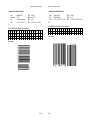
Barcode Programming . . . . . . . . . . . . . . . . . . . . . . . . . . . . . A-6
S
Programming . . . . . . . . . . . . . . . . . . . . . . . . . . . . . A-7
S
Barcode Print Position . . . . . . . . . . . . . . . . . . . . . . A-7
S
Barcode Print Orientation . . . . . . . . . . . . . . . . . . . . A-7
S
Barcode Type . . . . . . . . . . . . . . . . . . . . . . . . . . . . . A-8
S
Barcode Height . . . . . . . . . . . . . . . . . . . . . . . . . . . . A-9
S
Barcode Data . . . . . . . . . . . . . . . . . . . . . . . . . . . . . A-9
S
Barcode Text Control . . . . . . . . . . . . . . . . . . . . . . A-10
S
Barcode Module Width . . . . . . . . . . . . . . . . . . . . . A-10
S
Barcode Ratio . . . . . . . . . . . . . . . . . . . . . . . . . . . . A-11
S
Start and Stop Characters . . . . . . . . . . . . . . . . . . A-12
S
Barcode Programming Examples . . . . . . . . . . . . . A-13
6.2
Operating the PrintCenter24 Paper Stacker . . . . . . . . . . . . . 6-9
6.3
Troubleshooting . . . . . . . . . . . . . . . . . . . . . . . . . . . . . . . . . .
6.3.1
When it doesn’t run . . . . . . . . . . . . . . . . . . . . . . . . . .
6.3.2
When only one pair of coils turn . . . . . . . . . . . . . . . . .
6.3.3
When it doesn’t stack right . . . . . . . . . . . . . . . . . . . . .
6-13
6-13
6-13
6-13
6.4
Paper Motion Sensor . . . . . . . . . . . . . . . . . . . . . . . . . . . . . .
6.4.1
Installation . . . . . . . . . . . . . . . . . . . . . . . . . . . . . . . . .
6.4.2
Cleaning the Sensor . . . . . . . . . . . . . . . . . . . . . . . . . .
6.4.3
Sensitivity Adjustment . . . . . . . . . . . . . . . . . . . . . . . . .
6.4.5
Replacement Parts . . . . . . . . . . . . . . . . . . . . . . . . . . .
6-14
6-14
6-16
6-17
6-19
7. Technical Data . . . . . . . . . . . . . . . . . . . . . . . . . . . . . . . . . . . . . . . . 7-1
7.1
Printer Specification . . . . . . . . . . . . . . . . . . . . . . . . . . . . . . . 7-1
7.2
Paper Specification . . . . . . . . . . . . . . . . . . . . . . . . . . . . . . . . 7-3
7.3
Connectivity . . . . . . . . . . . . . . . . . . . . . . . . . . . . . . . . . . . . . . 7-4
7.4
Consumables . . . . . . . . . . . . . . . . . . . . . . . . . . . . . . . . . . . . 7-5
7.5
PC24 Floor Stacker Specification . . . . . . . . . . . . . . . . . . . . 7-6
7.6
Paper/Label Requirement for OTC Floor Model Stacker . . . . 7-7
IX
X
Preface
Preface
Description of assembling and operating the printer PC24 in
combination with Output Technology Corporation’s optional
PC24 Stacker and Paper Motion Sensor.
Preface
7.
About this Manual
This manual covers the printer including the Control Unit. The Control
Unit is an integral part of the printer which determines the functionality of
the printer especially regarding the user and system interface. Due to the
variety of Control Units different printer models are defined which, with
respect to the user interface however, all behave the same.
The structure of this manual is such that the operator is led step-by-step
through the various procedures. Starting with unpacking and installation
of the consumables it moves on to setting-up configuration parameters
and ends with the mounting of options.
Getting Started
This chapter covers the unpacking and setting-up of the printer
and the installation of the consumables. By the end of this
chapter the printer should be fully functional and tested in its
primary form. It is not yet connected to the host computer
system and no options are mounted.
2.
Operating the Printer
This chapter discusses in great detail the operation of the
operator panel, all menu functions, and the general operation of
the menu. General status messages are also described.
3.
Configuring the Printer
This chapter explains how to configure the printer so that it can
communicate with the corresponding system environment. Then
this chapter thoroughly describes the printer's operating
controls. In the last part you will find explanations of individual
menu items. At The end of this chapter you will find the Menu
Tree.
4.
Maintenance
This chapter explains how to replace the consumables.
5.
Trouble Shooting and Diagnostics
Suggests how to identify and correct simple problems.
6.
PrintCenter24 Floor Model Paper Stacker and Paper Motion
Sensor
XI
Technical Data
Provides Technical information about the printer PC24 and the
optional stacker system.
Appendix A
Programming information for page format control and printing of
resident BARCODE features are explained in this appendix.
Conventions Used in this Guide
The following conventions are used:
Bold
Headlines and important information.
Note:
Contains special advice to facilitate
handling.
Caution:
Contains important information to prevent
damage of the equipment.
[ENTER]
Key functions are always depicted in
brackets or indicated by the corresponding
symbol.
The manual is divided into the following chapters:
1.
Preface
XII
Getting started
1 Getting Started
1.1 Unpacking
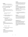
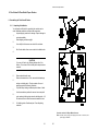
The PrintCenter 24 is delivered in two boxes, the larger one contains the
printer itself, the smaller one contains the Starter Kit. Check each box for
the contents on the list below. Contact your delivery agent immediately if
any item is missing or damaged.
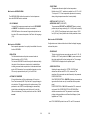
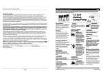
Contents of Starter Kit Box
- One Developer Kit consisting of:
- One Developer Unit (6)
- One Ozone Filter (7)
- One bottle with Starter Toner (8)
- One spout (9)
- One Cleaning Kit (10)
Printer Package
- Laser Printer (1)
- Control Unit (already mounted)
- User's Manual,Profiler and Drivers on CD (2)
Another small box contains:
- One (plastic) front paper guide (3)
- One (plastic) exit paper guide (4)
- One power cord (5)
- One OPC Drum (11)
Note:
The printer drivers & updates are available on Internet Address:
http://www.output.com
1-1
1-2
Getting started
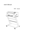
- One Toner Kit consisting of:
- Two Toner bottles (12)
- One spout (13)
- Two Waste Toner Containers (14)
- Two Cleaner Felts (15)
Getting started
Transportation Hints
Save all packing material and boxes for future transportation of the
printer.
To ensure maximum protection when transporting the printer, please pay
attention to the following:
1.
2.
3.
4.
5.
6.
Always remove the plastic paper guides and the power cord
Remove the Developer Unit
Empty the Toner box
Remove the OPC Drum
Remove the Waste Toner Container and lock it with the green cap
Put the printer into its original packing material and ship it its original
box
7. Put the Developer Unit into its original packing box.
8. Wrap the OPC Drum with stuffed antistatic foil and pack it light proof
into its original packing box.
Note:
Do not connect the printer to the mains until the mains voltage
selection has been checked and the consumables have been
installed (see the following pages).
1-3
1-4
Getting started
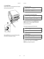
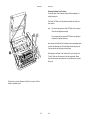
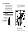
1.2 Installing the Consumables
Open the cover (20) by firmly pressing the button (21) at the left top
cover of the printer and swinging the cover up.
Remove the polyfoam transport lock (22) inside the printer, and located
underneath the Fuser Unit.
1-5
Getting started
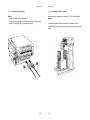
Installing the Developer Unit
Gently lift the plastic tabs (24) inside the printer, at the left and at the
right side of the cover, and pull the front cover (23) in a forward direction.
The front cover will only open to a 45 degree angle. Please do not force
this cover beyond a 45 degree angle.
1-6
Getting started
Now the rail guides inside the cabinet are free to accept the Developer
Unit.
Remove the Developer Unit (6) from its foil package and turn it so that
the sleeve roller (26) is toward the back of the printer.
Slide the Developer Unit fully into the printer along the plastic rails on the
left and right. To lock push down the two green plastic tabs.
Getting started
Filling in Starter Toner
Before using the Developer Unit for the first time, you have to fill it with
Starter Toner. One bottle of Starter Toner (8) with a spout (9) is in the
box of the Developer Unit. Shake the bottle several times to mix the
carrier and the toner. Carefully open the seal underneath the cap of the
toner bottle and attach the spout to the bottle. Open the top cover (28) of
the Developer Unit. Spread the toner evenly across the opening.
Note:
Do not squeeze the toner bottle since the toner could be blown out
of the hopper and contaminate the printer. If the toner bottle does
not completely empty, gently tap the end of the bottle while holding
it upside down over the hopper.
This first filling only allows Starter Toner to be used. Refilling any other
toner is not allowed before the message "Toner Low" appears on the
display.
1-7
1-8
Getting started
Getting started
Inserting the Ozone Filter
The box of the Developer Unit also contains an Ozone Filter (7), a black
rectangular block. On one of the narrow sides there is a small tab to hold
the filter. Insert the Ozone Filter into the slot immediately behind the
operator panel and beside the Developer Unit.
Close the top cover (28) of the Developer Unit. If you hear a "click" the
shutter is completely closed.
Firmly close the front cover (23).
1-9
1-10
Getting started
Installing the Waste Toner Container
The toner box contains two Waste Toner Containers (14). Take one of
them and insert it into its opening at the inner left side of the printer
immediately behind the Developer Unit. Be sure the green cap is on the
cap holder and not blocking the filling hole of the container.
1-11
Getting started
Inserting the Cleaner Felt
The toner box also contains two Cleaner Felts (15). Take one of them
and put it under the top cover of the Fuser Unit in the back of the printer.
After inserting the felt, the top cover does not lock completely. Don't
worry about this, the printer top cover will provide the necessary pressure
to keep the cleaner felt cover tight.
1-12
Getting started
Installing the OPC Drum
The OPC Drum (11) is packed separately in the Starter Kit. The OPC
Drum is very light-sensitive, so it is wrapped up in light proof foil.
Carefully remove the drum from its foil container.
Note:
Getting started
1.3 The Power Supply
Since an incorrect voltage selection can seriously damage the printer,
please pay special attention to the following:
Do not touch the green part of the OPC Drum with your fingers.
Oil and dirt degrade print quality.
- Make sure that the specified voltage on the type plate corresponds to
your mains voltage:
100V-120V for 115V and 230 V for 220V - 240 V alternating current
Do not expose the light-sensitive OPC Drum room lighting or
sunlight any longer than necessary.
- Connect the printer to the mains using the power cord (34). First
connect the cable to the power cord socket and then to the mains.
Note:
Insert the OPC Drum into the printer behind the Developer Unit. Gently
press the top of the OPC unit to make sure it is completely shut. The
opening for the toner waste is now over the Waste Toner Container (14).
1-13
1-14
As the power cord serves as a safety cut-off, its connection to
the printer must be accessible at any time.
Getting started
1.4 Power ON/OFF Switch
The power ON/OFF switch (35), at the right side at the rear of the printer,
turns the printer's power supply ON or OFF.
Getting started
The display signals the message:
M
E
M
O
R
Y
T
E
S
T
P
L
E
A
S
E
W
A
I
T
.
.
.
After successful completion the following message appears:
I
N
I
T
I
A
L
S
T
A
R
T
I
N
T
G
E
S
T
P
P
O
S
O
K
.
.
Further tests are performed now. The indicators READY, DATA, and
ONLINE are switched off; all fields of the display shortly show black
squares and a short beep sounds.
On the display two messages pop up shortly after each other:
O
F
F
P
C
L
L
I
N
E
Then the display changes into:
When switched ON shortly the revision level of the Bootstrap software
that is installed in the printer appears on the display:
O
N
L
I
N
E
(
n
)
Now the printer is ready for operation, the indicators READY und
ONLINE light up. (n) displays the choosen profile.
1-15
1-16
.
Getting started
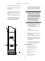
1.5 Inserting Fanfold Paper
The printer has a tractor which can handle fanfold paper of a minimum
width of 4 inch and a maximum width of 10 inch.
Getting started
Insert the smaller Exit Paper Guide (4) at the rear of the printer so that
the plastic hooks fit precisely inside the right and left edges of the paper
exit slot. The edge of this paper guide also serves as tear-off edge.
Ensure that the printer is placed on its printer stand (option) to guarantee
an optimal paper run. If you do not use the printer stand, align the printer
with the front edge of the table.
Depending on paper property, it would be helpful to use the printer
together with the OTC PC24 Stacker System (option).
The cables at the rear of the printer should not block the paper path.
Installation of Paper Guides
Use the delivered paper guides to ensure a straight paper path. The
paper guides are in the same box as the power cord.
Insert the larger Entry Paper Guide (3) into the front of the printer so that
the plastic hooks fit just inside the right and left edges of the paper entry
slot.
1-17
1-18
Getting started
Inserting paper for the first time or changing to another paper
width:
1. Open the top cover
2. Insert the paper into the slot at the front of the printer. Press and hold
the center button (36) on the front of the printer. The button releases
the paper rollers for paper insertion. Shift the paper into the slot until it
appears behind the OPC unit near the tractors. If you now release the
button the paper is kept by the rollers and your hands are free to
adjust the tractor.
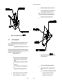
Getting started
3. Unlock the tractors (40) by moving the two green locking levers (42) to
their upright position.
4. Roughly adjust the tractors (40) to the paper width, and space out the
paper supports (43) evenly.
5. Open the tractor covers (41) and place the paper evenly on the pins.
Close the tractor covers (41). Be sure the top edge of the paper does
not extend the tractors.
6. Adjust the width of the tractors so that the paper is taut between the
tractors and secure the tractors using the locking levers (42).
Note:
1-19
1-20
The pins of the tractor (40) must be centered into the transport
punches of the paper.
Getting started
Getting started
1.6 Connection to the Computer
1.7 Connecting the Stacker System
Parallel
- Switch the printer and the computer OFF.
- Connect the interface cable coming from the computer to the printer's
parallel (33) or (serial (32) port, special option only).
As an option to the printer there is also an OTC PC24 Stacker System
available.
1-21
For installation please follow the instructions in Chapter 6. These
instructions also explain how to connect the stacker and the printer to the
mains.
1-22
Printer Operation
2 Printer Operation
2.1
2.1.2 Description of the LCD Display
The LCD Indicator gives information about the status of the printer.
In general you can distinguish the following messages:
- ONLINE messages
- OFFLINE messages
Control Panel
The control panel
- Gives information about the printer status
- Controls various parameter settings
- Allows manual control of the paper handling
When the printer is in the ONLINE mode the display shows:
O
N
L
I
N
E
(
n
)
2.1.1 Description of the Four Indicators
The 2-line Liquid Crystal Display (LCD) (89) indicates the current status
of the printer. If any error occurs (e.g. COVER OPEN), the resulting error
message will be displayed. While configuring, the printer menu settings
and parameters appear on the display.
The indicator READY (99) is lit, if the printer is supplied with power by
setting the power ON/OFF switch to ON or when an error no longer
occurs (e.g. the cover is closed).
The indicator DATA (90) is lit, if the buffer contains data. While data is
transmitted the display is flashing.
The green indicator in the field ONLINE (98) is lit when the printer is in
the ONLINE mode. Print jobs can be accepted and performed.
When the printer is in the OFFLINE mode status information, error
messages or menu messages can be displayed.
Status and error messages are displayed:
O
F
F
L
I
N
E
M
E
S
S
A
G
E
Example: The printer is warming up:
O
F
F
L
I
N
E
W
A
R
M
I
N
G
U
P
M
E
Menu messages are displayed:
O
F
F
L
I
N
E
M
E
S
S
A
G
E
N
U
Example: Display after pressing the MENU key:
2-1
O
F
F
L
I
N
E
P
R
I
N
T
I
N
2-2
M
G
E
N
U
M
E
N
U
Printer Operation
2.1.3 Function Keys
The function keys of the operator panel are grouped into two rows. The
function of the seven keys (91) to (97) depends on the printer operation
state.
97
Note:
2.2 Menu Mode
All operator selectable features are accessible via the control panel and
combined in the printer MENU.
This feature provides:
- Easy handling of configuration (language, etc.)
- Quick parameter changes
- Activation of test functions
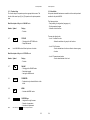
Short Description of Keys in the ONLINE mode
Number Symbol
Printer Operation
Display
- Function
The menu has three levels:
- Level 1 the Main Function
- Allows the selection of a group of sub functions
OFFLINE
- Changing to the OFFLINE mode
- Stops data transfer
- Level 2 Sub Functions
- Can be activated as a function or allows to choose a group
of values
In the ONLINE mode all other keys have no function.
Short Description of Keys in the OFFLINE mode
Number Symbol
- Level 3 Parameters and values
- Can be select/activate in this level
Display
- Function
97
ONLINE
- Changing to the ONLINE mode
- Starts data transfer
- Leaving the MENU-mode
91
FORMFEED
- Formfeed is only activated if data is in the
buffer
92
MENU
- Activates the MENU mode
93
CURSOR Keys
- Navigation through the menu
- Selection of parameters
- Activation of adjustments
Note:
The cursor keys
have an auto repeat function.
2-3
2-4
Printer Operation
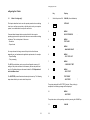
2.2.1 Activate the Menu
To activate the menu, please follow the next steps:
Printer Operation
In the last level to select/confirm values, the asterisk (*) to the right
indicates the actual selection.
By using the
or
key, you are able to change values.
- Press
The printer enters the OFFLINE mode
the display shows
MENU
Z MENU TEXT
*
OFFLINE
2.2.2 Confirm a new Selection
- Press
; the confirmed value is displayed with an asterisk (*) in the
last position as shown in the picture before.
- Press
the display shows
MENU
PRINTING MENU Y
Note:
All new values will be saved at once!
The Menu mode is left either by pressing the
or
key.
Selection of functions and parameters in one menu level:
Note:
- Press
or
; the keys have a wrap around function, i.e. after the
last value the first value is repeated.
On the display you will find the following characteristic messages:
MENU
MENU TEXT
Y
This is only displayed if you are in the Main Function. To switch the next
level, press
.
MENU
Z MENU TEXT
Y
Now you are in a Sub Function. Movement in both directions is possible
by using the
key or the
key.
2-5
2-6
The actual configuration can be printed with the function PRINT
TEST.
Printer Operation
2.3
OFFLINE
TONER LOW
Status and Error Messages
If the printer is powered on and ready to execute a print job, the following
messages can be displayed on the operator panel:
Displayed if toner has to be refilled (chapter 4).
This message can also be caused by a missing or badly installed
developer unit.
OFFLINE
COVER OPEN
ONLINE
POWER SAVE
Displayed if the top cover is open. After closing the cover, the printer
switches to the ONLINE mode.
The printer changes into this mode after a user defined period elapsed
without printing. In power save mode the printer switches off the fuser
heating, some fans and the motors. Power dissipation of the POWER
SAVE mode is less than 40 watt. With a new print job, the ONLINE
mode is resumed.
OFFLINE
PAPER JAM #
OFFLINE
WARMING UP
This message is displayed when the fuser unit of the printer is warming
up to the chosen temperature. When this temperature is reached the
printer switches to the ONLINE mode and starts printing, if data is in the
buffer.
This message will be displayed, if after a paper jam, the fanfold paper can
not be transported correctly. The number # gives an indication for the
place or cause of the paper jam:
0
Paper jam at paper entry of the fuser unit
1
Paper jam at the rear paper exit of the printer
2,3 Malfunction of the Top of Form sensor
4
Error with paper transportation in the tractor unit
5
Malfunction when opening or closing the fuser
6
Error with paper transportation in the fuser unit
The following messages are displayed if a condition exists which prevents
normal operation of the printer. The printer enters the OFFLINE mode.
Note:
OFFLINE
NO PAPER
Displayed if a print job is in process and the paper guide is running
empty.
2-7
2-8
In case of messages like NO DRUM UNIT ... see Chapter 5
Troubleshooting and Diagnostics.
Configuring the Printer
onfiguring the Printer
3.1
What is Configuring?
1.
This chapter describes how to use the operator panel and menu settings
to set up or configure your printer so that the printer, and your computer
system, can communicate correctly with each other.
Communication between the two requires that both the computer
operating system and the printer have the same communication settings
or features. The most important of those are:
- Emulation
- Paper format
The MENU mode allows you to access the configuration memory. All
settings of the printer are stored in this memory and can be printed out
on a list. Possible settings are discussed in detail in 3.3 Explanation of
Individual Menu Items.
The SELFTEST printout illustrates the actual printer set-up. The following
steps show which keys to use to start this printout.
Display
Switch the printer ON
ONLINE (after initialisation)
2.
OFFLINE
3.
MENU
SELECT PROFILE
6
MENU
TEST INFO
6
MENU
7 MACHINE COUNT
6
4.
5.
You may also need to change some of the printer's other features
depending on your hardware and application requirements, for example:
- Paper handling
- Text processing.
Key
6.
MENU
7 PCL TYPE LIST
7.
MENU
7 CONT SELF TEST
8.
MENU
7 SELF TEST
9.
TEST PRINT
7 SELFTEST
*
The printer starts with the SELFTEST printout. When printing is
completed, the following message will be displayed:
10.
MENU
7 SELFTEST
The printer returns to the operating mode after pressing the ONLINE key:
11.
3-1
3-2
ONLINE
Configuring the Printer
Configuring the Printer
3.2 Printout of Standard Configuration
The default configuration of the printer as defined in the factory, can be
recalled by the RECALL FACTORY function. This configuration is shown
on the following page.
The upper part of the SELFTEST printout shows the actual configuration
parameters. Main functions appear in the fist line of every menu block.
The second and following lines give information about the subfunction
and the selected parameters after the = sign.
Below the configuration parameters, a block of data gives information
about the firmware level of the printer.
The rest of the page is filled up with a diagonal test pattern.
The frame around the page is equal to the printable area of the actual
selected format. This is helpful to adjust a printout on the paper. The
frame of the default format A4 shows a pagelength of 11 2/3 inch
(297mm) and a image width of 8.25 inch (210 mm).
3-3
3-4
Configuring the Printer
RSTUVWXYZabcdefghijklmnopqrstuvwxyz0123456789!§ABCDEFGHIJKLMN
OPQRST
STUVWXYZabcdefghijklmnopqrstuvwxyz0123456789!§ABCDEFGHIJKLMNO
PQRSTU
TUVWXYZabcdefghijklmnopqrstuvwxyz0123456789!§ABCDEFGHIJKLMNOP
QRSTUV
UVWXYZabcdefghijklmnopqrstuvwxyz0123456789!§ABCDEFGHIJKLMNOPQ
RSTUVW
VWXYZabcdefghijklmnopqrstuvwxyz0123456789!§ABCDEFGHIJKLMNOPQR
STUVWX
WXYZabcdefghijklmnopqrstuvwxyz0123456789!§ABCDEFGHIJKLMNOPQRS
TTUVWX
XYZabcdefghijklmnopqrstuvwxyz0123456789!§ABCDEFGHIJKLMNOPQRST
TUVWXY
YZabcdefghijklmnopqrstuvwxyz0123456789!§ABCDEFGHIJKLMNOPQRSTT
UVWXYZ
Zabcdefghijklmnopqrstuvwxyz0123456789!§ABCDEFGHIJKLMNOPQRSTTU
VWXYZa
abcdefghijklmnopqrstuvwxyz0123456789!§ABCDEFGHIJKLMNOPQRSTTUV
WXYZab
bcdefghijklmnopqrstuvwxyz0123456789!§ABCDEFGHIJKLMNOPQRSTTUVW
XYZabc
cdefghijklmnopqrstuvwxyz0123456789!§ABCDEFGHIJKLMNOPQRSTTUVWX
YZabcd
ghijklmnopqrstuvwxyz0123456789!§ABCDEFGHIJKLMNOPQRSTTUVWXYZab
cdefgh
Configuring the Printer
3.3 Configuration Programs
The following programs for printer configuration are available:
- Profiler
A program for easy programming of all print job specific parameters
into Profiles.
- Profile Selector
For easy selection of one predefined profile.
Note:
Both programs are running under Windows 95/98 and NT 4.0
3.3.1
Installation
Follow standard procedures:
- For installation of the English version of the Profiler from the CD
select in the Windows Start Menu the function Run... and type the
command:
D:\profiler\install\usa\disk1\setup.exe
- For installation of the English version of the Profile Selector from the
CD select in the Start Menu the function Run... and type the
command:
D:\selector\install\usa\disk1\setup.exe
Note:
In both examples the letter D: is used for the CD-Rom drive.
After installation both programs are listed in the screen Programs of
the Windows Start Menu.
3-5
3-6
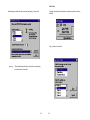
3.3.2
Profiler
In the Profiler the following menus are available:
- General Menu
- Paper Menu
- Emulations Menu
3.3 Configuration Programs
The following programs for printer configuration are available:
- Profiler
A program for easy programming of all print job specific parameters
into Profiles.
Note:
These three menus are available for all profiles.
- Profile Selector
For easy selection of one predefined profile.
General Menu:
Note:
Both programs are running under Windows 95/98 and NT 4.0
3.3.1
Installation
Follow standard procedures:
- For installation of the English version of the Profiler from the CD
select in the Windows Start Menu the function Run... and type the
command:
D:\profiler\install\usa\disk1\setup.exe
- For installation of the English version of the Profile Selector from
the CD select in the Start Menu the function Run... and type the
command:
D:\selector\install\usa\disk1\setup.exe
Note:
In both examples the letter D: is used for the CD-Rom drive.
After installation both programs are listed in the screen Programs of
the Windows Start Menu.
3-1
3-2
Already defined profiles can be saved, loaded for updating, and
downloaded into the printer:
Paper Menu:
Save Profile:
Emulations Menu:
Load Profile for updating:
3-3
3-4
Edit Profile:
Downloading of profiles into the printer and activating of one profile:
Copying of already defined profiles or resetting of profiles to factory
settings:
Copy of menus into profiles:
Warning:
All downloaded profiles will overwrite the corresponding
profiles stored in the printer!
3-5
3-6
- PAPER EXTENDED
With PAPER EXTENDED set the border areas ofA4 to NO. the
border areas of A4 and LETTER pages are not printable, conform
to the PCL5 definition. For compatibility to existing applications,
which use the border areas, PAPER EXTENDED can be set to
YES. The complete physical page is printable with unchanged
default cursor position.
With format, CUSTOM the complete page can always be printed
but the default cursor position is different to A4.
3.4 Explanation of Individual Menu Items
The menu of printers have the following main and subfunction to
configure the printer:
Main function PRINTING MENU
Within the Printing menu the layout of the print page is configurable.
- PAPER
A choice out of three different paper sizes can be made:
A4
LETTER
CUSTOM
If A4 or LETTER is selected the printer automatically sets all
parameters which define the allocation of the print image on a page.
Those parameter values are in accordance to the PCL5 definition.
- ORIENTATION
The orientation of the print image may either be PORTRAIT or
LANDSCAPE. The physical orientation of the print image is
influenced by the setting of LANDSCAPE MODE and
ORIENTATION MODE.
In case of A4 the contents of an A4 page is printed asymmetrically
onto a 12inch form which leads to a larger bottom margin than on
the top of A4.
In case of LETTER the page contents are printed onto an 11inch
form.
Note:
If the paper size is changed from one format into another the
printer selects the default values of the format describing
parameters (PAPER LENGTH, IMAGE WIDTH etc.) which
belong to the chosen paper size.
3-1
3-2
Note:
If the orientation is changed from one direction to another, the
page describing parameters (PAPER LENGTH, IMAGE
WIDTH etc.) are set to the corresponding default values.
Note:
If printing is performed in LANDSCAPE, and the selected
values for image width and line spacing don't lead to an
integer multiple of lines within this image area, the result will
be a displacement in the print image between two contiguous
pages. An evenly arranged print image can only be achieved
by either adapting the image width to the line spacing or by
selection of PERF.SKIP = ON.
- LANDSCAPE MODE
The orientation of the print image is influenced by this parameter.
Setting landscape mode to REVERSE rotates the image of
LANDSCAPE to REVERSE LANDSCAPE and REVERSE
LANDSCAPE to LANDSCAPE.
This makes successive pages with landscape orientation readable
like a book. Selection PCL COMPATIBLE is conformed to the
landscape orientation of Hewlett Packard printers.
- ORIENTATION MODE (ORIENT. MODE)
The Orientation Mode defines the print image rotation for CUSTOM
paper format. Setting the Orientation Mode to FIX (default)ensures
that the print orientation of a form with paper length, is shorter than
the image width, which is not rotated. It is printed in the same
orientation as with 12 inch length.
If the form length is shorter than the image width, Setting the
Orientation Mode to AUTOMATIC rotates the print image.. This
selection is necessary for applications which have PCL compatible
automatic rotation.
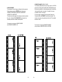
Print sample for configuring LANDSCAPE MODE
with ORIENTATION MODE = FIX
Print sample for configuring ORIENTATION MODE
with portrait and LANDSCAPE MODE = REVERSE:
3-3
3-4
- LINE SPACING
The distance between print lines is determined in lines/inch;
selectable values are: 1,2,3... 48 lines/inch. Default is 6 lines/inch.
The next menu items of the PRINTING MENU are only offered for
selection if the actual paper size is set to CUSTOM.
- PAPER LENGTH
The paper length can be selected in the range from 3 inch (76.2
mm) up to 20 inch (508.0 mm) in steps of 1/6 (4.23 mm) or 1/8 inch
(3.18 mm):
- LEFT MARGIN
This parameter defines the displacement of the first print position of
a print line from the left border of the printable area. Any value from
0 up to 999 positions can be selected; factory default value is 0.
- RIGHT MARGIN
The parameter value defines the distance of the last print position
within a line from the left border of the logical page. Any value in the
range from 0 up to 999 and MAXIMUM can be selected; factory
default is MAXIMUM.
Right Margin should only be set to a defined value if the application
requires a text formatting by the printer.
Note: Setting RIGHT MARGIN to a definite value in applications with
3; 3 1/8; 3 1/6; 3 1/4; 3 1/3; 3 3/8; 3 1/2; 3 5/8;
3 5/6; 3 3/4; 3 7/8; 4;..........12; .........20
down load Fonts or with rotation to landscape mode can cause data
loss of characters.
Note: If ORIENTATION = LANDSCAPE is selected the paper
length now corresponds to page width.
- TEXT LENGTH
The parameter defines the number of lines on a page; exceeding
this limit leads to a transition onto the next following page. Any
value from 0 up to 999 can be selected; factory default value is 72.
The parameter is ignored if PERF. SKIP = OFF was selected.
Note: In case of forms with paper length >
13.5 inch (345.45 mm)
the data buffer of 8 MB is not sufficient to ensure a
continuous printing. In those applications an additional
memory module of min. 4 MB must be inserted.
- IMAGE WIDTH
The width of the print image can be selected from min. 0.5 inch
(12.7 mm) up to max. 8.25 (209.55 mm) in steps of 0.05 inch (1.27
mm):
- PERFORATION SKIP (PERF. SKIP)
In case of PERF. SKIP = ON the printer takes the values of TOP
MARGIN and TEXT LENGTH into account on each page.
If PERF. SKIP = OFF is selected the printer prints over the
perforation. At the transition onto a next following page the values
of TOP MARGIN and TEXT LENGTH are ignored. Factory default
selection is OFF.
0.50; 0.55; 0.60; 0.65; .......8.20; 8.25
Note: If ORIENTATION = LANDSCAPE is selected the image width
now corresponds to page height.
- TOP MARGIN
This parameter defines the number of lines between the top paper
edge and the first print line. Any value from 0 up to 999 lines can be
chosen; factory default value is 0.
3-5
3-6
Main function PCL MENU
This menu defines the default parameters for the PCL emulation like PCL
typeface, character size, pitch and symbol set.
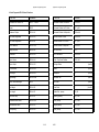
- SYMBOL SET
Symbol Set is a code table of characters and symbols.
Factory default is the ROMAN-8 symbol set. One of the following 31
different types can be set to be the standard in PCL.
Display
ROMAN-8
ISO L1
ISO L2
ISO L5
PC-8
PC-8 DN
PC-850
PC-852
PC-8 TK
WIN L1
WIN L2
WIN L5
DESKTOP
PS TEXT
VN INTL
VN US
MS PUBL
MATH-8
PS MATH
VN MATH
PI FONT
LEGAL
ISO-4
ISO-6
ISO-11
ISO-15
ISO-17
ISO-21
ISO-60
ISO-69
WIN 3.0
- FONT NUMBER
The font number selects one of the 54 PCL typefaces to the default
font within PCL emulation. A printout of the PCL TYPE LIST can be
started within the TEST MENU. Default is font No. 0 (COURIER)
- PITCH
Pitch defines the character size for FONT NUMBER 0, and 39 to
44. The value can be selected from 0.44 to 99.99 CPI.
Default is 10.00 character per inch.
- POINT SIZE
For FONT NUMBER 1 to 38 character scale is defined as point
size. The value can be selected from 4.00 to 999.75 PT in steps of
0.25.
Default is 12.00.
Note:
FONT NUMBER 45 to 54 are not scalable, the menu item PITCH or
POINT SIZE is not available.
3-7
3-8
Symbol Set
Roman-8
ISO 8859/1 Latin 1
ISO 8859/2 Latin 2
ISO 8859/5 Latin 5
PC-8 Code Page 437
PC-8 Danish/Norwegian
PC-850 Multilingual
PC-852 Latin 2
PC-Turkish
Windows 3.1 Latin 1
Windows 3.1 Latin 2
Windows 3.1 Latin 5
Desktop
PS text
Ventura International
Ventura US
Microsoft Publishing
Math-8
PS Math
Ventura Math
Pi Font
Legal
ISO United Kingdom
ISO US ASCII
ISO Swedish
ISO Italian
ISO Spanish
ISO German
ISO Norwegian
ISO French
Windows 3.0 Latin 1
ID number
8U
0N
2N
5N
10U
11U
12U
17U
9T
19U
9E
5T
7J
10J
13J
14J
6J
8M
5M
6M
15U
1U
1E
0U
0S
0I
2S
1G
0D
1F
9U
- FUSER TEMP.
This parameter allows to adjust the fuser temperature.
Default value is 185 °C, selection is possible from 165 °C to 185
°C in steps of 5 °C. Fuser temperature adjustment is necessary
when printing temperature sensitive formsets (labels).
Main function HEXDUMP MENU
The HEXDUMP MENU defines the execution of control sequences
when the HEXDUMP mode is activated.
- UEL COMMAND
Universal Exit Language commands can be set to RECOGNIZE
or IGNORE. That means this code can be executed in
HEXDUMP mode or the command is ignored and printed out as
hex code. UEL commands are parts of the Printer Job Language
(PJL).
- VERTICAL SHIFT (VER SHIFT)
- HORIZONTAL SHIFT (HOR SHIFT)
The parameters VER SHIFT and HOR SHIFT allow to precisely
position the print image vertically (+50...-16/100) and horizontally
(+50...-50/100). The adjustment can be done in steps of 1/100
inch (0.25 mm); factory default value of both parameters is zero.
Main function CONFIG MENU
Main function JOB MENU
Basic operation parameters for a print job are defined in the main
function JOB MENU.
- EMULATION
The Emulation determines the printer command code set.
Default emulation is PCL (PCL5E).
The function HEXDUMP is useful to analyse the data received by
the printer. Control codes are not carried out, instead all data
including comm and codes are printed out in hexadecimal format
and as ASCII characters. Any non-printable characters, such as
CR are only represented as a point (.) in the ASCII list.
- AUTOMATIC FORMFEED
If the print data does not fill a complete page or if there is no
Form Feed command (HEX 0C) at the end of a page this page is
not printed out. The page is staying in the printer memory if this
parameter is set to OFF. An incomplete page is automatically
printed after a selectable time period at the end of a print job.
(Pause in datastream) The time period can be set from 1 to 120
second.
Configuration menu includes subfunction to define the display language
and reset the printer.
- POWER SAVE
The time to enter the power save mode can be set to 15, 30, 45,
60 MIN or OFF. Factory default is 15 MIN. In power save mode
the printer switches off the fuser heating and fan. The message
POWER SAVE is displayed on the operator panel.
- PAPER SELECTION
Selecting the paper format (A4, LETTER, CUSTOM) with
software can be done with PCL or PJL commands. The
execution of this commands can be influenced by the parameter
PAPER SELECTION.
With PAPER SELECTION = IGNORE all software commands are
ignored and the format can only be modified with the operator
panel.
PAPER SELECTION = ONLY PJL means that PCL commands
are ignored. With PAPER SELECTION = RECOGNIZE all
software command are valid. This parameter is useful when
printing existing applications on different fanfold paper. (Letter
application on 12 inch)
Note:
3-9
3-10
PC24 WINDOW S printer driver use PCL and PJL commands.
- ENGINE ID
Only for service information.
- LANGUAGE
Selects the language of the display.
Default is ENGLISH available are:
ENGLISH, FRANCAIS, DEUTSCHE, ITALIANO, ESPANOL
Note:
- SELF TEST
This item is used to start the printout of the self test page with
the actual configuration and diagonal character test. (chap. 3.2)
Only in ENGLISH and GERMAN are all displayed messages fully
supported in the individual language.
- RECALL FACTORY
The factory default configuration can be recalled.
- CONT. SELF TEST
The self test page is printed continuously until any key is
pressed.
Note:
Main function for TEST MENU
- PCL TYPE LIST
By activating the PCL TYPE LIST a printout of all available PCL
Fonts is started, including information about the scalability and
corresponding font number.
TEST MENU is used to give life information of the printer and
consumables, and for starting test printouts. This includes the actual
printer configuration and PCL Font listing.
Note:
- MACHINE LIFE
This value is an indication for the printed pages of the print
engine. The counter is not modified when changing the control
unit.
- DRUM LIFE
This value is an indication for the printed pages of the OPC
drum. The counter is set to zero if an new OPC is inserted.
Note:
The printer does not stop immediately after pressing a key. The
prepared pages in the buffer will be printed before stop.
These pagecounters are incremented with every paper move of
11 inch; independent of move direction. The selected actual page
length is not calculated.
Example: A print job of 10 pages (A4) increments the counters
by 13. Printing a single A4 page increments the counter by 3
pages.
3-11
3-12
The PCL TYPE LIST gives helpful information when
programming different fonts and typefaces.
MENU
M en u-1
Maintenance
4 Maintenance
4.1
Filling in Toner
By the message "TONER EMPTY" in the display, the printer is indicating
that toner has to be added to the developer.
Installing the Parts of the Toner Kit
A Toner Kit comprises:
- Two Toner bottles (12), 8,000 pages each
- One spout (13)
- Two Waste Toner Containers (14)
- Two Cleaner Felts (15)
Only toner that has been released for the printer must be used. This toner
is part of the before mentioned Toner Kit
The toner will do for about 16,000 pages based upon a density of 5% per
page.
Shake the bottle (12) several times to mix the toner well. Open the cover
of the Developer Unit (28) to its upright position. Carefully open the seal
underneath the cap of the toner bottle and attach the spout to the bottle.
Spread the toner evenly across the opening of the Developer Unit.
Note:
Note:
Save the box and all packing material of the Toner Kit!
Please, help to protect the environment and make use of the
recycling program that is offered to you!
In the Toner Kit box there is a label which explains how to treat the
used parts.
4-1
4-2
Do not squeeze the toner bottle since the toner could be blown
out of the hopper and contaminate the printer. If the toner bottle is
not completely empty, gently tap the end of the bottle while
holding it upside down over the hopper.
Maintenance
Maintenance
Replacing the Waste Toner Container
In case the Waste Toner Container is already filled considerably, it is
advised to replace it.
First lift the OPC Drum out of the printer and carefully set it aside on a
clean surface.
Note:
Do not touch the green part of the OPC Drum with your fingers.
Oil and dirt will degrade print quality.
Do not expose the light-sensitive OPC Drum to room lighting or
sunlight any longer than necessary.
Now, remove the old Waste Toner Container from its compartment which
is close to the Developer Unit. Close the filling hole with the green cap.
Take care that the cap fits tightly over the opening.
When shipped, two Waste Toner Containers (14) are in the box of the
Toner Kit. Take one of them and put it into the compartment. Please
observe that the green cap is placed on the cap holder and not over the
filling hole.
Close the top cover of the Developer Unit (28). If you hear a "click" the
shutter is completely closed.
4-3
4-4
Maintenance
Maintenance
Changing the Cleaner Felt
If toner is refilled you should also check the status of the Cleaner Felt.
The Cleaner Felt is below the cover of the fuser unit at the rear of the
printer.
If the Cleaner Felt is very dirty, you have to replace it. A new Cleaner Felt
(15) is in the box of the Toner Kit. Insert it below the top cover of the
Fuser Unit at the rear of the printer. After inserting the felt, the top cover
does not lock completely. Don't worry about this, the printer top cover will
provide the necessary pressure to keep the Cleaner Felt cover tight.
Carefully place the OPC Drum (11) back into the printer and by slightly
pressing make sure that it is fully seated. The opening for toner waste is
now just over Waste Toner Container (14).
Note:
4-5
4-6
Depending on the used paper type it may be necessary to change
the Cleaner Felt more often.
Maintenance
4.2
Replacement of the OPC Drum
Maintenance
Note:
If the print quality gets worse or as a preventive measure after printing
about 30,000 pages the OPC Drum (11) should be replaced. The display
indicates this status by the message "EXCHANGE DRUM". This message
is considered to being a warning. Although the user is free to continue
printing, before every new print job, the message will be displayed again.
Please do not touch the green part of the OPC Drum with your
fingers. Oil and dirt degrade print quality.
Do not expose the light-sensitive OPC Drum to room lighting or
sunlight any longer than necessary.
It is only allowed to use an OPC Drum that has been released for the
printer..
1. Open the top cover of the printer.
2. Remove the old OPC Drum carefully from the printer and set it aside
on a clean surface.
3. Remove the paper from the printer.
4. Clean the inside of the printer with the cleaning pads which are in the
box of the Cleaning Kit and pay special attention to the "Corona" wire
below the OPC Drum. Clean it with the brush which is also in the box of
the Cleaning Kit.
The OPC Drum is very light-sensitive, so it is wrapped up in lightproof foil.
Carefully remove the drum from its foil container.
Insert the new OPC Drum into the printer behind the Developer Unit.
Gently press the top of the OPC unit to make sure it is fully down. The
opening for toner waste is now over the Waste Toner Container (14).
Note:
4-7
4-8
Please contact your delivery agent for the recycling program of
OPC Drums!
Maintenance
4.3
Replacement of the Developer Unit
To guarantee a good print quality you have to replace the Developer Unit
after having printed about 100,000 pages.
You must only use a Developer Unit which has been released for the
printer.
Maintenance
Gently lift the plastic tabs inside the printer, at the left and at the right side
of the cover, and pull the front cover (23) in forward direction. The front
cover will only open to a 45 degree angle. Please do not force this cover
beyond a 45 degree angle.
Move the two green locking levers at the right and left of the Developer
Unit to their upright position. Pull the Developer Unit out of the printer.
The Developer Unit is part of the "Developer Kit" which consists of:
-
The Developer Unit (6)
One Ozone Filter (7)
One bottle with Starter Toner (8)
One spout (9)
One Cleaning Kit (10)
4-9
4-10
Maintenance
Slide the new Developer Unit fully into the printer along the plastic rails on
the left and right. To lock push down the two green plastic levers.
Maintenance
Note:
Do not squeeze the toner bottle since the toner could be blown out
of the hopper and contaminate the printer. If the toner bottle does
not completely empty, gently tap the end of the bottle while holding it
upside down over the hopper.
This first filling only allows Starter Toner to be used. Refilling any other
toner is not allowed before the message "TONER EMPTY" appears on
the display.
Filling in Starter Toner
Before using the Developer Unit for the first time, you have to fill it with
Starter Toner. One bottle Starter Toner (8) with a spout (9) is in the box of
the Developer Unit. Shake the bottle several times to mix the carrier and
the toner. Carefully open the seal underneath the cap of the toner bottle
and attach the spout to the bottle. Spread the toner evenly across the
opening of the Developer Unit.
Close the top cover of the Developer Unit. If you hear a "click" the shutter
is completely closed
.
4-11
4-12
Maintenance
Inserting the Ozone Filter
When replacing the Developer Unit you should also replace the Ozone
Filter. The box of the Developer Unit also contains an Ozone Filter (7), a
black rectangular block. At one of the short sides there is a small tab to
hold the filter. Insert the Ozone Filter into the slot immediately behind the
operator panel and besides the Developer Unit.
Maintenance
4.4
Replacement of the Fuser Unit
The Fuser Unit has a lifetime of approximately 300,000 pages.
To check the lifetime of the Fuser Unit the page count should be written to
a log manual every time a Fuser Unit has been changed.
Replacement of the Fuser Unit should only be performed by a Service
Technician.
Firmly close the front cover (23).
Note:
Please contact your delivery agent for the recycling program of
Developer Units.
4-13
4-14
Maintenance
4.5 Exchanging the Control Unit
When shipped, the Control Unit (30) is already installed in the printer.
Maintenance
The picture below shows the optional version of the Control Unit which is
equipped with a serial (33) and parallel (32) interface. For detailed
information about your CU see Chapter 2.
If your host system requires, it might be necessary to exchange the
Control Unit (CU); this can easily be done:
The Control Unit is accessible at the rear of the printer. Loosen the two
green lock screws and pull the Control Unit out of the printer. Insert the
new Control Unit into the mounting rails until the connector fully engages.
Hand tighten the two lock screws (31).
Note:
4-15
4-16
-
To avoid damage due to electrostatic discharge, do not touch
the connector pins or components of the CU.
-
Never attempt to install or remove a CU while the printer is
switched ON.
Troubleshooting and Diagnostics
5 Troubleshooting and Diagnostics
5.1
Power-related Problems
Display elements are not lit when power is switched On
- Check that the power cord and plug are securely fitted to the printer
and to an electrical outlet. If the printer is equipped with the OTC
Paper Stacker, the power for the stacker is supplied seperately.
(See chapter 6)
- Ask for the power connector connections (and fuse, if fitted) to be
verified.
- Ask for the building electrical supply to be verified.
How to Use This Section
1. Find the category in which your problem occurs. The problem
categories are:
- Power-related Problems
- Error Messages
2. Find the description that most closely matches the printer symptom.
5.2 Error Messages
After selftest, the printer enters the ONLINE mode.
In case of a failure following messages may be shown on the display:
3. Try the first suggestion under that heading.
4. If the suggestions above continue to keep you from printing, or if the
fault is not listed, contact your service.
OFFLINE
CHK TONER BOTTLE
Every time the printer is switched ON an internal selftest is started.
The actual version of the "Bootstrap" software is displayed:
PC24 BOOTSTRAP
REVISION X.XX
The Waste Toner Bottle is not correctly mounted or missing.
Note:
After that the memory is tested:
MEMORY TEST
PLEASE WAIT...
The waste toner level inside the bottle is not controlled. The user
has to check the waste toner bottle every time when refilling new
toner.
OFFLINE
NO DRUM
If memory test is completed successfully the Operating System is started:
INITIAL TEST OK
STARTING PPOS...
The OPC drum is not correctly mounted or missing.
OFFLINE
SERVICE FUSER N
After initialzation the printer enters the normal operation mode:
The mechanics of the Fuser base is not working incorrectly. The
parameter N gives more detailed information:
N=0
Malfunction when opening or closing the fuser rollers.
N=1
Malfunction when opening or closing the fuser rollers.
N=2
Malfunction of sensors at the speed control plate.
ONLINE
If an error message is displayed please refer to the following section.
All other messages are described in section 2.3 Status and Error
Messages.
5-1
5-2
Troubleshooting and Diagnostics
OFFLINE
SERVICE HEATER N
The heater of the fuser unit is not working correctly. The parameter N
gives more detailed information:
N=0
Indication of thermistor has a broken wire.
N=1
Indication for thermistor is short or has an extraordinarily high
temperature.
N=2
Defect heating, warm up not completed within specified time.
N=3
Defect heating, not keeping temperature during print.
OFFLINE
SERVICE LSU N
There is no correct function of the Laser Scanning Unit. The parameter N
gives more detailed information:
N=0
No laser beam detected.
N=1
No locking signal of Pase Lock Circuit.
N=2
Phase Lock Circuit lost syncronization.
N=3
Malfunction of LSU motor control.
OFFLINE
SERVICE EEPROM
Check sum error of EEPROM.
OFFLINE
SERVICE VSYNC
Error in synchronization of paper transport system.
ONLINE
ENGINE LIFE
This message indicates that the engine has printed 3.000.000 pages.
This is the maximum page count for the engine. Please contact your
service partner.
The printer has to be refurbished due to general wear out of the engine.
5-3
PrintCenter24 Paper Stacker
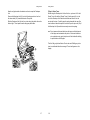
6. PrintCenter24 Floor Model Paper Stacker
6.1 Assembling the PrintCenter24 Stacker
6.1.1 Unpacking & Installation
You will need a utility knife for unpacking the container and a
small, flat-blade screwdriver to fasten cable connectors.
Inspect shipping container for damage. Report damage to
1.
carrier immediately.
Stand shipping container upright.
2.
Use a utility knife to remove one side of the container.
3.
See Caution below, then move contents to installation site.
4.
! CAUTION !
If you use a lift truck, only lift along bottom rails of the
stacker. Do not use a lift truck after plastic strap has been
removed.
5.
Remove plastic stretch wrap.
Remove accessories box. Also, remove bubble package
6.
resting on refolding deck. Check contents of box and
package against the following illustration.
Cut plastic strap holding cardboard pad to bottom of deck.
7.
Use the screwdriver provided to remove two screws (with
8.
nylon washers) holding printer stand to refolding deck. Lift
off stand and then re-install screws and washers to deck.
9.
Lift refolding deck off cardboard pad. Save all packing
materials.
See also section 6.4 Pa per Motion S ensor.
Note: UL/CSA, 120 vac, plug-in power supply is shown here. A 230 vac, in-line
power supply is available.
6-1
6-2
PrintCenter24 Paper Stacker
PrintCenter24 Paper Stacker
Tilt this assembly and screw in floor glides near the ends
6.1.2 Assembly
1.
6.
and middle of the rails. Adjust the glides so that the
stacker is stable.
Move refolding deck and printer stand onto a hard, flat
surface.
Position U-channels of printer stand rails just opposite
Note: An optional set of six casters can be used in place of
the floor glides.
2.
open rails of refolding deck, as shown in the next
illustration.
Place the stacker in position and then place the printer on
7.
the printer stand. Also, check to see that the front of the
printer is parallel to the front edge of the stand.
Note: It is possible to install the deck backwards. Make
sure you orient the deck, as shown in the illustration,
so that the corner of the deck with the manual mode
switch is located nearest the printer stand.
The feet on the printer must rest in the indentations provided in
the stand.
Insert channels of printer stand into rails of refolding deck
3.
a. Pivot the paper chute slightly and then lift the free end of
the pivot arm, which is attached to the paper chute, and
insert it into slotted bracket on printer, as shown in the
next illustration.
so that two pairs of screw holes line up. (It may be
necessary to temporarily loosen the four screws that
secure the refolding deck to its rails.)
Secure the two halves of the stacker with the screwdriver
4.
and four, 3/8-in.-long Phillips screws provided in the
accessory box.
If necessary, retighten screws to resecure deck to its rails.
5.
b. Slowly open top cover of printer to check that this paper
chute assembly is securely in place.
6-3
6-4
PrintCenter24 Paper Stacker
PrintCenter24 Paper Stacker
See Caution and Note below before installing control
230 vac at 50Hz (or your
receptacle is other than
a NEMA 5-15 or a CEE
7/7, as shown in the
following illustration),
you will need to
purchase a class 2,
regulated 12
vdc, power supply. The
power supply must be
capable of supplying 12
vdc at a minimum of
800 ma to the stacker
via the type of connector
shown in the following
illustration.
8.
cable, as follows:
! CAUTION !
Your printer requires a paper motion sensor for automatic
operation. See section 6.4
a. Connect the 9-pin end of the control cable to the
D-shaped, 9-pin control connector on the refolding deck
b. Tighten screws on both connectors to secure cable.
c. Make sure manual mode switch on refolding deck is off,
as shown in the illustration on Page 12.
9.
9.
Insert connector on power supply cable into receptacle on
refolding deck. Connect power supply to a suitable receptacle.
10.
If desired, use supplied
cable ties to fasten
control and power
cables to legs of stacker
11.
Test manual mode by toggling the manual mode switch on the
refolding deck.
Both pairs of refolding coils should turn.
12.
Test automatic mode for a PrintCenter24 printer, as follows:
Turn on PrintCenter24 printer.
a.
If your power source is other than 120 vac at 60Hz or
6-5
6-6
PrintCenter24 Paper Stacker
PrintCenter24 Paper Stacker
Print a one-page print job.1
b.
When the PrintCenter24 printer begins to print it will start
the stacker. The stacker will stop when the PrintCenter24
printer stops printing. If it doesn’t start and stop
automatically, you may need to install a paper motion
sensor for automatic operation. See Parts & Accessories,
Page 26.
Slip the main paper guide onto the paper stack support, as
13.
shown in the following illustration.
Slide this assembly, the paper stacker, between support
14.
channels on refolding deck.
NOTE: The paper stacker assembly may be installed for
either right- or left-side access, whatever’s convenient.
1
For example, to print a summary
page, be sure the printer is off line,
then press the MENU key. After the
printer displays “Print: Summary,”
press STORE to print.
6-7
6-8
PrintCenter24 Paper Stacker
PrintCenter24 Paper Stacker
6.2 Operating the PrintCenter24 Paper Stacker
5.
1.
Adjust position of paper stacker so that the face of the
main paper guide is approximately at edge of paper.
2.
Now slide refolding units so that indicator marks at
bottom of units point to the proper perf-to-perf form length
marked on the deck.
The refolding units are mounted on a rack and pinion
Make sure that the paper will stack on the stacker in the
same way it is in the box. To do this, mark an “X” on one
of the horizontal out-fold perfs at the paper entrance to
the printer, as shown in the following “Before” illustration,
and then use the printer’s control panel to form feed that
fold through the printer.
mechanism so that they move as a unit. When you
adjust one, the other automatically adjusts to the same
complementary position.
NOTE: The positioning of the refolding units is critical for
fault-free performance.
3.
Check that the four coils are at the bottom of their risers.
The top caps of the risers
contain two plastic barbs to
capture the coils and suspend
them so that you can easily
remove the print job.
NOTE: The positioning of the
refolding units is critical for
fault-free performance.
6.
At output of printer, make sure that paper feeds through
paper chute and then close the bail.
Again, use the printer’s control panel to advance the
7.
paper. Continue until out-fold perf with mark is at bottom
of stacker.
4.
Open bail of paper chute.
6-9
6-10
PrintCenter24 Paper Stacker
PrintCenter24 Paper Stacker
Make sure the mark you made at the out-fold perf is not
11.
8.
lapped over, as would be the case of an in-fold perf. (See
the “After” illustration.)
9.
Adjust paper stacker, if necessary, so that paper falls in a
straight cascade from the paper chute to bottom of
stacker.
The paper should be centered between the two pairs of
If necessary, re-adjust paper stacker and/or refolding unit.
The paper should not drag or hang up on sheet-metal
paper guide(s), especially when you just begin a stack.
Note: Starting the stack 1/8 in. from the guides is
important if you plan on a tall stack, and
especially when using lower-quality paper.
The perfs of some fanfolded paper are not
always squared well with each other and so,
as the stack grows, it may tend to lean a
little. If this causes a problem, we
recommend a different brand of paper1 .
coils. Stacking works best if the paper stack is started
about 1/8 in. (approximately 3 mm) from the paper
guide(s), as shown in the following illustration.
12.
When print job is done and you wish to retrieve your
printing, advance the last printed page past the paper
chute and then separate at the perf.
If you used the auxiliary paper guide, slide it out of the
13.
deck channels.
Lift the refolding coils to the tops of their risers.
14.
15.
Use the handles on the paper stack support to slide out
and transport the print job.
Don’t use the flexible platform attached to the wedge of
the paper stacker for carrying the print job. If you do, you
might spill the paper stack. Use the built-in handles on
the paper stack support.
16.
1
After removing the stack of paper, don’t forget to release
the coils so that they’re ready for the next job.
If stack-lean interferes with unattended performance,
check for bad perforation alignment. To test for
perforation misalignment, turn the box of paper around
on the next print job and check if the stack tends to lean
in the opposite direction. If it
does, change brand names. We recommend our own
brand of paper (Part No.
LM1000C112) which is manufactured to exacting
10.
Begin printing.
tolerances for consistent performance.
6-11
6-12
PrintCenter24 Paper Stacker
PrintCenter24 Paper Stacker
The PrintCenter24 Floor Model Stacker will hold more
6.4 Paper Motion Sensor
than the tallest box of continuous form paper. If you
happen to overfill the stacker with paper from more than
one box, the coils will compress at the top of their risers.
Although this won’t harm the stacker, you may find it
inconvenient when removing the print job. If you
compress the coils to their limits, the rest of the print job
will not stack properly.
6.4.1
Installation
The paper motion sensor attaches to the underside of the paper
chute support. To install —
1.
2.
Turn off printer. Also, make sure the refolding stacker
is off.
If necessary, position the encoder wheel in the middle
of its axle, as shown in Figure 1, and then snap the
axle into place with paper motion sensor housing.
6.3 Troubleshooting
The PrintCenter24 Floor Model Stacker is lubricated for life. Do
not lubricate in any way.
6.3.1 When it doesn’t runCheck the power supply and control cable.
6.3.2 When Only one pair of coils turnsOne of the two motors has failed. Call one of the voice
or fax phone numbers listed on the back of the title page
of the PrintCenter24 Stacker Manual.
6.3.3 When it Doesn’t Stack Right! Check that the paper falls in a straight line from the
printer to the stacker. Make sure the paper stack
support is directly below and centered with the paper
chute.
! In general, the stack should be centered front-to-rear
and side-to-side among the four coils.
! Check that the paper is not being refolded in the wrong
way. It should stack on the stacker like it was in the box.
! Use a better grade paper.
Figure 1. Paper Motion Sensor
3.
Slip paper motion sensor housing over the two
threaded studs on the underside of the paper chute
support, as shown in Figure 2.
Loosely secure one side of housing with one of the
4.
nuts provided.
Place green ground wire connector on the other stud
5.
and loosely secure with nut.
6.
6-13
6-14
Plug control cable connector into the paper motion
sensor.
PrintCenter24 Paper Stacker
PrintCenter24 Paper Stacker
6.4.2
7.
Make sure the sensor wheel rotates freely in the slot of
the paper chute support, and then tighten nuts with
wrench provided.
Connect the 9-pin end of the sensor cable to the D-
Cleaning the Sensor
The paper motion sensor uses an infrared light emitter and
detector to sense the rotation of the encoder wheel.
If dirt or paper dust clogs the holes in the wheel, or if the emitter
8.
9.
shaped connector on the refolding deck and then
secure the two Phillips head connector screws.
or detector window of the sensor becomes obscured, the
refolding stacker may fail to start when paper from the printer
turns the encoder wheel.
Test as follows.
Turn stacker on and then off to ensure stacker is ready
To clean the paper motion sensor, proceed as follows:
Turn off power to the refolding stacker by
for operation. Make sure stacker is off and then turn on
printer. Make sure the printer is on line and then send a
print job, such as a PrintCenter24 summary page.
(There’s no need to turn on the refolding stacker
because the paper motion sensor will do this for you.)
Approximately
2 seconds after paper stops moving, the refolding
stacker stops.
Figure 2. Paper Motion Sensor Installation
1.
unplugging its power supply.
Remove the housing of the paper motion sensor
2.
from the bottom of the paper chute.
See Figure 2.
Remove the encoder wheel by lifting its axle
3.
from the cradle slots in the housing. See Figure
3.
Check and, if necessary, clean out the holes in
4.
the wheel.
Use 90% isopropyl alcohol (or a
5.
diskette/recording head cleaner) and a lint-free
swab or cloth to clean the sensor’s emitter and
detector windows which are located near the
inside tips of the U-shaped sensor.
6.
Re-position the encoder wheel on its axle and
then snap the axle into place on the housing.
Make sure the wheel is between the two tips of
the optical sensor.
Note: Only the wheel turns. The axle doesn’t.
Resecure the paper motion housing to the
7.
underside of the paper chute and then test its
operation with the refolding stacker.
(Underside View of Paper Chute Support)
6-15
6-16
PrintCenter24 Paper Stacker
PrintCenter24 Paper Stacker
Remove the jumper connected to one pin of
3.
JP1 on the paper motion PCB. See Figure 4.
Install the jumper across both JP1 pins.
4.
Figure 4. Paper Motion Sensitivity Adjustment
Remove the encoder wheel so that no
5.
Figure 3. Paper Motion Sensor (Inside View)
6.4.3
Sensitivity Adjustment
The paper motion sensor is set at the factory so that,
when the encoder wheel rotates, the sensor will turn on the
refolding stacker.
If the paper motion sensor fails to turn on the
stacker, try cleaning the encoder wheel and sensor windows, as
described in the preceding paragraphs. If necessary, adjust the
sensitivity of the optical sensor, as follows:.
Make sure that the —
1.
obstruction blocks the gap between the halves
of the optical sensor.
! Paper motor sensor cable is interconnected
between the sensor housing and refolding
stacker,
Refolding stacker is connected to its power
!
source, and
The override switch on the refolding deck is
!
switched off so that the coils don’t rotate.
Use a very small, flat-tipped screwdriver to
6.
adjust potentiometer R3 on the paper motion
PCB:
If the LED (DS1) is illuminated, turn the R3
!
adjustment clockwise until the LED
extinguishes. Slowly turn the R3
Detach the paper motion sensor unit from the
2.
bottom of the paper chute. See Figure 2.
6-17
6-18
PrintCenter24 Paper Stacker
!
PrintCenter24 Paper Stacker
adjustment counter-clockwise until DS1
just illuminates.
If the LED (DS1) is extinguished, turn the
R3 adjustment slowly counter-clockwise
until DS1 just illuminates.
Remove the jumper and re-install it on either
7.
one of the JP1 pins.
Re-install the encoder wheel into the sensor
8.
assembly.
Re-install the unit to the paper chute.
9.
6.4.5
Replacement Parts
To order a field replaceable part, proceed as follows:
1.
Fig
ur
e
Find the appropriate part number on Figures 5a
and 5b.
5a. Paper Motion Sensor
(Illustrated Parts Breakdown)
Figure 5b. Control Cable Assembly
6-19
6-20
PrintCenter24 Paper Stacker
(020-00197-XX)
2.
Obtain the serial number of your stacker (along rim of
refolding deck).
3.
If applicable, have your Visa or MasterCard
number and expiration date ready, and then contact
Output Technology Corporation by phone, fax, or mail:
3808 N.Sullivan Rd. Bldg#3
Spokane, WA 99216
Phone: (509) 536-0468
Fax: (509) 533-1280
6-21
Technical Data
7.
Technical D ata
Warm-up Time / Beginning to Print
# 3 min from ambient temperature
After # 20 s at operating temperature
After # 30 s from stand-by
The technical data specified in this chapter are applicable to a printer
equipped with a control unit that supports the serial and parallel interface.
7.1
Printer Specification
Print Technology
- Electrophotographic with diode laser
- Organic photoconductor (OPC) drum
- 1 1/2 component toner/developer system
- Heat and pressure fusing with adjustable fusing temperature
Fuser Control Modes
- Operating:
The printer keeps the fuser at fusing temperature
which is in the range of 165°C to 185°C.
- Stand-by:
The printer keeps the fuser at stand-by temperature,
at approx. 165°C.
- Idle:
The printer lets the fuser cool to almost ambient
temperature by turning the fuser off.
Dimensions
460 mm x 248 mm x 498 mm (W x H x D)
Paper Transport
- Plain, straight-through paper path
- Adjustable, retractable tractor with auto-centering
- Paper top-edge detection
- No forms waste if last printed page is not torn off
Weight
25.5 kg incl. consumables
22.0 kg no consumables
Mains Voltage
220 - 240 V AC, 50 Hz
Print Image Area
Max. width 8.25 inch (210 mm)
Min. length 3 inch (76.2 mm)
Max. length 33 inch (838.2 mm)
Power Dissipation
- Operating:
< 1.000 W
- Stand-by:
< 300 W
- Idle:
# 40 W
Resolution
300 x 300 dpi
Environmental Conditions
- Operating:
10 to 32.5°C, 20 to 80% rel. humidity
- Storage:
-30 to 60°C, 10 to 95% rel. humidity
Process Speed
4.4 inch/s (112.23 mm/s)
Noise Level
(Based upon ISO 7779 at the bystander position)
- Operating:
# 53 dB(A)
- Stand-by:
# 47 dB(A)
Print Speed
24 pages per minute (ppm) at 11 inch page length
7-1
7-2
Technical Data
Duty Cycle / Reliability
- Duty cucle:
up to 50,000 pages per month
- Lifetime:
3,000,000 pages
- MPBF:
300,000 pages (depends on usage)
- MTTR:
< 45 min
Approvals
- TÜV/GS
- CE
7.2
Technical Data
7.3
Connectivity
Interfaces
- IEEE 1284 Type B parallel
- Connector to OTC Stacker System
- Further interfaces with optional Control Units:
- Centronics parallel with IGP emulation
- Serial RS-232/V24 with IGP emulation
- Ethernet 10Base2 and 10BaseT
EN 60950, EN 60825
EN 55022 Class B, EN 50082-1
Processor
AMD 29240 32 Bit RISC Processor
Paper Specification
- Type:
Continuous form fanfold or roll media with 0.5 inch
tractor feed pin holes
Buffer
8 MB standard, optionally expandable
- Weight:
56 g/m2 - 90 g/m2
optimal 68 g/m2 - 75 g/m2
- Caliper:
0.08 - 0.2 :m
Emulations/ Page Description Languages
- HP LaserJet 4 (PCL 5e)
- HP-GL/2
- IGP 10-20-40 with optinal Control Unit
- Smoothness:
100 - 180 Sheffield or 20 -Bekk
100 - 250 Sheffield for labels
- Width:
Min. 4 inch (101.6 mm) edge to edge,
3.5 inch (88.9 mm) pin to pin
Fonts
- 45 scalable fonts
- 6 bitmap fonts with fix pitch 16.67 CPI
- OCR-A and OCR-B
- 2 Barcode fonts Code 39
Max. 10 inch (254 mm) edge to edge,
9.5 inch (241.3 mm) pin to pin
- Form Length:
Min. 3 inch (76.2 mm)
Max. 33 inch (838.2 mm)
in increments of 1/6 or 1/8 inch
- Shelf Life:
1 year at min. 22°C and 50% rel. humidity
Barcode
- Code 39
- 2 of 5 industrial
- 2 of 5 interleave
- EAN 8 and EAN 13
- UPC-A and UPC-E
- Codabar
- MSI
- Code 93
- Postnet
- Code 128
7-3
7-4
Technical Data
7.4
Consumables
Technical Data
7.5
Specification of the OTC Floor Model Stacker
Toner Kit
16.000 pages at 5% density
Contains two of each:
- Bottle Toner
- Waste Toner Container
- Cleaner Felts
Width
20 in. (approx. 508 mm)
OPC Kit
- OPC drum
Height
30 in. (approx. 762 mm)
Length
37 in. (approx. 940 mm)
30,000 pages
Developer Kit
100,000 pages
Contains
- One Developer Unit
- One Ozone Filter
- One bottle Starter Toner (200g Toner, 40g Carrier)
- One Cleaning Kit
Shipping Dimensions
22 x 26 x 33 in. (Approx. 560 x 660 x 840 mm)
Shipping Weight
43 lb (approx. 25 kg)
Power Supply
12 vdc at 800 ma. One of two power supplies is shipped with the stacker:
either a UL/CSA, 120 vac, 60Hz, plug-in power supply, or a 230 vac,
50Hz, in-line power supply with a TÜV power cord
Fuser Unit
300,000 pages
The Fuser Unit should be exchanged by a Service Technician.
Note:
The previously mentioned number of pages is based upon
xerographic quality paper with 9.5 inch x 11 inch size and 75 g/m2
paper weight.
Power Consumption
Not more than 10 w
Storage of consumables is possible for 18 months from date of
manufacture. For shipping or storage of consumables the
following environmental conditions have to be met:
-10°C to 40°C
10% to 90% rel. humidity.
7.6 Paper/Label Requirements for the OTC Floor Model Stacker
7-5
7-6
Technical Data
Paper Type
Fanfold, single-part paper with a bond weight of 18 to 24 lb (65 to g/m2)
and a caliper thickness of 3.2 to 4.5 mil (0.081 to 0.0114 mm.) Prefer 24
lb paper without laser (clear perf) perforations.
Label Type
Fanfold labels with a caliper (thickness) not to exceed 7.5 mil (0.190 mm)
Sheet Lengths
Variable from 6 to 14 in (approx. 152 to 355 mm), perf to perf
Sheet Widths
Variable from 4 to 10 in (approx. 101 to 254 mm) including ½ in. tractor
strips
Stack Limit
Up to 15 in. (approx. 380 mm) in height or about 2000 sheets of 24 lb
bond paper
7-7
Appendix A Programming Guide
Appendix A Programming Guide
Conventions
The printer matches the Hewlett-Packard ® Company’s LaserJet 4 Plus
printer. In addition it includes some features not available with the
LaserJet 4 printer.
Please note, that some PJL features are not supported by the printer.
The following conventions are used in the command listings:
S
S
S
Support for additional paper sizes
To make use of arbitrary paper sizes of fanfold paper the printer
supports the paper format CUSTOM. This enables the user to define
PAGELENGTH and IMAGE WIDTH separately by means of PJL
sequences.
The paper format CUSTOM can be selected by a PCL5 or PJL
sequence.
Additional Printer Job Language (PJL) commands
In order to set PAGELENGTH and IMAGE WIDTH of fanfold paper,
associated parameters have been added to the printer’s environment
to be selected by the SET and DEFAULT command in a PJL
sequence.
20 different resident Barcodes
A variety of barcodes can be selected by additional PCL sequences,
to be printed in various sizes and orientations.
Spaces may appear between characters in sequence for
clarity; they are not part of the format. A Space character is
indicated by the grafik symbol 8 .
ESC
Escape (1/B), introduces an escape sequence
@
Introduce a PJL command
P1
Numeric parameter, or number of units that specify a distance
or quantity pertaining to the escape sequence, control function
or control string. Accepted values are 0...9999.
If the parameter is in normal notation like "200" the
programming in hex-code is according to a ASCII table. ("200"
= 32,30,30 in hex).
8
Grafik symbol used for Space (hex 20)
<CR>
Carriage Return
<LF>
Line Feed
The features described below refer to the Firmware Revision V1.20 of
the printer.
Note:
For more information regarding PCL5 and PJL programming
please refer to the
- PCL5 Printer Language Technical Reference Manual (5961-
0509)
- PJL Printer Job Language (5961-0704)
published by Hewlett-Packard ® Corporation.
A-1
A-2
Appendix A Programming Guide
1
Appendix A Programming Guide
2
PCL5 Extensions for Paper Size Selection
2.1
Escape Sequence
Function
Parameter
ESC & l P1 A
1B 26 6C P1 41
Page Size
P1 =
2
P1 = 26
P1 = 101
S
PJL Extensions
Basic Rules for PJL Programming
To change from PCL to PJL, enter the Universal Exit Language (UEL)
Command:
ESC % - 12345 X
Letter
A4
Custom
S
Change the Current (SET) or User Default (DEFAULT) Environment:
@ PJL 8 SET 8 [option name] 8 = 8 [value] <CR> <LF>
@ PJL 8 DEFAULT 8 [option name] 8 = 8 [value] <CR> <LF>
S
Go back to PCL or any other Emulation:
@ PJL 8 ENTER 8 LANGUAGE 8 = 8 [personality] <CR> <LF>
Supported [personalities] are : PCL, HEXDUMP or ELQ
Note:
ELQ is an optional emulation not supported in standard printers
Sample
Set page length in the current environment to 11 a inch and the image
width to 7.15 inch at the beginning of a new PCL print job:
ESC % - 12345 X @ PJL 8 SET 8 PAPER 8 =8 CUSTOM <CR> <LF>
@ PJL 8 SET 8 PAGELENGTH 8 = 8 11 8 1/3 <CR> <LF>
@ PJL 8 SET 8 IMAGEWIDTH 8 = 8 7 . 15 <CR> <LF>
@ PJL 8 ENTER 8 LANGUAGE 8 = 8PCL <CR> <LF>
Note:
After entering the PCL mode the new print job should start with
the PCL RESET command ESC E.
Note:
For more information refer to the following documentation:
- PJL Printer Job Language (5961-0704)
published by Hewlett-Packard ® Corporation.
A-3
A-4
Appendix A Programming Guide
2.2
Note:
Supported Parameters in SET and DEFAULT Statements
option name
value
PAPER
A4, LETTER, or CUSTOM
ORIENTATION
PORTRAIT, LANDSCAPE
PAGELENGTH
3...20 INCH; in steps of 1/4 or 1/6 inch
IMAGEWIDTH
0.5...16 INCH; in steps of 0.05 inch
Appendix A Programming Guide
3
Barcode Programming
The printer offers a large set of resident Barcodes as a standard feature
by means of additional PCL 5 control sequences.
Generally barcodes are programmed in three steps:
1. Select a barcode type and define the barcode specific parameter
set of
- Height
- Module width
- Ratio of bars to spaces
- Text control
2. Define barcode print position and print orientation
3. Print the barcode by sending the barcode data command
A list of the supported PJL and PCL commands is added at the
end of this chapter on page A-19
Note:
A-5
A-6
For every barcode an individual set of parameters (height, module
width, ratio, text control) is stored. The default values (see page A11) of these parameters are activated with the first selection of a
barcode type.
Programming a new parameter modifies only the value of the
actual selected barcode type. The value is applied until it is
overwritten by a new value or the printer is switched off. (Barcode
parameters are not stored in the printer environment !)
Appendix A Programming Guide
Programming
Appendix A Programming Guide
-
Barcode type
This command selects a barcode type:
Programming of the resident barcodes is achieved with 6 new control
sequences added to the PCL5 emulation.
The print position and print orientation of a barcode is controlled by
standard PCL5 commands.
-
ESC * z P1 V
P1 = 0
P1 = 1
P1 = 2
P1 = 3
P1 = 4
P1 = 102
P1 = 106
P1 = 109
P1 = 122
P1 = 126
P1 = 129
P1 = 142
P1 = 146
P1 = 149
P1 = 162
P1 = 166
P1 = 169
P1 = 180
P1 = 181
P1 = 188
P1 = 200
P1 = 210
Barcode print position
Printing of any barcode starts at the current actual cursor position. The
position can be set with any standard PCL5 cursor movement
command. Moving the cursor with printed characters, spaces and
carriage return and line feed is the simplest possibility.
Setting the cursor to an absolute or relative position in PCL units is the
best way to position a barcode:
ESC * p P1 X
ESC * p + P1 X
ESC * p - P1 X
ESC * p P1 Y
ESC * p + P1 Y
ESC * p - P1 Y
Note:
Absolute horizontal position to P1
Relative horizontal position P1 to the left
Relative horizontal position P1 to the right
Absolute vertical position to P1
Relative vertical position P1 down
Relative vertical position P1 up
-
The barcode REFERENCE POSITION is the left upper edge
except for Postnet where the reference position is the
character baseline.
-
The cursor position is not changed after printing the
barcode. The cursor must be set to a new position for the next
printable character.
-
One PCL unit is the unit of measure for cursor movements. The
default value is 300 units per inch.
Note:
-
Barcode print orientation
Barcodes are printable in all four print directions, selectable with the
following PCL5 command:
ESC & a P1 P
P1 = 0, 90, 180, 270 default = 0/
A-7
A-8
default = 0
Code 39
2 of 5 industrial
reserved
reserved
2 of 5 interleaved
EAN 8 SC2
EAN 8 SC6
EAN 8 SC9
EAN 13 SC2
EAN 13 SC6
EAN 13 SC9
UPC-A SC2
UPC-A SC6
UPC-A SC9
UPC-E SC2
UPC-E SC6
UPC-E SC9
Codabar
MSI
Code 93
Postnet
Code 128
EAN and UPC code selection supports ADD2 and ADD5
extensions by sending those additional digits.
Appendix A Programming Guide
- Barcode height
This command defines the height of the actual selected barcode:
ESC * z P1 H
Appendix A Programming Guide
- Barcode text control
This command controls the optional printing of barcode data as an
added text string.
P1 = height in PCL units
ESC * z P1 Q
For a every barcode type an individual value is stored. The default
height value for barcode is 0.5 inch (P1 = 150) except EAN, UPC and
Postnet.
The default height for EAN and UPC is defined with the scaling factor
SC 2, 6 or 9. The height of Postnet is fixed.
Barcode height values are selectable in the range from 0.1 inch (P1 =
30) to 10 inch (P1 = 3000).
Note:
One PCL unit is the PCL scaling unit. Default is 300 units per inch.
- Barcode data
This command specifies the barcode data field. Two command formats
are supported. The first format is conforming to earlier PCL3
commands and does not report the number of data bytes in front of the
data field:
ESC * z < data > Z
data
The second format is according to typical PCL5 commands. The
number of bytes in the data field is indicated before sending the data:
disable text
text above barcode with OCR-B font
text below barcode with OCR-B font
P1 = 3
text above barcode with actual selected
P1 = 4
text below barcode with actual selected
(default)
font
font
The text string is centred to the printed barcode.
Note:
= barcode data field
The barcode data are enclosed in the two brackets. If the right bracket
itself is part of the data field it has to be sent twice.
P1 = 0
P1 = 1
P1 = 2
-
For EAN code with OCR-B font the pitch is not 10 CPI.
-
For actual fonts the vertical distance between barcode and
text is equal to the maximum bar width. The programmer has
to ensure that the actual selected font is adequate to be
printed in combination with the barcode.
- Barcode module width
Horizontal scaling of the barcode is selectable by the module width.
This parameter defines the width of the narrow bar in PCL units.
ESC * z P1 S
ESC * z P1 Z data
field data
Note:
P1 = module width in PCL units
P1 = number of bytes in the barcode
Value range is from 1 to 32,767. The default values for the different
barcode are described in the table on the next page.
The number of barcode data bytes must correspond to the
selected barcode type, otherwise the command is ignored.
Note:
A-9
A-10
For barcode types EAN and UPC the predefined values given
with the scaling factor (see table) should not be modified.
For Postnet the module width is fixed.
Appendix A Programming Guide
- Barcode ratio
This command selects one of the available ratios between wide and
narrow bars (spaces).
ESC * z P1 O
Note:
P1 = 2.0 ; 2.5 ; 3.0 ; default is 2.5
This command is not applicable to all barcodes; refer to table
below.
Default values for module width and ratio:
Barcode
code No.
1)
- Start and Stop characters
For barcode types EAN, UPC, Code 93, Code 128 and Postnet the
printer automatically adds start and stop characters.
For barcode type Code 39, 2 of 5 industrial and 2 of 5 interleaved the
printer adds start and stop characters only if they are not generated by
the system.
For barcode type Codabar the application has to generate the start and
stop characters.
Following start and stop characters are accepted by the printer:
Module width
default 1)
variable
type
Appendix A Programming Guide
Ratio
default
variable
Barcode Type
0
Code 39
6
yes
2.5
yes
1
2 of 5 industrial
6
yes
2.5
yes
4
2 of 5 interleaved
6
yes
2.5
yes
102
EAN 8
SC 2
4
yes
fixe
no
106
EAN 8
SC 6
6
yes
fixe
no
109
EAN 8
SC 9
8
yes
fixe
no
122
EAN 13
SC 2
4
yes
fixe
no
126
EAN 13
SC 6
6
yes
fixe
no
129
EAN 13
SC 9
8
yes
fixe
no
142
UPC - A
SC 2
4
yes
fixe
no
146
UPC - A
SC 6
6
yes
fixe
no
149
UPC - A
SC 9
8
yes
fixe
no
162
UPC - E
SC 2
4
yes
fixe
no
166
UPC - E
SC 6
6
yes
fixe
no
169
UPC - E
SC 9
8
yes
fixe
no
180
Codabar
6
yes
2.5
yes
181
MSI
6
yes
2.5
yes
188
Code 93
6
yes
fixe
no
200
Postnet
5
no
fixe
no
210
Code 128
6
yes
fixe
no
Stop Character
Code 39
*
*
2 of 5 types
:
;
a, b, c, d, A, B, C, D
t, n, *, e, A, B, C, D
Codabar
Note:
Following combinations (start / stop) are specified for Codabar,
but not
checked by
the printer:
(a / t) (b / n) © / *) (d / e) (A / A) (B / B) © / C) (D / D)
- Error checking characters
Error checking characters are added by the printer only for barcode
types Code 128, Code 93 and Postnet. For all other barcode types the
application has to generate error checking characters and transmit
them to the printer.
- Unprinted areas
To ensure proper readability of a barcode unprinted areas in front and
behind the barcode are required. The printer does not insert these
areas itself; the amount of space has to be calculated by the
application.
in 1/360 inch
*) for optimum readability module width should not be changed
A-11
Start Character
A-12
Appendix A Programming Guide
Barcode Programming Examples
Appendix A Programming Guide
- Example for 2 of 5 interleaved
- Example for Code 39
type
Height
text
data
= Code 39:
= 0.6 inch
= OCR-B above
= CODE 39
type
position
orientation
text
data
ESC * z 0 V
ESC * z 180 H
ESC * z 1 Q
ESC * z < CODE 39 > Z
= 2 of 5 interleave:
= X=500; Y=500
= 90/
= actual font below
=1234
ESC * z 4 V
ESC * p 5 0 0 x 5 0 0 Y
ESC & a 9 0 P
ESC * z 4 Q
ESC * z < 1 2 3 4 > Z
The HEXDUMP datastream for this example is:
The HEXDUMP datastream for this example is:
1B 2A 7A 30 56 1B 2A 7A 31 38 30 48 1B 2A 7A 31
51 1B 2A 7A 3C 43 4F 44 45 33 39 3E 5A
1B 2A 7A 34 56 1B 2A 70 35 30 30 78 35 30 30 59
1B 26 61 39 30 50 1B 2A 7A 34 51 1B 2A 7A 3C 31
32 33 34 3E 5A
Print sample:
Print sample:
- Example for 2 of 5 industrial
- Example for EAN 8 SC2
type
Height
mod. width
text
data
= 2 of 5 industrial:
= 0.6 inch
= 10 PCL units
= OFF
=123
ESC * z 1 V
ESC * z 180 H
ESC * z 10 S
ESC * z 0 Q
ESC * z < 1 2 3 > Z
type
orientation
text
data
=EAN 8 SC2:
= 270/
= OCR-B below
=40123455
ESC * z 1 0 2 V
ESC & a 2 7 0 P
ESC * z 2 Q
ESC * z 8 Z 4 0 1 2 3 4 5 5
The HEXDUMP datastream for this example is:
The HEXDUMP datastream for this example is:
1B 2A 7A 31 30 32 56 1B 26 61 32 37 30 50 1B 2A
1B 2A 7A 31 56 1B 2A 7A 31 38 30 48 1B 2A 7A 31
7A 32 51 1B 2A 7A 38 5A 34 30 31 32 33 34 35 35
30 53 1B 2A 7A 30 51 1B 2A 7A 3C 31 32 33 3E 5A
Print sample:
Print sample:
A-13
A-14
Appendix A Programming Guide
- Example for EAN 8 SC6 add 2
type
orientation
text
data
=EAN 8 SC6
= 270/
= actual font below
=4012345512
Appendix A Programming Guide
- Example for EAN 8 SC9 add 5
ESC * z 1 0 6 V
ESC & a 2 7 0 P
ESC * z 4 Q
ESC * z 1 0 Z 4 0 1 2 3 4 5 5
type
text
data
04
= EAN 8 SC9:
= OCR-B above
=4012345586104
ESC * z 1 0 9 V
ESC * z 1 Q
ESC * z 1 3 Z 4 0 1 2 3 4 5 5 8 6 1
12
The HEXDUMP datastream for this example is:
The HEXDUMP datastream for this example is:
1B 2A 7A 31 30 39 56 1B 2A 7A 31 51 1B 2A 7A 31
1B 2A 7A 31 30 36 56 1B 26 61 32 37 30 50 1B 2A
33 5A 34 30 31 32 33 34 35 35 38 36 31 30 34
7A 34 51 1B 2A 7A 31 30 5A 34 30 31 32 33 34 35
Print sample:
35 31 32
Print sample:
A-15
A-16
Appendix A Programming Guide
- Example for EAN 13 SC2
type
orient.
text
data
18
=EAN 13 SC2:
= 180/
= OCR-B below
=4 123456789018
Appendix A Programming Guide
- Example for Code 128
ESC * z 1 2 2 V
ESC & a 1 8 0 P
ESC * z 2 Q
ESC * z 1 3 Z 4 1 2 3 4 5 6 7 8 9 0
act. font = Ribbon SWC 20 Pt
ESC ( s 1 p 2 0 v 1 s 0 b 4 1 1 6
type
orient.
text
data
ESC * z 2 1 0 V
T
= Code 128:
= 90/ ESC & a 9 0 P
= actual font below
=Code128
ESC * z 4 Q
ESC * z < C o d e 1 2 8 > Z
The HEXDUMP datastream for this example is:
1B 2A 7A 31 32 32 56 1B 26 61 31 38 30 50 1B 2A
The HEXDUMP datastream for this example is:
7A 32 51 1B 2A 7A 31 33 5A 34 31 32 33 34 35 36
1B 28 73 31 70 32 30 76 31 73 30 62 34 31 31 36
37 38 39 30 31 38
54 1B 2A 7A 32 31 30 56 1B 26 61 39 30 50 1B 2A
7A 34 51 1B 2A 7A 3C 43 6F 64 65 31 32 38 3E 5A
Print sample:
Print sample:
- Example for Codabar
type
ratio
text
data
89t
= Codabar
= 3.0 ESC * z 3 . 0 O
= OCR-B below
=a0123456789t
ESC * z 1 8 0 V
ESC * z 2 Q
ESC * z 1 2 Z a 0 1 2 3 4 5 6 7
The HEXDUMP datastream for this example is:
1B 2A 7A 31 38 30 56 1B 2A 7A 33 2E 30 4F 1B 2A
7A 32 51 1B 2A 7A 31 32 5A 61 30 31 32 33 34 35
36 37 38 39 74
Print
sample:
A-17
A-18
Appendix A Programming Guide
Appendix A Programming Guide
4 List of Supported PCL5 Control Functions
FUNCTION
COMMAND
FUNCTION
COMMAND
Universal Exit / Start of PJL
ESC % - 12345 X
Horizontal Position in Columns
ESC & a # C
Reset
ESC E
Horizontal Position in PCL Units
ESC * p # X
Number of Copies
ESC & l # X
Horizontal Position in Decipoints
ESC & a # H
Left Offset Registration
ESC & l # U
Vertical Position in Rows
ESC & a # R
Top Offset Registration
ESC & l # Z
Vertical Position in PCL Units
ESC * p # Y
Unit of Measure
ESC & u # D
Vertical Position in Decipoints
ESC & a # V
Page (Job) Size
ESC & l # A
Half Line Feed
ESC =
Orientation
ESC & l # O
Line Termination
ESC & k # G
Paper Source
ESC & l # H
Push / Pop Cursor Position
ESC & f # S
Paper Output
ESC & l # G
Carriage Return
CR
(hex 0D)
Print Direction
ESC & a # P
Space
SP
(hex 20)
Left Margin
ESC & a # L
Backspace
BS
(hex 08)
Right Margin
ESC & a # M
Horizontal Tab
HT
(hex 09)
Clear Horizontal Margins
ESC 9
Line Feed
LF
(hex 0A)
Top Margin
ESC & l # E
Form Feed
FF
(hex 0C)
Text Length
ESC & l # F
Symbol Set , primary
ESC ( ID
Perforation Skip
ESC & l # L
Spacing, primary
ESC ( s # P
Horizontal Motion Index
ESC & k # H
Pitch, primary
ESC ( s # H
Vertical Motion Index
ESC & l # C
Height, primary
ESC ( s # V
Line Spacing
ESC & l # D
Style, primary
ESC ( s # S
A-19
A-20
*)
Appendix A Programming Guide
Appendix A Programming Guide
FUNCTION
COMMAND
FUNCTION
COMMAND
Stroke Weight, primary
ESC ( s # B
Select Current Pattern
ESC * v # T
Typeface, primary
ESC ( s # T
Define User Defined Pattern
ESC * c # W [data]
Font Selection by ID #, primary
ESC ( s # X
Set Pattern Reference Point
ESC * p # R
Select Default Font as primary
ESC ( 3 @
User Defined Pattern Control
ESC * c # Q
Enable Underline
ESC & d # D
Raster Graphic Resolution
ESC * t # R
Disable Underline
ESC & d @
Raster Graphic Presentation
ESC * r # F
Transparent Print Data
ESC & p # X [data]
Raster Graphic Height
ESC * r # T
Assign Font ID #
ESC * c # D
Raster Graphic Width
ESC * r # S
Font Control
ESC * c # F
Start Raster Graphics
ESC * r # A
User Defined Symbol Set ID Code
ESC * c # R
Raster Graphic Y Offset
ESC * b # Y
User Defined Symbol Set Data
ESC ( f # W [data]
Raster Graphic Compression Mode
ESC * b # M
User Defined Symbol Set Control
ESC * c # S
Transfer Raster Graphic Data
ESC * b # W [data]
Soft Font Descriptor
ESC ) s # W [data]
End of Raster Graphic
ESC * B
Soft Font Character Code
ESC * c # E
Horizontal Reactance Size, PCL
ESC * c # A
Soft Font Download Character
ESC ( s # W [data]
Horizontal Reactance Size,
ESC * c # H
Macro ID
ESC & f # Y
Vertical Reactance Size, PCL Units
ESC * c # B
Macro Control
ESC & f # X
Vertical Reactance Size, Decipoints
ESC * c # V
Source Transparency Mode
ESC * v # N
Pattern ID for Area Fill
ESC * c # G
Pattern Transparency Mode
ESC * v # O
Fill Rectangle Area
ESC * c # P
Area Fill ID
ESC * c # G
A-21
A-22
or ESC * C
Appendix A Programming Guide
Appendix A Programming Guide
5 List of Supported PJL Control Functions
FUNCTION
COMMAND
FUNCTION
COMMAND
Display Functions Mode On
ESC Y
Universal Exit / Start of PJL
ESC % - 12345 X
Display Functions Mode Off
ESC Z
Enter Printer Personality (Emulation)
@PJL ENTER LANGUAGE = pers.
End-Of- Line Wrap
ESC & s # C
Reset to Factory Default Values
@PJL INITIALIZE
HPGL Horizontal Picture Frame Size
ESC * c # X
Reset to Default Values (Panel)
@PJL RESET
HPGL Vertical Picture Frame Size
ESC * c # Y
Modify the Default Values (Panel)
@PJL DEFAULT variable = value
HPGL Picture Frame Anchor Point
ESC * c 0 T
Set the Variables for one Job
@PJL SET variable = value
HPGL Horizontal Plot Size
ESC * c # K
Display Operator Message (Offline)
@PJL OPMSG = “message”
HPGL Vertical Plot Size
ESC * c # L
Display Ready Message (Online)
@PJL RDYMSG = “message”
Enter HPGL Mode
ESC % # B
Return from HPGL to PCL Mode
ESC % # A
*)
For ID code of Symbol Set selection see page 3-13 and
printout of
PCL TYPEFACE LIST.
Note:
All commands for primary with “(“ parenthesis can be used for
secondary with “)” parenthesis.
A-23
A-24