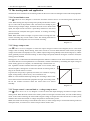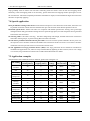
1
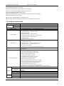
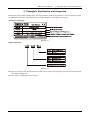
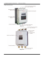
EMHEATER User’s Manual EM-GJ Series Soft Starter Europe North America Asia EMHEATER Africa Southeast Asia South America Oceania China EM Technology Limited Address : Phone: Fax: Zip code: Website : No.80, Baomin 2 road, Xixiang, Bao'an District,Shenzhen ,China 86-0755-29985851 86-0755-29970305 518101 www.emheater.com China EM Technology Limited EM-GJ User's Manual Safety Clauses Safety Clauses Thanks for your using EMHEATER intelligent motor soft starter, this product is used for three-phase squirrel cage induction motor soft starting and soft stopping control. Before using, please carefully read and understand the contents of this manual. In the process of using the soft starter, please note the following Safety Clauses: Please check this user manual carefully before using the product. Only the technical person is allowed to install the product. To be sure that the motor is correctly matched with the soft starter. It is forbid to connect capacitors to the output terminals (U V W). Please seal the terminal switch insulation glue after finishing connect them. The soft starter and its enclosures must be fixedly earthed. During the maintenance and repair, the input must be off-power. This user manual content may be changed due to technical reasons or modified. We reserve the updating right. I Table of Contents EM-GJ User's Manual Table of Contents 1. EM-GJ Series Soft Starter ..................................................................................................................................... 1 1.1 Motor soft starter profile ................................................................................................................................. 1 1.2 The main function............................................................................................................................................ 1 1.3 The main feature of soft starter........................................................................................................................ 1 1.4 Technical specification .................................................................................................................................... 2 2. Nameplate Explanation and Inspection ................................................................................................................. 3 3. Usage Condition and Installation........................................................................................................................... 5 3.1 The usage condition ......................................................................................................................................... 5 3.2 The installation requirement ............................................................................................................................ 5 3.3 The installation dimensions ............................................................................................................................. 6 3.4 Installation diagram ......................................................................................................................................... 7 4. Connection and External Terminal ........................................................................................................................ 8 4.1 The diagram connection .................................................................................................................................. 8 4.2 The external terminal ....................................................................................................................................... 8 4.3 The communication interfaces......................................................................................................................... 9 4.4 The diagram of main circuit connection ........................................................................................................ 10 5. Control Panel and Operation ................................................................................................................................11 5.1 The operation of control panel........................................................................................................................11 5.2 Parameters set and explanation...................................................................................................................... 12 5.3 Parameters code function explanation ........................................................................................................... 14 5.4 Helping message and explanation ................................................................................................................. 14 5.5 The complete solution of default setting and user debugging ....................................................................... 15 6. Protection Functions and Directions .................................................................................................................... 16 6.1 Protection classes and explanation ................................................................................................................ 16 7. Test Run and Application .................................................................................................................................... 18 7.1 Power on to test running ................................................................................................................................ 18 7.2 The starting mode and application................................................................................................................. 20 7.2.1 Current-limit to start ............................................................................................................................... 20 7.2.2 Voltage ramp to start............................................................................................................................... 20 7.2.3 Torque control + current limit or + voltage ramp to start....................................................................... 20 7.2.4 Current ramp to start .............................................................................................................................. 21 7.2.5 Voltage current-limiting double closed-loop start .................................................................................. 21 7.3 The stopping mode and application ............................................................................................................... 21 7.3.1 Soft-stopping Mode ................................................................................................................................ 21 7.3.2 Free-stopping Mode ............................................................................................................................... 21 7.4 Special application......................................................................................................................................... 22 7.5 Application examples .................................................................................................................................... 22 Appendix I ............................................................................................................................................................... 23 Appendix II .............................................................................................................................................................. 24 Quality Warranty ..................................................................................................................................................... 26 II EM-GJ User's Manual 1. EM-GJ Series Soft starter 1. EM-GJ Series Soft Starter 1.1 Motor soft starter profile Intelligent motor soft starter, the use of intelligent digital control; With the single chip processor as the intelligence center, thyristor module for actuators for full automatic control motor. It applies various squirrel-cage asynchronous motor control of load, the motor can smooth starting under any working conditions, protect the drag system, reduce the starting current impact on power grid, ensure reliable motor starting. Smoothly soft stopping function can effectively solve the inertial system surge problem, eliminate the drag system of inertial impact, that is traditional equipment cannot be achieved. Intelligent digital motor soft start equipment system with the complete protection function, extend the service life of the system, reduce the cost of system cost, improve the reliability of system and compatible with all the functions of starting equipment; It is a new ideal alternative for traditional star triangle starter and self-coupling decompression starter. 1.2 The main function Effectively reduce the starting current of the motor; Can reduce the distribution capacity, avoid grid expansion investment. Reduce the starting stress of motor and load equipment; Prolong the service life of the motor and related equipments. Soft stopping function can effectively solve the parking surge problem of inertial systems; That is a traditional starting equipment cannot be achieved. With six unique starting mode; To adapt to the complex motor and load, achieve perfect priming effect. With complete and reliable protection function; effectively protect the safety of motor and related production equipment. Intelligent motor soft starter, the application of network technology used motor control technology to adapt to the rapid development of electric power automation technology in the higher requirements. 1.3 The main feature of soft starter Reliable quality The computer simulation design. SMT production process. Good EMC performance. The machine before delivery on the high temperature aging, vibration test. Perfect and reliable system protection function Protection of no voltage, less voltage and over voltage. Protection of overheating and starting time too long. Protection of Input phase lost, output phase lost and 3phase unbalance. Protection of starting over current, running overload, and load short circuit protection. Maintenance function Fault self-diagnosis(short circuit, over voltage, less voltage, one phase grounded, motor overload, one phase lost, motor blocked, and intelligent software can inspect drag system working state). Combination of modular design, according to the fault display content, quick troubleshooting. Independent intellectual property products 1 1. EM-GJ Series Soft starter EM-GJ User's Manual Independently software copyright. Motor starting and protection proprietary technology. Unique way to detect debug equipment and process. Quick and thoughtful after-sales service Reliable performances lay the foundation of qualified service and quality. Provide perfect system solution. The timely and thoughtful Consulting Services. Constantly improve the product performance according to user's opinion. 1.4 Technical specification Item Input Power Input Voltage Supply Frequency Adaptive Motor Starting Times Description Three-phase 220V/380V/480V/660 AC 50/60Hz Squirrel-cage three-phase asynchronous motor It is recommended not to exceed 20 times per hour. (1) Operation panel control. (2) Operation panel + external control. (3) External control. (4) External control + COM control. Control Mode (5) Operation panel + external + COM control. (6) Operation panel + COM control. (7) COM control. (8) No start or stop operation. (1) Current-limiting to start. (2) Voltage ramp to start. (3) Torque control + current-limiting to start. Start Mode (4) Torque control + voltage ramp to start. (5) Current ramp to start. (6) Voltage current-limiting double closed-loop start. (1) Soft stop. Stop Mode (2) Free stop. (1) Open loop protection for external instantaneous stop terminals. (2) Over-heat protection for soft starter. (3) Protection for too long starting time. (4) Input open phase protection. (5) Output open phase protection. (6) Unbalanced three-phase protection. (7) starting over current protection. Protective Function (8) Running overload protection. (9) Under voltage protection for power voltage. (10) Overvoltage protection for power voltage. (11) Protection for fault parameter setting. (12) Load short circuit protection. (13) Auto restart or incorrect wiring protection. (14)Incorrect wiring protection of external control stop terminals. Place to be used Indoor location with good ventilation free from corrosive gas and conductive dust. Below 1000M. It have to rise the rate power when the altitude is more than Altitude 1000M. Ambient Temperature -30 +55 oC Humidity 90%RH without dew condensation. Vibration <0.5G Protection Class IP20 Structure Cooling Pattern Natural wind cooling. 2 EM-GJ User's Manual 2. Nameplate Explanation and Inspection 2. Nameplate Explanation and Inspection Please check up the products before using, if in some problems; please do not hesitate to contact us with any request for additional information. Check-up the type of product whether it is the right one you order. Nameplate explanation: Diagram 2.1 Model explanation: Diagram 2.2 Check any damage to the product because of the transport, such as the spare parts are apart from the main body or the shell be damage etc. Check others, including the user's manual. 3 2. Nameplate Explanation and Inspection EM-GJ User's Manual Outline of the soft starter: Diagram 2.3 Diagram 2.4 4 EM-GJ User's Manual 3. Usage Condition and Installation 3. Usage Condition and Installation It is strict rule for the users to use or install the soft starter according to the requirement; otherwise, it will be in bad result. 3.1 The usage condition Power Supply: City grid power, self-provided power, diesel oil dynamotor, 3-phase alternating current 220V/380V/480V/660V±15%, 50Hz or 60Hz. The power capacity of the soft start must meet the motor starting requirement. Matched Motor: Motor should be three phase squirrel asynchronous motor, and its power capacity must be matched with soft starters. Starting Frequency: The starting time is according to the loading equipments. Cooling Mode: Naturally wind cooling. Protective Grade: IP20 Environment Conditions: when altitude is less than 1000m, the temperature of the environment should be between -25oC ~ 40 oC, relative humidity should be less than 90% RH, no vapor, no flammable, volatile, corrosive gas. No electric dirt, indoor installation, ventilated, vibration is less 0.5G. 3.2 The installation requirement The direction and distance of installation: In order to make sure that the soft starter be in good ventilation and heat dissipation, please install the product in vertical direction, and be sure the space around the product is enough. (See the following diagram 3.1) If the soft starter is installed in a box, please note that the ventilation is very good, as well as the above notes. (See the following diagram 3.1) Diagram 3.1 Diagram 3.2 Diagram 3.3 5 3. Usage Condition and Installation EM-GJ User's Manual 3.3 The installation dimensions The external shape and installation dimensions of 5.5KW ~ 75KW(Diagram 3.4). Dimensional drawing Mounting holes schematic Model 220V 380V Power Current 480V External Installation N.W Dimensions (mm) Dimensions (mm) (KW) (A) H1 W1 D H2 W2 d (K.G) --- EM-GJ3-5d5 EM-GJ4-5d5 5.5 11 270 146 160 248 132 M7 <5 --- EM-GJ3-7d5 EM-GJ4-7d5 7.5 15 270 146 160 248 132 M7 <5 EM-GJ4-011 5.5/11 23 270 146 160 248 132 M7 <5 EM-GJ2-7d5 EM-GJ3-015 EM-GJ4-015 7.5/15 30 270 146 160 248 132 M7 <5 EM-GJ3-018 EM-GJ4-018 18.5 37 270 146 160 248 132 M7 <5 EM-GJ2-011 EM-GJ3-022 EM-GJ4-022 11/22 43 270 146 160 248 132 M7 <5 EM-GJ2-015 EM-GJ3-030 EM-GJ4-030 15/30 60 270 146 160 248 132 M7 <5 EM-GJ2-018 EM-GJ3-037 EM-GJ4-037 18.5/37 75 270 146 160 248 132 M7 <5 EM-GJ2-022 EM-GJ3-045 EM-GJ4-045 22/45 90 270 146 160 248 132 M7 <5 EM-GJ2-030 EM-GJ3-055 EM-GJ4-055 30/55 110 270 146 160 248 132 M7 <5 EM-GJ2-037 EM-GJ3-075 EM-GJ4-075 37/75 150 270 146 160 248 132 M7 <5 EM-GJ2-5d5 EM-GJ3-011 --- : The rated power of motor in the above form is the maximum rated value. Generally, the values of matched motor power capacity should not be more than this value. 6 EM-GJ User's Manual 3. Usage Condition and Installation The external shape and installation dimensions of 90KW ~ 600KW(Diagram 3.5). Dimensional drawing Model 220V Mounting holes schematic Power Current (KW) (A) W1 257 D 198 H2 382 W2 192 d (K.G) 180 H1 515 EM-GJ2-045 EM-GJ3-090 EM-GJ4-090 45/90 M9 <21 EM-GJ2-055 EM-GJ3-115 55/115 230 515 257 198 382 192 M9 <21 132 264 515 257 198 382 192 M9 <21 EM-GJ2-075 EM-GJ3-160 EM-GJ4-160 75/160 320 515 257 198 382 192 M9 <21 EM-GJ2-090 EM-GJ3-185 EM-GJ4-185 90/185 370 515 257 198 382 192 M9 <21 EM-GJ2-100 EM-GJ3-200 EM-GJ4-200 100/200 400 515 257 198 382 192 M9 <21 EM-GJ2-132 EM-GJ3-250 EM-GJ4-250 132/250 500 515 257 198 382 192 M9 <21 EM-GJ2-160 EM-GJ3-280 EM-GJ4-280 160/280 560 515 257 198 382 192 M9 <21 EM-GJ2-185 EM-GJ3-320 EM-GJ4-320 185/320 640 560 285 248 460 260 M9 <25 320 640 560 285 248 460 260 M9 <25 200/400 220/450 250/500 315/600 800 900 1000 1200 590 590 665 665 331 331 410 410 248 248 248 248 497 497 547 547 265 265 345 345 M9 M9 M9 M9 <30 <30 <42 <42 --- --EM-GJ2-200 EM-GJ2-220 EM-GJ2-250 EM-GJ2-315 380V 480V External Installation N.W Dimensions (mm) Dimensions (mm) EM-GJ4-115 EM-GJ3-132 EM-GJ4-132 EM-GJ3-355 EM-GJ4-355 EM-GJ3-400 EM-GJ3-450 EM-GJ3-500 EM-GJ3-600 EM-GJ4-400 EM-GJ4-450 EM-GJ4-500 EM-GJ4-600 3.4 Installation diagram The EM-GJ series soft starter has three types of connection as following: Main circuit connection: It contains the wiring of 3-phase source input, the output to motor, and the pass -by contactor connection. External terminal connection: That is the wire comes from twelve external terminals which including control signal and analogue output signal. Communication connection: One standard RJ-45 network cable socket and one DB9 socket can be used to connect computer or network. 7 4. Connection and External Terminal EM-GJ User's Manual 4. Connection and External Terminal 4.1 The diagram connection Diagram 4.1 4.2 The external terminal Please see the diagram diagram 4.2: 8 Diagram 4.2 Terminal ① ② are by-pass output, are used to control the by-pass contactor. They are normal open contacts and are closed when finishing starting. The terminal contact capacity is AC 250V/5A. Terminal ③ ④ are programmable relay output: The delay time is set by code. The output command type is set by code. They are normal open no-power terminals, being close when output valid. Please see the detailed information in item 5.3. This terminal contact capacity is AC250V/5A. Terminal ⑤ ⑥ are fault output , they will be closed when there are any fault matters happened to the soft starter or electricity lost, while at normal case they are open. This terminal contact Capacity is AC250V/0.5A. Terminal ⑦ are instantaneous stop input, this terminal must be connected with terminal ⑩ when the starter works normally. But if these two terminals are open, the soft starter will stop, and at this time the starter is at the EM-GJ User's Manual 4. Connection and External Terminal state of fault protection. This terminal ⑦ can be controlled by the normally closed output terminals of external protection device, and it is useless when the code is set to 0(Primary protection). Terminal ⑧ ⑨ ⑩ are startup or stop input .There are two ways of connections for your selection; those are 3-wire connection and 2-wire connection. Please see the diagram 4.3 Diagram 4.3 Terminal ⑪ ⑫ are DC 4 ~ 20mA analogue output ,they indicate the current value of motor at real-time working. The 20mA is full-scale value and that is four times than rated current of nominal power of soft starter, while, we can connect a 4 ~ 20mA DC current meter to check. The max value of output load resistance is 300Ω. Note: Please make sure that external terminals are in right connection; otherwise, the product may be damaged. 4.3 The communication interfaces RJ-45 is the standard web line socket. DB9 socket has RS485 and RS232 interfaces inside. Please see the diagram 4.4 Diagram 4.4 ① is RS485+ ⑥ is RS485② is RS232 output. ③ is RS232 input. ④ is +5V output (limit-current is 50mA) ⑤ is earthed GND. ⑦⑧⑨ are empty. The user can choose the following software: Computer collector distribution control communication software. Device Net interface card and communication. Device Net/Mod-bus/Profi-bus gateways. Others. 9 4. Connection and External Terminal EM-GJ User's Manual 4.4 The diagram of main circuit connection Please see the diagram 4.4. Diagram 4.4 10 EM-GJ User's Manual 5. Control Panel and Operation 5. Control Panel and Operation The motor soft starter has five kinds of working state; Ready ,Run ,Error, Starting and Stopping, the showing parameter is easy to understand and modify. 5.1 The operation of control panel Diagram 5.1 Open state: Please do not press the "RUN" key until the ready-lamp lights and show . Time-delay state: When the ready-lamp or fault-lamp is shining, it means it is interval time delay; and when the display screen shows "dEXXX" and count down, that means staring time-delay. The "RUN" or "STOP" key: In the process of staring, the panel shows "XXXX" that is the value of start-up current .At this time only "STOP" key is valid. And the lamps of ready, Run and Error are all dark, and you can't come into the "Set Menu" and "Help Menu" state. While, in the process of stopping, the panel shows "XXXX" that is the value of motor current. At this time, only "RUN" key is valid, and the lamps of Ready, Run and Error are all dark, and you can't come into the "Set Menu" and "Help Menu" state. The "STOP" key also has reset function. The "SET" key: Press "SET" key to enter the "Set Menu" and panel shows FX:XXX. Please press "SET" key again and Colon is shining, then you can change the parameters after the colon you need. If you want to save the parameter change, please press "YES" key. If you do not want to save, please press the "SET" key until the colon stops shining, then the parameters recover. Having finished the above operation, please press the "YES" key to exit or press "STOP" key to exit directly. The "YES" key: Under non-Set State, press the "YES" key to enter "Help Menu" and the panel shows HX: XXX. When you finish reading the "Help Menu", you can press "YES" key again or "STOP" key to exit. Under Set State, This key can save parameters, and press again can exit set state. The "UP" and "DOWN" key: In "Set Menu", when the colon is not shining, you can press these two keys to select the Function Code; When colon is shining, you can press these two keys to change parameters. It is the same as the operation in "Help Menu". When the Pass-by -lamp is lighting and the display Screen shows AXXX which means the operation current value of motor, now you can press "UP" or "DOWN" key and the screen will display PXXXX or HXXXX. (PXXXX means the apparent power of motor; HXXXX means the over-load heat balance coefficient, if this value is more than 100%,the screen shows , that means soft starter is at state of over-load protection. ) 11 5. Control Panel and Operation EM-GJ User's Manual 5.2 Parameters set and explanation The explanation for "Parameter-set" codes. 30% Default 30~70% Setting range This code can be used when the starting mode is set as "Voltage ramp to start", and if the motor load is heavy, please set F0=40%, or higher a little. Under "Limit-current" mode ,the F0 value will be fixed as 40%. 16S Default Soft starting time 2~60S Setting range It is used to set longest soft starting process time, and soft starting time maybe shorter for different load. It is invalid under "Limit-Current" starting mode. 0S Default Soft stopping time 0~60S Setting range If the code set as "0", the motor will free stop. One soft starter for 2 motor, this code should set "0". 0S Default Start-up time delay 0~999S Setting range Delay is with countdown mode; If set as "0", the starter will start up the motor immediately. 0S Default Programming time-delay 0~999S Setting range This code is used to set delay time of ③&④ terminals output. Set "0" immediately close. (Please refer to FE for details) 400% Default Start-up current limited value 50~500% Setting range It is used when the staring mode is "current limit", and the value will be fixed as 400% when the starting mode is "Voltage ramp to start" 100% Default Maximum current of soft starter 50~200% Setting range The "50 ~ 200%" is basic on the nominal current of motor. If the set value of this code over 200%,the soft starter will reverse to overheat protection. 80% Default Lower voltage protection 40~90% Setting range When the working voltage is under the voltage range(80%),the soft starter will be low voltage protection 120% Default Over voltage protection 100~130% Setting range When the working voltage is over the voltage range(120%),the soft starter will be over voltage protection 1 Default Modes of starting 0~6 Setting range 0: Limit-current to start 1: Voltage ramp start 2: Torque control + limit current 3: Torque control + voltage ramp 4: Current ramp start 5: Double closed loop 6: Monitoring 4 Default Protection Level 0~4 Setting range 0. Primary protection 1. Light-load protection 2. Standard protection 3. Heavy-load protection 4. The superior level protection Initial voltage * * 12 EM-GJ User's Manual Operation control mode 5. Control Panel and Operation Default Setting range 1 0 ~6 Default Setting range 1 0~2 Default Setting range 0 0~63 Default Setting range 6 0~19 Default Setting range 80% 20~100% 0: Run by keypad 1: Run by keypad and terminal 2: Run by terminal 3: Run by terminal and RS485 4: Run by keypad, terminal and RS485 5: Run by keypad and RS485 6: Run by RS485 Parameter revise 0: Parameter revise prohibit; 1: Partial parameter revise prohibit; 2: All parameter allow revising. * Communication address Many soft starters connect with upper computer. * Programming output Setting the detailed in Item 5.3 * Soft-stopping limited current Setting the detailed in Item 7.3 Rated value Default --Setting range "The rated current of motor" is the same as the motor nominal current. If your motor rated power is much lower than soft starter, please revise the FP same as motor rated current. And then soft starter can protect small KW motor. If you meet Error 05, please change FA=2. 5s Default By pass suck time 0~99s Setting range This parameter can delay soft starter switching to bypass contactor time. If soft starter starts very heavy fan or pump, please set the parameter to 10 or 15 seconds. 1 Default 3 phase balance valid 0~1 Setting range 0: Invalid 1: Valid 100% Default Current coefficient 50~150% Setting range Showing current slants high, to set coefficient down; Lower conversely 100% Default Voltage coefficient 50~150% Setting range Showing voltage slants high, to set coefficient down; lower conversely Motor rated current * * * * Note: the "Max working current", is basic on the value of FP (nominal current of motor). If you have no any operation for 2 minutes after you come into the "set" state, soft starter will exit from "set" state. You can not set any parameters in the process of starting or stopping. If you press the "YES" key to power on soft starter, all parameters will recover to default setting except code. When =1, these parameters with "*" is prohibited to revise. When =2, all parameters can be revised. 13 5. Control Panel and Operation EM-GJ User's Manual 5.3 Parameters code function explanation The parameter is used to set the control ways of soft starter; as the following form: Numerical value 0 1 2 3 4 5 6 Keypad 1 1 0 0 1 1 0 External terminal control 0 1 1 1 1 0 0 RS485 Communication 0 0 0 1 1 1 1 Note: In the above form,"1" is allowing,"0" is forbidding. For example, If you press keypad "RUN", and meet , please set =0. And then soft starter can be run by keypad. If the "External Control" is allowing, you must contact a normally closed switch button between the terminal ⑦⑧ and terminal ⑩, otherwise the soft starter can’t start-up the motor and show " / ". The parameter is use to setting the way of ③&④ programmable relay output, As the following form: The number setting by FE The moment of programmable relay output 0(10) When sending the order of starting , the program output 1(11) When beginning to start , the program output 2(12) When at the start of bypass operation, the program output 3(13) When sending the order of stopping, the program output 4(14) When finishing the operation of stopping, the program output If users need programmable relay output time delay, the time can be setting by parameter . When the is setting as 5~9(15~19), the terminal ③&④ will display the state of programmable relay output. As the following form: The number setting by FE The state of programmable relay output 5(15) Error state 6(16) Working state 7(17) Ready state 8(18) Starting state 9(19) By-pass operation state The state of programmable relay output is used to show the working state of soft starter, and under this way, the setting delay time is invalid; The default setting of code is "7" showing the ready state of soft starter and at this state the motor can be started up; When the code is "5" outputting error state of motor, Terminal ③ ④ can output fault such as: ( , , , , , and ). This will not affect the function of ⑤⑥ error output terminals. When >9, the programmable output will be “reverse phase output”, (Normal open will reverse to normal close). When =0, all parameters cannot be revised. And when =1, ( , , , , , ) cannot be revised. When =2, all parameters can be revised. 5.4 Helping message and explanation When the product is not starting or stopping ,or not at the ”set” state, you can press "YES" key and come into helping menu ,then press the "UP" or "DOWN" key to choose the help message. Please press "YES" or "STOP" key to return. Helping message Form 14 EM-GJ User's Manual Message displayed 5. Control Panel and Operation Explanation That is the 3-phase power voltage is AC 380V. That is the specification is AC 380V, 50Hz, 30A. The fault message Err01 that happened at the last time. : : It says no fault happened. It says the software of the products is Ver3.0. is times of successful soft starting is last soft starting time Note: The message H1 ~ H9 displayed means 9 faults records that happened lately. Not in state of soft starting and stopping, and not in setting state, to press "YES" key to enter helping menu, and press "UP" or "DOWN" key to choose helping information. Under state of helping, to press "YES" key or" STOP" key to quit helping menu. 5.5 The complete solution of default setting and user debugging The system integrator or final user do not have proper motor for testing, but you can use star wiring by 3 piece 100W or 200W electric lamps or small KW motor for testing. At this moment, because the output current is very small, so the soft starter will alarm "output phase lost" and stop, so user needs to change parameter to 0 (Primary protection) , and soft starter will not alarm, and after starting, the 3 lamps will be light and gradually brighter, lastly bypass contacted and lamps be full bright. Diagram 5.2 15 6. Protection Functions and Directions EM-GJ User's Manual 6. Protection Functions and Directions We make our soft starters have all kinds of protection functions to protect the safety of soft starter and the motor. Please choose the correct protection Class and parameters according to your application conditions! Over-heat protection: When soft starter inside temperature is up to 80oC ± 5oC, the starter will turn to over-heat protection, when be down to 55 oC, this protection removes. Input less-phase protection: The delayed time < 3s Output less-phase protection: The delayed time < 3s Three-phase unbalance protection: The delayed time < 3s, when the difference of current among three phrases is more than 50% ± 10%, the protection be valid. Starting over-current protection time: The diagram of over current 5 times of set rated working current is just as diagram 6.1. Working over-load protection time: The starter will be in inverse time thermal protection on. Base of the Max working current of motor (Set by ), (The diagram 6.1 show) Low voltage protection delay time: When power voltage is less than 40%, the protection delayed time < 0.5s; When power voltage is less than 80%, the protection delayed time < 3S. Over-voltage protection delay time: When power voltage is more than 140%, the protection delayed time < 0.5S; When power voltage is more than 120%, the protection delayed time < 3S. Loads short-circuit protection delay time: The protection delayed time < 0.1S. 6.1 Protection classes and explanation According different usage conditions, EM-GJ series Soft Starter has five protection classes, as following: 0. Primary protection 1. Light-load protection 2. Standard protection 3. Heavy-load protection 4. The superior protection Primary protection includes the protection functions of overheat, short circuit, and input default phase protection and prohibit external instantaneous stop terminal. Which is proper urgently startup conditions, such as fire pump. The protections of light load, standard and heavy-load have the overall protection function of soft starter. The difference among them is protection level of overload and over current. See the diagram of 6.1. Under the superior protection, the soft starter has a higher protection level. The protection classes and the time of heat protection as (diagram 6.1) FA code The grade of overload protection The grade of over-current protection 16 0:Basic protection 1:Light-load protection 2:Standard protection 3:Heavy-load protection 4:Superior protection Note No 2 grade 10 grade 20 grade 10 grade Standard of IEC60947-4-2 No 3 Second 15 Second 30 Second 15 Second The 5 times of current EM-GJ User's Manual 6. Protection Functions and Directions 0:Basic 1:Light-load 2:Standard 3:Heavy-load 4:Superior Note protection protection protection protection protection The multiple to the rated 3 4 5 3 4 5 3 4 5 3 4 5 They are the Overload current typical values drop-away time Drop-away 4.5 2.2 1.5 23 12 7.5 46 23 15 23 12 7.5 time (S) FA code Diagram 6.1 (IEC60947-4-2 standard) Motor heat protection curve (overload drop-away time) Remark: set value should be same as motor nameplate rated current. The set value should not be less than 20% of soft starter rated current, otherwise the overheat protection will be useless because of big tolerance. 17 7. Test Run and Application EM-GJ User's Manual 7. Test Run and Application Please do some examinations before test running as following: Whether the rated power of soft starter is matched with the Motor. Whether the insulation of motor meets requirement. Whether the main circuit connection of input and output is correct. Whether all the screws of terminals are twisted tightly. 7.1 Power on to test running After Power on, please do not disassemble the soft starter cover that is dangerous! Power on, soft starter displays , and the Ready is light, then you can press "RUN" key to start. Set be same as motor nameplate rated current. After started the motor, you should examine whether the motor running direction is correct, or whether runs normally. If not, you can press "STOP" key or cut off the power to stop running. If the soft starter starting state is not satisfied. Please see the detailed explanation at 7.2: the starting mode and application If the start torque is not enough, you can change the starting voltage (when the starting mode is voltage control) or the certain current value (when the mode is current control) to improve start torque. Do not open the face cover in case of electric shock. If there is any abnormal voice, smoke or taste, please cut off power as soon as fast, and check the reason. When the starter power on or be in starting, the error lamp is lighting and screen displays "Err??", at this time, you can check diagram 7.1 to find out reason . Press "STOP" key or external stop button can reset the error state. Note: When ambient temperature is less than -10oC, the starter should be power on to preheat for 30 minute, and then to start. Error Code Fault Type The fault is removed Reason and Any faults are removed, such as low-voltage, over-voltage, over-heat. Now the Ready-lamp is lighting and you can start the motor. solution Error Code Fault Type The external instantaneous stop terminal is open Reason and Please connect the external instantaneous stop terminal (terminal ⑦) and stop terminal 8 with the public terminal (terminal ⑩) together. solution Error Code Fault Type The soft starter is over heat Reason and The soft starter is started too frequently, or the soft starter rated current is smaller than motor, or motor is heavy over load. solution Error Code Fault Type The starting time is over long, which is longer than 60s. The starter parameter is set wrong; or the motor load is heavy, or voltage transformer capacity is Reason and not enough; or power supply cable is too long. If soft starter capacity is enough and load is heavy solution fan or pump, please set FU to 10 or 15 second. Error Code Fault Type Input phase failure Reason and Please check whether the input circuit connections, bypass contactor and the controlled silicon is open or whether the thyristor wire is not connected. solution Error Code 18 Fault Type Output phase-failure EM-GJ User's Manual 7. Test Run and Application Please check whether the output circuit connection, bypass contactor and the controlled silicon Reason and are short circuit, or whether the thyristor wire is connected well; The power supply should connect to R,S,T, and bypass contactor should connect with L1,L2,L3; If motor KW is much solution smaller than soft starter, please set parameter FA=2. Error Code Fault Type Three-phase unbalance Reason and Please check the input three-phase power voltage is balance or not, and check the motor 3phase is abnormal. Or set parameter FC=2 and E1=0. solution Error Code Fault Type Starting over current Reason and Overload, or the motor is not matched with the soft starter. solution Error Code Reason and Overload or the solution Error Code Fault Type Running over load code is set wrong. Fault Type Low voltage Reason and Please check the voltage of input power or the solution Error Code Fault Type Over voltage Reason and Please check the voltage of input power or the solution Error Code item is set wrong. item is set wrong. Fault Type The parameters are set wrong Reason and Please change the parameter correctly, or you can press the "YES" key to power on the starter again to recovery the default setting. solution Error Code Fault Type Load short circuit Reason and Check load and the controlled silicon is short circuit or overload. solution Error Code Fault Type The wiring of automatic Re-start is wrong Reason and The external terminals is not connected according the 2-wire way. solution Error Code Fault Type The wiring of external terminal is wrong =0,When external control mode is allowing, the external stop terminal is open, and Reason and Change soft starter cannot start. solution Error Code Fault Type Motor less load Reason and Please match the appropriate motor. solution Error Code Fault Type ⑧,⑩ terminal open circuit Reason and Please check and connect⑧,⑩. solution Note: When the motor starts successfully, ① and ② will close to suck by pass contactor running. At this time, if the contactor is not closed, the motor will stop running, so you can check whether the wiring of the bypass contactor is right. 19 7. Test Run and Application EM-GJ User's Manual 7.2 The starting mode and application The EM-GJ series soft starter has six starting modes for the user to select according the motor and load equipments. 7.2.1 Current-limit to start (The code is set as"0") Diagram 7.1 shows the waveform of motor current . I1 is the starting limit-current preset value. When starting, the output voltage rises quickly till the motor current up to I1 value and not beyond this value. The motor runs steadily in pace with the rising of output voltage, and when the motor runs to be the rated speed, the output current will have a quick-drop and down to the motor rated current (Ie value),then the bypass contactor is working, the stating process finished. Note: When motor load is too light or I1 preset value is too high, the max current of starting may can not reach I1 value. This starting mode fits for the conditions which requires strict current limit of starting. Diagram 7.1 7.2.2 Voltage ramp to start (The code is set as"1") Diagram 7.2 shows the output voltage waveform. In the diagram, the U1 is the initial voltage value of starting. When starting, if the motor current is not more 400% than the rated current, the output voltage of soft starter will rapidly rise to U1, and the output voltage rises gradually to the rated voltage (Ue), and the motor gradually increase and until running at rated voltage and speed, and then the bypass contactor closed, the starting process finished. Starting time "T" is obtained in the standard experiment under the condition of soft starter with standard load. And soft starter takes this control parameters as a benchmark, smooth acceleration by controlling the output voltage to motor starting process to complete, not mechanically controlled time "T" and regardless smooth of whether the motor speed. In view of this, when the load is lighter, starting time are often less than the set starting time, as long as can smooth starter is normal In general, the voltage ramp is generally used mode; it is suitable for requiring higher starting stability without strictly current limitation case. Note:"T" is the automatic detecting starting time according to load. It will be less than set time when the load equipments are light; this starting mode fits for the common occasions where the motor need to be started smoothly. Diagram 7.2 7.2.3 Torque control + current limit or + voltage ramp to start (The code is set as "2" or "3") Diagram 7.3 and 7.4 shows the output changing waveform of torque control starting mode. When the static friction force of heavy load is too stronger to start the motor, user can use this starting mode. At first state of starting, the motor needs a higher voltage to conquer the static friction force of heavy load, and then starts with current-limit or voltage ramp mode to start the heavy motor. Note: This mode will cause big-current shock to the motor, so if the voltage ramp or current limit starting mode can startup the motor, it is better not to use this torque control mode to start. 20 EM-GJ User's Manual Diagram 7.3 7. Test Run and Application Diagram 7.4 7.2.4 Current ramp to start (The code is set as"4") Diagram 7.5 shows the output current waveform. The I1 in the diagram is current value preset by code, and T1 is time value present by code. This starting mode has very stronger speed-up ability and is suit for the bipolar motors, and it can reduce the starting time. Diagram 7.5 7.2.5 Voltage current-limiting double closed-loop start (Both voltage ramp and current limit) to start (The items set as"5"). This starting mode uses voltage ramp and current limit double closed loop circuit; it is a composite starting mode. The output voltage waveform is changed as different motor and the load equipments. This mode fits for smooth starting and strictly current limit occasions. 7.3 The stopping mode and application The soft starter has two stopping modes; those are Soft-stopping mode and Free-stopping mode. 7.3.1 Soft-stopping Mode (The item is not set as"0") When using this mode to stop the motor, the power supply of motor will be transferred from the bypass contactor to the controlled silicon of soft starter, and the output voltage of starter will be reduced gradually so that the running speed of motor can be cut down smoothly avoid mechanical shock. The output ending voltage is the same as the starting initial voltage. Soft-stopping mode can reduce or remove the surge of the loading equipments such as the water pump. You can set the soft-stopping current limit value through the code to reduce the high current shock to the motor when stopping. This current limit value is percentage of . 7.3.2 Free-stopping Mode (The code is set as"0") When using this mode to stop the motor, the soft starter will cut off the connection to the bypass contactor and forbid the controlled silicon output voltage after receiving stopping command. The motor 21 7. Test Run and Application EM-GJ User's Manual stops gradually with its inertia. One soft start connecting with two motors must use this free stopping mode. Generally, if the soft stopping mode is not necessary, please choose the free stopping mode to prolong the service life of soft starter. This mode completely forbids the instantaneous output; avoid instantaneous high current shock to the motor of specially applying. 7.4 Special application In parallel the starting of the motors: If the motors total power is less than 80% of soft starter, the motors can be parallel connection. But at this time should be also provides for each motor thermal protection device. Double speed motor: Motor soft starter can cooperate with double speed motor starting, must go through demagnetization delay period before change from low speed to high speed, to avoid anti-phase current generated between the lines and motor. Too long cable: f the cable is too long, the cable voltage drop will be high, and that will increase current loss and reduce starting torque, so please use big KW soft starter and motor. Soft starter parallel connected with one power-line: If several soft starter parallel installed in the one power line, the input line reactor should be installed in the middle of the transformer and the soft starter circuit. Reactor should be installed at each line input side between circuit breaker and soft starter. The application of surge protection device (SPD): The surge protection device should be considered to installed in the application case, where is easily caused trouble by lightning or other reasons, such as over voltage, over-current, surge interference. Please refer to SPD related documents for details. 7.5 Application examples The parameters of the different loads are different, please refer to diagram 7.2. The loading Voltage ramp stopping time(s) Initial voltage Voltage ramp (current limit) Current limit to start Ball mill machine Fan Centrifugal Piston compressor 20 6 60% 400% 350% 26 16 4 20 30% 40% 400% 400% 350% 250% 16 4 40% 400% 300% hoister 16 10 60% 400% 350% 16 2 50% 400% 300% 16 10 50% 400% 350% 16 2 40% 400% 300% 20 10 40% 400% 200% 16 20 16 2 10 20 30% 40% 40% 400% 400% 400% 300% 250% 300% Stirring machine Breaker Screw compressor Rotating conveyor Light load Convey belt Heat pump 22 Voltage ramp starting time(s) EM-GJ User's Manual Appendix II Appendix I The soft start (5.5KW~600KW) selection list of peripheral appliances are as follows: Model Rated power (KW) Rated current (A) Breaker (A) By-pass contactor(A) Cable size (mm2) EM-GJ3-5d5 5.5 11 16 16 4 mm2 EM-GJ3-7d5 7.5 15 20 16 4 mm2 EM-GJ3-011 11 23 32 25 6 mm2 EM-GJ3-015 15 30 40 40 10 mm2 EM-GJ3-018 18 37 50 40 10 mm2 EM-GJ3-022 22 43 63 63 16 mm2 EM-GJ3-030 30 60 80 63 25 mm2 EM-GJ3-037 37 75 100 100 35 mm2 EM-GJ3-045 45 90 125 100 35 mm2 EM-GJ3-055 55 110 160 160 35 mm2 EM-GJ3-075 75 150 180 160 30×3 mm2 EM-GJ3-090 90 180 225 250 30×3 mm2 EM-GJ3-115 115 230 315 250 30×3 mm2 EM-GJ3-132 132 264 315 400 30×4 mm2 EM-GJ3-160 160 320 350 400 30×4 mm2 EM-GJ3-185 185 370 400 400 30×4 mm2 EM-GJ3-200 200 400 400 400 50×5 mm2 EM-GJ3-250 250 500 630 630 50×5 mm2 EM-GJ3-280 280 560 630 630 50×5 mm2 EM-GJ3-320 320 640 630 630 50×5 mm2 EM-GJ3-355 355 710 1000 1000 60×6 mm2 EM-GJ3-400 400 800 1000 1000 60×6 mm2 EM-GJ3-450 450 900 1000 1000 60×6 mm2 EM-GJ3-500 500 1000 1250 1000 80×6 mm2 EM-GJ3-600 600 1200 1600 1600 80×6 mm2 Note: The rated power and rated current indicate the maximum rated value of the soft start. The matching specification of breakers and bypass contactors should match with the motor. Soft starter is for six terminal inputs and three terminal outputs, it is still with the online protection function at the state of bypass contactor sucking, do not need to add additional motor protection device. 23 Appendix II EM-GJ User's Manual Appendix II 24 EM-GJ User's Manual Appendix II 25 Quality Warranty EM-GJ User's Manual Quality Warranty The warranty of soft starter is as follows: (1) Warranty period under normal conditions. We provide guarantees for repair and replacement in 1 month from the date of use. We provide guarantee for repair in 12 months from the date of use or 18 month from the date of ex-factory. (2) The purchaser enjoys life-long paid service whenever and wherever he uses a motor soft starter made in our company. (3) Service in the following cases, even within the warranty period, shall be charged to the purchaser: Problems caused by mal-operation in violation of this manual, or caused by unauthorized repair or renovation. Problems caused by improper use of soft starter that is off standard and requirement; Malfunction or damage caused by improper transit or storage after purchase; Induced failure or aging of the device due to poor ambient; Malfunction or damage caused by fire, flood, thunder, earthquake, abnormal voltage or other natural disasters; Unidentifiable nameplate, mark and ORD number due to intentional spoilage; Delayed or unsatisfied payment in violation of purchase appointment; Fail to give an objective description on the use of installation, wiring, operation, maintenance or else; (4) Defective products should be sent to us for repair, replacement and return, which can be proceeded only after verifying the burden of liability. (5) In case there is any quality problem or accident, we merely promise to bear the above-mentioned responsibilities. If a user needs more guarantees for liabilities, please assure on the insurance company voluntarily. Product Warranty Card Company address: Customer Information Company Name: Contact Person: Post Code: Tel: Product model: Product information Body barcode (Attach here): Name of agent: (Maintenance time and content): Failure information Maintenance personnel: 26