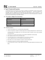
1
Report No. : FD251532 FCC TEST REPORT FCC TEST REPORT Authorized under Declaration of Conformity according to 47 CFR FCC Rules and Regulations Part 15 Subpart B, Class B Digital Device Equipment : Network Attached Storage Model No. : N7510, NDL-2755T Filing Type : Declaration of Conformity Applicant : Thecus Technology Corp 15F., No. 79, Sec. 1, Sintai 5th Rd., Sijhih Dist, New Taipei City 221, Taiwan Statement The test result refers exclusively to the test presented test model / sample. Without written approval of SPORTON International Inc., the test report shall not be reproduced except in full. Certificate or Test Report must not be used by the applicant to claim the product in this test report endorsement by TAF or any agency of U.S. government. SPORTON International Inc. 6F, No. 106, Sec. 1, Hsin Tai Wu Rd., Hsi Chih, Taipei Hsien, Taiwan, R.O.C. SPORTON International Inc. TEL : 886-2-2696-2468 FAX : 886-2-2696-2255 Report No. : FD251532 FCC TEST REPORT Table of Contents History of this test report....................................................................................................................................ii CERTIFICATE OF COMPLIANCE........................................................................................................................1 1. General Description of Equipment under Test.............................................................................................2 1.1. Applicant..........................................................................................................................................................................................2 1.2. Manufacturer ...................................................................................................................................................................................2 1.3. Basic Description of Equipment under Test ....................................................................................................................................2 1.4. Feature of Equipment under Test ...................................................................................................................................................2 1.5. Modification of EUT .........................................................................................................................................................................2 2. Test Configuration of Equipment under Test ...............................................................................................3 2.1. Test Manner ....................................................................................................................................................................................3 2.2. Description of Test System .............................................................................................................................................................4 2.3. Connection Diagram of Test System ..............................................................................................................................................6 3. Test Software ...................................................................................................................................................7 4. General Information of Test............................................................................................................................8 4.1. Test Facility .....................................................................................................................................................................................8 4.2. Uncertainty of Test Site ...................................................................................................................................................................8 4.3. Test Voltage ....................................................................................................................................................................................8 4.4. Measurement Procedure.................................................................................................................................................................8 4.5. Test in Compliance with ..................................................................................................................................................................8 4.6. Frequency Range Investigated .......................................................................................................................................................8 4.7. Test Distance ..................................................................................................................................................................................9 5. Test of Conducted Powerline .......................................................................................................................10 5.1. Description of Major Test Instruments ..........................................................................................................................................10 5.2. Test Procedures ............................................................................................................................................................................10 5.3. Typical Test Setup Layout of Conducted Powerline .....................................................................................................................11 5.4. Test Result of AC Powerline Conducted Emission .......................................................................................................................12 6. Test of Radiated Emission............................................................................................................................14 6.1. Description of Major Test Instruments ..........................................................................................................................................14 6.2. Test Procedures ............................................................................................................................................................................16 6.3. Typical Test Setup Layout of Radiated Emission..........................................................................................................................17 6.4. Test Result of Radiated Emission for Below 1GHz .......................................................................................................................18 6.5. Test Result of Radiated Emission for Above 1GHz ......................................................................................................................22 7. Photographs of Test Configuration .............................................................................................................24 7.1. Photographs of AC Powerline Conducted Emissions Test Configuration.....................................................................................24 7.2. Photographs of Radiated Emissions Test Configuration...............................................................................................................26 8. List of Measuring Equipment Used .............................................................................................................28 Appendix A. Photographs of EUT........................................................................................................ A1 ~ A27 SPORTON International Inc. TEL : 886-2-2696-2468 FAX : 886-2-2696-2255 Page Number : i Issued Date : Dec. 11, 2013 Report No. : FD251532 FCC TEST REPORT History of this test report Report No. FD251532 SPORTON International Inc. TEL : 886-2-2696-2468 FAX : 886-2-2696-2255 Version Issue Date Rev.01 Dec. 11, 2013 Description Initial issue of report Page Number : ii Issued Date : Dec. 11, 2013 Report No. : FD251532 FCC TEST REPORT Certificate No. : FD251532 CERTIFICATE OF COMPLIANCE Authorized under Declaration of Conformity according to 47 CFR FCC Rules and Regulations Part 15 Subpart B, Class B Digital Device Equipment : Network Attached Storage Model No. : N7510, NDL-2755T Applicant : Thecus Technology Corp 15F., No. 79, Sec. 1, Sintai 5th Rd., Sijhih Dist, New Taipei City 221, Taiwan I HEREBY CERTIFY THAT : The measurements shown in this test report were made in accordance with the procedures given in ANSI C63.4 - 2009 and the energy emitted by this equipment was passed CISPR PUB. 22 and FCC Part 15 in both radiated and conducted emission Class B limits. The product sample received on Nov. 26, 2012 and completely tested on Dec. 07, 2012 at SPORTON International Inc. LAB. _______________________________ Jack Deng Engineering Manager SPORTON International Inc. 6F, No. 106, Sec. 1, Hsin Tai Wu Rd., Hsi Chih, Taipei Hsien, Taiwan, R.O.C. Page Number : 1 of 29 TEL : 886-2-2696-2468 Issued Date : Dec. 11, 2013 FAX : 886-2-2696-2255 Report Version : 01 SPORTON International Inc. Report No. : FD251532 FCC TEST REPORT 1. General Description of Equipment under Test 1.1. Applicant Thecus Technology Corp 15F., No. 79, Sec. 1, Sintai 5th Rd., Sijhih Dist, New Taipei City 221, Taiwan 1.2. Manufacturer Same as 1.1 1.3. Basic Description of Equipment under Test Equipment Model No. Trade Name : : : Network Attached Storage N7510, NDL-2755T Thecus, Starline RJ45 Cable RJ45 Cable Power Supply Type : : : Non-Shielded, 20 m Non-Shielded, 1.85 m Switching Power Supply AC Power Cord : Non-Shielded, 1.8 m, 3 pin 1.4. Feature of Equipment under Test Please refer to user manual. 1.5. Modification of EUT Please refer to the Photographs of EUT. Page Number : 2 of 29 TEL : 886-2-2696-2468 Issued Date : Dec. 11, 2013 FAX : 886-2-2696-2255 Report Version : 01 SPORTON International Inc. Report No. : FD251532 FCC TEST REPORT 2. Test Configuration of Equipment under Test 2.1. Test Manner a. During testing, the personal computer and equipment positions were varied according to ANSI C63.4-2009 and configuration operated in a manner which tended to maximize its emission characteristics in a typical application. b. The equipment under test were performed the following test modes: Test Items Function Type Mode 1. POWER:Enhance Flex-0130D, 300W, HDMI OUT, LAN1:R/W, LAN1+LAN2:1G AC Conducted Emission Mode 2. POWER:Enhance Flex-0130D, 300W, D-SUB OUT, LAN2:R/W, LAN1+LAN2:1G Mode 3. POWER:Enhance Flex-0130D, 300W, HDMI OUT, LAN1:R/W, LAN1+LAN2:100M Mode 4. POWER:Enhance Flex-0130D, 300W, HDMI OUT, LAN1:R/W, LAN1+LAN2:10M Cause “mode 1” generated the worst test result; it was reported as final data. Mode 1. POWER:Enhance Flex-0130D, 300W, HDMI OUT, LAN1:R/W, LAN1+LAN2:1G Mode 2. POWER:Enhance Flex-0130D, 300W, D-SUB OUT, LAN2:R/W, LAN1+LAN2:1G Mode 3. POWER:Enhance Flex-0130D, 300W, HDMI OUT, LAN1:R/W, LAN1+LAN2:100M Radiated Emissions Mode 4. POWER:Enhance Flex-0130D, 300W, HDMI OUT, LAN1:R/W, LAN1+LAN2:10M < below 1GHz > Cause “mode 1” generated the worst test result; it was reported as final data. < above 1GHz > Cause “mode 1” is highest frequency of the internal sources of the EUT; it was reported as final data. c. Frequency range investigated: Conduction 150 kHz to 30 MHz, Radiation 30 MHz to 11,000 MHz. Page Number : 3 of 29 TEL : 886-2-2696-2468 Issued Date : Dec. 11, 2013 FAX : 886-2-2696-2255 Report Version : 01 SPORTON International Inc. Report No. : FD251532 FCC TEST REPORT 2.2. Description of Test System < EMI ><Conducted and Radiated below 1GHz> No. Peripheral Manufacturer Model Number FCC ID Cable / Spec. Description For Local 1 Personal Computer DELL DCTA DOC - 2 LCD MONITOR DELL E198WFPF DOC D-SUB Cable, D-Shielded, 1.8m 3 LCD MONITOR DELL U2410 DOC 4 Keyboard *2 DELL SK-8175 DOC USB Cable, AL-F-Shielded, 1.8m 5 MOUSE DELL MOC5UO DOC USB Cable, AL-F-Shielded, 1.8m 6 Printer HP C2642A (DJ400) B94C2642X LPT Cable, D-Shielded, 1.2m 7 Modem ACEEX DM1414 IFAXDM1414 RS232 Cable, D-Shielded, 1.15m 8 USB 3.0 HDD *2 PQI H566 DOC USB Cable, D-Shielded, 1.0m 9 USB 2.0 iPod*3 APPLE A1137 DOC USB Cable, D-Shielded, 1.0m 10 SATA HDD EXCEDING MAP-AD21CS DOC SATA Cable, D-Shielded, 1.0m 11 Headset i-Acon HOH-323-BK N/A Audio Cable, Non-Shielded, 2.0m 12 Walk Man KOKA KW-246 N/A Audio Cable, Non-Shielded, 1.7m D-SUB Cable, D-Shielded, 1.8m HDMI Cable, D-Shielded, 1.5m For Remote - Personal Computer DELL DCTA DOC - - LCD MONITOR DELL E198WFPF DOC D-SUB Cable, D-Shielded, 1.8m - Keyboard DELL SK-8175 DOC USB Cable, AL-F-Shielded, 1.8m - MOUSE DELL MOC5UO DOC USB Cable, AL-F-Shielded, 1.8m Page Number : 4 of 29 TEL : 886-2-2696-2468 Issued Date : Dec. 11, 2013 FAX : 886-2-2696-2255 Report Version : 01 SPORTON International Inc. Report No. : FD251532 FCC TEST REPORT < EMI ><Radiated above 1GHz> No. Peripheral Manufacturer Model Number FCC ID Cable / Spec. Description D-SUB Cable, D-Shielded, 1.8m For Local 1 Personal Computer DELL DCTA DOC 2 LCD MONITOR DELL 2408WFPb DOC 3 LCD MONITOR DELL E198WFPf DOC D-SUB Cable, D-Shielded, 1.8m 4 Keyboard *2 DELL SK-8175 T3A002 USB Cable, AL-F-Shielded, 1.8m 5 MOUSE DELL MOC5UO R41108 USB Cable, AL-F-Shielded, 1.8m 6 Printer HP C2642A (DJ400) B94C2642X LPT Cable, D-Shielded, 1.2m 7 Modem ACEEX DM1414 IAXDM1414 RS232 Cable, D-Shielded, 1.15m 8 Headset i-Acon HOH-323-BK N/A Audio Cable, Non-Shielded, 2.0m 9 Walk Man AIWA HS-JS165 DOC Audio Cable, Non-Shielded, 1.8m 10 USB 2.0 iPod *3 APPLE A1137 DOC USB Cable, D-Shielded, 1.0m 11 SATA HDD EXCEDING MAP-AD21CS DOC SATA Cable, D-Shielded, 1.0m 12 USB3.0 HDD *2 PQI H566 DOC USB Cable, D-Shielded, 1.8m DELL PP05L (D600) DOC RJ45 cable , Non-Shielded, 20m D-SUB Cable, D-Shielded, 1.8m HDMI Cable, D-Shielded, 1.5m For Remote - Notebook Page Number : 5 of 29 TEL : 886-2-2696-2468 Issued Date : Dec. 11, 2013 FAX : 886-2-2696-2255 Report Version : 01 SPORTON International Inc. Report No. : FD251532 FCC TEST REPORT 2.3. Connection Diagram of Test System 1. The D-SUB cable is connected from the PC to the support unit 2. 2. The D-SUB cable is connected from the EUT to the support unit 3. 3. The HDMI cable is connected from the EUT to the support unit 3. 4. The USB cable is connected from the PC to the support unit 4. 5. The USB cable is connected from the PC to the support unit 5. 6. The LPT cable is connected from the PC to the support unit 6. 7. The RS232 cable is connected from the PC to the support unit 7. 8. These USB cables are connected from the EUT to the support unit 8. 9. These USB cables are connected from the EUT to the support unit 9. 10. The SATA cable is connected from the EUT to the support unit 10. 11. The Audio cable is connected from the EUT to the support unit 11. 12. The Audio cable is connected from the EUT to the support unit 12. 13. The RJ45 cable is connected from the PC to the EUT. 14. The RJ45 cable is connected from the EUT to the remote workstation. 15. The USB cable is connected from the EUT to the support unit 4. Note: Above support unit on behalf of the meaning, please refer to section 2.2. Page Number : 6 of 29 TEL : 886-2-2696-2468 Issued Date : Dec. 11, 2013 FAX : 886-2-2696-2255 Report Version : 01 SPORTON International Inc. FCC TEST REPORT Report No. : FD251532 3. Test Software Two executive programs, “EMIprogram.exe & EMITEST.exe” under WIN XP, which generate a complete line of continuously repeating "H" pattern were used as the test software. The program was executed as follows: a. Turn on the power of all equipment. b. The PC reads the test program from the hard disk drive and runs it. c. The PC sends "H" pattern to the monitor, and the monitor displays "H" patterns on the screen. d. The PC sends "H" messages to the printer, and then the printer prints them on the paper. e. The PC sends signal messages to the modem. f. The PC sends signal messages to the internal Hard Disk, and the Hard Disk reads and writes the message. g. Repeat the steps from c to f. At the same time, the following program was executed: - Executed “Winthrax.exe” to read and write data from EUT and external USB Drive. During the test, the following program under Win XP from remote workstation was executed: - Executed “Ping.exe” to link with the EUT to maintain the connection via RJ45 cable. Page Number : 7 of 29 TEL : 886-2-2696-2468 Issued Date : Dec. 11, 2013 FAX : 886-2-2696-2255 Report Version : 01 SPORTON International Inc. Report No. : FD251532 FCC TEST REPORT 4. General Information of Test 4.1. Test Facility Test Site:SPORTON INTERNATIONAL INC. Test Site Location : No. 3, Lane 238, Kang Lo Street, Nei Hwu District, Taipei 11424, Taiwan, R.O.C. TEL : 886-2-2631-4739 FAX : 886-2-2631-9740 Test Site No. : CO01-NH, OS02-NH Test Site Location : No. 52, Hwa Ya 1st Rd., Hwa Ya Technology Park, Kwei-Shan Hsiag, Tao Yuan Hsien, Taiwan, R.O.C. TEL : 886-3-327-3456 FAX : 886-3-318-0055 Test Site No. : 03CH04-HY 4.2. Uncertainty of Test Site Test Items Conducted Emissions Radiated Emissions below 1GHz Radiated Emissions above 1GHz Test Site No. CO01-NH OS02-NH 03CH04-HY Uncertainty ± 2.62dB ± 3.04dB ± 4.78dB Remark Confidence levels of 95% Confidence levels of 95% Confidence levels of 95% 4.3. Test Voltage AC 120V / 60Hz 4.4. Measurement Procedure ANSI C63.4-2009 4.5. Test in Compliance with CISPR PUB. 22 and Part 15 Subpart B 15.107 Conducted Emission 15.109 Radiated Emission 4.6. Frequency Range Investigated a. Conducted emission test: from 150 kHz to 30 MHz b. Radiated emission test: from 30 MHz to 11,000 MHz Page Number : 8 of 29 TEL : 886-2-2696-2468 Issued Date : Dec. 11, 2013 FAX : 886-2-2696-2255 Report Version : 01 SPORTON International Inc. FCC TEST REPORT Report No. : FD251532 4.7. Test Distance a. The test distance of radiated emission test from antenna to EUT is 10 M (from 30MHz~1GHz). b. The test distance of radiated emission test from antenna to EUT is 3 M (from 1GHz~11GHz). Page Number : 9 of 29 TEL : 886-2-2696-2468 Issued Date : Dec. 11, 2013 FAX : 886-2-2696-2255 Report Version : 01 SPORTON International Inc. Report No. : FD251532 FCC TEST REPORT 5. Test of Conducted Powerline Conducted Emissions were measured from 150 kHz to 30 MHz with a bandwidth of 9 KHz and return leads of the EUT according to the methods defined in ANSI C63.4-2009 Section 3.1. The EUT was placed on a nonmetallic stand in a shielded room 0.8 meter above the ground plane as shown in section 5.3. The interface cables and equipment positioning were varied within limits of reasonable applications to determine the position produced maximum conducted emissions. 5.1. Description of Major Test Instruments Test Receiver Parameters Setting Test Receiver R&S ESCS 30 Attenuation 10 dB Start Frequency 0.15 MHz Stop Frequency 30 MHz IF Bandwidth 9 kHz Signal Input 9 kHz - 2.75 GHz 5.2. Test Procedures a. The EUT was warmed up for 15 minutes before testing started. b. The EUT was placed on a desk 0.8 meters height from the metal ground plane and 0.4 meter from the conducting wall of the shielding room and it was kept at least 0.8 meters from any other grounded conducting surface. c. Connect EUT to the power mains through a line impedance stabilization network (LISN). d. All the support units are connect to the other LISN. e. The LISN provides 50 ohm coupling impedance for the measuring instrument. f. The FCC states that a 50 ohm, 50 microhenry LISN should be used. g. Both sides of AC line were checked for maximum conducted interference. h. The frequency range from 150 kHz to 30 MHz was searched. i. Set the test-receiver system to Peak Detect Function and Specified Bandwidth with Maximum Hold Mode. Page Number : 10 of 29 TEL : 886-2-2696-2468 Issued Date : Dec. 11, 2013 FAX : 886-2-2696-2255 Report Version : 01 SPORTON International Inc. FCC TEST REPORT Report No. : FD251532 5.3. Typical Test Setup Layout of Conducted Powerline a. b. c. d. e. f. g. h. AMN is 80 cm from the EUT and at least 80 cm from other units and other metal planes. EUT is connected to one artificial mains network (AMN). All other units of a system are powered from a second AMN. A multiple outlet strip can be used for multiple mains cords. Rear of EUT to be flushed with rear of table top. Peripherals shall be placed at a distance of 10 cm from each other and from the controller, except for the monitor which, if this is an acceptable installation practice, shall be placed directly on the top of the controller. If cables, which hang closer than 40 cm to the horizontal metal ground plane, cannot be shortened to appropriate length, the excess shall be folded back and forth forming a bundle 30 cm to 40 cm long. Mains cords and signal cables shall be positioned for their entire lengths, as far as possible, at 40 cm from the vertical reference plane. Cables of hand operated devices, such as keyboards, mice, etc. shall be placed as for normal usage. Page Number : 11 of 29 TEL : 886-2-2696-2468 Issued Date : Dec. 11, 2013 FAX : 886-2-2696-2255 Report Version : 01 SPORTON International Inc. Report No. : FD251532 FCC TEST REPORT 5.4. Test Result of AC Powerline Conducted Emission Test Mode Mode 1 Test Site No. CO01-NH Test Frequency 0.15 MHz ~ 30 MHz Test Engineer Eddie 23 ℃ Temperature Relative Humidity 58 % Note: 1. Corrected Reading (dBV) = LISN Factor + Cable Loss + Read Level = Level 2. All emissions not reported here are more than 10 dB below the prescribed limit. ■ The test was passed at the minimum margin that marked by the frame in the following data Line Page Number : 12 of 29 TEL : 886-2-2696-2468 Issued Date : Dec. 11, 2013 FAX : 886-2-2696-2255 Report Version : 01 SPORTON International Inc. FCC TEST REPORT Report No. : FD251532 Neutral Page Number : 13 of 29 TEL : 886-2-2696-2468 Issued Date : Dec. 11, 2013 FAX : 886-2-2696-2255 Report Version : 01 SPORTON International Inc. Report No. : FD251532 FCC TEST REPORT 6. Test of Radiated Emission Radiated emissions from 30 MHz to 11,000 MHz were measured with a bandwidth of 120 kHz for 30 MHz to 1000 MHz and 1 MHz for above 1GHz according to the methods defines in ANSI C63.4-2009. The EUT was placed on a nonmetallic stand, 0.8 meter above the ground plane, as shown in section 6.3. The interface cables and equipment positions were varied within limits of reasonable applications to determine the positions producing maximum radiated emissions. 6.1. Description of Major Test Instruments For Below 1GHz Amplifier Parameters Setting Amplifier RF Gain Signal Input (BURGEON BPA-530 ) 30 dB 0.01 MHz - 3 GHz Test Receiver Parameters Setting Test Receiver Resolution Bandwidth Frequency Band ( R&S ESCI ) 120 kHz 9 kHz - 3 GHz ON for Quasi-Peak Mode Quasi-Peak Detector OFF for Peak Mode Page Number : 14 of 29 TEL : 886-2-2696-2468 Issued Date : Dec. 11, 2013 FAX : 886-2-2696-2255 Report Version : 01 SPORTON International Inc. Report No. : FD251532 FCC TEST REPORT For above 1GHz Amplifier Parameters Setting Amplifier AGILENT / 8449B RF Gain 35 dB Signal Input 1 GHz - 26.5 GHz Spectrum Analyzer Parameters Setting Spectrum Analyzer R&S FSP40 Attenuation 10 dB Start Frequency 1 GHz Stop Frequency 11 GHz Resolution Bandwidth 1 MHz Video Bandwidth 3 MHz Signal Input 9 kHz - 40 GHz Page Number : 15 of 29 TEL : 886-2-2696-2468 Issued Date : Dec. 11, 2013 FAX : 886-2-2696-2255 Report Version : 01 SPORTON International Inc. Report No. : FD251532 FCC TEST REPORT 6.2. Test Procedures a. The EUT was placed on a rotatable table top 0.8 meter above ground. b. The EUT was set 3m (above 1GHz)/10m(below 1GHz) from the interference-receiving antenna which was mounted on the top of a variable height antenna tower. c. The table was rotated 360 degrees to determine the position of the highest radiation. d. The antenna is a half wave dipole and its height is varied between one meter and four meters above ground to find the maximum value of the field strength both horizontal polarization and vertical polarization of the antenna are set to make the measurement. e. For each suspected emission the EUT was arranged to its worst case and then tune the antenna tower (from 1 M to 4 M) and turn table (from 0 degree to 360 degrees) to find the maximum reading. f. Set the test-receiver system to Peak Detect Function and specified bandwidth with Maximum Hold Mode. g. If the emission level of the EUT in peak mode was 3 dB lower than the limit specified, then testing will be stopped and peak values of EUT will be reported, otherwise, the emissions which do not have 3 dB margin will be repeated one by one using the quasi-peak method and reported. h. The FCC Part 15.109 (g) permit parties seeking to authorize a digital device to choose to demonstrate that the device complies with either the Part 15 standards or the international standards found in Publication 22 of the International Special Committee on Radio Interference (CISPR). i. For testing above 1GHz, the emission level of the EUT in peak mode was 20dB lower than average limit (that means the emission level in peak mode also complies with the limit in average mode), then testing will be stopped and peak values of EUT will be reported, otherwise, the emissions will be measured in average mode again and reported. Page Number : 16 of 29 TEL : 886-2-2696-2468 Issued Date : Dec. 11, 2013 FAX : 886-2-2696-2255 Report Version : 01 SPORTON International Inc. Report No. : FD251532 FCC TEST REPORT 6.3. Typical Test Setup Layout of Radiated Emission For Below 1GHz Antenna Equipment under Test Test distance 0.8 M Ground Plane Receiver TurnTable For above 1GHz Page Number : 17 of 29 TEL : 886-2-2696-2468 Issued Date : Dec. 11, 2013 FAX : 886-2-2696-2255 Report Version : 01 SPORTON International Inc. Report No. : FD251532 FCC TEST REPORT 6.4. Test Result of Radiated Emission for Below 1GHz Test mode Mode 1 Test Site No. OS02-NH Test frequency 30 MHz ~ 1000 MHz Test Engineer Chas 22 ℃ Temperature Relative Humidity 61 % Note: 1. Emission level (dBV/m) = 20 log Emission level (V/m) 2. Corrected Reading : Antenna Factor + Cable Loss + Read Level Preamp Factor = Level ■ The test was passed at the minimum margin that marked by the frame in the following data Vertical Page Number : 18 of 29 TEL : 886-2-2696-2468 Issued Date : Dec. 11, 2013 FAX : 886-2-2696-2255 Report Version : 01 SPORTON International Inc. FCC TEST REPORT Report No. : FD251532 Vertical Page Number : 19 of 29 TEL : 886-2-2696-2468 Issued Date : Dec. 11, 2013 FAX : 886-2-2696-2255 Report Version : 01 SPORTON International Inc. FCC TEST REPORT Report No. : FD251532 Horizontal Page Number : 20 of 29 TEL : 886-2-2696-2468 Issued Date : Dec. 11, 2013 FAX : 886-2-2696-2255 Report Version : 01 SPORTON International Inc. FCC TEST REPORT Report No. : FD251532 Horizontal Page Number : 21 of 29 TEL : 886-2-2696-2468 Issued Date : Dec. 11, 2013 FAX : 886-2-2696-2255 Report Version : 01 SPORTON International Inc. Report No. : FD251532 FCC TEST REPORT 6.5. Test Result of Radiated Emission for Above 1GHz Test mode Mode 1 Test Site No. 03CH04-HY Test frequency 1 GHz ~ 11 GHz Test Engineer Kevin 21 ℃ Temperature Relative Humidity 50 % Note: 1. Emission level (dBV/m) = 20 log Emission level (V/m) 2. Corrected Reading : Antenna Factor + Cable Loss + Read Level Preamp Factor = Level ■ The test was passed at the minimum margin that marked by the frame in the following data Vertical Page Number : 22 of 29 TEL : 886-2-2696-2468 Issued Date : Dec. 11, 2013 FAX : 886-2-2696-2255 Report Version : 01 SPORTON International Inc. FCC TEST REPORT Report No. : FD251532 Horizontal Page Number : 23 of 29 TEL : 886-2-2696-2468 Issued Date : Dec. 11, 2013 FAX : 886-2-2696-2255 Report Version : 01 SPORTON International Inc. FCC TEST REPORT Report No. : FD251532 7. Photographs of Test Configuration 7.1. Photographs of AC Powerline Conducted Emissions Test Configuration ● The photographs show the configuration that generates the maximum emission. FRONT VIEW REAR VIEW Page Number : 24 of 29 TEL : 886-2-2696-2468 Issued Date : Dec. 11, 2013 FAX : 886-2-2696-2255 Report Version : 01 SPORTON International Inc. FCC TEST REPORT Report No. : FD251532 SIDE VIEW Page Number : 25 of 29 TEL : 886-2-2696-2468 Issued Date : Dec. 11, 2013 FAX : 886-2-2696-2255 Report Version : 01 SPORTON International Inc. FCC TEST REPORT Report No. : FD251532 7.2. Photographs of Radiated Emissions Test Configuration ● The photographs show the configuration that generates the maximum emission. For Below 1GHz FRONT VIEW REAR VIEW Page Number : 26 of 29 TEL : 886-2-2696-2468 Issued Date : Dec. 11, 2013 FAX : 886-2-2696-2255 Report Version : 01 SPORTON International Inc. FCC TEST REPORT Report No. : FD251532 ● The photographs show the configuration that generates the maximum emission. For Above 1GHz FRONT VIEW REAR VIEW Page Number : 27 of 29 TEL : 886-2-2696-2468 Issued Date : Dec. 11, 2013 FAX : 886-2-2696-2255 Report Version : 01 SPORTON International Inc. Report No. : FD251532 FCC TEST REPORT 8. List of Measuring Equipment Used Conducted Emission Instrument Manufacturer Model No. Serial No. Characteristics Calibration Date Receiver R&S ESCS 30 100167 9 kHz - 2.75 GHz Sep. 24, 2012 LISN SCHAFFNER NNB41 04/10053 9kHz - 30MHz Nov. 20, 2012 Power Filter CORCOM MR12030 N/A 30A*2 NCR RF Cable-CON Suhner Switzerland RG223/U CB004 9kHz - 30MHz Dec. 13, 2011 Remark Conduction (CO01-NH) Conduction (CO01-NH) Conduction (CO01-NH) Conduction (CO01-NH) Note: Calibration Interval of instruments listed above is one year. NCR: NO CALIBRATION REQUEST. Radiation Emission Below 1GHz Instrument Manufacturer Model No. Serial No. Characteristics Calibration Date Amplifier BURGEON BPA-530 100203 0.01 MHz - 3 GHz Jun. 01, 2012 Receiver R&S ESCI 100497 9 kHz – 3 GHz Apr. 17, 2012 Bilog Antenna CHASE CBL6122B 2884 30 MHz - 2 GHz Feb. 11, 2012 Turn Table EMCO 2080 9508-1805 0 - 360 degree NCR Antenna Mast ETS 2075-2 2385 1m-4m NCR RF Cable-R10m MIYAZAKI 5DFB CB044 30 MHz - 1 GHz Sep. 14, 2012 Remark Radiation (OS02-NH) Radiation (OS02-NH) Radiation (OS02-NH) Radiation (OS02-NH) Radiation (OS02-NH) Radiation (OS02-NH) Note: Calibration Interval of instruments listed above is one year. NCR: NO CALIBRATION REQUEST. Page Number : 28 of 29 TEL : 886-2-2696-2468 Issued Date : Dec. 11, 2013 FAX : 886-2-2696-2255 Report Version : 01 SPORTON International Inc. Report No. : FD251532 FCC TEST REPORT Radiation Emission Above 1GHz Instrument Manufacturer Model No. Serial No. TDK SAC-3M 03CH04-HY Spectrum Analyzer R&S FSP40 100593 9 kHz ~ 40 GHz Sep. 14, 2012 Amplifier Agilent 8449B 3008A02326 1 GHz ~ 26.5 GHz Mar. 09, 2012 RF Cable-HIGH SUHNER CB063-HF 1 GHz ~ 40 GHz Nov. 21, 2012 Horn Antenna ETS 3117 00075954 1 GHz ~ 18 GHz Oct. 31, 2012 Turn Table Chaintek 3000 * 0 ~ 360 degree NCR Antenna Mast Chaintek * * 1m~4m NCR 3m Semi Anechoic Chamber SUCOFLEX 106 Characteristics 30 MHz ~ 1 GHz 3m Calibration Date Oct. 20, 2012 Remark Radiation (03CH04-HY) Radiation (03CH04-HY) Radiation (03CH04-HY) Radiation (03CH04-HY) Radiation (03CH04-HY) Radiation (03CH04-HY) Radiation (03CH04-HY) Note: Calibration Interval of instruments listed above is one year. NCR: NO CALIBRATION REQUEST. Page Number : 29 of 29 TEL : 886-2-2696-2468 Issued Date : Dec. 11, 2013 FAX : 886-2-2696-2255 Report Version : 01 SPORTON International Inc. FCC TEST REPORT REPORT NO.: FD251532 APPENDIX A. Photographs of EUT SPORTON International Inc. TEL : 886-2-2696-2468 FAX : 886-2-2696-2255 PAGE NUMBER : A1 OF A27 FCC TEST REPORT SPORTON International Inc. TEL : 886-2-2696-2468 FAX : 886-2-2696-2255 REPORT NO.: FD251532 PAGE NUMBER : A2 OF A27 FCC TEST REPORT SPORTON International Inc. TEL : 886-2-2696-2468 FAX : 886-2-2696-2255 REPORT NO.: FD251532 PAGE NUMBER : A3 OF A27 FCC TEST REPORT SPORTON International Inc. TEL : 886-2-2696-2468 FAX : 886-2-2696-2255 REPORT NO.: FD251532 PAGE NUMBER : A4 OF A27 FCC TEST REPORT SPORTON International Inc. TEL : 886-2-2696-2468 FAX : 886-2-2696-2255 REPORT NO.: FD251532 PAGE NUMBER : A5 OF A27 FCC TEST REPORT SPORTON International Inc. TEL : 886-2-2696-2468 FAX : 886-2-2696-2255 REPORT NO.: FD251532 PAGE NUMBER : A6 OF A27 FCC TEST REPORT SPORTON International Inc. TEL : 886-2-2696-2468 FAX : 886-2-2696-2255 REPORT NO.: FD251532 PAGE NUMBER : A7 OF A27 FCC TEST REPORT SPORTON International Inc. TEL : 886-2-2696-2468 FAX : 886-2-2696-2255 REPORT NO.: FD251532 PAGE NUMBER : A8 OF A27 FCC TEST REPORT SPORTON International Inc. TEL : 886-2-2696-2468 FAX : 886-2-2696-2255 REPORT NO.: FD251532 PAGE NUMBER : A9 OF A27 FCC TEST REPORT SPORTON International Inc. TEL : 886-2-2696-2468 FAX : 886-2-2696-2255 REPORT NO.: FD251532 PAGE NUMBER : A10 OF A27 FCC TEST REPORT SPORTON International Inc. TEL : 886-2-2696-2468 FAX : 886-2-2696-2255 REPORT NO.: FD251532 PAGE NUMBER : A11 OF A27 FCC TEST REPORT SPORTON International Inc. TEL : 886-2-2696-2468 FAX : 886-2-2696-2255 REPORT NO.: FD251532 PAGE NUMBER : A12 OF A27 FCC TEST REPORT SPORTON International Inc. TEL : 886-2-2696-2468 FAX : 886-2-2696-2255 REPORT NO.: FD251532 PAGE NUMBER : A13 OF A27 FCC TEST REPORT SPORTON International Inc. TEL : 886-2-2696-2468 FAX : 886-2-2696-2255 REPORT NO.: FD251532 PAGE NUMBER : A14 OF A27 FCC TEST REPORT SPORTON International Inc. TEL : 886-2-2696-2468 FAX : 886-2-2696-2255 REPORT NO.: FD251532 PAGE NUMBER : A15 OF A27 FCC TEST REPORT SPORTON International Inc. TEL : 886-2-2696-2468 FAX : 886-2-2696-2255 REPORT NO.: FD251532 PAGE NUMBER : A16 OF A27 FCC TEST REPORT SPORTON International Inc. TEL : 886-2-2696-2468 FAX : 886-2-2696-2255 REPORT NO.: FD251532 PAGE NUMBER : A17 OF A27 FCC TEST REPORT SPORTON International Inc. TEL : 886-2-2696-2468 FAX : 886-2-2696-2255 REPORT NO.: FD251532 PAGE NUMBER : A18 OF A27 FCC TEST REPORT SPORTON International Inc. TEL : 886-2-2696-2468 FAX : 886-2-2696-2255 REPORT NO.: FD251532 PAGE NUMBER : A19 OF A27 FCC TEST REPORT SPORTON International Inc. TEL : 886-2-2696-2468 FAX : 886-2-2696-2255 REPORT NO.: FD251532 PAGE NUMBER : A20 OF A27 FCC TEST REPORT SPORTON International Inc. TEL : 886-2-2696-2468 FAX : 886-2-2696-2255 REPORT NO.: FD251532 PAGE NUMBER : A21 OF A27 FCC TEST REPORT SPORTON International Inc. TEL : 886-2-2696-2468 FAX : 886-2-2696-2255 REPORT NO.: FD251532 PAGE NUMBER : A22 OF A27 FCC TEST REPORT SPORTON International Inc. TEL : 886-2-2696-2468 FAX : 886-2-2696-2255 REPORT NO.: FD251532 PAGE NUMBER : A23 OF A27 FCC TEST REPORT SPORTON International Inc. TEL : 886-2-2696-2468 FAX : 886-2-2696-2255 REPORT NO.: FD251532 PAGE NUMBER : A24 OF A27 FCC TEST REPORT SPORTON International Inc. TEL : 886-2-2696-2468 FAX : 886-2-2696-2255 REPORT NO.: FD251532 PAGE NUMBER : A25 OF A27 FCC TEST REPORT SPORTON International Inc. TEL : 886-2-2696-2468 FAX : 886-2-2696-2255 REPORT NO.: FD251532 PAGE NUMBER : A26 OF A27 FCC TEST REPORT SPORTON International Inc. TEL : 886-2-2696-2468 FAX : 886-2-2696-2255 REPORT NO.: FD251532 PAGE NUMBER : A27 OF A27