1
Mitsubishi Safety Programmable Controller
CC-Link Safety System
Remote I/O Module
User’s Manual
(Hardware)
QS0J65BTS2-4T
Thank you for purchasing the Mitsubishi safety programmable
controller MELSEC-QS series. The MELSEC-QS programmable
controller is suitable for establishing safety functions for general
industrial machinery.
Prior to use, please read both this manual and detailed manual
thoroughly and familiarize yourself with the product.
MODEL
QS0J65BTS2-4T-U-HW
MODEL
CODE
13JY67
IB(NA)-0800415-G(1406)MEE
© 2008 MITSUBISHI ELECTRIC CORPORATION
SAFETY PRECAUTIONS
(Always read these instructions before using this equipment.)
Before using the product, please read this manual, the relevant manuals
introduced in this manual, standard programmable controller manuals, and the
safety standards carefully and pay full attention to safety to handle the product
correctly.
In this manual, the safety instructions are ranked as "
WARNING" and
"
CAUTION".
WARNING
Indicates that incorrect handling may cause
hazardous conditions, resulting in death or severe
injury.
CAUTION
Indicates that incorrect handling may cause
hazardous conditions, resulting in minor or moderate
injury or property damage.
Note that the
CAUTION level may lead to a serious consequence according
to the circumstances.
Always follow the instructions of both levels because they are important to
personal safety.
Please save this manual to make it accessible when required and always forward
it to the end user.
A-1
[Design Precautions]
WARNING
When a safety programmable controller detects an error in an external power
supply or a failure in programmable controller main module, it turns off all the
outputs.
Create an external circuit to securely stop the power of hazard by turning off
the outputs. Incorrect configuration may result in an accident.
Create short current protection for a safety relay, and a protection circuit such
as a fuse, and breaker, outside a safety programmable controller.
If load current more than the rating or overcurrent due to a short circuit in the
load has flowed in the CC-Link Safety remote I/O module, the module defines
it as a fault and turns off all the outputs.
However, if overcurrent flows in the CC-Link Safety remote I/O module for a
long time, it may cause smoke or a fire. To prevent it, create a safety circuit
such as a fuse outside the module.
When a safety remote I/O module has detected CC-Link Safety error, it turns
off all the outputs.
Note that the outputs in a sequence program are not automatically turned off.
If CC-Link Safety error has been detected, create a sequence program that
turns off the outputs in the program.
If the CC-Link Safety is restored with the outputs on, it may suddenly operate
and result in an accident.
To inhibit restart without manual operation after safety functions was
performed and outputs were turned OFF, create an interlock program which
uses a reset button for restart.
CAUTION
Do not bunch the wires of external devices or communication cables together
with the main circuit or power lines, or install them close to each other.
They should be installed 100 mm (3.94 inch) or more from each other.
Not doing so could result in noise that would cause malfunctions.
Select the external devices to be connected to the CC-Link Safety remote I/O
module, considering the maximum inrush current with reference to the
CC-Link Safety System Remote I/O Module User's Manual.
A-2
[Installation Precautions]
CAUTION
Use a safety programmable controller in the environment that meets the
general specifications described in the QSCPU User's Manual (Hardware
Design, Maintenance and Inspection).
Using this programmable controller in an environment outside the range of the
general specifications could result in electric shock, fire, erroneous operation,
and damage to or deterioration of the product.
Make sure to fix the CC-Link Safety remote I/O module with a DIN rail or
mounting screws and tighten the screws with the specified torque.
If the screws are too loose, it may cause a drop of the screw or module.
Overtightening may cause a drop due to the damage of the screw or module.
Do not directly touch the module's conductive parts or electronic components.
Touching the conductive parts could cause an operation failure or give
damage to the module.
[Wiring Precautions]
WARNING
Completely turn off the externally supplied power used in the system when
placing wiring. Not completely turning off all power could result in electric
shock or damage to the product.
When energizing or operating the module after installation or wiring, be sure
to close the attached terminal cover. Not doing so may result in electric shock.
A-3
[Wiring Precautions]
CAUTION
Be sure to ground the FG terminals and LG terminals to the protective ground
conductor.
Not doing so could result in electric shock or erroneous operation.
Wire the module correctly after confirming the rated voltage and terminal
layout. Connecting a power supply of a different rated voltage or incorrect
wiring may cause a fire or failure.
Tighten a terminal block mounting screw, terminal screw, and module
mounting screw within the specified torque range. If the terminal block
mounting screw or terminal screw is too loose, it may cause a short circuit,
fire, or malfunctions. If too tight, it may damage the screw and/or the module,
resulting in a drop of the screw or module, a short circuit or malfunctions. If the
module mounting screw is too loose, it may cause a drop of the screw or
module. Overtightening the screw may cause a drop due to the damage of the
screw or module.
Do not install the control lines or communication cables together with the main
circuit lines or power cables. Failure to do so may result in malfunction due to
noise.
Be sure there are no foreign substances such as sawdust or wiring debris
inside the module.
Such debris could cause fires, damage, or erroneous operation.
Be sure to fix the communication cables or power cables by ducts or clamps
when connecting them to the module.
Failure to do so may cause damage of the module or cables due to a wobble,
unintentional shifting, or accidental pull of the cables, or malfunctions due to
poor contact of the cable.
When removing the connected communication cables or power cables, do not
pull the cable with grasping the cable part.
Remove the cable connected to the terminal block after loosening the terminal
screws.
Pulling the cable connected to a module may result in malfunctions or damage
of the module or cable.
A-4
[Startup and Maintenance Precautions]
WARNING
Do not touch the terminals while power is on.
Doing so could cause shock or erroneous operation.
Turn off all phases of the external supply power used in the system when
cleaning the module or retightening the terminal block mounting screws,
terminal screws, or module mounting screws.
Not doing so could result in electric shock. Tighten a terminal block mounting
screw, terminal screw, and module mounting screw within the specified torque
range. If the terminal block mounting screw or terminal screw is too loose, it
may cause a short circuit, fire, or malfunctions. If too tight, it may damage the
screw and/or the module, resulting in a drop of the screw or module, a short
circuit or malfunctions. If the module mounting screw is too loose, it may
cause a drop of the screw or module. Overtightening the screw may cause a
drop due to the damage of the screw or module.
CAUTION
Do not disassemble or modify the modules.
Doing so could cause trouble, erroneous operation, injury, or fire.
If the product is repaired or remodeled by other than the specified FA centers
or us, the warranty is not covered.
Do not mount/remove the module to/from the base unit or terminal block more
than 50 times (IEC61131-2-compliant), after the first use of the product.
Failure to do so may cause module malfunctions.
Since the module case is made of resin, do not drop or apply any strong
impact to the module. Doing so may damage the module.
Completely turn off the externally supplied power used in the system before
mounting or removing the module to/from the panel.
Not doing so could result in damage to the product.
[Disposal Precautions]
CAUTION
When disposing of this product, treat it as industrial waste.
A-5
PRÉCAUTIONS DE SÉCURITÉ
(Toujours lire ces instructions avant utilisation de l'équipement.)
Avant d'utiliser le produit, prière de lire ce manuel et la documentation à laquelle il
renvoie, les manuels des automates programmables standard et les normes de
sécurité pertinentes, et toujours considérer la sécurité comme de la plus haute
importance en manipulant le produit correctement.
Dans ce manuel, les instructions de sécurité sont classées "AVERTISSEMENT"
ou "ATTENTION".
AVERTISSEMENT
ATTENTION
Attire l'attention sur le fait qu'une négligence peut
créer une situation de danger avec risque de mort
ou de blessures graves.
Attire l'attention sur le fait qu'une négligence peut
créer une situation de danger avec risque de
blessures légères ou de gravité moyennes ou
risque de dégâts matériels.
On remarquera que même à ce niveau, les conséquences peuvent être graves
dans certaines circonstances.
Les instructions de ces deux niveaux doivent toujours être respectées car elles
concernent la sécurité des personnes.
Prière de lire attentivement ce manuel et veiller à le transmettre à l'utilisateur final
qui doit pouvoir s'y référer autant que de besoin.
A-6
[Précautions lors de la conception]
AVERTISSEMENT
● Quand l'automate programmable de sécurité détecte une erreur dans une
alimentation externe ou une panne de module principal d'automate
programmable, il désactive toutes les sorties.
Constituer un circuit externe coupant infaillilement l'alimentation en cas de
danger pour désactiver les sorties. Une configuration incorrecte peut être à
l'origine d'un accident.
● Prévoir, à l'extérieur de l'automate programmable de sécurité, une protection
contre les courants de court-circuit pour les relais de sécurité et un circuit de
protection avec fusible ou disjoncteur.
● Si le courant de charge excède la valeur nominale ou si une surintensité due à
un court-circuit à la charge circule dans le module E/S distant de sécurité CCLink, le module détecte l'anomalie et désactive toutes les sorties.
Cependant, une surintensité circulant pendant longtemps dans le module E/S
distant de sécurité CC-Link peut être à l'origine d'un dégagement de fumée ou
d'un départ de feu. Pour éviter cela, prévoir un circuit de sécurité extérieur au
module, avec un fusible par exemple.
● Quand le module E/S distant de sécurité détecte une erreur de sécurité CCLink, il désactive toutes les sorties.
On remarquera que, dans un programme séquentiel, les sorties ne sont pas
toujours automatiquement désactivées.
Prévoir dans le programme séquentiel la désactivation des sorties dans
l'éventualité où une erreur de sécurité CC-Link serait détectée.
Le rétablissement de la sécurité CC-Link alors que les sorties sont actives
pourrait causer un brusque mouvement à l'origine d'un accident.
● Pour interdire tout redémarrage sans intervention manuelle après
déclenchement de la fonction de sécurité du module et mise hors tension des
sorties, prévoir un circuit de mise en sécurité avec poussoir de réarmement.
A-7
ATTENTION
● Ne pas grouper les fils des dispositifs externes ou câbles de communication
avec les fils des circuits principaux ou de l'alimentation, et ne pas les installer
à proximité les uns des autres.
Ils doivent être installés à une distance de 100mm (3,94 pouces) les uns des
autres.
Faute de quoi, il y a risque de bruit entraînant des dysfonctionnements.
● En choisissant les dispositifs externes à raccorder au module E/S distant de
sécurité CC-Link, prendre en compte l'intensité maximum admissible du
courant d'appel en se reportant au manuel de l'utilisateur du module E/S
distant pour système de sécurité CC-Link.
[Précautions d'installation]
ATTENTION
● Un automate programmable de sécurité doit être utilisé dans un
environnement conforme aux spécifications générales exposées dans le
QSCPU User's Manual (Hardware Design, Maintenance and Inspection) (le
Manuel de l'utilisateur QSCPU (conception du matériel, maintenance et
inspection).
L'utilisation de cet automate programmable dans un environnement autre que
celui prévu dans les spécifications générales peut être à l'origine d'un choc
électrique, d'un départ de feu ou d'un fonctionnement erratique, ou peut
endommager ou détériorer le produit.
● Il est indispensable de fixer le module E/S distant de sécurité CC-Link sur rail
DIN pour par des vis de fixation serrées au couple prescrit.
Si le serrage est insuffisant, les vis ou le module risquent de tomber.
Un serrage excessif peut endommager la vis ou le module et entraîner leur
chute.
● Éviter tout contact direct avec les parties conductrices ou les composants
électroniques du module. Toucher aux parties conductrices pourrait
endommager le module ou provoquer des dysfonctionnements.
A-8
[Pécautions de câblage]
AVERTISSEMENT
● Couper complètement l'alimentation externe utilisé par le système avant de
mettre avant raccorder les câbles. Ne pas couper complètement toutes les
alimentations expose au risque de chocs électriques et d'endommagement du
produit.
● Avant de mettre sous tension et de mettre en marche le module à la fin des
travaux d'installation et de câblage, ne oublier de refermer le couvre-bornes
fourni. Faute de quoi, il y a risque de choc électrique.
A-9
[Pécautions de câblage]
ATTENTION
● Il est indispensable de mettre les bornes FG et les bornes LG à la masse sur
le conducteur de terre.
faute de quoi, il y a risque de choc électrique ou de fonctionnement erratique.
● Câbler le module correctement après vérification de la tension nominale et de
l'affectation des bornes. Le raccordement d'une alimentation d'une tension
autre que la tension nominale ou une erreur de câblage peut être à l'origine
d'un départ de feu ou d'une panne.
● Serrer les vis de fixation du bornier, les vis de borne et les vis de fixation du
module dans les limites du couple de serrage prescrit. Une vis de fixation de
bornier ou un vis de borne mal serrée peut être à l'origine d'un court-circuit,
d'un départ de feu ou de dysfonctionnements. Un serrage excessif peut
endommager la vis et/ou le module, et une chute de vis ou de module risque
d'entraîner un court-circuit ou des dysfonctionnements. Un serrage insuffisant
des vis de fixation de module peut être à l'origine d'une chute des vis ou du
module. Un serrage excessif peut endommager la vis ou le module et
entraîner leur chute.
● Ne pas entremêler les lignes de commandes ou câbles de communication
avec les lignes des circuits principaux ou les câbles d'alimentation. Faute de
quoi, il y a risque de dysfonctionnement par un bruit.
● Veiller à ce qu'il n'y ait pas de sciure ou autre débris de câblage dans le
module.
Tout débris pourrait être à l'origine d'un départ de feu, d'une panne ou d'un
dysfonctionnement.
● Les câbles de communication ou câbles d'alimentation raccordés au module
doivent être placés dans des conduits de câbles ou doivent être attachés.
Faute de quoi, il y a risque d'endommagement du module ou du câble par
ballottement ou effort de traction exercé accidentellement sur le câble, tout
mauvais contact d'un câble pouvant être à l'origine de dysfonctionnement.
● Pour débrancher les câbles de communication ou d'alimentation, ne pas tirer
sur le câble proprement dit.
Retirer le câble raccordé au bornier après avoir desserré les vis de bornes.
Tirer sur un câble raccordé au module peut endommager le câble ou le
module et être à l'origine de dysfonctionnements.
A-10
[Précautions de démarrage et de maintenance]
AVERTISSEMENT
● Ne pas toucher aux bornes quand l'appareil est sous tension.
Cela pourrait être à l'origine de chocs ou d'un fonctionnement erratique.
● Couper l'alimentation externe utilisée par le système sur toutes phases avant
de nettoyer le module ou de resserrer les vis de fixation du bornier, les vis de
bornes ou les vis de fixation du module.
Faute de quoi, il y a risque de choc électrique. Serrer les vis de fixation du
bornier, les vis de borne et les vis de fixation du module dans les limites du
couple de serrage prescrit. Une vis de fixation de bornier ou un vis de borne
mal serrée peut être à l'origine d'un court-circuit, d'un départ de feu ou de
dysfonctionnements. Un serrage excessif peut endommager la vis et/ou le
module, et une chute de vis ou de module risque d'entraîner un court-circuit
ou des dysfonctionnements. Un serrage insuffisant des vis de fixation de
module peut être à l'origine d'une chute des vis ou du module. Un serrage
excessif peut endommager la vis ou le module et entraîner leur chute.
ATTENTION
● Ne pas démonter ni modifier les modules.
Cela pourrait être à l'origine de problèmes de fonctionnement erratique, de
blessures ou d'un départ de feu.
Si le produit est réparé ou modifié par quiconque autre que nous-mêmes ou
un de nos centre d'automatisation industrielles agréés, il n'est plus couvert par
la garantie.
● Après la mise en service du produit, ne pas installer/retirer le module de l'unité
de base ou de la plaque à bornes plus de 50 fois (selon IEC61131-2).
Faute de quoi, il y a risque de dysfonctionnements du module.
● Ne pas faire tomber ou soumettre le module à des chocs car son boîtier en
plastique est fragile. Cela risquerait d'endommager le module.
● Couper complètement toute alimentation externe utilisée par le système avant
de mettre en place ou de retirer le module du tableau.
Faute de quoi, il y a risque d'endommagement du produit.
[Précaution de mise au rebut]
ATTENTION
● Lors de sa mise au rebut, ce produit doit être traité comme un déchet
industriel.
A-11
CONDITIONS OF USE FOR THE PRODUCT
(1) Although MELCO has obtained the certification for Product's compliance to
the international safety standards IEC61508, EN954-1/ISO13849-1 from
TUV Rheinland, this fact does not guarantee that Product will be free from
any malfunction or failure. The user of this Product shall comply with any
and all applicable safety standard, regulation or law and take appropriate
safety measures for the system in which the Product is installed or used
and shall take the second or third safety measures other than the Product.
MELCO is not liable for damages that could have been prevented by
compliance with any applicable safety standard, regulation or law.
(2) MELCO prohibits the use of Products with or in any application involving,
and MELCO shall not be liable for a default, a liability for defect warranty, a
quality assurance, negligence or other tort and a product liability in these
applications.
(a) power plants,
(b) trains, railway systems, airplanes, airline operations, other
transportation systems,
(c) hospitals, medical care, dialysis and life support facilities or equipment,
(d) amusement equipments,
(e) incineration and fuel devices,
(f) handling of nuclear or hazardous materials or chemicals,
(g) mining and drilling,
(h) and other applications where the level of risk to human life, health or
property are elevated.
A-12
REVISIONS
* The manual number is given on the bottom right of the cover.
Print Date
*Manual Number
Revision
Apr., 2008
IB(NA)-0800415-A First printing
Jul., 2009
IB(NA)-0800415-B
Correction
COMPLIANCE WITH THE EMC AND
LOW VOLTAGE DIRECTIVES,
Chapter 2, Chapter 3, Section 4.1,
Chapter 5
Jun., 2010
IB(NA)-0800415-C
Correction
SAFETY PRECAUTIONS, Section 4.1
Additions
CONDITIONS OF USE FOR THE
PRODUCT, Section 1.1, 2.5, 2.6,
Chapter 7, 8
Apr., 2011
IB(NA)-0800415-D
Correction
SAFETY PRECAUTIONS, Section 2.5,
Chapter 8
Aug., 2011
IB(NA)-0800415-E
Correction
SAFETY PRECAUTIONS, Section 2.1, 4.1
Additions
SAFETY PRECAUTIONS (Chinese)
Nov., 2013
IB(NA)-0800415-F
Correction
Section 2.1
Additions
Section 5.5
Jun., 2014
IB(NA)-0800415-G
Correction
Section 2.1, 2.2, 2.5, 4.1, 5.2, Chapter 8
Additions
SAFETY PRECAUTIONS (French)
This manual confers no industrial property rights or any rights of any other kind,
nor does it confer any patent licenses. Mitsubishi electric Corporation cannot be
held responsible for any problems involving industrial property rights which may
occur as a result of using the contents noted in this manual.
© 2008 MITSUBISHI ELECTRIC CORPORATION
A-13
CONTENTS
1. OVERVIEW .................................................................................................... 1
1.1 Safety Programmable Controller Product List ......................................... 1
2. SPECIFICATIONS ......................................................................................... 2
2.1 General Specifications ............................................................................. 2
2.2 Performance Specifications ..................................................................... 3
2.3 Cable Specifications ................................................................................ 6
2.4 Confirming Production Information .......................................................... 6
2.5 Safety Standards ..................................................................................... 6
2.6 Module Replacement ............................................................................... 7
3. PART NAMES AND SETTINGS .................................................................... 8
4. MOUNTING AND INSTALLATION .............................................................. 11
4.1 Handling Precautions ............................................................................ 11
4.2 Installation Environment ........................................................................ 12
5. WIRING ........................................................................................................ 13
5.1 Precautions for Handling CC-Link Dedicated Cables ............................ 13
5.2 Connecting CC-Link Dedicated Cables ................................................. 13
5.3 Precautions for Wiring Module Power Supply ....................................... 15
5.4 Precautions for Wiring Safety Devices .................................................. 15
5.5 Safety devices and wiring example ....................................................... 16
6. EXTERNAL DIMENSIONS .......................................................................... 18
7. PRECAUTIONS FOR USE .......................................................................... 19
8. EC DECLARATION OF CONFORMITY FOR MACHINERY DIRECTIVE ... 20
A-14
ABOUT MANUAL
The following manual is also related to this product.
In necessary, order it by quoting the details in the table below.
Detailed Manual
Manual No.
(Model code)
Manual name
CC-Link Safety System Master Module User's Manual
QS0J61BT12
SH-080600ENG
(13JR88)
CC-Link Safety System Remote I/O Module User's Manual
SH-080612ENG
(13JR89)
COMPLIANCE WITH THE EMC, LOW VOLTAGE, AND MACHINERY
DIRECTIVES
(1) Method of ensuring compliance
To ensure that Mitsubishi programmable controllers maintain EMC, Low
Voltage, and Machinery Directives when incorporated into other machinery
or equipment, certain measures may be necessary. Please refer to the
manual included with the base unit.
The CE mark on the side of the programmable controller indicates
compliance with EMC, Low Voltage, and Machinery Directives.
(2) Additional measures
This product complies with the EMC, Low Voltage, and Machinery
Directives. Before using this product, please read this manual, the relevant
manuals, the manuals for standard programmable controllers, and the safety
standards carefully and pay full attention to safety to handle the product
correctly.
The descriptions are based on the requirements of the Directives and the
harmonized standards. However, they do not guarantee that the entire
machinery constructed according to the descriptions complies with the EMC,
Low Voltage, and Machinery Directives. The manufacture of the machinery
must determine the testing method for compliance and declare conformity to
the EMC, Low Voltage, and Machinery Directives.
A-15
1. OVERVIEW
This manual describes the specifications and handling and wiring methods of the
safety remote I/O module of the CC-Link Safety system.
After unpacking, confirm that the following are included.
Item
Quantity
QS0J65BTS2-4T
1
CC-Link Safety System Remote I/O Module User's Manual
(Hardware)QS0J65BTS2-4T
1
1.1 Safety Programmable Controller Product List
Product Name
CC-Link Safety
system remote
I/O module
Model
QS0J65BTS2-4T
Description
A safety output module connected to external
devices. The module has four safety output points
and sends/receives safety data to/from the safety
programmable controller over CC-Link Safety.
1
2. SPECIFICATIONS
2.1 General Specifications
The general specifications of the QS0J65BTS2-4T are shown below.
Item
Specification
Operating ambient
temperature
0 to 55°C
0 à 55 °C
Température ambiante de
fonctionnement
Storage ambient
temperature
Operating ambient
humidity
Storage ambient
humidity
-40 to 75°C
5 to 95%RH, non-condensing
Frequency
Vibration resistance
Shock resistance
Constant
acceleration
Half
amplitude
Sweep
count
10 times
each in
X, Y, Z
directions
5 to 8.4Hz
Compliant
Under
with JIS B intermittent
8.4
to 150Hz
3502 and
vibration
IEC 61131-2
Under
5 to 8.4Hz
continuous
vibration 8.4 to 150Hz
----
3.5mm
9.8m/s2
----
----
1.75mm
4.9m/s2
----
----
2
Compliant with JIS B 3502 and IEC 61131-2 (147m/s , duration of action
11ms, 3 times each in 3 directions X, Y, Z by sine half-wave pulse)
Operating atmosphere
No corrosive gases
Operating altitude*3
0 to 2000m
Installation location
Inside a control panel
Overvoltage category*1
II or less
Pollution degree*2
2 or less
Equipment class
Class III
*1 This indicates the section of the power supply to which the equipment is
assumed to be connected between the public electrical power distribution
network and the machinery within premises.
Category II applies to equipment for which electrical power is supplied from fixed
facilities. The surge voltage withstand level for up to the rated voltage of 300V is
2500V.
*2 This index indicates the degree to which conductive material is generated in
terms of the environment in which the equipment is used. Pollution degree 2 is
when only non-conductive pollution occurs. A temporary conductivity caused by
condensing must be expected occasionally.
*3 Do not use or store the programmable controller under pressure higher than the
atmospheric pressure of altitude 0m. Doing so may cause malfunction. When
using the programmable controller under pressure, please consult your local
Mitsubishi representative.
2
2.2 Performance Specifications
The performance specifications of the QS0J65BTS2-4T are shown
below.
Transistor output module
Item
QS0J65BTS2-4T
4 points (source + sink type)
2 points (source + source type)
No. of output points
Isolation method
Photocoupler
Rated load voltage
24V DC
Operating load voltage range
19.2V to 28.8V DC (Ripple ratio: 5% or less)
Maximum load current
0.5A per point
Maximum inrush current
1.0A, 10ms or less
Leakage current at OFF
0.5mA or less
Max. voltage drop at ON
1.0V DC or less
Protection function
Output overload protection function
Source + sink type
Source + source type
Output format
Response
time
OFF
ON
ON
OFF
Safety remote station output
response time
0.4ms or less (at 24V DC)
0.4ms or less (at 24V DC)
10.4ms or less (at ON OFF),
11.2ms or less (at OFF ON)
Surge suppressor
Voltage
External
power
supply
Current
Protection
function
Zener diode
19.2V to 28.8V DC (Ripple ratio: 5% or less)
45mA (24VDC, all points ON, excluding external load current)
External power supply overvoltage/overcurrent protection function
Fuse
Wiring method for common
8A (Not replaceable)
4 output points per common (Spring clamp terminal block 2-wire type)
Common current
Max. 2A
No. of stations occupied
1 station
No. of accesses to nonvolatile
memory inside module
1012 times
Safety refresh response
processing time
Voltage
Current
Module
power
supply*1
Protection
function
9.6ms
19.2V to 28.8V DC (Ripple ratio: 5% or less)
95mA or less (24V DC, all points ON)
Module power overvoltage/overcurrent protection function
Fuse
0.8A (Not replaceable)
Momentary
power failure
period
10ms or less
3
Transistor output module
Item
Noise immunity
Dielectric withstand voltage
Insulation resistance
QS0J65BTS2-4T
Tested by a DC-type noise simulator with noise voltage of 500Vp-p,
noise width of 1 s and frequency of 25 to 60Hz.
500V AC between all external DC terminals and ground, for 1 minute
10M
or more between all external DC terminals and ground,
by a 500VDC insulation resistance tester
Level of protection
IP2X
Weight
0.45kg
Communication
section,
module power
supply section
Section
communication,
External
connection section
alimentation du
system
Système de
connexion
externe
module
External power
supply section,
output section
Section
alimentation
externe, section
sortie
Module mounting screw
Applicable DIN rail
7-point two-piece terminal block
[Transmission circuits, module power, FG]
M3 x 5.2 Tightening torque: 0.425 to 0.575N•m,
2 solderless terminals or less
Bornier 7-points deux-pièces
[Circuit de transmission, alimentation module, FG]
M3 x 5,2 Couple de serrage : 0,425 à 0,575 N•m,
2 bornes sans soudure ou moins
Two-piece spring clamp terminal block
[External power supply, output section]
Bornier à étrier deux-pièces
[Alimentation externe, section sortie]
M4 screw with plain washer finished round
(Tightening torque range: 0.824 to 1.11N•m)
Mountable with a DIN rail (in 6 orientations)
TH35-7.5Fe, TH35-7.5Al (Compliant with IEC 60715)
4
Transistor output module
Item
QS0J65BTS2-4T
Communication
section,
module power
supply section
0.3 to 2.0mm 2
Section
communication,
section
alimentation du
module
Applicable
solderless
terminal
Borne sans
soudure à
utiliser
Applicable
wire size
External power
supply section,
output section
Taille du fil à Section
utiliser
alimentation
externe, section
sortie
Applicable
solderless
terminal
Borne sans
soudure à
utiliser
0,3 à 2,0 mm2
• RAV1.25-3
[Applicable wire size: 0.3 to 1.25mm2]
• V2-MS3 (JST Mfg. Co., Ltd.), RAP2-3SL (Nippon Tanshi Co., Ltd.),
TGV2-3N (Nichifu) [Applicable wire size: 1.25 to 2mm2]
• RAV1.25-3
[Taille du fil à utiliser: 0,3 à 1,25 mm2]
• V2-MS3 (JST Mfg. Co., Ltd.), RAP2-3SL (Nippon Tanshi Co., Ltd.),
TGV2-3N (Nichifu) [Taille de fil à utiliser : 1,25 à 2mm2]
Twisted wire 0.08 to 1.5mm2 (28 to 16AWG) *2
Applicable wire strip length: 8 to 11mm
Fil torsadé 0,08 à 1,5mm2 (28 à 16AWG) *2
Longueur de fil à dénuder : 8 à 11mm
• TE0.5 (Nichifu) [Applicable wire size: 0.5mm2]
• TE0.75 (Nichifu) [Applicable wire size: 0.75mm2]
• TE1 (Nichifu) [Applicable wire size: 0.9 to 1.0mm2]
• TE1.5 (Nichifu) [Applicable wire size: 1.25 to 1.5mm2]
• FA-VTC125T9 (Mitsubishi Electric Engineering Co.,Ltd.
[Applicable wire size: 0.3 to 1.65mm2])
• FA-VTCW125T9 (Mitsubishi Electric Engineering Co.,Ltd.
[Applicable wire size:0.3 to 1.65mm2])
TE0.5 (Nichifu) [Taille de fil à utiliser : 0,5mm2]
TE0.75 (Nichifu) [Taille de fil à utiliser : 0,75mm2]
TE1 (Nichifu) [Taille de fil à utiliser :0,9 à 1,0mm2]
TE1.5 (Nichifu) [Taille de fil à utiliser : 1,25 à 1,5mm2]
FA-VTC125T9 (Mitsubishi Electric Engineering Co.,Ltd.
[Taille de fil à utiliser : 0,3 à 1,65mm2])
• FA-VTCW125T9 (Mitsubishi Electric Engineering Co.,Ltd.
[Taille de fil à utiliser : 0,3 à 1,65mm2])
•
•
•
•
•
*1 The power supply connected to the QS0J65BTS2-4T must satisfy the following
conditions:
(1) Reinforced insulation
SELV (Safety Extra Low Voltage): Hazardous potential part (48V or more)
(2) Compliance with the LVD (Low Voltage Directive)
(3) Output voltage within 19.2V to 28.8V DC
(Ripple ratio: 5% or less.)
*2 Do not insert two or more wires into one terminal.
*2 Ne pas introduire deux fils, ou plus de deux, dans une même borne.
5
2.3 Cable Specifications
Use CC-Link dedicated cables for the CC-Link Safety system.
The performance of the CC-Link Safety system cannot be guaranteed
when any other cables are used.
For the specifications or any other inquiries, visit the following website:
CC-Link Partner Association: http://www.cc-link.org/
Remark
For details, refer to the CC-Link Cable Wiring Manual issued by the CC-Link
Partner Association.
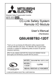
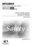
2.4 Confirming Production Information
The production information of the QS0J65BTS2-4T can be confirmed on
the rating plate located on the side of the module.
PASSED
MODEL QS0J65BTS2-4T
Model name
TECH.VER.A
SERIAL 000000000000000-A
Module technical version
Production information
Standard symbol for
conformance is described.
80M1 IND.CONT.EQ.
CLASS2 ONLY
MADE IN JAPAN
2.5 Safety Standards
Normes de sécurité
Use the product according to the following safety standards.
Region
International
Europe
North America
Safety Standards
IEC61508 Parts 1-7:1998-2000, ISO13849-1:2006,
IEC61131-2:2007, IEC61000-6-2:2005, IEC61000-6-4:2006,
IEC61784-3:2010, IEC60204-1:2006
EN954-1:1996, EN ISO13849-1:2008, EN61131-2:2007,
EN61000-6-2:2005, EN61000-6-4:2007
UL508, NFPA79-2007
6
Utiliser le produit dans le respect des normes de sécurité suivantes.
Région
International
Europe
Amérique du
Nord
Normes de sécurité
IEC61508 Parts 1-7:1998-2000, ISO13849-1:2006,
IEC61131-2:2007, IEC61000-6-2:2005, IEC61000-6-4:2006,
IEC61784-3:2010, IEC60204-1:2006
EN954-1:1996, EN ISO13849-1:2008, EN61131-2:2007,
EN61000-6-2:2005, EN61000-6-4:2007
UL508, NFPA79-2007
2.6 Module Replacement
Replace the module according to the following replacement cycle.
Module
Replacement Cycle
CC-Link Safety system remote I/O module
7
5 years
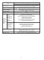
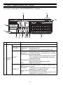
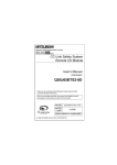
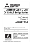
3. PART NAMES AND SETTINGS
The name of each part in the QS0J65BTS2-4T is shown.
1)
1)
10)
8)
10)
2) 6) 3) 5) 4) 9)
No.
Name
Description
LED name
1)
Indicator
LEDs
7)
Indication
"POWER"
Indicates the power status of the safety remote I/O module.
ON (green) : Normally powered
OFF
: Powered off or error occurred (blown fuse)
"RUN"*1
Indicates the operating status of the safety remote I/O module.
ON (green) : Normally operating, or moderate error occurred
Flashing at 500ms-intervals (green)
: Switch setting has been registered but not fixed
yet or reading of error history data have been
completed normally.
Flashing at 100ms-intervals (green)
: Setting has been registered normally.
OFF
: Major error occurred
"SAFETY"*1
Indicates the CC-Link Safety system connection status of the
safety remote I/O module.
ON (green) : Connected to CC-Link Safety system*2, or selfloopback test completed normally
Flash (green): Self-loopback test in execution
OFF
: Not connected to CC-Link Safety system, or selfloopback test completed in error
8
No.
1)
Name
Description
"ERR."*1
Indicates failure or error status of the safety remote I/O module.
ON (red)
: Major error occurred, or self-loopback test
completed in error
"RUN" LED OFF: Major error occurred
Flashing at 500ms-intervals (red)
: Moderate error occurred or reading of error
history data have been completed abnormally.
Flashing at 100ms-intervals (red)
: The registered switch setting differs from the
actual switch setting.
OFF
: Normally operating
"L RUN"
Indicates the communication status of the safety remote I/O
module in the CC-Link Safety system.
ON (green) : Normally communicating in the CC-Link Safety
system
OFF
: Communication failure in the CC-Link Safety
system (Timeout error)
"L ERR."
Indicates the communication error status of the safety remote I/O
module in the CC-Link Safety system.
ON (red)
: Value set by link ID, station No, or transmission
setting switch is out of range
Flash regularly (red)
: Setting of link ID, station No, and/or transmission
setting switch is different from that of the internal
nonvolatile memory
Flash irregularly (red)
: Wrong terminal resistor setting, or noise influence
OFF
: Normally operating
"SD"
Indicates the sending status of the safety remote I/O module in
the CC-Link Safety System.
ON (green) : Data being sent
"RD"
Indicates the receiving status of the safety remote I/O module in
the CC-Link Safety System.
ON (green) : Data being received
"Y0" to "Y3"
Indicates the Output status of the safety remote I/O module.
ON (red)
: Output ON
OFF
: Output OFF
Indicator
LEDs
Setting
0 to 7
2)
Link ID setting switch*4
Description
Link ID setting
EL
Setting for reading error logs
LBT
Setting for self-loopback test
To refresh the switch setting, perform the reset operation or turn
the power OFF
ON of the safety remote I/O module.
9
No.
3)
4)
Name
Station No. setting
switch*4
Transmission speed
setting switch*4
Description
Set station No. of the safety remote I/O module within a range
from 0 to 64.*3
• Tens place of station No. is set by
X10.
• Units place of station No. is set by
X1.
Setting
Transmission speed
0
156kbps
1
625kbps
2
2.5Mbps
3
5Mbps
4
10Mbps
Always set this switch within a range of 0 to 4.
5)
Setting saving switch*4
Saves the values set by switches 2) to 4) into the nonvolatile
memory inside the safety remote I/O module.
6)
Reset switch*4
Resets the hardware of the safety remote I/O module.
7)
I/O terminal block
Two-piece spring clamp terminal block for connection of external
power supply and I/O signals.
8)
Power supply,
transmission terminal
block
Two-piece terminal block for connection of module power supply
and transmission signal.
9)
Hook for DIN rail
Hook used for installing the module to a DIN rail.
Press the center part of the hook until a click is heard.
10)
Mounting hole for
screw installation
A hole used when installing a module directly to a panel.
*1 Although the "RUN", "SAFETY" and "ERR." LEDs momentarily turn
on immediately after power ON or reset, it does not mean any fault.
*2 The "SAFETY" LED is off when no safety remote I/O station
parameters have been received during connection to the CC-Link
Safety system.
*3 Duplicate station number setting is not allowed.
*4 For the switch setting methods, refer to the CC-Link Safety system
Remote I/O Module User's Manual.
10
4. MOUNTING AND INSTALLATION
4.1 Handling Precautions
This section provides handling precautions for use of the safety remote
I/O module.
(1) Do not drop the safety remote I/O module or apply any strong impact
to it.
(2) Do not remove the printed circuit board (PCB) of the safety remote
I/O module from the case.
Doing so may cause failure.
(3) Carefully prevent any dust or wiring chips from entering the safety
remote I/O module.
Failure to do so may cause a fire, failure, or malfunction.
(4) When installing the safety remote I/O module to a control panel,
provide clearance of at least 60mm between the module's top/
bottom and any other structure or component to ensure proper
airflow and to make module replacement easy.
(5) Install the safety remote I/O module to a flat surface.
If it is not flat, an excess force may be applied to the PCB, causing
failure.
(6) Tighten the module mounting screws and terminal screws within the
following torque range.
Overtightening may result in damage to the screws or the module
case.
Serrer les vis de fixation du module et les vis de borne dans les
limites du couple de serrage prescrit.
Un serrage excessif peut endommager les vis ou le boîtier du
module.
Screw
Specified torque range
Module mounting screw (M4 screw with plain washer
finished round)
0.824 to 1.110N•m
Terminal screw (M3 screw)
Vis de borne (Vis M3)
0.425 to 0.525N•m
0,425 à 0,525 N•m
2-piece terminal block mounting screw (M3.5 screw)
0.680 to 0.920N•m
11
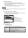
(7) When using a DIN rail, pay attention to the following:
(a) Applicable DIN rail model (conforming to IEC 60715)
TH35-7.5Fe
TH35-7.5Al
(b) Installation screw intervals
Tighten the screws at pitches of 200mm (7.88 inch) or less.
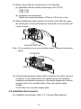
(8) When installing the safety remote I/O module to the DIN rail, press
the center part of the hook located on the bottom of the module until
a click is heard.
DIN rail
Hook for DIN rail
Note: Do not press the front face as shown below. Doing so may cause
failure.
Front face
DIN rail
(9) If the mechanical power supply switch is used for the safety remote I/
O module, in rare cases it does not operate, when the excessive
chattering is generated at power-on, and safety diagnostics function
operates due to the unstable status of the input power supply
voltage.
In this case, turn on power supply again.
4.2 Installation Environment
For installation environment, refer to "2.1 General Specifications".
12
5. WIRING
5.1 Precautions for Handling CC-Link Dedicated Cables
This section explains how to handle CC-Link dedicated cables.
Do not perform any of the following, as each of them will damage
CC-Link dedicated cables:
• Compressing the cable with a sharp object
• Twisting the cable excessively
• Pulling the cable too hard (exceeding the allowable tension)
• Stepping on the cable
• Placing an object on the cable
• Scratching the cable sheath
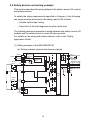
5.2 Connecting CC-Link Dedicated Cables
Raccordement des câbles dédiés CC-Link
The following figure shows how safety remote I/O modules are
connected with CC-Link dedicated cables.
La figure ci-après illustre la méthode de raccordement des modules E/S
distants de sécurité par câbles dédiés CC-Link.
Safety master module
Terminating
resistor
Safety remote
I/O module
(Blue)
DA
(White)
DB
(Yellow)
DG
SLD
CC-Link
FG
dedicated cable
English
DA
DB
DG
SLD
FG
Safety remote
I/O module
DA
Terminating
DB
resistor
CC-Link
dedicated cable
French
DG
SLD
FG
English
French
Safety master
module
Module maître de
sécurité
Blue
Bleu
Safety remote I/O
module
Module E/S de
sécurité distant
White
Blanc
Terminating
resistor
Résistance
d'extrémité
Yellow
jaune
CC-Link dedicated Câble dédié pour
cable
CC-Link
13
POINT
1)Connect the shielded wire of the CC-Link dedicated cable to SLD
terminal of each module, and ground both ends to the protective
ground connectors via FG terminals.
The SLD and FG terminals are connected inside the module.
2)Always connect terminating resistors to the modules located on both
ends of the data link network.
Connect a terminating resistor between DA and DB terminals.
1)Raccorder le fil de blindage du câble dédié CC-Link à la borne SLD
de chaque module et mettre les deux extrémités à la masse sur les
connecteurs de mise à la terre via les borne FG.
Les bornes SLD et FG sont raccordées à l'intérieur du module.
2)Toujours placer des résistances d'extrémité sur les modules placés
aux deux extrémités de la liaison de données.
Raccorder une résistance d'extrémité entre les bornes DA et DB.
14
5.3 Precautions for Wiring Module Power Supply
When wiring the module power supply of the safety remote I/O module,
note the following.
• Cable length of the module power supply must be within 10m
(32.81 ft.).
5.4 Precautions for Wiring Safety Devices
This section describes the precautions for wiring to each safety device.
(1) Wiring of the output terminal section
Use sink outputs in combination with source outputs.
Combinations of two sink outputs or single use of sink output is not
allowed.
24GDC
MC
24GDC
COM-
24VDC
Sink output
Y0L
MC
Safety remote
I/O module
24GDC
15
Sink output
Y1- L
MC
COM+
L
Safety remote
I/O module
Source
output
Y1+
MC
L
Sink
output
Y0-
Source output
Y0+
24VDC
L
Safety remote
I/O module
Safety relay
Source output
Y0+
24VDC
5.5 Safety devices and wiring example
This section describes the wiring between the safety remote I/O module
and safety devices.
To satisfy the wiring requirements specified in Category 4, the following
two points must be executed in the safety remote I/O module.
• Double input/output wiring
• Execution of the self-diagnostic function (dark test)
The following shows an example of wiring between the safety remote I/O
module and the safety device to meet the above points.
For details on the wiring with safety devices, refer to the "Safety
Application Guide".
(1) Wiring example of the QS0J65BTS2-4T
(a) Wiring example (source and source outputs)
I/O24V
24VDC
I/O24G
Safety
relay
Y0+
14C
15C
Reserve
connection
protection
circuit
16C
17C
2A
1000V
+24V
Insulation
Voltage
conversion
circuit
Y1+
24G
1
2
3
4
6
Internal
circuit
Safety
relay
+24V
7
2000V
GND
Y0- 4A
Load
5
5VDC
6A
Y1- 8A
COM2C
COM- 13C
16
24VDC
CC-Link
dedicated cable
DA
DB
DG
SLD
FG
CC-Link terminal
1
3
5
7
DA DG +24V 24G
2
4
6
DB SLD FG
Terminal block
No.
Line C
1
Empty
Line B
Line A
Empty
2
Y0+
3
Empty
4
Y0-
5
Empty
6
7
8
Y1+
Empty
COM-
Y1-
9
Empty
Empty
10
Y2+
11
Empty
12
Y2-
13
Empty
14
15
16
17
Y3+
I/O24V
Empty
Y3-
I/O24G
Empty
17
47
(1.85)
44
(1.73)
74.5
(2.93)
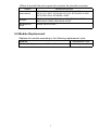
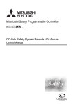
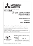
6. EXTERNAL DIMENSIONS
Mounting pitch 188.4
(7.42)
197
(7.76)
4.5
(0.18)
32.5
(1.28)
Mounting pitch 56
(2.20)
65
(2.56)
2- 4.5(0.18) mounting hole
9 (0.35)
(M4 mounting screw)
DIN rail center
Unit: mm (inch)
18
7. PRECAUTIONS FOR USE
Users must prove that their entire safety system complies with the safety
standards and the Machinery Directive. The third-party certification
organization will validate the safety of product for the entire safety system,
including a safety programmable controller and safety components.
To establish a safety system, calculate the target failure measure (PFD/PFH)
for each safety application (safety function) based on the PFD/PFH values of
the safety programmable controller and connected safety components. The
target failure measure (PFD/PFH) is the reliability target value for each
Safety Integrity Level (SIL) defined in IEC61508 and can be calculated by the
following formula.
PFD/PFH = A + B + C + D ....Calculation formula of PFD/PFH
Variable
A
B
B1
B2
C*1
D*1
Definition
Total PFD/PFH of the safety CPU module, safety power supply module,
safety main base unit, and CC-Link Safety system master module
PFD/PFH of the CC-Link Safety system remote I/O module
(1) When safety input device(s) and safety output device(s) are connected
to the same CC-Link Safety system remote I/O module: B=B1
(2) When safety input device(s) and safety output device(s) are connected
to different CC-Link Safety system remote I/O modules: B=B1+B2
PFD/PFH of the CC-Link Safety system remote I/O module to which safety
input device(s) is connected
PFD/PFH of the CC-Link Safety system remote I/O module to which safety
output device(s) is connected
PFD/PFH of safety input device(s)
PFD/PFH of safety output device(s)
*1 For the values, refer to the manual for the safety component used.
The following tables show the PFD/PFH values for the safety remote I/O
module.
Module
PFD
PFD/PFH of the QS0J65BTBS2-4T
1.68
19
10-5
PFH(/h)
7.46
10-10
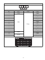
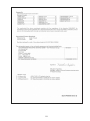
8. EC DECLARATION OF CONFORMITY FOR MACHINERY
DIRECTIVE
20
21
MEMO
22
WARRANTY
Please confirm the following product warranty details before using this product.
1. Limited Warranty and Product Support.
a.Mitsubishi Electric Company ("MELCO") warrants that for a period of eighteen (18)
months after date of delivery from the point of manufacture or one year from date of
Customer's purchase, whichever is less, Mitsubishi MELSEC Safety programmable logic
controllers (the "Products") will be free from defects in material and workmanship.
b.At MELCO's option, for those Products MELCO determines are not as warranted, MELCO
shall either repair or replace them or issue a credit or return the purchase price paid for
them.
c.For this warranty to apply:
(1) Customer shall give MELCO (i) notice of a warranty claim to MELCO and the
authorized dealer or distributor from whom the Products were purchased, (ii) the
notice shall describe in reasonable details the warranty problem, (iii) the notice shall
be provided promptly and in no event later than thirty (30) days after the Customer
knows or has reason to believe that Products are not as warranted, and (iv) in any
event, the notice must given within the warranty period;
(2) Customer shall cooperate with MELCO and MELCO's representatives in MELCO's
investigation of the warranty claim, including preserving evidence of the claim and its
causes, meaningfully responding to MELCO's questions and investigation of the
problem, grant MELCO access to witnesses, personnel, documents, physical
evidence and records concerning the warranty problem, and allow MELCO to
examine and test the Products in question offsite or at the premises where they are
installed or used; and
(3) If MELCO requests, Customer shall remove Products it claims are defective and ship
them to MELCO or MELCO's authorized representative for examination and, if found
defective, for repair or replacement. The costs of removal, shipment to and from
MELCO's designated examination point, and reinstallation of repaired or replaced
Products shall be at Customer's expense.
(4) If Customer requests and MELCO agrees to effect repairs onsite at any domestic or
overseas location, the Customer will pay for the costs of sending repair personnel and
shipping parts. MELCO is not responsible for any re-commissioning, maintenance, or
testing on-site that involves repairs or replacing of the Products.
d.Repairs of Products located outside of Japan are accepted by MELCO's local authorized
service facility centers ("FA Centers"). Terms and conditions on which each FA Center
offers repair services for Products that are out of warranty or not covered by MELCO's
limited warranty may vary.
e.Subject to availability of spare parts, MELCO will offer Product repair services for (7)
years after each Product model or line is discontinued, at MELCO's or its FA Centers'
rates and charges and standard terms in effect at the time of repair. MELCO usually
produces and retains sufficient spare parts for repairs of its Products for a period of seven
(7) years after production is discontinued.
f. MELCO generally announces discontinuation of Products through MELCO's Technical
Bulletins. Products discontinued and repair parts for them may not be available after their
production is discontinued.
23
2. Limits of Warranties.
a.MELCO does not warrant or guarantee the design, specify, manufacture, construction or
installation of the materials, construction criteria, functionality, use, properties or other
characteristics of the equipment, systems, or production lines into which the Products
may be incorporated, including any safety, fail-safe and shut down systems using the
Products.
b.MELCO is not responsible for determining the suitability of the Products for their intended
purpose and use, including determining if the Products provide appropriate safety
margins and redundancies for the applications, equipment or systems into which they are
incorporated.
c.Customer acknowledges that qualified and experienced personnel are required to
determine the suitability, application, design, construction and proper installation and
integration of the Products. MELCO does not supply such personnel.
d.MELCO is not responsible for designing and conducting tests to determine that the
Product functions appropriately and meets application standards and requirements as
installed or incorporated into the end-user's equipment, production lines or systems.
e.MELCO does not warrant any Product:
(1) repaired or altered by persons other than MELCO or its authorized engineers or FA
Centers;
(2) subjected to negligence, carelessness, accident, misuse, or damage;
(3) improperly stored, handled, installed or maintained;
(4) integrated or used in connection with improperly designed, incompatible or defective
hardware or software;
(5) that fails because consumable parts such as batteries, backlights, or fuses were not
tested, serviced or replaced;
(6) operated or used with equipment, production lines or systems that do not meet
applicable and commensurate legal, safety and industry-accepted standards;
(7) operated or used in abnormal applications;
(8) installed, operated or used in contravention of instructions, precautions or warnings
contained in MELCO's user, instruction and/or safety manuals, technical bulletins and
guidelines for the Products;
(9) used with obsolete technologies or technologies not fully tested and widely accepted
and in use at the time of the Product's manufacture;
(10)subjected to excessive heat or moisture, abnormal voltages, shock, excessive
vibration, physical damage or other improper environment; or
(11)damaged or malfunctioning due to Acts of God, fires, acts of vandals, criminals or
terrorists, communication or power failures, or any other cause or failure that results
from circumstances beyond MELCO's control.
f. All Product information and specifications contained on MELCO's website and in
catalogs, manuals, or technical information materials provided by MELCO are subject to
change without prior notice.
g.The Product information and statements contained on MELCO's website and in catalogs,
manuals, technical bulletins or other materials provided by MELCO are provided as a
guide for Customer's use. They do not constitute warranties and are not incorporated in
the contract of sale for the Products.
h.These terms and conditions constitute the entire agreement between Customer and
MELCO with respect to warranties, remedies and damages and supersede any other
understandings, whether written or oral, between the parties. Customer expressly
acknowledges that any representations or statements made by MELCO or others
concerning the Products outside these terms are not part of the basis of the bargain
between the parties and are not factored into the pricing of the Products.
i. THE WARRANTIES AND REMEDIES SET FORTH IN THESE TERMS ARE THE
EXCLUSIVE AND ONLY WARRANTIES AND REMEDIES THAT APPLY TO THE
PRODUCTS.
j. MELCO DISCLAIMS THE IMPLIED WARRANTIES OF MERCHANTABILITY AND
FITNESS FOR A PARTICULAR PURPOSE.
24
3. Limits on Damages.
a.MELCO'S MAXIMUM CUMULATIVE LIABILITY BASED ON ANY CLAIMS FOR BREACH
OF WARRANTY OR CONTRACT, NEGLIGENCE, STRICT TORT LIABILITY OR OTHER
THEORIES OF RECOVERY REGARDING THE SALE, REPAIR, REPLACEMENT,
DELIVERY, PERFORMANCE, CONDITION, SUITABILITY, COMPLIANCE, OR OTHER
ASPECTS OF THE PRODUCTS OR THEIR SALE, INSTALLATION OR USE SHALL BE
LIMITED TO THE PRICE PAID FOR PRODUCTS NOT AS WARRANTED.
b.Although MELCO has obtained the certification for Product's compliance to the
international safety standards IEC61508 and EN954-1/ISO13849-1 from TUV Rheinland,
this fact does not guarantee that Product will be free from any malfunction or failure. The
user of this Product shall comply with any and all applicable safety standard, regulation or
law and take appropriate safety measures for the system in which the Product is installed
or used and shall take the second or third safety measures other than the Product.
MELCO is not liable for damages that could have been prevented by compliance with any
applicable safety standard, regulation or law.
c.MELCO prohibits the use of Products with or in any application involving power plants,
trains, railway systems, airplanes, airline operations, other transportation systems,
amusement equipments, hospitals, medical care, dialysis and life support facilities or
equipment, incineration and fuel devices, handling of nuclear or hazardous materials or
chemicals, mining and drilling, and other applications where the level of risk to human life,
health or property are elevated.
d.MELCO SHALL NOT BE LIABLE FOR SPECIAL, INCIDENTAL, CONSEQUENTIAL,
INDIRECT OR PUNITIVE DAMAGES, FOR LOSS OF PROFITS, SALES, OR
REVENUE, FOR INCREASED LABOR OR OVERHEAD COSTS, FOR DOWNTIME OR
LOSS OF PRODUCTION, FOR COST OVERRUNS, OR FOR ENVIRONMENTAL OR
POLLUTION DAMAGES OR CLEAN-UP COSTS, WHETHER THE LOSS IS BASED ON
CLAIMS FOR BREACH OF CONTRACT OR WARRANTY, VIOLATION OF STATUTE,
NEGLIGENCE OR OTHER TORT, STRICT LIABILITY OR OTHERWISE.
e.In the event that any damages which are asserted against MELCO arising out of or
relating to the Products or defects in them, consist of personal injury, wrongful death and/
or physical property damages as well as damages of a pecuniary nature, the disclaimers
and limitations contained in these terms shall apply to all three types of damages to the
fullest extent permitted by law. If, however, the personal injury, wrongful death and/or
physical property damages cannot be disclaimed or limited by law or public policy to the
extent provided by these terms, then in any such event the disclaimer of and limitations on
pecuniary or economic consequential and incidental damages shall nevertheless be
enforceable to the fullest extent allowed by law.
f. In no event shall any cause of action arising out of breach of warranty or otherwise
concerning the Products be brought by Customer more than one year after the cause of
action accrues.
g.Each of the limitations on remedies and damages set forth in these terms is separate and
independently enforceable, notwithstanding the unenforceability or failure of essential
purpose of any warranty, undertaking, damage limitation, other provision of these terms or
other terms comprising the contract of sale between Customer and MELCO.
25
4. Delivery/Force Majeure.
a.Any delivery date for the Products acknowledged by MELCO is an estimated and not a
promised date. MELCO will make all reasonable efforts to meet the delivery schedule set
forth in Customer's order or the purchase contract but shall not be liable for failure to do
so.
b.Products stored at the request of Customer or because Customer refuses or delays
shipment shall be at the risk and expense of Customer.
c.MELCO shall not be liable for any damage to or loss of the Products or any delay in or
failure to deliver, service, repair or replace the Products arising from shortage of raw
materials, failure of suppliers to make timely delivery, labor difficulties of any kind,
earthquake, fire, windstorm, flood, theft, criminal or terrorist acts, war, embargoes,
governmental acts or rulings, loss or damage or delays in carriage, acts of God, vandals
or any other circumstances reasonably beyond MELCO's control.
5. Choice of Law/Jurisdiction.
These terms and any agreement or contract between Customer and MELCO shall be
governed by the laws of the State of New York without regard to conflicts of laws. To the
extent any action or dispute is not arbitrated, the parties consent to the exclusive
jurisdiction and venue of the federal and state courts located in the Southern District of the
State of New York. Any judgment there obtained may be enforced in any court of
competent jurisdiction.
6. Arbitration.
Any controversy or claim arising out of, or relating to or in connection with the Products,
their sale or use or these terms, shall be settled by arbitration conducted in accordance
with the Center for Public Resources (CPR) Rules for Non-Administered Arbitration of
International Disputes, by a sole arbitrator chosen from the CPR's panels of distinguished
neutrals. Judgment upon the award rendered by the Arbitrator shall be final and binding
and may be entered by any court having jurisdiction thereof. The place of the arbitration
shall be New York City, New York. The language of the arbitration shall be English. The
neutral organization designated to perform the functions specified in Rule 6 and Rules
7.7(b), 7.8 and 7.9 shall be the CPR.
26
Country/Region Sales office/Tel
Country/Region Sales office/Tel
USA
Mitsubishi Electric Automation lnc.
500 Corporate Woods Parkway, Vernon
Hills, IL 60061, USA
Tel : +1-847-478-2100
South Africa
CBI-Electric.
Private Bag 2016, ZA-1600 Isando,
South Africa
Tel : +27-11-977-0770
Brazil
MELCO-TEC Representacao Comercial
e Assessoria Tecnica Ltda.
Av. Paulista, 1439, cj74, Bela Vista,
Sao Paulo CEP: 01311-200-SP Brazil
Tel : +55-11-3146-2200
China
Mitsubishi Electric Automation (China) Ltd.
No.1386 Hongqiao Road, Mitsubishi
Electric Automation Center, Changning
District, Shanghai, China
Tel : +86-21-2322-3030
Germany
Mitsubishi Electric Europe B.V. German
Branch
Gothaer Strasse 8, D-40880 Ratingen,
Germany
Tel : +49-2102-486-0
Taiwan
Setsuyo Enterprise Co., Ltd.
6F., No.105, Wugong 3rd Road, Wugu
District, New Taipei City 24889, Taiwan,
R.O.C.
Tel : +886-2-2299-2499
UK
Mitsubishi Electric Europe B.V. UK Branch
Travellers Lane, Hatfield, Hertfordshire,
AL10 8XB, UK.
Tel : +44-1707-27-6100
Korea
Italy
Mitsubishi Electric Europe B.V. Italian
Branch
Viale Colleoni 7-20864 Agrate Brianza
(Milano), Italy
Tel : +39-039-60531
Mitsubishi Electric Automation
Korea Co., Ltd.
3F, 1480-6, Gayang-Dong, Gangseo-Gu,
Seoul, 157-200, Korea
Tel : +82-2-3660-9530
Singapore
Mitsubishi Electric Europe B.V. Spanish
Branch
Carretera de Rubi 76-80.AC.420, E-08190
Sant Cugat del Valles (Barcelona), Spain
Tel : +34-93-565-3131
Mitsubishi Electric Asia Pte, Ltd. Industrial
Division
307, Alexandra Road, Mitsubishi Electric
Building, Singapore, 159943
Tel : +65-6470-2308
Thailand
Mitsubishi Electric Automation (Thailand)
Co., Ltd.
Bang-Chan Industrial Estate No.111
Soi Serithai 54,
T.Kannayao, A.Kannayao, Bangkok
10230 Thailand
Tel : +66-2906-3238
Indonesia
P. T. Autoteknindo Sumber Makmur
Muara Karang Selatan, Block A / Utara
No.1 Kav. No. 11,
Kawasan Industri Pergudangan,
Jakarta-Utara 14440, P.O, Box 5045,
Indonesia
Tel : +62-21-663-0833
India
Mitsubishi Electric India Pvt. Ltd.
2nd Floor, Tower A & B, Cyber Greens,
DLF Cyber City, DLF Phase-III,
Gurgaon-122002 Haryana, India
Tel : +91-124-463-0300
Australia
Mitsubishi Electric Australia Pty. Ltd.
348 Victoria Road PO BOX11,
Rydalmere, N.S.W 2116, Australia
Tel : +61-2-9684-7777
Spain
France
Mitsubishi Electric Europe B.V. French
Branch
25, Boulevard des Bouvets, F-92741
Nanterre Cedex, France
Tel : +33-1-5568-5568
Czech Republic Mitsubishi Electric Europe B.V.-o.s.Czech
office
Avenir Business Park, Radicka 751/113e,
158 00 Praha5, Czech Republic
Tel : +420-251-551-470
Poland
Mitsubishi Electric Europe B.V. Polish
Branch
ul. Krakowska 50, 32-083 Balice, Poland
Tel : +48-12-630-47-00
Russia
Mitsubishi Electric Europe B.V. Russian
Branch St.Petersburg office
Piskarevsky pr. 2, bld 2, lit "Sch", BC
"Benua", office 720; 195027,
St. Petersburg, Russia
Tel : +7-812-633-3497
HEAD OFFICE : TOKYO BUILDING, 2-7-3 MARUNOUCHI, CHIYODA-KU, TOKYO 100-8310, JAPAN
NAGOYA WORKS : 1-14, YADA-MINAMI 5-CHOME, HIGASHI-KU, NAGOYA, JAPAN
When exported from Japan, this manual does not require application to the Ministry
of Economy, Trade and Industry for service transaction permission.
Specifications subject to change without notice.