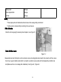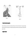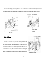
1
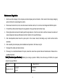
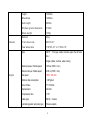
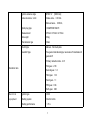
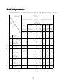
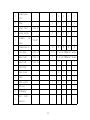
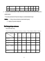
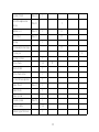
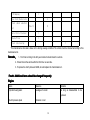
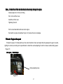
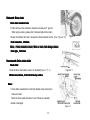
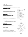
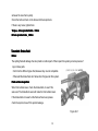
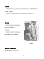
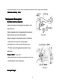
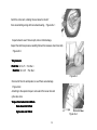
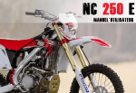
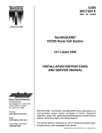
User
User’’s Safety Statement
Dear customer, please don’t ride the motorcycle before you are not reading this handbook or unknown this
motorcycle performance, also don’t borrow to anybody who don’t know how to use.
Driver’s attention:
1、Before driving
1 Check motorcycle condition careful,don’t ride if get ill; ②Don’t ride when feel sick or take medicine;③Strickly prohibit drunk driving and
driving without linence; ④Be sure to wear the protective equipment ;
⑥ The driver must be adults over the age 18。
2、In the drive
1 This vehicle not belongs to on-road type, please don’t ride on the street;
2
Keep a good mood and psychological qualities, pay all attention on driving;
③Reduce the rapid acceleration and suddenly brake
times to prevent the emergencies;
3
Should slowly when driving detour road to prevent skid(Prohibit use the front brake,otherwise the vehile will easy to fly out) ;
⑥ When rainy or snowin, the ground friction is small and brake distance will be longer,the vehicle should be slowly and brake operation
should be soft to avoid locking fall down ;
1
The company reserves it’s rights to make any changes due to product updates.
Introduction
Resume……………………………………………………………………………………… P 2~P 7
1、Resume
Maintenance………………………………………………………………………………… P8~P33
2、Maintenance
El ert ri cal sch emat ics ………………………………………………………………P34
P34
3、El
Product warranty description…………………………………………………………P35
P35
4、Product
Resume
1、Resume
Maintenance rules……………1-3
Brief…………………………1-3
Lubrication system description …1-5
Fuel system description……………1-6
Front wheel / Suspension / Handle description …………1-6
Rear wheel / Suspensiondescription…………………1-7
Battery / Charging system description……………1-7
Ignition system description ……………………1-7
Cooling system description………1-6
2
Maintenance Regulation
1.
Must to use this company or this company recommend spare parts or lubricants;Not to suits to this company designing
parts or lubricants ,may damage the vehicle .
2.
Should use the metric tool, bolt, nuts and screws to maintain vehicle, it’s not can be interchanged with British system.
3.
If rebuild the vehicle should change the new gaskets, O-rings, split pins and retainer rings.
4.
When tighten bolts and nuts,first starting with the big diameter or from the inner bolts. And then increase the number of
steps by diagonal unless specified special order to tighten to the specified torque.
5.
After decomposition,should clean the spare parts in the cleaner solvent; lubricating every smooth surface before
assembly .
6.
After assembly,check all spare parts installation and operation, if all these are right.
7.
Dredge all the cables and wiring harness.
8.
Please go to our authorized dealers for repair, unless the owners have special tools and maintenance of data and is a
qualified mechanic.
Brief (Technical specification) : Motorcycle running-in period is 1000km, then at the range of 1000Km, the speed
should not exceed 50km/h.
It e m s
Me a s u r e m e n t
De s c r i p t i o n
Le n g t h
21 8 0 m m
wi d t h
83 0 m m
3
Ch a s s i s
He i g h t
12 8 0 m m
Wh e e l b a s e
14 8 6 m m
Se a t he i g h t
96 0 m m
Mi n i m u m gr o u n d cl e a r a n c e
31 0 m m
Wh o l e we i g h t
13 5 k g
Ma t e r i a l
Al l o y
Fr o n t wh e e l si z e
80 / 1 0 0 - 2 1 ’’
Re a r wh e e l si z e
11 0 / 1 0 0 - 1 8 ’’ or 11 0 / 9 0 - 1 9 ’’
Type
ZS177 ( The type number remarks upper the left axle
box )
Single cylinder, 4-stroke, water-cooling
En g i n e
Maximum power / Rotate speed
19.5 kw / 9000 r / min)
Maxmum torque / Rotate speed
23 N.m /(7000 r / min)
Idle speed
1500±100 r/min
Minimum fuel consumption
≤367g/kw.h
Bore×Stroke
77×53.6mm
Displacement
249.6 ml
Compression ratio
11.5:1
Intake type
SOHC、4 valves
Lubricating system and pump type
Pressure splash
4
Ignition advance angle
BTDC 12° [3000r/min]
Valve clearance(cold)
Intake valve: 0.03 mm
Exhaust valve: 0.05mm;
Spark plug type
CHAMR10N RG6YC
Measurement
370mm×315mm×415 mm
Net weight
30 kg
Transmission type
Chain
Clutch type
Manual、Wet muiti-plate
Gearshift type
Five gears international type, two levels of transmission 6
gears shift
Primaryr reduction ratio:2.91
First gear:2.58
Reduction ratio
Second gear:1.8
Third gear:1.33
Fouth gear:1.1
Fifth gear:0.96
Sixth gear:0.88
El e c t r i c a l
Ignition type
DCDI
eq u i p m e n t
Starting system
Electric & Kick
Starting performance
≤15 s
5
Lu b ri cati o n syst em
It e m s
Oi l br a n d : APL SJ SAE10W-40
En g i n e lu b r i c a t oi l ca p a c i t y 16 0 0 m l
Fu el syst em
It e m s
De sc r i p t i o n
Oil brand
97#
Ca p a c i t y
8. 0 L
Tan k ca p a c i t y
1. 4 L
Co ol i ng syst em
It e m s
Co o l i n g
ca p a c i t y
De s c r i p t i o n
li q u i d
Re p l a c e m e n t
1. 11 L
Di s a s s e m b l y
1. 2 0 L
Re c o m m e n d e d an t i f r e e z e
Co o l a n t or th e sa m e ma s s of et h y l e n e gl y c o l an t i f r e e z e
St a n d a r d co o l a n t co n c e n t r a t i o n
Mi x e d 1: 1 wi t h di s t i l l e d wa t e r
6
Fro n t wh eel /S usp en si on / Oper ate sp eci fi cati o n
It e m s
St a n d a r d
Ma i n t e n a n c e li m i t e d
Co o l i n g wh e e l pr e s s i o n
32 / 2 . 2 5 ( Ps i / B a r )
-
Ma x lo a d
45 5 / 2 0 6 ( Lb s / K g s )
-
Rear wh eel/ S usp en si on sp eci fi cati o n
It e m s
St a n d a r d
Ma i n t e n a n a c e li m i t e d
Co o l i n g wh e e l pr e s s i o n
32 / 2 . 2 5 ( Ps i / B a r )
-
Ma x lo a d
61 7 / 2 8 0 ( Lb s / K g s )
-
Dr i v e ch a i n
11 2 jo i n t s
-
Batt ery/ Ch arg i n g syst em
It e m s
De s c r i p t i o n
Ca p a c i t y
Ba t t e r y
12 V- 6 A h
Ma x : 0. 1 m A
Cu r r e n t co n s u m p t i o n
Vo l t a g e ( 20 /6 8 F)
0
0
Fu l l y ch a r g e d
7
13 . 0 - 1 3 . 2 V
Ig ni t io n syst em
It e m s
Sp a r k pl u g
De s c r i p t i o n
St a n d a r d
CH A M P I O N
RG 6Y C
2. Maintenance
First: Maintance date………………………………2-9
Fourteenth: Engine oil/oil filter………2-23
Second: Technique maintenace……………………2-10
Fifteenth: Engineidle speed…………2-26
Third: Racing technique maintenance………………2-12
Sixteenth: Drive chain………………2-27
Fourth: Frequently changed additional issues……2-14
Seventeenth: Drive chain slider………2-27
Fifth: Oil tube…………………………………………2-15
Eighteenth: Drive chain rotor……………2-28
Sixth: Oil filter screen ………………………………2-16
Ninteenth: Active/driven sprocket………2-28
Seventh: Accelerator operation…………………………2-17
Twentieth: Brake fluid…………………2-29
Eighth: Hot start…………………………………………2-17
Twenty-first: Brake block wear…………2-30
Nineth: Air filter…………………………………………2-18
Twenty-second: Brake system…………2-30
8
Tenth: Spark plug………………………2-19
Twenty-third: Rocker arm/Vibration coupling……2-31
Eleventh: Radiator coolant……………2-19
Twenty-fourth: Wheels/tires………………2-32
Twelfth: Cooling system…………………2-20
Twenty-fifth: Front tube bearing………… … 2-33
Thirteen: Valve clearance/Decompression device system…2-21
First: Maintenance date
Summary
1、 Before maintenance put motorcycle on the level ground .
2、 Ensure the maintenance of a well-ventilated environment .
3、 Prepare the work table(under the engine) and tools.
4、 If exhaust system not cooling enough before to disaccemble spare parts or maintenance ,it will make a serious scald.
5、 Must replace the exhaust pipe gasket when take off exhaust pipe from Engine .
6、 Must check the exhaust system for leak after installition is complete .
9
Second: Technique maintenance
I:Check and clean,adjust,if necessary lubricate or replace
Frequency
First
No matter which one
time to
Items
*
* *
*
Trip distance or Date
maintain
first
Minutes
100
600
1200
1800
2400
received
Kilometers
150
1000
2000
3000
4000
Note
Month
1
6
12
18
24
Oil-way
I
I
Fule filter screen
C
C
Accelerator
I
I
Air filter
Crankcase
breather pipe
(Note 1)
C
C
C
C
(Note 2)
I
I
I
I
I
I
I
I
Spark plug
*
C:Clean R:Replace A:Adjust L:Lubricate
Air valve
I
I
I
I
I
Machine oil
R
R
R
R
R
Oil filter
R
R
R
R
R
10
*
*
Decompression
device
Idling
Coolant fluid
*
*
I
I
I
I
I
I
I
I
I
(Note 3)
I
Cooling system
Secondary
I
I
air
system
(Note2)
R
R
R
I
I
R
R
(Note 1)
I,L
I,L:Per 500km Or 3 months
Chain slider
(Note 1)
I
I,L:Per 500km Or 3 months
Brake fluid
(Note 3)
Brake system
I
I
I
I
I
I
I
I
I
I
I
I
I
Lights
I
Clutch system
*
I
Drive chain
Brake block
*
I
I
Transmission oil
*
I
R
I
I
I
I
I
I
Side stay
I
I
F/R damping
I
I
I
I
Nuts 、 Bolts 、
I
Fasteners
11
9.
* *
Wheels/tires
I
* *
Front tube bearing
I
I
I
I
I
I
I
* Please go to our authorized dealers for repair, unless the owners have special tools and maintenance of data and is a
qualified mechanic.
* *To be safe,we recommend all of these items should go to our authorized dealers for repair .
Remarks
Remarks:
(1)
、If driving on the wet and dusty road ,should maintain frequently .
(2)、Repalce per 2 years with technique skill.
Third: Racing technique maintenance
Check all items before racing .
I:Check and clean,adjust,if necessary lubricate or replace C:Clean
Items
Frequency
Notes
About 2.5
Abouy 7.5
About 15.0
About 22.5
About 30
hours
hours
hours
hours
hours
Accelarator
I
Choke valve
I
Air filter
Crankcase
pipe
Spark plug
(Note 1)
breather
R:Replace A:Adjust L:Lubricate
C
I
I
12
Coolant fluid
Valve/Decompression
device
(Note 2)
I
(Note 4)
Machine oil
(Note 3)
Oil filter
(Note 3)
Idling
I
I
R
R
I
Piston and piston rings
R
Piston pin
R
Cooling system
I
Drive chain
I,L
Chain slider
I
Drive chain rotor
I
Active/driven sprocket
I
Brake fluid
(Note 2)
I
Brake block
I
Brake system
I
Clutch system
Control cable
Exhaust pipe/Silencer
(Note 5)
R
I
I,L
I
13
F/R Damping
I
Rear fork/ Rocker arm
Front shock absorber
oil
L
(Note 3)
R
Nuts、Bolts、Fastener
I
Wheels/Tires
I
Front tube bearing
I
This maintenance schedule is base on the driving average condition.The vehicle must be checked according to this
maintenance list .
Remarks
Remarks:
1、First time to riding in the dirty environment should clean the vehicle .
2、Should check the vehicle after the first time no-race ride .
3、If replace the clutch plate and baffle ,should replace the transmission oil .
Fourth: Additional items should be changed frequently
Engine
Items
Reasons
Remarks
Cylinder head gasket
Leakage of a crush
As long as disassemble to be
replaced
Clutch pressure plate
Abrasion or rust
14
Head gasket
Leakage
As long as disassemble to be
replaced
Right side cover sealing
Damage
As long as disassemble to be
replaced
Chassis
Items
Reason
Remarks
F/R wheels
Abrasion
Minimum tread height:8mm
F/R Brake plate
Abrasion
Minimum thickness :1mm
Assembly bolts on the frame
Strain or abrasion
Chain sliding plate
Abrasion or damage
Side guard plate
Damage
Front covering parts
Damage
Front and rear fender
Damage
Clutch handle/stay
Excessive gap or damage
Brake handle
Excessive gap or damage
Kick start bar
Excessive gap or damage
Handlebar
Deformation or fissure
The throttle handle
Damage
Grip
Damage
Shift lever
Damage
15
Brake pedal
Damage
Chain adjuster/bolts
Damage
Air filter
Damage
Notes
Notes:
·These spare parts and maintenance list are base on the average riding environment
·Vehicle must be checked strictly according to the user manual .
Fifth: Oil tuble
Check the oil tube ageing,if necessary should replace it, see Figure 5-1
Sixth: Oil filter mesh
Figure 5-1
Disassemble fuel tank: first drop the oil into container, remove the tubing,bolts and oil switch, then clean the oil filter ,ensure
the O-ring in a good condition and install it to oil switch ,re-install in reverse order with the disassemble, install the fuel
tank (Make sure there is no leakage after installation). See Figure 6-1, Figure 6-2
16
Figure 6-1
Figure 6-2
Seventh: Accelerator operation
Check the throttle grip, it should be rotate smoothly and freely return; Check the throttle cable, if it’s ageing or damage
should be replaced; If throttle operate not smoothly should lubricate the cable;The free rotation distance of adjust throttle
grip is in 3-5mm.
Eighth: Cold start
17
Check the cold start grip, if necessary lubricate it ; check the cables,if these are damaged, replaced ;Ensure the cold
start grip free travel in 2-3mm( See the Figure 8-1),tightening lock nuts and install the dust cover ( See the Figure 8-2 )
Figure 8-2
Figure 8-1
Nineth: Air Cleaner
Open the air cleaner side cover, remove the retaining bolts.Remove the
filter element from bracket, put it into clean cleaner to wash, and then get it
from that cleaner to the hot soup-sudz to wash; Clean the air filter inner room
to ensure there is no mess; When the air cleaner and filter are completely dry,
put filter to the special filter oil, use hand rubbing the filter ensure the oil can
18
be entered, squeeze the excess oil.Reinstall the air cleaner.
Notes
Notes: If the air cleaner assembly install incorrectness, the dirt
or dust will enter the engine causing the piston rings and cylinder
early period abrasion.
Tenth: Spark plug
Disassembly
Disassemble fuel tank, remove the spark plug cover from cylinder
head, disassemble spark plug,and check it to see if it is damage (See Figure
10-1).(Before disassemble,use the compression air to clean the spark plug, ensure
there is no mess enter the combustor.) According to the technique maintenance
Figure10-1
19
list to check and replace.
Check
Check the following spare parts, if necessary replacement.
·If heat guard is damaged
·If electrode is abraded
·Combustion condition、tinting;
If electrode was contaminated by carbon or other dirt,please replace the spark plug.
Rrcommended spark plug : Standard CHAMPION:RG6YC
In order to prevent damage the center electrod, use the feeler gaugeto check the spark plug clearance. Don’t adjust
thespark plug clearance. If the clearance exceed the standard, with a new spark plug replacement .
0.
mm
Spark plug clearance standard
standard:0.
0.65mm
Installation: usd hand screw the spark plug to cylinder head,and then screw the spark plug to the specified
22N.m
torque. Torque
Torque:22N.m
Eleventh: Radiator coolant
Check the coolant level before start the engine or after the engine flameout 5 minutes, if can’t see the liquid
surface,please add the recommended coolant;
Remove the cover, add the mixed liquid which mixed with distilled water and antifreeze 1:1,the distance from liquid
surface to cover is 5-10mm, then install the radiator cover .
Recommended antifreeze
antifreeze:: coolant liquid or the same qulity ethylene glycol antifreeze containing silicate
preservatives .
20
Twelfth: Cooling system
Disassemble fuel tank and radiator fan blades, and check the radiator fan blades,if those are blocked or damaged;
Make the bending fan blades straight, use compressed air or low water pressure to get rid of small insects, mud or
blockages, if the air circulation restricted radiating over 20%,should replace the radiator. (See Figure 12-1 )
Check the radiator pipe, if it gets fissure or ageing,if necessary, with a new radiator replacement;
Check all of the water pipes,clamps and hoops tightness. ( See the
Figure 12-2)
Figure12-2
Figure 12-1
Thirteenth: Valves clearance
Check valves clearance
Disassemble cylinder head cover; check and adjust the valve clearance after the engine is cooled;
Disassemble crankcase cover and O-ring.(See the Figure 13-1)
21
Figure 13-1
Rotating the magnator mark on clockwise direction to make it with the left crankcase cover scale mark on the same line,
ensure the piston on the compression stroke top dead center.
Otherwise,rotating the crankshaft one whole circle on the clockwise direction,and make the magnator mark with the left
crankcase cover scale mark on the same line again ;
Check the cam sprocket indicatrix, make it with the camshaft bracket“_”mark on the same line(Figure13-2)
Figure 13-2
22
Intake side
side:
Put the feeler gague between the rocker arm stud and valve, measure the
intake side valve clearance
Intake valve clearance : 0.03mm (Figure 13-3)
Figure13-3
Exhaust valve side
side:
Put the feeler gague between the rocker arm stud and valve,measure the
exhaust side valve clearance
0.05mm
Exhaust valve clearance
clearance:0.05mm
0.05mm(Figure13-4)
Figure 13-4
Rotating the crankshaft a few times on the clockwise direction,make the crankshaft to piston compression top dead
center,check the valve clearance .
Put the O-Ring on the crankshaft timing screw with oil( check the O-Ring,if necessary with a new O-Ring replacement),
Put the grease on Crankshaft hole cap thread .
Install the crankshaft hole cap and screw it to the special torque.
15N.m
Torque
Torque:15N.m
23
Engine oil / oil filter
Fourteenth
Fourteenth:Engine
Oil surface inspection
Starting engine idling 3 minutes, waiting 3 minutes after the engine flameout .
Put the motorcycle vertical support in the horizontal plane, if the oil horizontal plane is low or close to the low level of the
oil ruler line, through the filling hole add the recommended engine oil to a third above the horizontal line.(Figure14-1)
Figure14-1
Figure14-2
API SJ
Recommended engine oil
oil:API
4-stroke oil containing the molybdenum additives or the similar higher-lever
engine oil
MA or MB
JASO T 903 Standard
Standard:MA
SAE 10W-40
Viscosity
Viscosity:SAE
24
1.6L
Fuel capacity
capacity:1.6L
1.6L(Figure14-2)
Engine oil and oil filter replacement
Remove the engine cover,
Starting engine idling 3 minutes,
Figure14-3
Waiting 3 minutes after engine flameout.
put motorcycle vertical support in the horizontal plane,
Stop the engine,
Remove the oil nut off(Figure 14-3)
Motorcycle on a level surface to ensure complete drainage clean.
Put an oil pan under the engine to access oil,
Remove the engine oil drain bolt and aluminum gasket,
Drop the engine oil completely(Figure 14-4)
After close the engine stop switch,
Kick the engine start lever 5 times or more times.
Figure14-4
25
This menthod can drop the engine oil completely
Remove the bolts, oil filter cover and O-Ring( Figure 14-5 )
Figure 14-5
Remove the oil filter(Figure14-6),
Figure14-6
Install the engine oil drain screw, use the special Torque 20N.m to tightening the engine drain bolt(Figure 14-3).
26
If install the oil filter anti-direction,it will seriously damage the engine,
Notes
Notes:If
Grease engine oil on the new O-Ring,
Put it on the oil filter cover,
Install the oil filter cover
Tightening the bolt.
Put the recommended machine oil enter engine :
Re-check the engine oil level(See Figure 14-1) ensure there is no leakage.
Fifteenth: Engine idle speed
Preheat the engine 10 minutes after use the correct method to check and adjust the idle speed,put the gear in neutral,
righting the vehicle, according to the specification to install the counter,adjusting the bolt to make a suitable idling speed .
(Figure 15)
1500
+100rpm
Idel speed
speed:1500
1500+
Idling adjusting screw
Figure 15
27
Sixteenth: Drive chain
Drive chain relaxation tests
Put the vehicle on the workbench, make the rear wheel off ground .
(When engine working, please don’t check and adjust drive chain)
Review the middle of the chain, measure the chain relaxation on this. (S e e Fi g u r e 16 )
Figure 16
25-35mm
Chain relaxation
relaxation:25-35mm
If chain relaxed too much, 50mm or more,it will damage chassis.
Notes
Notes:If
520 chain
Chain type
type:520
Seventeenth: Drive chain slider
Chain slider
Check the drive chain slider, to see if it’s abraded.(F i g u r e 17 - 1 )
Figure17-1
5.0mm from the top surface
Maintenance limited
limited:5.0mm
Notes:
If chain slider was abrade, the chain will abrade rocker, destroy the
chain and rocker.
Check the chain guide and slider, to see if these are rank well ,
abrade or damaged.
Figure17-2
28
(F i g u r e 17 - 2 )
If damaged or abraded,replace the chain guide.
If the slider was wear to the special wear marker bottom,replace the chain guide slider.
Eighteenth: Drive chain rotor
Remove the side frame, check the drive chain rotor, to see
if it’s excessed the wear or clamping stagnation.
Maintanace limited:
35mm
The minimum outside diameter of rotor
rotor:35mm
If need to replace the rotor, please screw the rotor bolts/nuts to
Figure18
the special torque.
(
“→”this mark outward to install drive chain rotor)(Figure 18)
Torque
Torque: 12N.m
Nineteenth: Drive/driven sprocket
Check the drive / driven sprocket gear, to see if these
were wear or damaged.
If necessary, replace it .(Figure 19)
Don’t install the new drive chain on the wear sprocket.
The chain and sprocket should be in good condition,otherwise it
Figure19
29
will wear the new chain quickly.
Check the bolts and nuts on the drive and driven sprockets.
If there is any loose, tighten them.
drive sprocket bolts
31N.m
Torque
Torque:drive
bolts:31N.m
Driven sprocket nuts
32N.m
nuts:32N.m
Twentieth: Brake fluid
Notes:
The spilling fluid will damage the color plastic or rubber parts. When repair this system,put some pieces of
rag on these parts.
·Don’t mix the different types fluid,because they are not compatible
·When add the brake fluid, don’t allow other things enter this system.
Fluid surface inspection
When fluid surface lower, check the brake block, to see if this
was wear. The brake block wear will make the fluid surface lower .
If the brake block not wear but the fluid surface lower, please
check the system,to see if this system leakage.
Figure 20-1
30
Front brake
brake:
Turn the hand lever to make the inspection line with the fluid level at the same line,check the front brake
fluid level.(Figure 20-1)
If the fluid level is closed to the horizontal line, check the brake block, to see if this was wear.
Rear brake
brake:
Put the motorcycle upright on the horizontal line,
inspect the rear brake fluid level.
(Figure 20-2)
If the fluid level is closed to horizontal line, please
check the brake block, to see if it was wear.
Figure20-2
Twenty-first: Brake blocl wear
Check the brake block ,to see if it was wear.
31
If any one brake plate was wear to the wear limited mark bottom, please replace the brake block .
1.0mm
Maintenance limited
limited:1.0mm
Twenty-second: Brake system
Front brake hand lever inspection
Loosing the locknut to roll the adjuster can adjust the front
brake hand lever.
Rolling the adjuster on the clockwise direction to make the
brake hand lever away from vehicle handbar;
Figure 22-1
Rolling the adjuster on anticlockwise direction to make the
brake hand lever closed to the vehicle handbar.
When adjust over, screw the locknut to special torque.
(The touch surface of adjusting bolt and piston should
add grease)
Torque
5.9N.m (Figure 22-1)
Torque:5.9N.m
If the brake hand lever free travel is exceed 20mm, the air will
enter this system, it need to discharge.
Figure22-2
Brake pedal height
32
Loosen the locknut and roll the pedal height to adjust bolt.
Adjust the brake pedal height to 79.6mm or what you need height.(Figure22-2)
Twenty-third: Rocker arm/ rocker arm fork
Put the support under engine, make the rear wheel off ground.
Catch the rocker arm, shaking left and right to check if there is
something wrong with rocker arm bearing.
(Figure 23-1)
If bearing wear excessive, replace a new one.
Inspect rocker arm fork, replace all damage needle bearing.
It should disassemble when every time works 7.5 hours,
Figure23-1
Clean,inspect rocker arm and rocker arm fork center bearing and all of the
related sealing element.
Add lubricant and reassemble.
Twenty-fourth: Wheels / tires
Put support under the engine,make the front wheel off ground,
Catch the bottom of front brake, shaking front wheel, check if there is something
wrong with the front wheel bearing;(Figure 24-1)
33
Figure24-1
Catch the rocker arm, shaking the rear wheel to check if
there is something wrong with rear wheel bearing.,(Figure 24-2)
Figure24-2
Inspect wheel to see if there is split, nails or other damage,
Inspect the cold tires pressure carefully(It should be measure when tires cold)
(Figure 24-3)
Tire pressure:
Front tire: 32 / 2 . 2 5 ( Ps i / B a r )
Rear tire: 32 / 2 . 2 5 ( Ps i / B a r )
Figure24-3
Check all of the rims and spokes, to see if there were damage
(Figure 24-4)
According to the special torque to screw all of the loose rims and
cycle valve nuts.
Torque: front wheel rim:3.68N.m
Rear wheel rim:3.7N.m
Cycle valve nut:13N.m
Figure 24-4
34
Twenty-fifth: Front tube bearing
Put the support under engine, make the front wheel off ground.
Inspect the direction hand lever to see if turning left and right flexible.(Ensure the main wire harness is not
interference the direction hand lever rotation)
If the direction hand lever rotate not smoothly, it has block or shaft radial pla, please check the front tube bearing.
If the activity clearance too large, please check the direction column nut, if the nut loose or there is a crack on the
front tube.
35
3、
Electrical element diagram
36
4、
Maintenance Warranty instruction
Dear user
user:
Thanks for using our vehicle NC250 type, in order to protect your benefits, please read this manual instruction and according to it to
use.
After-sale service
一、 Because of this vehicle NC250 special performance, from the purchase date,it will be free to repair or replace the bad quality
parts.
二、 Specific to this product using performance, the main quick-wear parts are not include to the maintenance range, the detail
quick-wear parts information as follows: out/inner tires、spoke、chain、chain upper/down slider、wire roll pull、hand lever
grip、lights、plastic parts、air filter、oil tube、water tube、clutch、fuel filter、spark plug、piston、piston ring、piston pin、
cylinder body and one set of engine gaskets etc.
Quality guarantee description
一 、 Cause of the non-normal operate to result fault is not include quality guarantee, if the fault need repair, the company or
authorized service station will take a suitable parts charge.
37
二、User should comply with this manual to maintain 、replace the quick-wear parts on schedule, if don’t do like this, all of the
damage will not include the free after-sale service; User should on schedule to maintain and the service station should record the
maintanace report actually, if don’t have this report, it’s not suit to the warranty condition.
SHANDONG ASIAWING MOTORS CO.,LTD
Address:Taian City, Shandong Province
PC:271000
Tel:0538-6366706/6366708
Fax:0538-6366702
38
Packing list
NO.
Name
Quantity
1
Handbar
1 Set
2
Front wheel assy
1 Set
3
Packing list detail:
(1)
Battery
1 Piece
(2)
Battery cable tie
1 Piece
(3)
Headlamp assy
1 Set
(4)
Headlamp install bolts
1 Set
(5)
Rear lamp assy
1 Set
(6)
Front brake shield
1 Pair
(7)
Front brake shield install bolts
1 Set
(8)
Tank cover(Left/Right)
1 Set
(9)
Rear cover(Left/Right)
1 Set
(10)
Appearance parts install bolts
1 Set
(11)
Tool:Spark plug sleeve
1 Pcs
(12)
Sticker
1 Set
(13)
Instruction book
1 book
This pa cking li st page pri nted separat ed.
39
Remarks