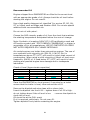
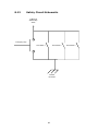
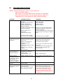
1
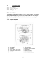
Envirostar Model ES10
Operating, Maintenance
and Spares Manual.
Envirostar Limited
PO Box27
Sheriff Hutton
York
YO60 6WZ
Phone: 08450 066099
E-mail: info@envirostar. co.uk
www.envirostar.co.uk
General information statement
ENVIROSTAR LTD has a policy of continuous product improvement
and reserves the right to modify and amend the specification and
content of the ENVIROSTAR.
The name and logo ENVIROSTAR ™ are registered trademarks.
The name ENVIROSTAR© is copyright and belongs to ENVIROSTAR
LTD.
Patents are currently pending on the ENVIROSTAR models.
Information on the Briggs and Stratton engine is reproduced by
the kind permission of Briggs and Stratton U.K.
Information contained in this manual is the property of
ENVIROSTAR LTD and is not to be reproduced without prior
permission.
For further information about ENVIROSTAR products please call
your local dealer or contact ENVIROSTAR direct:
Telephone number: 08450 066 099
E mail:
[email protected]
Website: WWW.ENVIROSTAR.CO.UK
-2-
THE ENVIROSTAR MULTI-FUNCTION MACHINE.
Contents:
1. SAFETY NOTICES & ADVISE ON SAFE USE OF MACHINE
2. CE CONFORMANCE STATEMENT.
3. ENVIRONMENTAL PROTECTION.
4. GENERAL DESCRIPTION OF FEATURES.
5. LAYOUT OF MAIN FEATURES.
6. USING
6.1.
6.2.
6.3.
6.4.
6.5.
6.6.
6.7.
6.8.
6.9.
6.10.
6.11.
THE ENVIROSTAR.
General Precautions
Fuelling, Starting & Stopping the engine
Vacuum Hose Assembly
Blower Hose Assembly
Chipper Chute
Swan Neck Output Chute
The Bagger
The Pressure Washer
The Generator
Tool Carrier Tray
Hose Carrier
7. ENGINE.
7.1.
Description
7.2.
Engine Diagram
7.3.
Storage
-3-
8. MAINTENANCE.
8.1.
Service schedule
8.2.
Engine Adjustments
8.3.
Oil Change
8.4.
Air Filter Change
8.5.
Spark Plug Change
8.6.
Removing the covers
8.7.
Fan/Chipper Drive Belts: Adjust & Replacement
8.8.
Washer Pump Drive Belt: Adjust & Replacement
8.9.
Alternator Drive Belt: Adjust & Replacement
8.10.
Replacing Access Door Micro switches
8.11.
Replacing Emergency Stop Switch
8.12.
safety Circuit Schematic
8.13.
Replacing Access Door Springs
8.14.
Chipper Blade Replacement
8.15.
Greasing the Bearings
8.16.
Trailer
9. TROUBLESHOOTING.
-4-
1:
SAFETY
The following symbols are used on the ENVIROSTAR and within
this manual:
The safety alert symbol is used to identify safety information about
hazards that can result in personal injury.
DANGER Indicates a hazard which, if not avoided, will result in death
or serious injury
WARNING Indicates a hazard which, if not avoided, will result in death
or serious injury.
CAUTION Indicates a hazard, which, if not avoided, might result in
minor, or moderate injury
Flammable Material and High Temperatures are present in the
form of fuel and exhaust gases
Biological hazard may be present in those tools and assemblies
that are involved in the movement of waste.
High voltage is present in the engine ignition circuits and the
generator
-5-
Ear protection must be worn.
Face protection must be worn.
Safety boots must be worn.
Safety gloves must be worn.
Eye protection must be worn.
Caution possibility of entrapment exists inside the power unit.
No naked lights or smoking when fuelling the engine or the burner.
Environmental Parameters for ES10.
Minimum Operating Temperature: Minus 100 C
Maximum Operating Temperature: + 400 C
Humidity range: 25 – 85% RH
Note Minimum Operating Temperature when using the pressure washer: + 40 C
Storage
Minimum Temperature: Minus 250 C
Maximum Temperature: + 450 C
Humidity Range: 20 – 95% RH
-6-
SAFE USE OF THE ENVIROSTAR
General Machine Use
Hazards:
Rotating machine parts
Flying debris
Noise
Electricity
Vibration
General
Please read the operating instructions carefully before using the machine
for the first time. Observe all safety information while operating the
machine.
Make sure that
-
you are familiar with all safety information.
all users of the machine have been made aware of and
understand the safety information
Use of the ENVIROSTAR should be restricted to authorised persons who
have been briefed on the safe use of the machine based on the user
manual, these notes and assessments of the specific work tasks, which
are to be carried out. (Note that the user manual should be carefully
consulted before use of the machine and in relation to any maintenance
work - the manual highlights specific hazards, which are not discussed in
this general safety guide.)
Children should not operate this machine.
Young persons, as defined by 94/33/EC, should be supervised. Young
persons should have their proposed scope of work made the subject to an
individual risk assessment.
Careful thought should be given where young people are to use the
machine or where lone working is involved.
Before commencing operations with the ENVIROSTAR ensure that the
proposed work site is clear of all spectators, livestock and pets, that the
unit is securely located, that the transport trailers wheels are chocked and
that all necessary personal protection equipment is being worn by all
personnel involved in the operations.
-7-
Before use the machine should be subject to a visual inspection by the
operator to ensure that all guards are in place, all fastenings are secure,
that hoses and ancillaries do not contain any residual debris from
previous work and that there are no signs of blockages or of fuel or oil
spills.
Where the machine is trailer mounted and is to be towed to the
workplace, normal road user checks of tyres, lights and security of the
trailer and any ancillaries or tools carried on it should be completed
before moving off. Where it is mounted or carried on some other
equipment it should be checked for security and to ensure that the load
conforms to road transport regulations before being taken onto public
roads.
When operating the ENVIROSTAR the power unit should always be within
the view of the operator, who should periodically monitor that the power
unit remains in a safe and stable position. Do not leave the machine
unattended with the engine running.
In most if not all modes of use, ear protection should be provided for
operators and eye protection will be needed where there is any risk from
flying debris. Footwear should be chosen to minimise risks of slipping and
to provide suitable protection to the operator’s feet (circumstances will
vary with specific work tasks).
Do not operate the power unit in a confined space or any area where
exhaust fumes may build up
No adjustments or repairs are to undertaken whilst the engine is running.
Only spares authorised by ENVIROSTAR Ltd should be used in the repair
or servicing of the ENVIROSTAR, the use of un-authorised parts will
render any warranty claims void.
All input ducts, input piping and output ducts are to be fitted and secured
before the engine is started.
All moving parts on the equipment are guarded and the engine is
automatically cut out when guards are opened. The equipment should
never be used when any of the safety devices are inoperative.
Despite the safeguards operative should never attempt to reach inside
any part of the equipment without turning off the engine and removing
the key. Operators should avoid wearing loose clothing such as ties,
scarves etc.
-8-
The Place of Work
When used at a static works site ENVIROSTAR should always be
positioned on firm level ground and should be chocked or made
secure in some other way to avoid movement as a result of
vibration or other cause. Where the machine is mounted on some
other equipment (rather than on its own trailer similar precautions
will be needed to ensure stability and to avoid unwanted movement
during use.
The machine should always be sited so that the output duct is
directed into a safe area (which is clear of workers, members of the
public or materials which might be damaged by flying debris).
Where there is any doubt that this area can be kept clear the need
for signs or barriers should be considered. The engine should only
be run in well-ventilated areas - normally outdoors.
Similar precautions may be needed to keep people clear of areas in
which hoses are being used (whether for blowing, vacuuming or
washing). Ancillary tools should never be used close to other
individuals nor should they ever be pointed at them.
If hoses or the output duct become blocked or appear to be blocked
the machine MUST be switched off before any attempt is made to
inspect or clear any part of the equipment.
Before beginning work a general inspection should be undertaken of
any areas of proposed blowing or vacuuming work for any
unexpected materials, such as metal fragments, glass, stones etc.
ENVIROSTAR will blow or vacuum most materials of this type but
risks from flying debris will be increased and additional precautions
may be needed.
The potential effect of noise and dust on others working or passing
nearby should be carefully considered.
Any spare fuel or oils, which are taken to work sites, should be
carefully stored well away from heat or ignition sources and with
smoking prohibited in such areas. Where ENVIROSTAR is to be refuelled it should be switched off and allowed to cool for a few
minutes before the cap is removed from any fuel container and fuel
is poured.
9
Use of the Vacuum
Specific hazards
Fire Hazard
Do not use the vacuum to collect materials that are on fire or
smouldering embers/ashes, etc as this may cause fire in the
machine or the collection receptacle.
Ensure that the collection receptacle is sufficiently robust to cope
with any potential puncture hazard, which may be associated with
the material, which it is proposed to collect.
It is essential that sufficient air is allowed to access the vacuum
pickup head in order that maximum efficiency is maintained.
Do not attempt to use the vacuum on loose gravel or on liquids.
Work involving animal waste/Biological Contaminants
Specific Hazards
Biological Hazards
Where the equipment is used in the disposal of animal or other
waste which may pose biological hazards specific assessments
should be undertaken and methods of work devised to ensure the
safety not only of those undertaking this work but of others who
may use, inspect or maintain the equipment.
10
Use of the Blower
Specific Hazards
Wear
Eye Protection
Flying Debris
When blowing material always wear Eye protection
Ensure that all personnel are at least 15m from the operations
Use of the Bagger
Specific Hazards
Sharp Objects
Use the appropriate filter to ensure that dust hazards are kept
within acceptable limits.
If using the ENVIROSTAR to pick up glass, cans rubbish or similar
materials, exercise extra caution when changing or handling the bag
as sharp objects may penetrate the bag.
Do not overfill the bag as the filter assembly and the output duct
may become clogged.
When handling heavy bags, ensure that the correct lifting technique
is used. If in doubt get help before attempting to lift bags and if
necessary consider using mechanical lifting aids.
11
Use of the Chipper
Specific Hazards
Machine Blockages
Wear Eye
Protection
Hazardous substances
Vibration
Wear Hand
Protection
Flying Debris
Wear Ear
Protection
Some plant material may be poisonous or may cause skin or eye
irritation. Checks may be needed before work begins. It is
suggested that skin is kept fully covered, eye protection is used and
that suitable gloves are used to protect the hands during this work.
The chipper input chute has been designed to minimise the risks of
anyone reaching moving machine parts. Operators should however
use the custom designed prodder supplied to push materials into
the cutters rather than reaching into the hopper.
Material leaving the output duct may travel up to 15m and is
capable of causing injury. Ensure that all personnel are aware of
this and keep clear of the output area and that the containment
provided is capable of arresting all debris produced by the
ENVIROSTAR.
Anti Vibration protective gloves should be worn at all times by
operators whilst feeding material into the chipper chute.
12
Use of the High Pressure Washer
Specific Hazards
High Pressure
Wear Eye Protection
Never direct the spray jet at any person or animal
Never hold a finger, or any other body part, over the high-pressure
nozzle
Never direct the spray jet at the ENVIROSTAR itself or at any
electrical equipment.
After use; release the pressure in the high-pressure hose by
operating the pistol trigger. Do not attempt to disconnect any hose
or coupling with pressure still in the hose.
When not in use disconnect the drive to the unit.
Never supply any liquid other than water to the water inlet.
Use only chemical cleaning agents (detergents) approved for power
washing, when using the chemical injection system.
Never use the chemical injection facility to introduce solvents.
eg. paint thinner.
Do not operate the pressure washer standing on ladders: Use a
platform or scaffolding
Children should not operate the pressure washer.
Wear eye protection when using the pressure washer.
Do not use the high pressure spray on vehicle tyre walls, which can
be badly damaged by the force of water.
Do not use the washer at temperatures lower than + 40 C
13
Use of the Generator
Warning
In common with all electrical equipment a risk of electrical shock
exists when using this generator. Always check and where
necessary replace power cords, plugs and equipment before
attaching them to the ENVIROSTAR.
Periodic inspection of the power outlet sockets and the overload
breaker is recommended. A qualified electrical engineer should
repair any damage immediately.
Never plug the generator directly into household circuits.
Always ensure that the ENVIROSTAR earthing point is connected to
a suitable earth.
Never operate the generator at maximum power for more than 30
minutes.
When using extension cords ensure that they are suitable for
outdoor use adequately rated and provide earth continuity.
Do not allow the ENVIROSTAR to generate electricity if it cannot be
protected from adverse weather conditions.
14
Inspection and maintenance
See Section 8 for maintenance intervals and details of items
requiring maintenance and inspection.
Additional Inspection
In addition to user checks before use (see above) routine
inspections are advised to ensure that the machine and its
ancillaries remain safe for use. The frequency of such inspections
will vary with the nature and frequency of use of the equipment but
should include:
Inspection of all guards and testing of safety cut outs
Inspection of top bolts securing the lifting points
Inspection and testing of the emergency cut off switch
Check the security and sharpness of cutting blades
At not less than weekly intervals.
15
2:
CE CONFORMANCE STATEMENT.
For all countries; using this product is subject to the approval by the
authorities concerned.
The approval appears on the label affixed to the main power unit,
on the Right side panel, to the left of the engine
The CE marking on the product certifies compliance with technical
regulations applicable at the date of approval. In accordance with
the following guidelines and standards:
The Machinery Directive 89/392/EEC
The EMC directive 89/336/EEC
The Noise Emission in the Environment by Equipment for use
Outdoors
Regulations. Statutory Instrument 2001: No 1701 as Amended by
Statutory Instrument 2001: No 3958
16
3:
ENVIRONMENTAL PROTECTION
Please remember to observe the local regulations regarding the
disposal of your packaging materials, exhausted batteries, oil, oil
filters and other items replaced during servicing. If in doubt on the
proper method of disposal please contact your local council
regarding arrangements in your area.
17
4:
GENERAL DESCRIPTION OF FEATURES
The ENVIROSTAR multi-function unit has been designed to
undertake the following tasks:
Vacuuming.
Blowing.
Pressure Washing.
Chipping.
Power Generation.
Mulching.
Bagging.
The power unit has access panels to allow fuel filling, oil level
checking, starting and the connection of the various tools.
Dimensions
Power unit:
Length - 1.2m
Trailer mounted: Length - 2.3 m
Width - 0.55 m
Width - 1.2 m
Height - 0.70 m
Height - 1.1m
Weight–300Kgs
Weight 370Kgs
Performance
Vacuum
150mm Vacuum
Maximum pull: 6Kg
Maximum flow rate: 21 m/s
Hose length: 6 m
Blower
Maximum flow 150mm hose: 26 m/s
Chipper
Maximum capacity: 65mm
Maximum Chipping Rate: 20 m/s
Bagger
Bag size 500mm wide by 800mm long, polypropylene reinforced
Easy bag and filter changing system
Power Washer
Pump type: Triplex plunger.
Pump Maximum Pressure: 100 bars.
Maximum flow: 12 L/min
18
Generator
110 or 220 Volt (factory set) 50Hz, 2.2Kva
Engine specification
Briggs And Stratton Single cylinder. Air-cooled. 9.1/2 Horsepower.
Fuel Consumption. 3.15 L/hr at full power output. Electric start.
Built in fuel gauge.
Safety Features
Centrally located, Emergency stop switch. (Panic button, Locking
type)
All entry ports are continually monitored for correct operation
All moving parts fully enclosed.
Transportation Trailer
600kg rated
Fitted with independent suspension Road or ATV tyres & all
necessary lights, wiring and plug for standard trailer socket.
Tow ball attachment or garden tractor fork and pin tow hitch.
19
5:
LAYOUT OF MAIN FEATURES
Fork Lift
Handles
Generator
Choke &
Throttle
Controls
Engine
Vacuum Input
Access Panel
Washer Pressure
Gauge
Engine Exhaust
Pressure Washer
Water Input/Output
Cleaning Agent Input
Maintenance Access
Panel for Oil & Battery
20
Vacuum &
Blower Output
Panel
Trailer
Mounting Plate
for Optional
Trailed Vacuum
Head
Generator
Frequency
Meter
Maintenance
Access Panel
21
Lever for Pump Drive
on Pressure Washer
Chipper Input
Access Panel
Washer Pressure
Adjustment
Valve
Emergency Stop
Button
Petrol Filler Cap
& Gauge
22
Generator
On/Off
Switch
6:
6.1
6.2
6.3
6.4
6.5
6.6
6.7
6.8
6.9
6.10
6.11
6.12
USING THE ENVIROSTAR
General Precautions
Fuelling, Starting and Stopping the engine
The 150mm Vacuum Hose assembly
The 150mm Blower Hose assembly
The Chipper Input Chute
The Mulcher Input Chute
The Output Swan Neck Chute
The Bagger
The Pressure Washer
The Generator
Tool Carrying Tray
Hose Carrier
6.1 General Precautions.
Warning
Before commencing operations with the ENVIROSTAR ensure that
the proposed work site is clear of all spectators, livestock and pets,
that the unit is securely located, that the transport trailers wheels
are chocked and that all necessary personal protection equipment is
being worn by all personnel involved in the operations.
It is recommended that certified ear, eye, hand and foot protection
is worn when operating the ENVIROSTAR.
When operating the ENVIROSTAR the power unit should always be
within the view of the operator, who should periodically monitor
that the power unit remains in a safe and stable position.
Warning
Do not operate the power unit in a confined space or any area
where exhaust fumes may build up.
Engines give off carbon monoxide, an odourless colourless poison
gas.
Breathing carbon monoxide can cause nausea, fainting or death.
23
Warning
Do not wear loose fitting clothing or dangling items that could
become caught.
Warning
Running engines produces heat. Engine parts, especially the
exhaust, become extremely hot.
Severe thermal burns can occur on contact.
Combustible debris, such as leaves, grass, brush, etc. can catch
fire.
Allow the exhaust, engine cylinder and fins to cool before touching.
Remove accumulated combustibles from the exhaust area and the
cylinder area.
Danger
Items leaving the output duct (or hose) do so with extreme velocity
and should be directed into a suitable containment, personnel
should be kept clear at all times.
24
6.2
Fuelling, Starting and Stopping the engine.
Warning
Take care when handling petrol. Petrol is highly inflammable and
the vapours that it gives off are explosive.
Store petrol
- in properly approved containers only
- in a room to which children have no access
- in a room that is protected from heat or sparks
Do not refill the fuel tank in an enclosed space or while the engine is
running or hot.
Clean around the fuel filler cap before removing. When filling use a
fine gauze funnel to ensure that the petrol is free of all foreign
matter.
Fill the tank to approximately 4cms (1½”) below the top of the neck
to allow for fuel expansion.
Be careful not to over fill.
Stay away from naked flames when filling the tank and do not
smoke or do anything that could generate sparks.
On completion of fuelling ensure that the engine fuel tank filler cap
is correctly replaced.
If spillage of fuel occurs ensure that all spilt fuel is removed before
continuing.
Be sure spark plug, fuel cap and air cleaner are in place. Do not
crank engine with spark plug removed.
Recommended Fuel
The engine is a four-stroke unit and requires unleaded petrol. Use
clean, fresh, Lead – free petrol with a minimum 85 octane.
Do not use fuels that contain Methanol
Do not mix oil with the petrol
25
Recommended Oil
Engines shipped from ENVIROSTAR are filled to the correct level
with an appropriate grade of oil. Always check the oil level before
starting the engine. Do not overfill.
Use a high quality detergent oil classified “for service SF, SG, SH,
SJ” or higher such as Briggs and Stratton 30W. Do not use special
additives with recommended oils.
Do not mix oil with petrol.
Choose the SAE viscosity grade of oil from the chart that matches
the starting temperature anticipated before the next oil change.
Note: Synthetic oil meeting ILSAC GF-2 API certification mark and
API service symbol with “SJ/CF ENERGY CONSERVING” or higher is
acceptable oil for all temperatures. USE OF SYNTHETIC OIL DOES
NOT ALTER REQUIRED OIL CHANGE INTERVALS.
Air-cooled engines run hotter than automotive engines. The use of
non-synthetic multi-viscosity oils (5W-30, 10W-30, Etc) in
temperatures above 4OC (400F) will result in higher than normal oil
consumption. When using a multi-viscosity oil check oil level more
frequently. SAE30 oil, if used below 4oC (400F) will result in hard
starting and possible engine bore damage due to inadequate
lubrication.
Check oil level (Approximate capacities)
Model Series
85400
1154,1174,1184
138400
185400
235400 & 245400
Litres
0.6
0.7
0.9
1.2
1.5
Quarts
5/8
3/4
1
1-1/4
1-5/8
Ounces
20
24
30
41
51
Place the ENVIROSTAR on level ground, if mounted on a trailer
ensure that the trailer is level, clean around the oil fill
Remove the dipstick and wipe clean with a clean cloth.
Insert the dipstick into the oil fill – tighten down if oil fill is High.
do not tighten down if the oil level is low
– remove the dipstick to
check the oil level.
Oil should be at the FULL mark
If oil is required, add slowly. Do not over-fill.
Tighten dipstick firmly before restarting the engine.
26
Starting
Before starting the engine check the oil level (See above)
Do not use a pressurised starting fluid.
Always start, store, use and fuel the ENVIROSTAR in a level
position.
Before Attempting to starting the ENVIROSTAR check that the
emergency stop switch has not been activated. To reset turn the
switch in the direction indicated by the arrows. Also check that the
access panel safety switches are being correctly activated. See
section 8 for further details on the safety systems
(See diagram in Section 7.2)
1.
2.
3.
4.
Move the choke control (1) to the CHOKE position.
Move the throttle control (2) to the FAST position.
Turn the fuel shut off valve (3) to the ON position.
Turn the key to the start position until the engine starts, then
release,
repeat if necessary.
5. When the engine is running shut off the choke and set the
speed to the desired RPM for the work being undertaken.
6. If the battery has become discharged and the engine will not
turn over, the engine can be started manually.
7. If engine floods, set choke to OPEN/RUN position, place
throttle in FAST and crank until engine starts.
Manual start
1. Proceed as above; steps 1 to 3.
2. Grasp the rope handle pull cord slowly until resistance is felt,
then pull rapidly to overcome compression, prevent kickback
and start the engine.
3. Repeat if necessary with the choke in the RUN position and
the throttle set at FAST.
4. When the engine is running set the speed to the desired RPM
for the work being undertaken.
27
Stopping
1.
2.
3.
4.
5.
Do not use the choke control to stop the engine.
Move the throttle to the idle / slow position.
Turn the key to the OFF position.
When the engine has stopped, close the fuel shut OFF valve
Always remove the key from the switch when the equipment
is not in use or it is left unattended.
6. When the ENVIROSTAR is transported, always close the fuel
shut off valve.
Caution
On completion of vacuuming or chipping operations please
ensure that sufficient time is allowed for all debris and materials
to be cleared from the piping / ducting before shutting down the
engine. Before commencing blowing or drying operations ensure
that the path through the machine is clear of loose materials or
debris from previous operations.
28
6.3 The 150 mm Vacuum Hose assembly
Fitting the 150mm Vacuum Hose
First ensure that the engine is stopped.
The 150mm vacuum hose connects to the right hand side access
panel, on the main power unit.
The end of the hose assembly has a bar, which engages with the
two (2) lugs on the right hand side access panel.
Having engaged the bar into the lugs the hose assembly end fitting
is moved to the right, against the spring action and this opens the
access panel.
The hose assembly pivots on the bar and closes across the access
panel and engages in the housing, making sure that the connector
is in contact with the safety switch within the housing
29
To remove the 150mm vacuum hose assembly
First ensure that the engine is stopped.
Move to the connector to the right; swing the left hand edge clear of
the access panel opening.
Carefully move the connector to the left.
Disconnect the hose assembly bar from the two (2) lugs on the
access panel.
30
6.4 The 150 mm Blower Hose Assembly
Where conditions are unsuitable for the vacuum function, debris can
be blown to a more suitable location.
Fitting the 150mm Blower Hose
First ensure that the engine is stopped
To use the blower function, connect the 150mm hose to the outlet
access panel.
The 150mm Blower hose connects to the outlet access panel, on the
main power unit.
The end of the hose assembly has a bar, which engages with the
two (2) lugs on the right hand side access panel.
Having engaged the bar into the lugs the hose assembly end fitting
is moved to the right, against the spring action and this opens the
access panel.
The hose assembly pivots on the bar and closes across the access
panel and engages in the housing, making sure that the connector
is in contact with the safety switch within the housing
Before using the blower, ensure that all loose debris
from previous vacuuming and chipping operations have
cleared through the system.
To remove the 150mm vacuum hose assembly
First ensure that the engine is stopped.
Move to the connector to the right; swing the left hand edge clear of
the access panel opening.
Carefully move the connector to the left. Disconnect the hose
assembly bar from the two (2) lugs on the access panel.
31
6.5 The Chipper Input Chute
Fitting the Chipper Input Chute
First ensure that the engine is stopped.
The chipper input chute fits onto the access panel on the top plate
of the power unit.
The duct has a bar, which engages into the two (2) lugs on the top
plate access panel.
The duct assembly is moved towards the right hand side of the
power unit, until it is possible to engage the opposite edge of the
duct into the access panel housing.
The duct is held in place by the spring action of the access panel
Using the Input Chipper Chute
When using the ENVIROSTAR, do not wear scarves, ties or other
loose items of clothing, which may become entangled. Always use
anti-vibration gloves when feeding material into the chipper input
chute.
The chipper is capable of handling material up to 65mm diameter.
Material is fed into the unit via the input duct, where it is turned
into chippings & ejected from the output duct into a suitable
containment.
Experience will be the users best guide to the rate at which material
can be processed, a useful guide to how much material the chipper
can cope with is the engine revolutions, if they fall dramatically
reduce the amount of material being fed in. Adjusting the engine
speed control may help but permanently running the engine at
maximum revolutions will reduce engine life.
32
If excessive vibration is felt when processing material through the
chipper, check that the chipper blades are sharp.
Materials should be pushed down the input duct using the flat end
pusher supplied. Never under any circumstances push material
down the chute with your hand.
Do not lean over and reach into the chute.
The pusher dimensions are
A minimum of 500mm long
The end must be at least 130mm square
Minimum
130mm x 130mm
Minimum
500mm
33
Removal of Chipper Input Chute
First ensure that the engine is stopped.
To remove the chipper input chute.
Pull the duct towards the right-hand side of the power unit.
Allow the end of the duct nearest the left-hand side of the power
unit to rise clear of the entry access panel, then allow the duct to
move towards the left-hand side of the power unit until the access
panel is fully closed.
Unhook the duct from the two (2) lugs on the access panel.
34
6.6 The Mulcher Input Chute
Fitting the Mulcher Input Chute
First ensure that the engine is stopped.
The mulcher input chute fits onto the access panel on the engine
side of the power unit.
The duct has a bar, which engages into the two (2) lugs on the top
plate access panel.
The duct assembly is moved towards the right hand side of the
power unit, until it is possible to engage the opposite edge of the
duct into the access panel housing.
The duct is held in place by the spring action of the access panel
Using the Mulching Chute
When using the ENVIROSTAR, do not wear scarves, ties or other
loose items of clothing, which may become entangled.
The mulcher is capable of handling soft pliable material. Do not feed
hard materials into the chute as it will cause damage to the
machine and could potentially cause injury to the operator. Material
fed into the chute is is ejected from the output duct into suitable
containment.
Experience will be the users best guide to the rate at which material
can be processed, a useful guide to how much material the mulch
chute can cope with is the engine revolutions, if they fall
dramatically, reduce the amount of material being fed in. Adjusting
the engine speed control may help but permanently running the
engine at maximum revolutions will reduce engine life. If material
gets stuck in the chute, use the prodder to push the material into
the machine. Materials should be pushed down the input duct using
the flat end pusher supplied. Never under any circumstances push
material down the chute with your hand.
Do not lean over and reach into the chute.
35
Removal of Mulch Input Chute
First ensure that the engine is stopped.
To remove the cMulch input chute.
Pull the duct towards the right-hand side of the power unit.
Allow the end of the duct nearest the left-hand side of the power
unit to rise clear of the entry access panel, then allow the duct to
move towards the left-hand side of the power unit until the access
panel is fully closed.
Unhook the duct from the two (2) lugs on the access panel.
36
6.7 The Output Swan Neck Chute
Caution
Material leaving the output duct may travel up to 15 Metres and is
capable of causing injury, ensure that all personnel are aware of
this and keep clear of the output area and that the containment
provided is capable of arresting all debris produced by the
ENVIROSTAR
Fitting the Output Swan Neck Chute
First ensure that the engine is stopped.
The output chute mounts onto the front of the power unit.
The end of the chute has a bar, which engages with the two (2) lugs
on the right hand side access panel.
Having engaged the bar into the lugs the hose assembly end fitting
is moved to the right, against the spring action and this opens the
access panel.
The chute pivots on the bar and closes across the access panel and
engages in the housing, making sure that the connector is in
contact with the safety switch within the housing
37
Positioning the Output Chute
The output of the chute can be directed downwards by adjusting the
direction quadrant.
Loosen the wing nut on the direction quadrant, adjust to the desired
position then retighten the wing nut to prevent movement during
operation.
The direction quadrant can be removed and re-positioned to direct
the output sideways
Removing the Output Chute
First ensure that the engine is stopped.
Move to the chute to the right; swing the left hand edge clear of the
access panel opening.
Carefully move the chute to the left.
Disconnect the chute bar from the two (2) lugs on the access panel.
.
38
6.8 The Bagger
Fitting the Bagger
First ensure that the engine is stopped.
The bagging unit attaches to the front access panel of the power
unit
The end of the bagger connector has a bar, which engages with the
two (2) lugs on the right hand side access panel.
Having engaged the bar into the lugs the bagger connector is
moved to the right, against the spring action and this opens the
access panel.
The connector pivots on the bar and closes across the access panel
and engages in the housing, making sure that the connector is in
contact with the safety switch within the housing
The ENVIROSTAR must not be operated with the Bagger in place
but without both an Air Filter and Bag fitted.
Once the bagger attachment is in position a bag can be attached:
Open the lower over-lever buckle insert the open end of the bag
between the securing strap and the body of the bagger, closing the
buckle secures the bag in position. Do not change bags with the
engine running.
Retaining
Strap for
bagge
Removable
bagger support
39
The bagger has been designed to operate with bags 500mm wide by
800mm long.
(The measurements are taken with a bag laid on flat surface) the
bag is made from reinforced polypropylene) and are widely available
from agricultural merchants. In the event that these are not
available locally, supplies can be obtained via ENVIROSTAR.
A removable metal support is also provided, which simply hooks
over the trailer tow bar beneath the bagger position. Care should be
taken if the ENVIROSTAR is moved whilst this support is in place to
avoid it catching on the floor and causing damage.
Removing the Bagger
First ensure that the engine is stopped.
Move to the bagger connector to the right; swing the left hand edge
clear of the access panel opening.
Carefully move the bagger to the left.
Disconnect the connector bar from the two (2) lugs on the access
panel.
Air Filter
The air filter is fitted and retained in the same manner as the bag
Air Filter
Retaining Strap for
Filter
40
6.9 The Pressure Washer
The pressure washer consists of a high-pressure pump mounted
inside the main power unit. The connections for water input, highpressure output and detergent input are all made using
conventional quick disconnects. Provision is made to adjust the
washing pressure.
Safety precautions
Never direct the spray jet at any person or animal.
Never hold a finger, or any other body part, over the high-pressure
nozzle.
Never direct the spray jet at the machine itself or at any electrical
equipment.
After use; release the pressure in the high-pressure hose by
operating the pistol trigger.
When not in use disconnect the drive to the unit.
Never supply any liquid other than water to the water inlet.
Use only chemical cleaning agents (detergents) approved for power
washing, when using the chemical injection system.
Never use the chemical injection facility to introduce solvents e.g.
paint thinners, petrol or oil.
Do not attempt to disconnect any hose or coupling with pressure
still in the hose.
Do not operate the pressure washer standing on ladders: Use a
platform tower or scaffolding.
Children should not operate the pressure washer.
Wear eye protection when using the pressure washer.
Do not use the high pressure spray on vehicle tyre walls, which can
be badly damaged by the force of water.
Do not use the pressure washer at temperatures lower than + 40C
On no account must the pump be run dry for longer than a few
seconds.
The ENVIROSTAR pressure washer pump is self-priming and can be
connected to a mains water supply tap or to a suitable reservoir e.g.
a tank or bowser. Although self priming it has been found that
having the water source slightly higher than the input on the
ENVIROSTAR, allows quicker starting and reduces wear in the water
pump.
The detergent input is also self-priming. NB Turn OFF black lance
knob to use additive.
41
Connecting to the pressure washer
First ensure that the engine is stopped.
Connect the input hose to the input quick connect; ensure an
adequate water supply is provided then connect the output hose to
the output quick connect.
Output Hose
connected to
Lance
Pressure
Gauge
Detergent Input Hose
Covers for
Hose
connection
Point when
not in Use
Input Hose from Water
Supply
Detergent/Additive Input
If required connect the detergent input.
The black adjustment knob on the end of the lance must be turned
OFF in order for the detergent pump to be engaged. Turn it back ON
when full washing pressure is required.
42
Start the engine and engage the pump drive with the lever located
on top of the main power unit..
Wait a few seconds for the pump to prime then use the pressure
adjuster in conjunction with the pressure gauge to set the washing
pressure. Pull the trigger on the lance to commence washing.
Disconnecting the pressure washer
First ensure that the engine is stopped.
Pull the trigger on the lance to release the pressure. Disconnect the
hoses and replace the covers over the valves. Disengage the pump
drive with the lever on top of the main power unit.
43
6.10 The Generator
Warning: In common with all electrical equipment a
risk of electrical shock exists when using this generator.
Always check and where necessary replace defective
power cords, plugs and equipment before attaching
them to the Envirostar.
Periodic inspection of the power outlet socket(s) and the overload
breaker is recommended. A qualified electrical engineer should
repair any damage immediately.
The generator produces 115 or 230-volt. The output voltage is
factory set.
The supply frequency is 50 hertz.
The power available is 2.2KVA
Never plug the generator directly into household circuits.
Always ensure that the Envirostar earthing point is connected to a
suitable earth.
Never operate the generator at maximum power for more than 30
minutes.
Using the generator
Connect the appliance to the correct socket (Either 115 or 230
volts)
Ensure the rocker switch located above the sockets within the
generator housing is switched to the correct setting, either 115 or
230v.
Turn the alternator On / Off switch located on the top of the main
power unit, to On
Adjust the engine speed to until 50Hz is indicated on the frequency
meter.
N.B. The speed may need to be adjusted once load is being drawn
from the alternator.
Test that the appliance operates.
44
If the appliance is drawing excessive current the overload trip will
operate. If this is happening check that the power rating of the
appliance is within the supply limits of the alternator.
If the appliance is within the alternators capacity and the overload
trip is still being automatically turned Off when the appliance is
operated contact qualified electrical engineer and have the
equipment tested.
When electrical power is no longer required turn the On / Off switch,
on top of the main power unit, to Off and remove the electrical
plug(s) from the socket(s).
Generator Housing and Electrical Outlet
Frequency
Meter
Toggle switch to
alternate between
115/230v supply
115v Socket
Overload Trip Buttons
230v Socket
45
6.11 Tool Carrying Tray
Attachment and use of the tool-carrying tray
Caution: The attachment hooks could cause injury to
the hand if care is not exercised. Wear appropriate
protective gloves.
The tool-carrying tray allows various tools to be carried whilst in
transit between work sites. Typically the chipper input and output
chute
The galvanised steel structure is located onto the forward brace bar
of the power unit using the open hooks.
The unit is lowered in to position on the top of the power unit and
secured using the strap provided.
The tools that are placed on the tray should be secured using
bungee straps or similar restraints.
Tool Carrying
Tray
46
6.12
Hose Carrier
Attachment and use of the hose carrier tray
Caution: The attachment hooks could cause injury to
the hand if care is not exercised. Wear appropriate
protective gloves
The hose carrier tray allows the 150mm vacuum hose to remain
attached to the power unit whilst in transit between work sites. It is
not suitable for use on roadways. The galvanised steel structure is
located onto the rear brace bar of the power unit using the open
hooks.
The unit is lowered in to position on the top of the power unit and
secured using the strap provided.
The 150mm hose is connected to the input duct. Starting at the
front of the power unit, the hose is laid across the top to the rear a
loop is then formed at the rear of the power unit, the lowest part of
the loop should not be lower than the rear member of the trailer,
the hose is then returned to the front of the power unit.
Hose Carrier loaded
with 150mm wander
hose
Hose Carrier
Tray unladen
47
7:
THE ENGINE
7.1
7.2
7.3
Description
Engine diagram
Storage
7.1
Description
The engine is a Briggs & Stratton, 9 H.P. single cylinder, air-cooled,
petrol engine model type 185400 (for exact model see the engines
identification plate) it is fitted with both electric and manual pull
start.
7.2
1
2
3
4
5
6
7
Engine diagram
Fuel shut off.
Rope handle.
Air cleaner.
Engine: Model, Type, Code.
Throttle and choke controls.
Fuel filler.
8
9
10
11
12
13
14
48
Blower Housing
Oil Drain plug
Exhaust guard / Exhaust
Carburettor
Spark plug Lead
Oil filler / Dipstick
12 Volt Electric Starter
7.3
Storage
Engines stored over 30 days need to be protected or drained of fuel
to prevent gum from forming in the fuel system or on essential
carburettor parts.
For engine protection we recommend the use of Briggs and Stratton
Fuel Stabiliser available from authorised Briggs and Stratton service
dealers or from ENVIROSTAR.
Mix stabiliser with the fuel in the fuel tank or fuel storage container.
Run the engine for a short time to circulate the stabiliser through
the carburettor. The engine and treated fuel can now be safely
stored for up to 24 months.
Note: If the fuel stabiliser is not used or the engine is operating on
petrol containing alcohol EG Gasohol, remove all the fuel from the
tank and run the engine, until it stops due to lack of fuel.
1 Change the oil. See oil service (See figs 2, 7)
2 Remove the spark plug and pour about 15ml (1/2 oz) of clean
engine oil into the cylinder. Replace the spark plug and crank slowly
to distribute the oil
3 Clean chaff and debris from the cylinder and cylinder head fins,
under the finger guard and behind the exhaust
4 Store in a clean, dry area, but NOT near a stove, furnace or water
heater, which uses a pilot light or any device that can create a
spark.
49
8:
MAINTENANCE
All maintenance should be carried out by suitably qualified
personnel. If in any doubt about any aspect of maintaining the
ENVIROSTAR please contact your authorised service agent or
ENVIROSTAR LTD.
Warning
Running engines produces heat. Engine parts, especially the
exhaust, become extremely hot.
Severe thermal burns can occur on contact.
Allow the exhaust, engine cylinder and fins to cool before touching.
Remove accumulated combustibles from the exhaust area and the
cylinder area.
Warning
To prevent accidental starting remove the sparking plug lead (1)
and ground it before attempting adjustments. Also disconnect the
Negative terminal of the battery.
In all maintenance routines the engine is not to be run when the
covers are removed
50
8.1
Service intervals.
8.2
Engine adjustments
8.3
Oil Change
8.4
Air Filter Change
8.5
Spark Plug Change
8.6
Removing the covers
8.7
Fan/Chipper Drive Belt: Adjustment & Replacement
8.8
Washer Pump Belt: Adjustment & Replacement
8.9
Generator Belt: Adjustment & Replacement
8.10 Replacing access door micro switches
8.11 Replacing the emergency stop switch
8.12 Safety Circuit Schematic
8.13 Replacing access door springs
8.14 Replacing Chipper Blades
8.15 Greasing the bearings
8.16 Trailer
51
8.1 Service intervals.
The ENVIROSTAR should be serviced in accordance with the
following table
More frequent service is required when operating in adverse
conditions.
After the first 5 hours of operation change the Oil.
Daily
Check the oil level.
Test the access panel door switches & Emergency stop switch.
Check for any accumulation of combustible materials inside the case
or around the exhaust.
Check engine linkages for debris.
Check the trailer tyre pressures (see 8.12)
Weekly or every 25 operating hours
Daily routine plus.
In high ambient temperatures change the engine oil.
Service the engine air pre-cleaner.
Grease the main shaft bearings
Check that the chipper blades are sharp, change as necessary
Monthly or every 50 operating hours
Weekly routine plus.
Change the engine oil.
Clean the fuel filter.
If fitted clean and inspect the spark arrestor.
Check the tension of the drive “V” belts. (Fan chopper & washer
drive & Alternator)
Check the operation of all access panel doors and grease the slides.
Check the security of all hose attachments.
52
3 monthly or every 100 operating hours
Monthly routine plus.
Service the air cleaner cartridge.
Replace the spark plug.
Clean the fuel filter.
Clean the engine cooling system.
Check the “L” frame for signs of damage.
Check the transport trailer for damage to the frame and tyres.
Touch up damaged paint
Check the lid bolts are grade 8.8.
Annually
3 monthly routines plus.
Check the engine valve clearances.
Check all side panel bolts are secure.
8.2
Engine Adjustments
Throttle control adjustments (See Diagram in 7.2)
Manual friction throttle control: If adjustment is required, loosen or
tighten locknut until the throttle control moves easily, but stays set
in position.
Fixed governor control
The adjustable governor control has been set for the ENVIROSTAR
and should not be adjusted with out our permission.
Carburettor adjustment
Caution
The maximum speed of the engine has been set by ENVIROSTAR
and should not be exceeded please contact us before attempting
any adjustments
53
8.3
Oil Change (See Diagram in Section 7.2)
Check the oil level regularly.
Be sure that the oil level is maintained. Check daily before starting
the engine and every 8 hours of operating.
Caution
Oil products can cause skin conditions wear protective gloves
Change the oil at the intervals specified in the Maintenance
Schedule.
To change the oil remove the oil filler / dip stick assembly.
Ensure that a suitable tray is positioned to catch the oil.
Remove the oil drain plug
and allow the oil to drain.
When draining is completed replace the drain plug.
Refill with the correct oil type (see section 6.2)
After refilling, allow the oil to settle and recheck the level
Caution
Dispose of used oil correctly DO NOT put into a surface water
draining system or burn, contact your local council for advice on
disposal.
54
8.4
Air Filter Change (see diagram in 7.2)
Caution
Oil products can cause skin conditions wear protective gloves
Replace the pre air cleaner and or cartridge if very dirty or
damaged.
Loosen screws, remove the cover and air cleaner assembly from
base.
Remove the cartridge (retainer 4, if equipped) and pre-cleaner.
To service pre-cleaner, wash in liquid detergent and water. Squeeze
dry in a clean cloth. Saturate in clean engine oil. Squeeze in clean,
absorbent cloth to remove ALL EXCESS oil.
To service the cartridge, clean by tapping gently on a flat surface.
Warning
DO NOT use petrol or petroleum based solvents, these will cause
the cartridge to deteriorate.
DO NOT use pressurised air as this can damage the cartridge.
DO NOT oil the cartridge.
Reinstall pre-cleaner on retainer.
Install pre-cleaner in the cover with the mesh side towards the
cartridge, install the cartridge in the cover or onto the base.
Seat the cover and air cleaner assembly squarely onto the base
(locate tabs
into slots )
Tighten the cover screws securely.
55
8.5
Spark Plug Change (see diagram in 7.2)
Warning
DO NOT check for a spark with spark plug removed.
Use a spark tester , to check for spark.
DO NOT crank engine with the spark plug removed.
If the engine is flooded, place the throttle in FAST and crank until
engine starts.
Spark plug gap
should be 0.76mm of 0.030 inches.
Replace the spark plug every 100 hours or every season, which ever
occurs first.
If a suppression resistor is fitted in the ignition lead, ensure that
any replacement contains the same arrangement.
Keep engine clean
Periodically remove chaff and debris build up from the ENVIROSTAR
and the engine. Do not spray the engine with water to clean it as
water may contaminate fuel. Clean using a hand brush or
compressed air.
To assure smooth operation, keep the governor linkage, springs and
controls free of debris.
Accumulation of debris around the exhaust
could cause a fire.
Inspect before every use.
If the exhaust is fitted with a spark arrester
remove the spark
arrester screen for cleaning and inspection every 50 hours or every
season. Replace if damaged.
Clean the engine cooling system of all chaff and debris especially
after prolonged operations. Internal cooling fins and surfaces may
require cleaning to prevent over heating and engine damage.
Remove the blower housing and clean as shown
56
8.6
Removing the covers.
The top cover is secured to the side panels by 12 off M10 grade
12.9cap head bolts. The bolt grade is important to the safe handling
of the main power unit as they not only secure the lid but also
retain the lifting points. If any of these bolts becomes damaged or is
lost it must be replaced with one of the same grade.
Use an 8mm AF Allan key to remove the 12 bolts and washers.
Remove the fork pocket mounting brackets.
Lift the cover carefully to avoid damaging the emergency stop
switch.
Replacement is a reversal of the above procedure.
After replacing the lid test the emergency stop.
To remove the Right or Left hand side cover.
Remove the top cover.
Remove the two joining bolts in the front and rear panels
Remove the seven bolts from the chassis plate (Lower edge)
Remove the two bolts from each handle.
The panel can now be removed.
To refit reverse the procedure.
To remove the rear cover.
Remove the top cover.
Remove the four-side plate joining bolts.
Remove the three chassis bolts.
Do Not remove the engine positioning bolt.
Carefully pull the panel away from the power unit.
Remove the supply and return diesel fuel pipes from their
connectors.
The panel can now be removed.
To remove the front cover.
Remove the top cover.
Remove the four side plate joining bolts.
Remove the three chassis bolts.
The panel can now be removed.
Case bolts should be tightened to 60 – 65 Nm with the exception
of the bolts which retain the rubber bumper strips these should only
be tightened to a torque of 30Nm Maximum.
Case bolts which also retain the fork lift pocket lift points should be
tightened to a torque of 65 –70Nm
57
8.7
Chipper/Fan Drive Belts: Adjustment &
Replacement
First remove the top cover.
Loosen the engine mounting bolts, and move the engine towards
the fan / chopper assembly by turning the positioning / tension
adjustor, located at the lower edge of the mounting plate.
This will allow damaged belts to be removed from the driving pulley.
Remove the fan / chopper assembly, shaft bearing by removing the
two (2) bolts retaining the bearing to the bearing spacer, release
the bearing to shaft retention and sliding the bearing off the shaft.
It will now be possible to remove the “V” belt(s).
Inspect both the driving and driven pulley for damage.
Install the new “V” belt(s) onto both pulleys.
Replace the bearing onto the fan / chopper assembly shaft.
Replace the two (2) bearing retention bolts and tighten. To a torque
of 80Nm
Tighten the bearing to shaft retention.
Adjust the belt tension engine, until the free movement at the mid
point on the “V” belts is between 8 & 10 mm.
Tighten the engine retaining bolts. To a torque of 40 – 45Nm
Check that the belts are aligned correctly with the pulleys by
observing their motion whilst carefully turning the engine over by
hand.
It may be necessary to remove the sparking plug(s) to allow the
engine to be rotated by hand.
Caution
Great care is required when turning the belts; as the guard
assembly is removed and there is an increase risk of entrapment in
the belt assembly.
58
Once the correct alignment and belt tension has been achieved.
Check of all fastening torques.
Replace the engines sparking plug.
Refit the top cover.
Test run the unit.
59
8.8
Washer Pump Drive Belts: Adjustment &
Replacement
First remove the top and right hand covers.
Ensure the pump on / off lever is in the OFF position.
Loosen the bolts securing the belt guides and move the guides clear
Remove the belt.
Check the condition of the pulleys
Fit the new belt.
Reposition the belt guides
Move the drive on / off to ON and check the tension of the belt.
Check that the belts are aligned correctly with the pulleys by
observing their motion whilst carefully turning the engine over by
hand.
It may be necessary to remove the sparking plug(s) to allow the
engine to be rotated by hand.
Caution
Great care is required when turning the belts; as the guard
assembly is removed, there is an increase risk of entrapment in the
belt assembly.
Replace the covers.
Test the emergency stop
Test run the pump.
Belt guide
Belt Guide
ON / OFF lever
60
8.9 Generator Drive Belt: Adjustment &
Replacement
The alternator is driven from the main shaft by a single “V” belt
To replace the belt, Remove the side access panel then remove the
six hex head set screws, which retain the alternator cover, then
remove the cover from the main casing. Care should be exercised
when removing the cover, as the electrical wiring for the outlet and
circuit breaker, fitted to the end plate of the alternator cover,
remain attached to the alternator.
Cover Bolts
Loosen the four bolts, which retain in the alternator to the mounting
tray and slide the alternator assembly towards the main shaft until
the belt can be removed from the drive pulley.
Retention
bolts
Inspect the condition of the drive and driven pulleys before fitting
the new belt.
61
Adjust the belt tension by moving the alternator tray away from the
drive shaft
The correct free play is +/- 3mm
When tensioned correctly tighten the retention bolts to a torque of
40 – 50Nm
Refit the alternator cover and cover bolts; check that the trailing
wires are not trapped under any part of the cover and have not
moved into a position that will bring them into contact with any
moving part.
Refit the side access panel
Test run the unit.
62
Caution
It is recommended that the following safety related items are only
replaced and adjusted by an authorised ENVIROSTAR agent.
8.10
Replacing the access door micro switches
Remove the top cover.
The switches are located at the extremity of the access door travel.
Disconnect the Grey & Black wire from the connector block on the
fan casing
Remove and retain the 2 screws, washers & nuts
Fit the new switch using the 2 screws, washers & nuts
(Do not over tighten as this can cause the switch to seize)
The switch action has an audible click when operated.
Connect the wires to the connector block.
The switch action can be monitored by connecting a multi meter,
set on resistance, across the Grey and Black wires.
Moving the access panel towards the open position by
approximately 2mm should activate the micro switch. The switch is
short circuit when the door is open.
Check that when the door is released the springs cause the door to
shut and the short circuit is removed by switch activation.
If the access door does not fully close investigate the cause and
rectify. See section 8.12
Replace the top cover.
63
8.11
Replacing the emergency stop switch
Remove the top cover.
The emergency stop switch is mounted on a bracket.
To remove the switch, disconnect the two wires.
Pull the “U” clip (Between the switch and the body) until the clip is
approximately 6mm long
The switch can now be pulled clear of the actuator.
Push the new switch into position and return the “U” clip to its
original position.
Check that the switch is secured to the actuator.
Replace the wires.
Check that the circuit is functioning with a multi meter.
Stop = short circuit. Run = Open circuit.
To fit a new actuator;
Remove the switch as per above
Loosen the bezel & remove the bezel ring.
Extract the actuator body.
Fit the new actuator and bezel ring.
Refit the switch and wiring.
Ensure the switch is released. Turn the switch top in the direction of
the arrows.
64
8.12
Safety Circuit Schematic
To Briggs &
Stratton Stop
switch
Emergency Stop
Door Switch 1
Door Switch 2
Chassis
connection
65
Door Switch 3
8.13
The Access Panel Assemblies
The access panels are slide mechanisms, with springs positioned to
ensure positive closure. Maintenance is confined to periodic
lubrication of the slides, replacement of the safety micro switches
see section 8.5, and replacement off the springs.
The access panel doors are not user serviceable. Please contact
your agent or ENVIROSTAR direct if these items require attention.
The sliding edges should be lubricated with good quality multi
purpose lithium based grease such as Castrol LM.
To apply, remove the top cover.
Insert the service tool into the access panel to be lubricated, this
exposes the sides of the slide and allows the grease to be applied.
Apply sufficient grease to ensure smooth operation.
Replacing the springs.
Use long nosed engineers pliers to remove the spring from the
spigot end.
Remove the spring from the mounting location hole
Fitting the spring is the reverse procedure.
Check the operation of the access panel.
66
8.14
Replacing Chipper Blades
Warning
Two people are required to carry out this procedure.
Ensure the engine has been stopped for more than 2 minutes.
Remove the ignition key and disconnect the spark plug lead before
attempting this procedure.
Remove the four bolts from the access panel located on the left
hand side of the power unit.
Remove the cover.
Remove the bolt (1) and washer (1) from the inner cover.
Lift the inner cover clear of the fan housing.
Use a service tool to hold open the output access panel.
Use a ½” square drive, socket mounted, 8mm AF Allan key to hold
the countersunk headed screws which retain the blade to the fan
back plate.
Remove the Nyloc nuts, which retain the blade
Remove the blade.
Place the new blade in position and replace the fastenings, tighten
to a torque of 75 – 80Nm
Repeat for the second blade.
Refit the inner cover
Refit the access panel
Remove the service tool from the output access panel.
Test the safety switches.
Test run the unit.
8.9 Greasing the bearings.
8.15
Greasing the Bearings
The main fan / chipper shaft has two bearings both of which should
be lubricated with good quality multi purpose lithium based grease
such as Castrol LM.
67
Remove the four bolts from the access panel located on the left
hand side of the power unit
Remove the cover
Locate the bearings grease points (2)
Using a grease gun, pump in grease. If regular servicing has been
conducted, only one or two repetitions should be required.
Replace the covers.
68
8.16
Trailer
The trailer tyres should be inspected daily for wear, damage and
correct inflation
Tyre Pressures.
Wide Road Tyre
Narrow Road Tyre
ATV Tyre
2.5Kg/cm2
35 P.S.I.
2.5Kg/cm2
35 P.S.I.
0.7Kg/cm2
10 P.S.I.
69
9:
TROUBLESHOOTING
Before commencing any work on the machine:
- switch off the engine
- wait until all moving parts have come to a standstill
- pull off the connector on the spark plug so that it is
impossible for the engine to start unintentionally
Problem
Possible Causes
Engine will not start.
Fuel tank is empty or fuel is
too old.
Is the fuel tap turned on.
Battery discharged.
Is the Emergency Stop
Switch activated.
Are the access panel safety
switches engaged.
Reduction in power,
engine does not run
smoothly.
Machine does not
eject shredded or
chipped material.
Speed at which
shredded material is
ejected has reduced
considerably, or
vibration increased
when using chipper
Reduced suction in
vacuum
Pressure Washer
does not provide full
pressure
Remedy
Remove old fuel and fill tank with
fresh clean fuel.
Turn on fuel tap.
Charge battery.
Reset the switch.
Ignition cable is not
connected.
Defective spark plug.
Open & re-close all access panels
ensuring the safety switches are
properly engaged.
Connect ignition cable to spark plug.
Clean plug and reset gap or replace
plug.
If engine is cold: Choke
lever not set to “CHOKE”
Set choke lever to “CHOKE”
Generator or power washer
switches activated whilst
not in use.
Engine is running with
choke lever set to
“CHOKE”.
Fuel line is blocked or fuel
is too old.
Water or dirt inside fuel
system.
Dirty air filter.
Outlet chute is blocked or
something is caught in
vacuum unit.
Collecting Bag is full.
Check both switches/levers to
ensure they are in the correct
position for current activity.
Set choke lever to “RUN”.
Chipper blades are blunt.
Have chipper blades sharpened or
replaced.
Something is stuck in
vacuum hose.
Pressure adjustment knob
is turned down
Lance adjustment k knob
set to detergent setting
Remove cause of blockage.
70
Clean fuel line, fill tank with fresh
clean fuel.
Disconnect fuel line and drain fuel
tank. Fill tank with fresh fuel.
Clean air filter.
Remove cause of blockage.
Empty collecting bag.
Locate pressure adjustment knob on
top of the unit, and turn it up
Turn on the black adjustment knob
on the end of the lance. NB this
knob must be turned OFF when
applying an additive, and turned
back ON when full washing pressure
is required