1
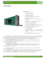
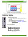
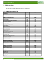
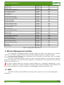
MCH User Manual Rev 1.8
MCH User Manual
Revision History:
Rev 1.8 01.12.2014
• Firmware version 2.10
Rev 1.7 10.07.2013
• Firmware version 2.4:added get_iua and sysreboot commands, and Late Boot warning for the fru command
Rev 1.6 24.06.2013
• Updated the Manual for the second generation of Hardware
Table of Contents
1 Description:.....................................................................................................................................................3
2 Front Panel and Connectivity.........................................................................................................................5
3 IPMB interface ..............................................................................................................................................6
3.1 Supported command list.........................................................................................................................6
4 Ethernet Management interface ....................................................................................................................7
4.1 WEB ......................................................................................................................................................7
4.1.1 Overview........................................................................................................................................8
4.1.2 Architecture....................................................................................................................................9
4.1.3 REST Commands...........................................................................................................................9
4.1.4 How it all works...........................................................................................................................13
4.2 Telnet....................................................................................................................................................15
4.3 RMCP..................................................................................................................................................15
4.4 DHCP....................................................................................................................................................15
4.5 TFTP.....................................................................................................................................................15
5 Serial interface ............................................................................................................................................16
5.1 Driver....................................................................................................................................................16
5.2 Terminal Program ..............................................................................................................................16
6 Redundant Operation ...................................................................................................................................16
7 Field Replaceable Unit (FRU) Management................................................................................................16
8 Command Line Interface (CLI) ...................................................................................................................18
8.1 Log-in ...................................................................................................................................................18
8.2 Syntax directory....................................................................................................................................18
8.2.1 activate command .........................................................................................................................18
8.2.2 bpppc command ...........................................................................................................................19
8.2.3 carrieraddr command ....................................................................................................................19
8.2.4 channels command .......................................................................................................................20
8.2.5 clock command ............................................................................................................................20
8.2.6 cu command .................................................................................................................................21
8.2.7 date command ..............................................................................................................................21
8.2.8 deactivate command .....................................................................................................................21
8.2.9 define command ..........................................................................................................................22
8.2.10 devices command .......................................................................................................................22
8.2.11 ekey command ............................................................................................................................23
8.2.12 fru command ..............................................................................................................................23
8.2.13 frubuffer command .....................................................................................................................24
8.2.14 fruinfo command ........................................................................................................................24
8.2.15 gbe_status command ..................................................................................................................25
8.2.16 get_iua command .......................................................................................................................26
8.2.18 help command ............................................................................................................................26
8.2.19 info command .............................................................................................................................26
www.samwayelectronic.com
1/38
MCH User Manual Rev 1.8
8.2.20 lanconfig - command ..................................................................................................................26
8.2.21 links command ...........................................................................................................................28
8.2.22 logout command .........................................................................................................................28
8.2.23 passw command .........................................................................................................................28
8.2.24 pcie command ............................................................................................................................29
8.2.25 reboot command .........................................................................................................................30
8.2.26 reset command.............................................................................................................................30
8.2.27 restore command ........................................................................................................................30
8.2.28 saveenv command ......................................................................................................................30
8.2.29 sel command ...............................................................................................................................30
8.2.30 scispeed command ......................................................................................................................31
8.2.31 sdr command ..............................................................................................................................31
8.2.32 sendipmb command ....................................................................................................................32
8.2.33 sensor command .........................................................................................................................32
8.2.34 sysreboot command ...................................................................................................................33
8.2.35 tftp command ..............................................................................................................................33
8.2.36 time command ............................................................................................................................33
8.2.37 turn command .............................................................................................................................34
8.2.38 uptime command ........................................................................................................................34
8.2.39 version command .......................................................................................................................34
8.2.40 xmodem command .....................................................................................................................34
9 Updating the Firmware.................................................................................................................................36
9.1 Local Firmware Update........................................................................................................................36
10 Restore to factory defaults .........................................................................................................................39
Illustration Index
Illustration 1: Samway MCH..............................................................................................................................3
Illustration 2: Tongue 1: Base Board Block Diagram.........................................................................................4
Illustration 3: Tongue 2: Clock Distribution Block Diagram.............................................................................4
Illustration 4: Tongue 3: PCIe Gen 3 Switch Block Diagram............................................................................5
Illustration 5: Front Panel...................................................................................................................................5
Illustration 6: Example Web page for a uTCA system......................................................................................8
Illustration 7: Representation of Web Page operation......................................................................................14
Illustration 8: FRU Management Diagram.......................................................................................................17
Illustration 9: Change CLI Baud Rate using scispeed command.....................................................................36
Illustration 10: New Terminal Settings.............................................................................................................36
Illustration 11: Local Firmware Update example.............................................................................................37
Illustration 12: TeraTerm xmodem send transfer.............................................................................................38
Illustration 13: Firmware Update example.......................................................................................................38
Index of Tables
Table 1: MCH LEDs...........................................................................................................................................5
Table 2: Supported Commands List....................................................................................................................7
Table 3: LAN addresses selection table............................................................................................................27
www.samwayelectronic.com
2/38
MCH User Manual Rev 1.8
1 Description:
Key Features:
•
•
•
•
•
•
Illustration 1: Samway MCH
•
•
•
•
•
•
•
•
•
Compliant to IPMI 1.5.
Compliant to MCTA.0:
Compliant to MCTA.4:
Compliant to HPM.1 firmware upgrade
Redundant Operation
Support for up to 12 AMCs,12 uRTMs 2 CUs
and 4 PMs
On-board Layer 2 unmanaged GbE Switch
PCIe Gen 3 12 ports Switch
2 Front panel GbE uplink ports
Front panel 10/100Mbps port for management
Front panel USB connector for debug
On-board shelf manager
Own IPMI software
Firmware upgrade via IPMI commands
(HPM.1), debug interface or TFTP remote
transfer
HTTP, DHCP, RMCP, and Telnet support
The MicroTCA Carrier Hub(MCH) is the heart of any MicroTCA System. It's main functions include
IPMI controlled power management, Electronic keying, Hot-swap of Advanced Mezzanine Cards (AMC),
Micro Rear Transition Modules (uRTM), Cooling Units (CU) and Power Modules (PM).
Samway's MCH supports up to 12 AMCs, 12 uRTMs , 2 CUs and 4 PMs, and is compliant to
MicroTCA specifications MCTA.0, MTCA.1 , MCTA.4.
Firmware upgrade is easily accomplished using the on-board debug interface, IPMI commands
(HPM.1 ) or remote access: TFTP.
MCH Redundancy is supported.
The MCH has been thoroughly tested at the Interoperability Workshops organized by PICMG.
The firmware uses a Samway Proprietary IPMI library and thus can be easily customized for
nonstandard MicroTCA solutions.
The product architecture is highly flexible and allows mezzanine add-ons: Clock Distribution
Module and PCIe Module.
The starting point of the configuration is the base board that provides the mandatory carrier manager
and an unmanaged Layer 2 Gigabit Ethernet switch for Fabric A connectivity. The switch connects to all
twelve ports of Fabric A using SERDES links and also to the two front panel up-link ports.
www.samwayelectronic.com
3/38
MCH User Manual Rev 1.8
Illustration 2: Tongue 1: Base Board Block Diagram
The Clock Distribution Mezzanine supports CLK3 for PCIe Fabric Clock. The PCIe clock is
distributed to all 12 AMCs and can be either a fixed frequency 100 MHz signal or a Spread Spectrum Clock
(SSC). The fabric clock distribution circuit is compliant to the timing requirements of PCIe Gen 3 clocks.
Illustration 3: Tongue 2: Clock Distribution Block Diagram
Upon request a more complex Clock Distribution Module can be developed, specially tailor to fit
either the standard Telecom Clock 1 and Clock 2 requirements or custom, user defined ones.
The PCI Express Mezzanine provides a nonblocking PCI Express Gen3 switching architecture that
supports up to 12 AMCs and flexible lane configuration of x1,x2,x4,x8 or even x16.
Up to 6 independent Virtual Switches that can split the PCIe domain into separate clusters can be
defined. The module operates using the PCIe fabric clock generated by the Clock Mezzanine module.
www.samwayelectronic.com
4/38
MCH User Manual Rev 1.8
Illustration 4: Tongue 3: PCIe Gen 3 Switch Block Diagram
Each virtual switch configuration is highly flexible and each Virtual Switch has its own PCIe domain
with dedicated upstream and downstream ports.
2 Front Panel and Connectivity
The MCH has 4 Front panel connectors:
•
2 x GbE Uplinks (GbE1,GbE2)– RJ45 connectors directly linked with the 16
ports GbE Switch. The switch provides switching functionality for system
Fabric A(1GbE).
•
Mgmt – RJ45 connector for 10/100 Ethernet management interface.
•
USB – USB mini B connector for the Serial interface . It provides access to
the on board CLI (command line interface)
The Samway-MCH is also equipped with the MicroTCA Hot-swap Handle
and the LEDs defined in MicroTCA .
Illustration 5:
Front Panel
Name
Color
Description
Blue Led
Blue
Hot swap led
Led 1
Red
Status Led:
off – Status ok
Red – error present
Led 2
Green
On – PP is present
Table 1: MCH LEDs
www.samwayelectronic.com
5/38
MCH User Manual Rev 1.8
3 IPMB interface
The MCH was developed based on the IPMI v1.5 specification.
3.1 Supported command list
IPM Device “Global”
Commands
NetFn
CMD
Get Device ID
App
01h
Get Self Test Results
App
04h
NetFn
CMD
Send Message
App
34h
Get Channel Authentication Capabilities
App
38h
Get Session Challenge
App
39h
Activate Session
App
3Ah
Set Session Privilege Level
App
3Bh
Close Session
App
3Ch
Event Commands
NetFn
CMD
Set Event Receiver
S/E
00h
Get Event Receiver
S/E
01h
Platform Event
S/E
02h
NetFn
CMD
Get Device SDR Info
S/E
20h
Get Device SDR
S/E
21h
Reserve Device SDR Repository
S/E
22h
Set Sensor Threshold
S/E
26h
Get Sensor Threshold
S/E
27h
Get Sensor Reading
S/E
2Dh
NetFn
CMD
Get FRU Inventory Area Info
Storage
10h
Read FRU Data
Storage
11h
Write FRU Data
Storage
12h
SDR Device Commands
NetFn
CMD
Get SDR Repository Info
Storage
20h
Reserve SDR Repository
Storage
22h
Get SDR
Storage
23h
NetFn
CMD
Get SEL Info
Storage
40h
Reserve SEL
Storage
42h
Get SEL Entry
Storage
43h
Clear SEL
Storage
47h
BMC Device and Messaging
Commands
Sensor Device Commands
FRU Device Commands
SEL Device Commands
www.samwayelectronic.com
6/38
MCH User Manual Rev 1.8
Get SEL Time
Storage
48h
Set SEL Time
Storage
49h
AdvancedTCA Commands
NetFn
CMD
Get PICMG Properties
PICMG
00h
Get Address Info
PICMG
01h
FRU Control
PICMG
04h
Get FRU LED Properties
PICMG
05h
Get LED Color Capabilities
PICMG
06h
Set FRU LED State
PICMG
07h
Get FRU LED State
PICMG
08h
Set FRU Activation Policy
PICMG
0Ah
Get FRU Activation Policy
PICMG
0Bh
Set FRU Activation
PICMG
0Ch
Set Power Level
PICMG
11h
Get Fan Speed Properties
PICMG
14h
Set Fan Level
PICMG
15h
Get Fan Level
PICMG
16h
AdvancedMC Commands
NetFn
CMD
Set AMC Port State
PICMG
19h
MicroTCA Commands
NetFn
CMD
Power Channel Control
PICMG
24h
Get Power Channel Status
PICMG
25h
PM Reset
PICMG
26h
PM Heartbeat
PICMG
28h
Table 2: Supported Commands List
4 Ethernet Management interface
The integrated 10/100Mbps Ethernet interface allows the MCH to be linked to any existing
network. The interface supports DHCP, TFTP, HTTP and TELNET protocols via TCP/IP and UDP.
The user has full access to the commands of the Command Line Interface (CLI) via TELNET,
allowing remote control of the MCH.
The use of standard protocols avoids the need for special software or drivers and so achieves
platform-independence. The TCP/IP protocol supports 10 simultaneous connections and the maximum
packet size is limited to 1k.
The factory default setting for the MCH is DHCP enabled so it negotiates automatically all the
necessary addresses. If a fixed IP address is desired, DHCP must be disabled and the address has
to be set manually. For all these operations the lanconfig command needs to be used.
4.1 WEB
The MCH includes a built in WEB server that provides a simple way to access the management
information.
www.samwayelectronic.com
7/38
MCH User Manual Rev 1.8
4.1.1 Overview
The WEB page can be designed as a graphical representation of the System Platform, thus providing
a very intuitive way of obtaining system / board information.(The illustration bellow exemplifies the web
page for a 12 slot system) . The available information includes:
• Board / Carrier /Shelf Field Replaceable Unit (FRU) information file (Manufacturer's Name, Part
number, Serial Number, Board Connectivity Records)
• Sensors information: value, name,measuring unit, status,threshold and hysteresis values
• System Event Log (SEL) : sensor events
• MCH attributes: MAC address, Serial number, Firmware version
Illustration 6: Example Web page for a uTCA system
The default Layout for the Web Page is composed of several areas:
1. Title: user defined
2. Logo: user defined
3. Dynamic System Platform Representation:: The images are populated or removed depending on the
hot-swap state of the boards. Both system platform and boards are treated as objects and can be
selected using a mouse click. The information in panes 4. FRU info and 5. Sensor info is changed
depending on the selected object.
www.samwayelectronic.com
8/38
MCH User Manual Rev 1.8
4. FRU info: displays the FRU information for the selected object( board or system platform)
5. Sensor info: displays the values, names and status for all the sensors of the selected object. All the
sensors are considered objects and can be selected using a mouse click.
6. System Event Log (SEL): displays all the sensor events received by the MCH starting from the
moment the Web page has been loaded.
7. Info Area: displays more details for the selected sensor (threshold and hysteresis values) or, if no
sensor is selected, displays MCH attributes: MAC address, Serial number, Firmware version.
8. Uptime : displays the amount of time the MCH has been operational. It is reset at each MCH restart.
4.1.2 Architecture
The Web Server uses a Representational State Transfer (REST) based architecture and Extensible
Markup Language (XML) files.
REST is an architectural style that abstracts the architectural elements within a distributed
hypermedia system. REST ignores the details of component implementation and protocol syntax in order to
focus on the roles of components, the constraints upon their interaction with other components, and their
interpretation of significant data elements. REST has emerged as a predominant web API design model.
XML is a markup language that defines a set of rules for encoding documents in a format that is both
human-readable and machine-readable. The design goals of XML emphasize simplicity,generality, and
usability over the Internet.
The MCH WEB page is composed of:
• objects : board and system images; sensors
• information display areas
When an object is selected by a mouse click, the web browser requests predefined XML files using
predefined commands. The information contained by the XML files returned by the MCH is parsed in the
information display windows.
The XML files could also be requested by an application software in case a custom managing
solution is required. The format of the XML files is described in the following chapter.
4.1.3 REST Commands
“/settings”
For this request the MCH returns an XML file containing the following tags:
•
•
•
•
•
<mac_addr>
<serial_no>
<host_name>
<firmware> : firmware version
<uptime> : the amount of time the MCH has been operational
• <H>: hours
• <M>: minutes
• <S>: seconds
www.samwayelectronic.com
9/38
MCH User Manual Rev 1.8
Request: GET /settings
IP Address/settings (ex: 192.168.16.1/settings)
Response:
<?xml version=”1.0”?>
<settings>
<mac_addr>0:80:194:242:80:0</mac_addr>
<serial_no>0000000000</serial_no>
<host_name>MCH_2013</host_name>
<firmware>1.6</firmware>
<uptime>
<H>0</H>
<M>31</M>
<S>21</S>
</uptime>
</settings>
“/frustatus”
For this request the MCH returns an XML file that contains the following tags:
• <boot_cnt>: boot index. The index is incremented at each MCH start-up.
• <sel_cnt>: System Event Log (SEL) index. The index is incremented when an event is added to the
SEL. This field is used to detect if new events have occurred.
• <fru_list>: a list with all the modules(FRUs) present in the system(including the MCH)
• <fru_addr>: the IPMB address of the module
• <fru_id>: active FRU ID. The Module Management Controller (MMC) is always represented by
FRU ID 0 and is always present for active modules. Additional FRU IDs can also be active.
Request: GET /frustatus
IP Address/frustatus (ex: 192.168.16.1/frustatus)
Response:
<?xml version=”1.0”?>
<fru_status>
<boot_cnt>315</boot_cnt>
<sel_cnt>9791</sel_cnt>
<fru_list>
<fru_addr addr="0x00">
<fru_id>0</fru_id>
<fru_addr addr="0x82">
<fru_id>0</fru_id>
</fru_addr>
<fru_addr addr="0x84">
<fru_id>0</fru_id>
</fru_addr>
<fru_addr addr="0x86">
<fru_id>0</fru_id>
</fru_addr>
<fru_addr addr="0x10">
<fru_id>0</fru_id>
</fru_addr>
</fru_list>
</fru_status>
“/sel/start_index/end_index”
This command retrieves multiple SEL event records. The command use two indexes (start,end) to
define the desired number of records. The MCH returns an XML file that contains all the event records that
www.samwayelectronic.com
10/38
MCH User Manual Rev 1.8
have an index between the start index and the end index. The XML file uses the following tags:
• <rec id> : the index of the current record
• <tmp> : the time when the event was triggered
• <addr>: address of the card that launched the event
• <lun>: the LUN on which the sensor resides
• <no>: sensor number
• <name>: sensor name
• <type>: code representing the sensor type
• <sta>: sensor state, available only for discrete sensors
• <ev_type>: threshold that triggered the event for threshold sensors: UNR (upper non-recoverable),
UC(upper critical), UNC(upper non-critical), LNC (lower non-critical), LC(lower critical),
LNR(lower non-recoverable)
• <ev_dir> Asserted, DeAsserted
• <val>: sensor value
• <thr>: threshold value
Request: GET /sel/start_index/end_index
IP Address/sel/start_index/end_index (ex: 192.168.16.1/sel/1/2)
Response:
<?xml version=”1.0”?>
<sel>
<rec id="1">
<tmp>1325376000</tmp>
<addr>0x72</addr>
<lun>0</lun>
<no>97</no>
<name>MCH Power ON</name>
<type>192</type>
<sta>0</sta>
</rec>
<rec id="2">
<tmp>1325376000</tmp>
<addr>0x72</addr>
<lun>0</lun>
<no>2</no>
<name>V0</name>
<type>2</type>
<ev_type>LNC</ev_type>
<ev_dir>Asserted</ev_dir>
<val>0.00</val>
<thr>2.86</thr>
</rec>
</sel>
“/fruinfo/FRU_Address/FRU_Id”
This command retrieves a text file containing the FRU information for the desired FRU Id on the
specified card. The command uses two parameters:
• FRU_Address: the IPMB address of the card(hexadecimal value)
• FRU_Id: used to distinguish between multiple FRUs located on the same card. The FRU Id for the
Module Management Controller (MMC),(the card itself) is 00.
Request: GET /fruinfo/FRU_Address/FRU_Id
IP Address/fruinfo/FRU_Address/FRU_Id(ex: 192.168.16.1/fruinfo/0x82/0)
www.samwayelectronic.com
11/38
MCH User Manual Rev 1.8
Response( text file):
INTERNAL USE AREA 0x01 0x02 0x03 0x04 0x05 0x06 0x07 0x08 0x09 0x0A 0x0B 0x0C
0x0D 0x0E 0x0F 0x00 RODUCT INFO AREA Manufacturer Name: SAMWAY Product Name:
Test Board MULTIRECORD AREA Module Current Requirement Amp=1.0
“/sensor/FRU_Address/FRU_Id”
This command retrieves all the sensor associated to a FRU Id of a card. The command uses two parameters:
• FRU_Address: the IPMB address of the card(hexadecimal value)
• FRU_Id: used to distinguish between multiple FRUs located on the same card. The FRU Id for the
Module Management Controller (MMC),(the card itself) is 00.
If this parameter is missing the MCH will return the sensors associated to FRU Id 0
The MCH responds to this request using an XML file that contains the following tags:
<name>:sensor name
<value>:sensor value
<unit>:sensors unit of measurement
<state>:sensor state (lnr, lc, lnc, unc, uc, unr)
Request: GET /sensor/FRU_Address/FRU_Id
IP Address/sensor/FRU_Address/FRU_Id(ex: 192.168.16.1/sensor/0x82)
Response:
<?xml version=”1.0”?>
<sensor_list>
<sensor no="1">
<name>Hot Swap</name>
<value>Handle Open </value>
</sensor>
<sensor no="2">
<name>V0</name>
<value>0.00</value>
<unit>V</unit>
<state>lnr</state>
</sensor>
</sensor_list>
“/sdr/FRU_Address/sensor_No”
This command retrieves additional information for a specific sensor on the desired card. The
command uses two parameters:
• FRU_Address: the IPMB address of the card(hexadecimal value)
• sensor_No: sensor number for the desired sensor
The MCH responds to this request using an XML file that contains the following tags:
•
•
•
•
•
•
•
•
•
•
<name>
<entity_id> : entity id for the sensor's owner
<entity_instance> :entity instance for the sensor's owner
<unr>: upper non-recoverable threshold value, if the unr threshold is enabled
<uc>: upper critical threshold value, if the uc threshold is enabled
<unc>: upper non-critical threshold value, if the unc threshold is enabled
<lnc>: lower non-critical threshold value, if the lnc threshold is enabled
<lc>: lower critical threshold value, if the lc threshold is enabled
<lnr>: lower non-recoverable threshold value, if the lnr threshold is enabled
<hyst_pos>: positive going hysteresis value
www.samwayelectronic.com
12/38
MCH User Manual Rev 1.8
• <hyst_neg>: negative going hysteresis value
• <nominal_reading>
• <normal_maximum>
• <normal_minimum>
• <maximum_reading>
• <minimum_reading>
Request: GET /sdr/FRU_Address/sensor_No
IP Address /sdr/FRU_Address/sensor_No(ex: 192.168.16.1/sensor/0x10/5)
Response:
<?xml version=”1.0”?>
<sensor no="5">
<name>V3</name>
<entity_id>0x01</entity_id>
<entity_instance>0x61</entity_instance>
<uc>-11.34</uc>
<lc>-12.64</lc>
<hyst_pos>0.07</hyst_pos>
<hyst_neg>0.07</hyst_neg>
<nominal_reading>-14.00</nominal_reading>
<normal_maximum>-14.00</normal_maximum>
<normal_minimum>-14.00</normal_minimum>
<maximum_reading>2.58</maximum_reading>
<minimum_reading> -14.00</minimum_reading>
</sensor>
“/picture/FRU_Address”
This command retrieves the pictures for the boards and system platform.
• FRU_Address: the IPMB address of the card(hexadecimal value). For the picture of the System
platform the request uses FRU_Address = 0.
Request: GET /picture/FRU_Address
IP Address /picture/FRU_Address(192.168.16.1/picture/0x80; 192.168.16.1/picture/0)
Response: picture file
4.1.4 How it all works
The web page has 2 operational states: Initialization and Normal Operation. A functional diagram of
the default web page operation can be found bellow.
At start-up, and each time it is re-initialized, the web page is empty. The Web page requests and
saves the MCH settings (GET/settings): MAC Address, Serial Number, Firmware Version,Uptime. The page
also saves some parameters from the response of the frustatus request: Boot count, SEL count.
Next, the web page request information for the system platform( FRU 0): picture, FRU info, sensors.
(GET/picture/0, GET/fruinfo/0/0, GET/sensor/0/0). Once the information is received, the web page
displays it.
After the system platform is initialized the init phase ends. By default all boards are considered
absent during this phase.
The normal operation phase of the web page is split in two processes:
• A periodical process that check to see if new boards have been inserted, or if boards have been
removed
• A mouse click listener that changes the active object
www.samwayelectronic.com
13/38
MCH User Manual Rev 1.8
Illustration 7: Representation of Web Page operation
The periodic process issues a GET/frustatus request at every 3 seconds. By comparing the FRU list
in the response and the FRUs loaded, the page determines if boards have been inserted or removed. For all
the new boards the web page sends a GET/picture/FRU_Address request and loads the received picture.
For all the boards that have been removed, the web page also removes the picture.
Using the response for the frustatus request the web page also checks if new SEL events have
occurred. If the SEL count from the response is different from the one saved by the page, a
GET/sel/old_count+1/new_count request is sent. Using the response the web page displays all the new SEL
events.
The frustatus request is also used to detect restarts of the MCH. If the Boot count in the response is
different than the saved one, the WEB page is restarted: all pictures are removed and all the internal
www.samwayelectronic.com
14/38
MCH User Manual Rev 1.8
variables are reinitialized.
The WEB page uses a mouse click listener to determine if the current selected object has been
changed. The WEB page uses two types of objects:
•
FRU images
•
FRU sensors
At each mouse click the WEB page determines if the active object has been changed.
If the active FRU image object has been changed, the WEB page request the FRU info and sensors
for the new active object: GET/fruinfo/FRU_Address/0, GET/sensor/FRU_Address/0. Using the
responses of the requests, the web page updates the information visible in the FRU Info and Sensor Info
panels. By default, at start-up, the active image object is the system platform (FRU 0).
If the active sensor object has been changed, the WEB page request the detailed information or the
new active sensor: GET/sdr/FRU_Address/Sensor_No. Using the response for the sdr request, the WEB
page updates the information in the Info Area panel. By default, at start-up no sensor object is selected and
the Info are panel displays MCH parameters: MAC address, Serial No., Firmware version.
After the first sensor object becomes active, the Info Area panel will display sensor information. To
return to displaying MCH parameters, a click on the system platform image is necessary.
4.2 Telnet
The Telnet interface can be used to gain access to the Command Line Interface (CLI) .The CLI is
accessible if the operator is logged on as “user” or “admin” profile.
Terminal settings:
• Local echo: off
• Local line editing: off
• Backspace key: Control-H
For the default access settings refer to the CLI chapter.
4.3 RMCP
The MCH supports Remote Management Control Protocol (RMCP). The RMCP connections requires
authentication. The supported authentication protocol is MD5. Two user names are accepted for RMCP
connections: “user” – with “User” privilege level and “admin” with “Administrator” privilege level. The
user names and privilege levels are fixed, they cannot be changed through IPMI commands. The password
used are the same passwords configured for the CLI. The default passwords are: “USER” – for “user” profile
and “ADMIN” - for admin profile.
4.4 DHCP
The MCH supports Dynamic Host Configuration Protocol (DHCP). With DHCP, the MCH request IP
addresses and networking parameters automatically from a DHCP server, reducing the need for a user to
configure these settings manually.
4.5 TFTP
The MCH supports Trivial File Transfer Protocol (TFTP) for updating it's firmware or the on-board
web page. TFTP is a simple, lock-step,file transfer protocol which allows a client to get a file from a remote
www.samwayelectronic.com
15/38
MCH User Manual Rev 1.8
host. TFTP allows remote firmware/ web page update and also significantly reduces the upload time when
compared to the RS232 xmodem alternative.
5 Serial interface
The MCH provides a serial interface over which the commands of the Command Line Interface
(CLI) can be sent.
The CLI is available via the front panel USB mini B connector.
5.1 Driver
The Samway-MCH uses the FT232R chip for converting the serial Command Line Interface to USB
signals.
For successfully connecting a PC to the MCH, a Virtual COM port (VCP) driver is required. Usually
the appropriate driver is automatically detected and installed by the operating system.
In case the operating system fails to install the correct driver, you can download the latest driver for
FT232R from here, and follow the instructions of the installation guides.
5.2 Terminal Program
Once the driver has been successfully installed you can connect to the MCH using any terminal
program.
On Windows systems, we recommend the use of “TeraTerm” or “Hyperterminal” as terminal
programs.
Terminal settings:
• 19200 bits per second (default baud rate);this baud rate can be changed using “scispeed” CLI
command
• data bits: 8
• parity: none
• stop bit: 1
In addition, the “xmodem” CLI command can be used for file transfer.
6 Redundant Operation
The MCH supports redundant operation. At each start-up primary and redundant status is negotiated
by the two MCHs. After the negotiation is done the primary MCH will start to actively manage the Chassis.
The redundant MCH will remain inactive until a switch-over changes it's role to primary. The switchover can be triggered by a CLI command, a reboot, hot-swapping, or a failure of the primary MCH.
7 Field Replaceable Unit (FRU) Management
The MCH manages and controls all FRUs residing in a MicroTCA Carrier (AdvacendMCs, Power
Modules, Cooling Units, OEM Modules) through a set of signals controlled by the PMs and it's IPMB
interfaces.
The communication between the MCH and the other FRUs takes place over the IPMB-L and IPMB-0
interfaces.
www.samwayelectronic.com
16/38
MCH User Manual Rev 1.8
The MCH uses I2C buffers to connect to IPMB-A,IPMB-B and all twelve IPMB-L buses, thus being
able to disconnect a faulty AMC without loosing communication with the other ones.
Regardless of the FRU type, the way it is managed by the MCH is similar and can be described by
the following diagram:
Illustration 8: FRU Management Diagram
The MCH checks operating parameters and decides if it needs to change a FRU's state:
•
Presence: for AMCs and CUs, the presence is detected by the PM. The PM precence is detected by
issuing a “Get Device Id” request and waiting for the response.
•
Activation Criteria Met: Hot swap handle closed or MCH CLI activate command
•
De-activation Criteria Met: Hot swap handle open or MCH CLI deactivate command
•
Communication Failure: a number of consecutive IPMB request fail to receive a response
The management diagram is comprised of 5 distinct states:
•
Discovery: FRU Information and Sensor data are read
•
Activation: Payload Power is enabled and Ekey-ing is done
•
Normal Operation: FRU IPMB operational status is checked by issuing an IPMB request from time
to time. If a number of consecutive messages fail to receive an answer, the state is changed to
Communication Lost.
•
De-Activation: Payload Power is disabled
www.samwayelectronic.com
17/38
MCH User Manual Rev 1.8
•
Communication Lost: IPMB communication status is re-checked from time to time by issuing an
IPMB request. If Communication is restore the FRU exists the current state and the process is
restarted.
8 Command Line Interface (CLI)
The Command Line Interface ( short-form: CLI ) is available via the USB interface. The user can
read or newly configure and save system parameters via the CLI. Access is divided into 2 profiles and is
password-protected.
“user” profile:
System parameters can only be read in this profile – the exception to this write-protect is the
lanconfig command for setting the IP, subnet and gateway addresses.
“admin” profile:
Full access to all system parameters. All available CLI commands can be executed. To avoid
possible damage or malfunctions, the access data for this profile must only be known to trained
personnel with appropriate knowledge and competence relating to the system in which the MCH is
used!
The profiles can be changed using logout.
8.1 Log-in
As soon as you have established a connection, you will be prompted to login.
Default access settings:
login: user
password: USER
login: admin
password: ADMIN
The passwords can be changed using “passw”.
8.2 Syntax directory
Syntax Rules:
•
syntax is case sensitive
•
parameters in [..] are optional
•
parameters in < .. > are numbers
8.2.1 activate command
Syntax: activate amc | pm | cu | mcmc <site>
amc_site: 1..12
pm_site: 1..4
cu_site: 1..2
www.samwayelectronic.com
18/38
MCH User Manual Rev 1.8
mcmc_site: 1..2
Description: activates the desired FRU.
Example:
%>activate amc 1
Done!
8.2.2 bpppc command
Syntax: bpppc
Description: back plane point to point connectivity: Displays a summary of the backplane AMCs
connectivity. The Columns represent all the AMCs in the system and the rows represent all the ports of
those FRUs.
Example:
%>bpppc
----------------------Backplane point to point connectivity---------------*Legend : 3M1A = Port 3 MCH 1 Fabric A
5A10 = Port 5 AMC 10
AMC
1
2
3
4
5
6
7
8
9
10
11
12
--------------------------------------------------------------------------P0 0M1A 1M1A 2M1A 3M1A 4M1A
P1
P2 2A3
2A1
3A3
3A4
P3
2A4
2A5
P4 4A3
4A4
4A1
4A2
4M1D
P5 5A3
5A4
5A1
5A2
4M1E
P6 6A3
6A4
6A1
6A2
4M1F
P7 7A3
7A4
7A1
7A2
4M1G
P8
P9
P10
P11
P12
P13
P14
P15
P16
P17
P18
P19
P20
-
The highlighted info translates into : AMC 3 port 2 is linked to AMC 1 port 2.
8.2.3 carrieraddr command
Syntax: carrieraddr
Description: Displays the IPMB address of the Carrier.
Example:
%>carrieraddr
Carrier Address =0x82
www.samwayelectronic.com
19/38
MCH User Manual Rev 1.8
8.2.4 channels command
Syntax: channels
Description: Displays information regarding the power status of each FRU in the system: PS1, MP, EN, PP.
The command also displays information regarding the PMs in the system: PM's status(redundant,primary,not
used), amount of used current, amount of available current.
The info is structured using a table. The lines represent the channels, and each of the columns has a
different meaning:
PS1 : present
MP : management power
EN : enable
PP : payload power
Legend: “y” - asserted , “-” -not asserted.
Example:
%>channels
____________________________________________________________________
Primary PM
Redundant PM
Current
Channel Device
No. PS1 MP EN PP
No. PS1 MP EN PP
AMPs
____________________________________________________________________
1
MCMC 1
1
y y y y
2
y y y y
3.0
3
CU 1
1
y y y y
2
y y y y
2.0
5
AMC 1
- - - - - - 6
AMC 2
1
y y y y
2
y y y y
5.0
7
AMC 3
- - - - - - 8
AMC 4
- - - - - - 9
AMC 5
- - - - - - 10
AMC 6
- - - - - - _______________________________________________________________________________________
Current[AMP]
PM
Status
Capability
BP Override
Used
no.
PM1
PM2
PM3
PM4
______________________________________________________________________________________
1 Primary
25.0
50.0
10.0
2 Redundant
25.0
50.0
10.0
In this case channel 2 (CU1), is present (PS1 is asserted), receives management power, is enabled and
receives payload power( MP1,EN and PP asserted); has a primary PM and a redundant PM assigned(PM1
-primary, PM2 -redundant), and has a current requirement of 2 Amps.
8.2.5 clock command
Syntax: clock [ pcie en|di <amc_site> | all ]
Description: Displays information regarding the clocking of the system. The command can enable/disable
the clocks.
amc_site= 1..12
Example 1:
%>clock
--------------------------AMC
Clock Status
No. PCIe
--------------------------1
ON
2
ON
3
OFF
4
OFF
www.samwayelectronic.com
20/38
MCH User Manual Rev 1.8
5
6
7
8
9
10
11
12
OFF
OFF
ON
ON
ON
OFF
OFF
OFF
Example 2:
%>clock pcie en 3
Done!
8.2.6 cu command
Syntax: cu [ <cu_site> (fanlevel shutdown | <level_value>) | (local_control on|off) [rear] ]
cu_site: 1..2
level_value:1..15
Description: Displays or configure the Cooling Units operation. The command displays minimum and
maximum fan levels,the normal operating fan level and the current fan level. The command supports front
and rear fans according to MTCA.4.
Example1: get cu status
%>cu
---------------------Cooling Status---------------------Local Control
Fan Levels
Device Instance
State
Level
Override Normal Min Max
--------------------------------------------------------CU 1
Off
10
3
1
15
Example2: set rear fan level in a MTCA.4 chassis
%>cu 1 fanlevel 10 rear
Set fan level req sent!
Command acknowledged!
8.2.7 date command
Syntax: date [dd.mm.yyyy]
Description: Displays or set the RTC Date. The command is available only when the RTC is enabled.
(check out the define command)
Example1: get date
%>date
Date [dd.mm.yyyy] = 10.12.2014
8.2.8 deactivate command
Syntax: deactivate amc | pm | cu | mcmc <site>
amc_site: 1..12
pm_site: 1..4
cu_site: 1..2
mcmc_site: 1..2
Description: Deactivates the desired FRU.
Example:
%>deactivate amc 5
Done!
www.samwayelectronic.com
21/38
MCH User Manual Rev 1.8
8.2.9 define command
Syntax: define (quiesced timeout [<t_value>] ) |
(startup_power_policy [ <sp_value>]) |
(unmanaged_channels [<hex_val> ]) |
(rtc [en | di ]) |
(upstream_delay [custom | default])
t_value: 0..655 (seconds)
sp_value: 0..1
hex_value: hexadecimal value
Description: Displays or configures various parameters:
• quiesced timeout: After sending a FRU control (Quiesce) command to a FRU, the MCH waits for the
FRU to enter the Quiesced state. After the quiesced timeout expires, the MCH proceeds to disabling
the Payload Power for the FRU even if the Quiesced state was not reached. The default timeout value
is 60 seconds.
• start-up_power_policy: this parameter defines the behavior for the MCH power up PM assign
process in case the channels that receive autonomous PP (MCH1, MCH2, CU1, CU2) are not
powered by the PM specified in the Carrier FRU File. The start-up PM will be changed for those
channels and there are 2 options for the switch:
◦ 0 – the autonomous channels that were not enabled by the Carrier FRU designated PM are
disabled and re-enabled on the required PM
◦ 1 – the autonomous channels that were not enabled by the Carrier FRU designated PM are not
disabled but they are moved to the same PM that will also provide power for the primary MCH.
• unmanaged_channels: this parameter defines a set of channels that will not be managed by the MCH.
This means that the MCH will not not control MP,EN# and PP signals assertion or deassertion for the
respective channel. The hex_val parameter is a hexadecimal representation of the power channels
with channel x being represented by (0x01 << (x -1)). The power signals for the unmanaged channels
are controlled using the turn command.
• RTC : enabled | disabled the real time clock
All parameters changed by this command will be active at the next power on, if the environment
changes are saved using the saveenv command.
Example1: set the quiesced timeout to 120 seconds
%>define quiesced timeout 120
Done! The new value will be active at the next startup if you saveenv!
Example2: change the start-up_power_policy
%>define startup_power_policy 1
Done! The new value will be active at the next startup if you saveenv!
Example3: define AMC 5 – channel 9 as unmanaged
%>define unmanaged_channels 0x0100
Done! The new value will be active at the next startup if you saveenv!
Unmanaged Channels: 0x0100
8.2.10 devices command
Syntax: devices
Description: Displays the string used by the web page to identify board pictures
www.samwayelectronic.com
22/38
MCH User Manual Rev 1.8
Example1:
%>devices
MCMC1 ID07010SMW02C111
PM4
ID07010P07-003
CU1
ID07010031-088
CU2
ID07010031-088
AMC1
ID03A9813
8.2.11 ekey command
Syntax: ekey
Description: Displays a summary of the E-Keying process.
Example:
%>ekey
Ekeying Summary
AMC
Ports
Partner
Ports
Type
--------------------------------------------------------------AMC2 0
MCH1 F-A 2
Ethernet 1000Base-BX
AMC2 1
MCH1 F-A 8
Ethernet 1000Base-BX
AMC2 2
AMC4
2
Storage SATA
AMC4 2
AMC2
2
Storage SATA
8.2.12 fru command
Syntax: fru
Description: Displays the active devices (PMs,AMCs and CUs) and their operational states. The command
also displays the FRU's name(if available).
For MCHs equipped with PCIe the command displays a warning for boards that have booted after the
CPU (PCIe upstream port) is operational. The Late Boot Warning is marked by a star in the Address
column.
Example 1:
%>fru
---------------- FRU Summary --------------------------------------Address FRU
Device State Prev Reason
Name
-------------------------------------------------------------------0x10
0x00 MCMC1
M4
M3 Normal Change
MCMC
0xA8
0x00 CU1
M4
M3 Normal Change
Cooling Unit
0xAA
0x00 CU2
M4
M3 Normal Change
Cooling Unit
0x72
0x00 AMC1
M4
M3 Normal Change
A2:AM4011
0x76
0x00 AMC3
M4
M3 Normal Change
AMC-S302-80G
0x80
0x00 AMC8
M4
M3 Normal Change
AMC Test Card
0xC8
0x00 PM4
M4
M3 Normal Change
PDM
Example 2: PCIe MCH with AMC8 booting late (booting after the upstream port has become
operational)
%>fru
---------------- FRU Summary --------------------------------------Address FRU
Device State Prev Reason
Name
-------------------------------------------------------------------0x10
0x00 MCMC1
M4
M3 Normal Change
MCMC
0xA8
0x00 CU1
M4
M3 Normal Change
Cooling Unit
0xAA
0x00 CU2
M4
M3 Normal Change
Cooling Unit
0x72
0x00 AMC1
M4
M3 Normal Change
A2:AM4011
*0x80
0x00 AMC8
M4
M3 Normal Change
AMC Test Card
0xC8
0x00 PM4
M4
M3 Normal Change
PDM
www.samwayelectronic.com
23/38
MCH User Manual Rev 1.8
8.2.13 frubuffer command
Syntax: frubuffer
Description: Displays the raw fru info for all the FRUs in the system. The FRUs are identified by their
IPMB address.
Example:
%>frubuffer
Device: 0xFD
FRU ID: 0x00
FRU file Length: 938
Buffer Length: 948
01 00 01 04 11 1C 00 CD 01 03 01 C7 30 33 37 2D
...............................................
Device: 0xFE
FRU ID: 0x00
FRU file Length: 318
Buffer Length: 328
01 00 01 04 11 1C 00 CD 01 03 01 C7 30 33 37 2D
...............................................
Device: 0xC2
FRU ID: 0x00
FRU file Length: 20
Buffer Length: 28
01 00 00 00 00 01 00 FE C0 82 07 54 63 5A 31 00
...............................................
Device: 0x10
FRU ID: 0x00
FRU file Length: 876
Buffer Length: 884
01 00 00 01 05 0A 00 EF 01 04 19 40 6B 81 C6 53
...............................................
Device: 0xA8
FRU ID: 0x00
FRU file Length: 19
Buffer Length: 28
01 00 00 00 00 01 00 FE C0 82 06 4B 6D 5A 31 00
...............................................
Device: Free Area
FRU ID: 0xFF
FRU file Length: 48748
Buffer Length: 48756
8.2.14 fruinfo command
Syntax: fruinfo (amc|cu|pm|mcmc site) | carrier | shelf | <IPMB Address>
Description: Parses the FRU Information File for the desired device
Example:
%>fruinfo amc 2
INTERNAL USE AREA
Internal Use Area missing
BOARD INFO AREA
Board Manufacturer: Generic Manufacturer
Board Product Name: AMC 1
Board Serial Number: 000999
Board Part Number:
A9876
PRODUCT INFO AREA
Manufacturer Name: Generic Manufacturer
www.samwayelectronic.com
24/38
MCH User Manual Rev 1.8
Product Name:
AMC test card
Model Number:
AMC7865
Product Version:
Rev. B
Product Serial Number: 000999
MULTIRECORD AREA
Module Current Requirement
Amp=3.0
AMC P-P Connectivity
AMC Record Type
ChID:0
ChID:1
Lane0:P0
Lane0:P4
Link:0
Link:1
Link:2
Link:3
Link:4
ChID:0
ChID:1
ChID:1
ChID:1
ChID:1
Lane1: Lane1:P5
Lane2: Lane2:P6
Lane3: Lane3:P7
L0
Eth 1000Base-BX
L0 L1 L2 L3 PCIe Gen2
L0
PCIe Gen2
L0 L1 L2 L3 PCIe Gen1
L0
PCIe Gen1
Asym.
Asym.
Asym.
Asym.
Asym.
Match
Match
Match
Match
Match
=
=
=
=
=
0
2
2
2
2
Gr.
Gr.
Gr.
Gr.
Gr.
Id
Id
Id
Id
Id
=
=
=
=
=
0
0
0
0
0
8.2.15 gbe_status command
Syntax: gbe_status
Description: displays the connection status and parameters for all the GbE links connected to the on-board
GbE switch.
Example:
%>gbe_status
--------------GbE Links Status--------------------------------Link-------State---------Type-------Speed-------Duplex-----AMC 1
Link Down
AMC 2
Link Up
SerDes
1 Gbs
Full
AMC 3
Link Down
AMC 4
Link Down
AMC 5
Link Down
AMC 6
Link Up
SerDes
1 Gbs
Full
AMC 7
Link Up
SerDes
1 Gbs
Full
AMC 8
Link Down
AMC 9
Link Down
AMC 10
Link Down
AMC 11
Link Down
AMC 12
Link Down
Uplink 1
Link Down
Uplink 2
Link Up
SGMII
100 Mbs
Full
8.2.16 get_iua command
Syntax: get_iua amc <site>
site:1..12
Description: reads the Internal Use Area of the FRU file for an AMC
Example:
%>get_iua amc 3
AMC 3 FRU File Internal Use Area
Area length:56 Bytes
0x01 0x07 0x03 0x04 0x05 0x06 0x07 0x08
www.samwayelectronic.com
25/38
MCH User Manual Rev 1.8
0x09
0xFF
0xFF
0xFF
0x11
0x11
0x0A
0xFF
0xFF
0xFF
0x11
0x11
0x0B
0xFF
0xFF
0xFF
0x11
0x11
0x0C
0xFF
0xFF
0xFF
0x11
0x11
0x0D
0xFF
0xFF
0xFF
0x11
0x11
0x0E
0xFF
0xFF
0xFF
0x11
0x11
0x0F
0xFF
0xFF
0xFF
0x11
0x11
0x00
0xFF
0xFF
0xFF
0x11
0x11
8.2.17
8.2.18 help command
Syntax: help [-v]
Description: Displays a list of all the available CLI commands. If the command is used with the verbose
parameter (-v),a short description and an example are displayed for each supported CLI command.
8.2.19 info command
Syntax: info amc|pm|cu|mcmc <site>
amc site = 1..12
pm site = 1..4
cu site = 1..2
mcmc site = 1..2
Description: Parses the information returned by the response for a Get Device ID request: Device
ID,Firmware version,IPMI version,Manufacturer ID,Product ID.
Example:
%>info amc 2
Name: AMC Test Card
Device ID: 0x01
Device provides SDRs
Device Revision: 1
Device Available: Normal Operation
Firmware Revision: 3.0
IPMI Version: 1.5
Additional Device Support:
IPMB Event Generator
FRU Inventory Device
Sensor Device
Manufacturer ID: 28688d = 07010h
Product ID: 0x0100
8.2.20 lanconfig - command
Syntax: lanconfig [dhcp [on|off]] | [local [on|off]] |
[savelocaltofru] | [settings]
|
[ip | mask | gateway [<address>]]
Description: Readout or setup for the network parameters.
• no parameter used– the command returns current IP, mask and gateway addresses of the LAN
interface
• settings – shows the configuration of the LAN interface: the state of all parameters and addresses
• savelocaltofru – saves the local addresses in the Carrier Manager IP Link record on the Backplane
Carrier FRU EEPROM.
• dhcp [on|off] – enables or disables the DHCP. The local mode has to be turned on in order to use
DHCP.
• local [on|off] – enables or disables the local LAN interface settings
www.samwayelectronic.com
26/38
MCH User Manual Rev 1.8
• ip | mask | gateway [address] – set or print the local addresses
Depending on the state of the local and dhcp lanconfig parameters one of the 3 LAN parameter sets is
used:
• addresses from the Carrier Manager IP Link FRU Record in the Carrier FRU Information File
• local addresses
• dhcp addresses
LAN addresses defined by
local
dhcp
Carrier Manager IP Link Record
off
off
Local addresses
on
off
DHCP
on
on
Table 3: LAN addresses selection table
At startup the MCH checks if the local configuration is on or off. If it is off, the LAN addresses are read
from the Carrier Manager IP Link FRU record. If this record is missing or the addresses are not specified
(value 0.0.0.0) the local set is used.
Depending on the dhcp parameter, the local address or the ones obtained using DHCP are used.
After a parameter is modified, the change must be saved with saveenv and the MCH has to be
restarted (reboot command) before the change becomes effective.
Example1: Readout of current LAN addresses
%>lanconfig
DHCP Configuration
IP=172.16.14.13
Mask=255.255.255.0
Gateway=172.16.14.201
Example2: Readout of all the lanconfig parameters
%>lanconfig settings
FRU Info IP=0.0.0.0
FRU Info Mask=0.0.0.0
FRU Info Gateway=0.0.0.0
DHCP =On
Local Configuration =On
Local IP=192.168.16.17
Local Mask=255.255.255.0
Local Gateway=172.21.35.211
Example3: Changing the local IP address
%>lanconfig ip 172.16.14.18
Local IP=172.16.14.18
Example4: Enabling the local LAN settings
%>lanconfig local on
LAN configured by local settings: on
8.2.21 links command
Syntax: links amc <site>
site : 1..12
www.samwayelectronic.com
27/38
MCH User Manual Rev 1.8
Description: Displays a list of all the links defined in the AMC Point to Point Records of the FRU
Information File of the desired AMC. For every link the command displays:
• the link type
• the ports it uses
• the link's grouping id field
• the link's asymmetric match field
• the links status: enabled,disabled,waiting enable,waiting disable
• partner
Example:
%>links amc 2
AMC 2
No--Link Type---------------Ports--------Gr.Id--As.Match-Status----Partner------------0 Ethernet 1000Base-BX
0
0x00
0x00
Enabled
MCH1 F-A 2
1 Ethernet 1000Base-BX
1
0x00
0x00
Enabled
MCH1 F-A 8
2 Storage SATA
2
0x00
0x02
Enabled
AMC4 2
3 Storage SATA
3
0x00
0x02
Disabled
4 PCI Express Gen1-SSC
4 5 6 7
0x00
0x02
Disabled
5 PCI Express Gen1
4 5 6 7
0x00
0x02
Disabled
6 PCI Express Gen1-SSC
4
0x00
0x02
Disabled
7 PCI Express Gen1
4
0x00
0x02
Disabled
In this example AMC 2 has 3 enabled links: two connected to the MCH fabric A port 2 and 8 and one
connected to AMC 4 port 2.
8.2.22 logout command
Syntax: logout
Description: Loggs out the current user.
Example:
%>logout
login:
8.2.23 passw command
Syntax: passw
Description: Changes the password for the current user
Examples:
%>passw
Enter Old password:****
Enter new password:****
Use saveenv command before reboot for the change to be successful!
8.2.24 pcie command
Syntax: pcie [ (upstream [vs<x>] [port <p_no>]) |
(timeout [<time_val>]) |
(vs<x> <port_list>) ]
vs<x>: vs0,vs1..vs5
p_no:0..11
time_val:1..255
www.samwayelectronic.com
28/38
MCH User Manual Rev 1.8
port_list: 0,1,2..11
Description: Displays the status of all PCIe links connected to the on-board switch.
Displays or changes the upstream port for any of the virtual switches.
Displays or changes the timeout for the start-up of the upstream ports.
Displays or changes the ports contained by any virtual switch.
Example 1: PCIe link status
%>pcie
------------------------------------------------------------------Virtual
PCIe Links Status
Link
Switch Port Type
State
Speed
Width
Clock
------------------------------------------------------------------PORT 0
VS0
Upstream
Link Up
Gen 1
x4
ON
PORT 1
VS0
Downstream
Link Up
Gen 1
x1
ON
PORT 2
VS1
Upstream
Link Down
OFF
PORT 3
VS1
Downstream
Link Down
OFF
PORT 4
VS2
Upstream
Link Up
Gen 3
x4
ON
PORT 5
VS2
Downstream
Link Up
Gen 3
x4
ON
PORT 6
VS3
Upstream
Link Down
OFF
PORT 7
VS3
Downstream
Link Down
OFF
PORT 8
VS3
Downstream
Link Down
OFF
PORT 9
VS3
Downstream
Link Down
OFF
PORT 10
VS3
Downstream
Link Up
Gen 3
x4
ON
PORT 11
VS3
Downstream
Link Down
OFF
Example 2: Set Port 4 as the upstream port for vs0 (by default all ports are in vs0)
%>pcie upstream port 4
Operation successful! To validate the change use saveenv!
The Upstream port change will be active at the next power on!
PCIe VS0 Upstream port: 4
Example 3: Set Port 6 as the upstream port for vs3(Port 6 belongs to vs3)
%>pcie upstream vs3 port 6
Operation successful! To validate the change use saveenv!
The Upstream port change will be active at the next power on!
PCIe VS3 Upstream port: 6
Example 4: assign ports 6,7,8,9,10,11 to vs3
%>pcie vs3 6 7 8 9 10 11
Operation successful! To validate the change use saveenv!
The Virtual Switch port change will be active at the next power on!
Example5: Set 30 seconds upstream port start-up up delay
%>pcie timeout 30
Operation successful! To validate the change use saveenv!
PCIe Upstream port bring-up timeout: 30 sec
8.2.25 reboot command
Syntax: reboot
Description: Restarts the MCH.
Examples:
%>reboot
Bootloader Version 1.7M
Press x to stop bootloader in: 0 Expired!
Running main program..ÿ
www.samwayelectronic.com
29/38
MCH User Manual Rev 1.8
8.2.26 reset command
Syntax: reset warm|cold amc|cu <site>
amc_site:1..12
cu_site:1..2
Description: Performs a warm or cold reset of the desired AMC or CU.
Example:
%>reset warm amc 3
Done!
8.2.27 restore command
Syntax: restore
Description: Restores all parameters to the default values. For the restore to be complete a reboot is
necessary.
Example:
%>restore
Restored to default!
8.2.28 saveenv command
Syntax: saveenv
Description: Saves the changes that have been made to the parameters. If the modified parameters aren't
saved,they will be lost after reboot.
Examples:
%>saveenv
User Settings saved!
8.2.29 sel command
Syntax: sel count | print [<start_record> [<end_record>]]
Description: Displays the Sensor Event Log record count, or prints SEL records.
If the start_record parameter is used, the command starts to display records starting with this record
number, otherwise it starts with the first available record.
If the end_record parameter is used, the command stops displaying records when it reaches this
record number, otherwise it prints all available records.
Example1: Getting the SEL records count
%>sel count
The SEL has 10083 records
Example2: Display SEL records
%>sel print 10004 10010
----------------------------------------------------------------------------------------Sensor Event Log
Rec.ID. Uptime
Owner
Sensor
Name
Id
LUN No. type
Dir Data1 Data2 Data3
0xF0
St
PrSt Fru Id
Thr
Dir Thr
Value Thr_Value
----------------------------------------------------------------------------------------0x2714 19
0x10 0 1
0xF2 Hot Swap
Handle Closed
0x2715 20
0xC2 0 4
0xF3 PDM Events As 0xA0 0x07 0x1B
0x2716 21
0xC2 0 4
0xF3 PDM Events As 0xA1 0x5B 0x01
www.samwayelectronic.com
30/38
MCH User Manual Rev 1.8
0x2717
0x2718
0x2719
22
22
22
0xC2
0xC2
0x10
0
0
0
4
4
1
0xF3 PDM Events
0xF3 PDM Events
0xF2 Hot Swap
As
As
0xA1
0xA1
0x1B 0x03
0x01 0x06
Handle Closed
8.2.30 scispeed command
Syntax: scispeed 9600 | 19200 | 38400
Description: Changes the baud rate at which the CLI for the MCH and the bootloader framework operate.
For the change to become valid the environment has to be saved using CLI command saveenv and the MCH
has to be rebooted(reboot command)
Example:
%>scispeed 38400
Baud rate changed to 38400.Save Environment and reboot.
8.2.31 sdr command
Syntax: sdr amc |pm | cu | mcmc <site>
amc site = 1..12
pm site = 1..4
cu site = 1..2
mcmc site = 1..2
Description: Displays the raw sdrs for the requested device. The start of a new sdr if marked with * so it is
easier to find a particular record. If you want a parsing of the sdr data you should use the sensor command.
Example:
%>sdr amc 2
AMC 2 SDRs Number:9
*00 00 51 12 18 00 00
41 4D 43 20 54 65 73
*01 00 51 01 33 00 00
1F 00 1F 00 00 00 00
00 00 00 00 00 00 00
48 6F 74 20 53 77 61
*02 00 51 01 30 00 00
00 22 10 10 00 01 00
00 00 FF 01 FF 4C 4C
54 65 6D 70 31
*03 00 51 01 30 00 00
00 22 10 10 00 01 00
00 00 FF 01 FF 4C 4C
54 65 6D 70 32
*06 00 51 01 2D 00 00
04 22 12 00 00 04 00
00 00 FF 00 FF BA BA
4D 50
*07 00 51 01 2D 00 00
04 22 12 00 00 04 00
00 00 FF 00 FF D8 D8
50 50
*08 00 51 01 30 00 00
04 22 12 00 00 04 00
00 00 FF 00 FF BA BA
2B 33 2E 33 56
*09 00 51 01 30 00 00
04 22 12 00 00 04 00
00 00 FF 00 FF 85 85
2B 31 2E 32 56
*0A 00 51 01 39 00 00
00 20 12 00 00 00 00
00
74
01
00
00
70
02
00
00
29
20
C1
00
00
00
43
62
00
00
00
61
03
00
00
00
72
42
00
00
C1
64
F2
00
00
62 00 CD
6F 1F 00
00 00 00
00 00 C8
C1 63 03 E8 01 01 00 02
01 00 EB C0 00 00 00 00
00 00 01 01 00 00 00 C5
03 C1 63 03 E8 01 01 00 02
00 01 00 EB C0 00 00 00 00
00 00 00 01 01 00 00 00 C5
06 C1 62 03 E9 02 01 04 22
00 C4 00 00 00 00 C0 00 00
00 97 97 02 02 00 00 00 C2
07 C1 62 03 E9 02 01 04 22
00 41 00 00 00 00 D0 00 00
00 9A 9A 02 02 00 00 00 C2
08 C1 62 03 E9 02 01 04 22
00 C4 00 00 00 00 C0 00 00
00 97 97 02 02 00 00 00 C5
09 C1 62 03 E9 02 01 04 22
00 62 00 00 00 00 C0 00 00
00 71 71 02 02 00 00 00 C5
0A C1 62 03 E9 02 01 04 22
00 27 00 5F 00 00 D3 00 00
www.samwayelectronic.com
31/38
MCH User Manual Rev 1.8
00 00 FF 00 FF 83 83 00 7D 7D 01 01 00 00 00 CE
50 43 49 65 20 43 6C 6F 63 6B 20 4D 48 7A
8.2.32 sendipmb command
Syntax: sendipmb <ipmb_address> <net_Fn/rs_lun> <cmd> [<req_data>]
Description: Sends a raw IPMI command via the IPMB.
Example1:App req for PM1, Get Device ID
%>sendipmb 0xC2 0x18 0x01
Command sent! Waiting for reply!
CC Ok.Response: 0x01 0x82 0x02 0x09 0x51 0x29 0x10 0x70 0x00 0x00 0x06
8.2.33 sensor command
Syntax: sensor <device> [<sensor_no> [-v | (threshold <th_code> <th_value>]]
device = (amc|cu|pm|mcmc <site>) | carrier | <ipmb_address>
th_code = unr | uc | unc | lnc | lc | lnr
Description: Parses sdr info for all the sensors, or a particular one, of the requested FRU and displays info.
The command displays sensor information in a user friendly manner and can also be used to set one of the
sensor's thresholds.
Example1: Read sensors for AMC 8
%>sensor amc 8
----------------Sensor List-------------------------------------------*legend:
Disc -> discrete
Thr -> threshold
l
-> lower
u
-> upper
c
-> critical
nc
-> non-critical
nr
-> non-recoverable
-no--Device-------Type---Value--Unit--------State------Name-----------*1
AMC 8
Disc
H. Closed,
Hot Swap Handle
*2
AMC 8
Thr
3.33
V
Ok
AN0 VCC
*3
AMC 8
Thr
12.10 V
Ok
AN1 +12V
*4
AMC 8
Thr
0.00
V
Ok
AN2
*5
AMC 8
Thr
0.00
V
Ok
AN3
*6
AMC 8
Thr
0.00
V
Ok
AN4
*7
AMC 8
Thr
0.01
V
Ok
AN5
*8
AMC 8
Thr
0.00
V
Ok
AN6
*9
AMC 8
Thr
0.00
V
Ok
AN7
*10 AMC 8
Thr
25.00 deg C
Ok
Temp1
*11 AMC 8
Thr
26.00 deg C
Ok
Temp2
*12 AMC 8
Thr
27.00 deg C
Ok
Temp3 LM86
*32 AMC 8
Disc
0x0001
GPIO1
*33 AMC 8
Disc
0x0001
GPIO2
*34 AMC 8
Disc
0x0001
GPIO3
*35 AMC 8
Disc
0x0001
GPIO4
For every sensor the following info is displayed:
• sensor number
• sensor type: discrete, threshold
• value if it can be parsed (otherwise a raw value will be displayed)
• measuring unit if available
• current status : Ok; limit infringement : lower non-critical (lnc),lower critical(lc), lower nonwww.samwayelectronic.com
32/38
MCH User Manual Rev 1.8
recoverable(lnr), upper non-critical(unc), upper critical(uc), upper non-recoverable (unr)
•
name (if available)
Example2: Change the Upper Non Critical Threshold for sensor 11 of AMC 1
%>sensor amc 1 11 threshold unc 38
Set sensor Threshold Request sent!
Request Acknowledged!
Get sensor Thresholds Request sent!
Threshold Change Successful!
New Threshold: 38.00
8.2.34 sysreboot command
Syntax: sysreboot [<timeout>]
timeout: 0..255 (seconds)
Description: Performs a system shutdown, and reboot after the timeout expires.
Example1:
%>sysreboot 10
System will reboot...
Reboot Timeout:10 seconds
Waiting for AMCs shutdown..Please Wait..
All AMC have been Turned Off!
System will reboot in:
0
Reboot Complete!
8.2.35 tftp command
Syntax: tftp firmware|web <ip_address> <file_name>
ip_address : the IP address on which the tftp server resides
Description: Updates the firmware or web page using tftp.
8.2.36 time command
Syntax: time [hh:mm:ss]
Description: Displays or set the RTC Time. The command is available only when the RTC is enabled.
(check out the define command)
Example 1: get time
%>time
Time [hh:mm:ss] = 13:12:45
Example 2: set time
%>time 14:30:00
Done!
8.2.37 turn command
Syntax: turn <channel_no> mp|en|pp on|off
channels_no: 1..16
Description: Controls the power signal for unmanaged channels. To define the unmanaged channels use the
define command.
Example1: define AMC 2 as unmanaged, and turn mp on
%>define unmanaged_channels 0x0020
www.samwayelectronic.com
33/38
MCH User Manual Rev 1.8
Done! The new value will be active at the next startup if you saveenv!
Un-Managed Channels: 0x0020
%>saveenv
…...........................
%>reboot
…...........................
%>turn 6 mp on
Done!
8.2.38 uptime command
Syntax: uptime
Description: Displays the amount of time that has passed since the last reboot.
Example1:
%>uptime
Uptime=0 days 02:57:03
8.2.39 version command
Syntax: version
Description: Displays information about the MCH hardware and software.
Example1:
%>version
Samway MCH
PN: P07-009
Software Version:2.3
MAC Address: 00:50:C2:F2:50:3C
SN: 04022014
Assembly: Base Board
Clock Distribution Tongue
PCIe Tongue - PEX 8748
MCH Status : PRIMARY
8.2.40 xmodem command
Syntax: xmodem carrierfru | usersettings | fru | sdr |web
Functions:
Receives the FRU Information File for the carrier, the usersettings, the SDR, the FRU information
file, or the web page for the MCH. After the command is entered, the MCH goes into data receive mode
and waits for the data At this point you can start the file transfer with your terminal program and select
XMODEM as the protocol.
When using “xmodem” in “Hyperterminal” the transfer of the desired file can take up to 10
seconds to start.
Example:
%>xmodem sdr
Please upload the file...
%>...Done!
www.samwayelectronic.com
34/38
MCH User Manual Rev 1.8
9 Updating the Firmware
The Firmware of the MCH can be updated either locally using an USB cable and the CLI interface,
either remotely over LAN using tftp.
9.1 Local Firmware Update
When updating the firmware locally the Xmodem protocol will be used to send over the file. In order
to minimize the upload time we suggest to increase the CLI baud rate to the maximum value (38400) before
starting the process. This is accomplished using the command scispeed with 38400 as a parameter. The baud
rate change will become effective at the next restart if the environment is saved using saveenv.
The baud rate change is not mandatory, but it will influence the upload time, so we recommend it.
Illustration 9: Change CLI Baud Rate using scispeed command
At this point you will have to adapt the baud rate of the terminal software to the new settings of the
MCH.
Illustration 10: New Terminal Settings
www.samwayelectronic.com
35/38
MCH User Manual Rev 1.8
The firmware is updated using the on-board bootloader. To access the bootloader, “x” must be
pressed before the initial timeout of 3 seconds expires.
After the bootloader is stopped, an admin login is required. The default credentials for the admin
profile are:
login:admin
password: ADMIN
The default password can be changed using the passw command, so in order to login successfully
you may be required to enter the new password if the default one was changed.
After login the firmware file (*.firm) is uploaded using xmodem. To start the upload process use
xmodem firmware.
Illustration 11: Local Firmware Update example
At this point you will have to send the firmware file using the terminal software.
www.samwayelectronic.com
36/38
MCH User Manual Rev 1.8
Illustration 12: TeraTerm xmodem send transfer
When the transfer is complete, a confirmation message is displayed. The new firmware can be started
using the run command.
Illustration 13: Firmware Update example
After the update is complete, the baud rate can be changed back to the previous value using scispeed
and saveenv.
www.samwayelectronic.com
37/38
MCH User Manual Rev 1.8
10 Restore to factory defaults
Only an admin can perform a system restore. In order to restore all parameters to their default value the
following steps need to be followed:
•
Login using the admin account (for more details refer to 5. Command Line Interface (CLI) )
•
Use the restore command
When using restore the MCH disregards all the changes applied to the User Settings and uses the
default values for all these parameters. These predetermined values are embedded in the firmware.
For Custom MCHs these default firmware parameters may be different then the ones loaded on the
MCH when it was shipped out.
To go back to a particular setup you have to use xmodem usersettings, and upload a Configuration
file that contains the required setup.
www.samwayelectronic.com
38/38