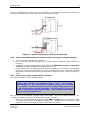
1
® milliGAT Pump 1 684 Sixth Ave FI PO Box 480 Fox Island, WA, 98333 253-549-2223 253-549-2283 milliGAT® Pump Manual User Manual Version 3.07 May 28, 2013 Global FIA, Inc. Tech Support: 253-549-2223 ® milliGAT Pump 2 The information in this manual has been carefully checked and believed to be accurate; however, no responsibility is assumed for inaccuracies. Global FIA, Inc. maintains the right to make changes without further notice to products described in this manual to improve reliability, function, or design. Global FIA, Inc. does not assume any liability arising from the use or application of this product; neither does it convey any license under its patent rights. are trademarks of Intelligent Motion Systems, Inc. Certain copyrighted figures and diagrams used in this manual are used with the permission of Intelligent Motion Systems, Inc. milliGAT® is a registered trademark of Global FIA, Inc. Fox Island, WA, USA. Global FIA, Inc. does not recommend the use of the milliGAT® pump in life support or applications where it may directly or indirectly threaten life or injury. See the Warranty and Disclaimer statement included in the back of this manual. © 2002-2013 Global FIA, Inc. All Rights Reserved User Manual Version 3.07 May 28, 2013 Global FIA, Inc. Tech Support: 253-549-2223 ® milliGAT Pump 3 Contents 1. PRODUCT DESCRIPTION ...................................................................................................................... 6 2. PRINCIPLE OF OPERATION ................................................................................................................. 6 3. INSTALLATION AND USE ..................................................................................................................... 7 3.1 GETTING STARTED ..................................................................................................................................... 7 3.2 PUMPS WITH MICROLYNX CONTROLLER (MG-1, MG-2) ............................................................................. 8 3.2.1 Mounting ........................................................................................................................................... 8 3.2.2 Plumbing ........................................................................................................................................... 9 3.2.3 Electrical connections ...................................................................................................................... 11 3.2.4 Serial communications with a MicroLynx from a host computer using RS-232 .................................. 13 3.2.5 Serial communications with multiple slave devices using a RS-232 to RS-485 converter .................... 13 3.2.6 Communicating with multiple MicroLynx controllers with one MicroLynx as host ............................. 13 3.2.7 Communicating with multiple slave devices using RS-485 with one MicroLynx as host ...................... 14 3.2.8 Pump commands for the MicroLynx controller ................................................................................. 14 3.2.9 Pump units....................................................................................................................................... 15 3.3 PUMPS WITH MDRIVE CONTROLLER (MG-1M17, MG-2M17) ................................................................... 15 3.3.1 Mounting ......................................................................................................................................... 15 3.3.2 Plumbing ......................................................................................................................................... 16 3.3.3 Electrical connections ...................................................................................................................... 16 3.3.4 Serial communications between a MDrive and a host computer using RS-422/485 ............................ 18 3.3.5 Communicating with multiple MDrive controllers ............................................................................ 18 3.3.6 Pump commands for the MDrive controller ...................................................................................... 19 3.3.7 Pump units....................................................................................................................................... 20 3.4 PUMPS WITH MFORCE CONTROLLER (MG-5, MG-5E)............................................................................... 20 3.4.1 Mounting ......................................................................................................................................... 20 3.4.2 Plumbing ......................................................................................................................................... 22 3.4.3 Electrical connections ...................................................................................................................... 22 3.4.4 Serial communications between an MForce controller and a host computer using RS-485 ................ 23 3.4.5 Communicating with multiple MForce controllers ............................................................................ 23 3.4.6 Pump commands for the MForce controller...................................................................................... 23 3.4.7 Pump units....................................................................................................................................... 25 4. PUMP MAINTENANCE AND TROUBLESHOOTING ........................................................................ 25 4.1 MAINTENANCE ........................................................................................................................................ 25 4.1.1 Routine maintenance ........................................................................................................................ 25 4.1.2 Routine cleaning .............................................................................................................................. 25 4.2 TROUBLESHOOTING ................................................................................................................................. 26 4.2.1 Pump leaks ...................................................................................................................................... 26 4.2.2 Pump stalls ...................................................................................................................................... 26 4.2.3 Bubbles in output flow...................................................................................................................... 26 4.2.4 No communication ........................................................................................................................... 26 4.2.5 Status light on controller flashes ...................................................................................................... 27 4.2.6 Flow is not smooth ........................................................................................................................... 27 5. MATERIAL COMPATIBILITY............................................................................................................. 27 5.1 MATERIALS OF CONSTRUCTION ................................................................................................................ 27 5.1.1 PTFE ............................................................................................................................................... 27 5.1.2 PAEK .............................................................................................................................................. 27 5.1.3 Valcon P .......................................................................................................................................... 28 5.1.4 Valcon-E3........................................................................................................................................ 28 5.1.5 Valcon H2........................................................................................................................................ 28 User Manual Global FIA, Inc. Version 3.07 May 28, 2013 Tech Support: 253-549-2223 ® milliGAT Pump 4 5.1.6 Viton® ............................................................................................................................................. 28 5.1.7 Sapphire .......................................................................................................................................... 28 5.1.8 Ceramic ........................................................................................................................................... 28 5.2 GUIDELINES ............................................................................................................................................ 28 6. ACCESSORIES ....................................................................................................................................... 29 6.1 6.2 6.3 6.4 6.5 6.6 PRESSURE RELIEF VALVE (P/N: PRV-100) ................................................................................................ 29 RIGHT ANGLE DRIVE (P/N: RAD) ............................................................................................................. 29 IO SWITCH (P/N: IOS) ............................................................................................................................. 30 USB TO RS-422/485 CONVERTER (P/N: USB-485) ................................................................................... 30 RS-232 TO RS-485 CONVERTER (P/N: SER-485-I).................................................................................... 30 FLOZF DEMO MODE SOFTWARE (P/N: FLOZF-DEMO) ............................................................................. 30 7. SPARE PARTS LIST............................................................................................................................... 30 8. TECHNICAL SUPPORT ........................................................................................................................ 30 9. RETURNING PUMPS TO GLOBAL FIA .............................................................................................. 31 10. OPERATIONAL AND TECHNICAL SPECIFICATIONS.................................................................... 31 11. APPENDIX A – TECHNICAL DETAILS .............................................................................................. 35 11.1 11.2 11.3 11.4 11.5 11.6 11.7 SERIAL CABLE WIRING ......................................................................................................................... 35 STEPPER MOTOR WIRING ...................................................................................................................... 36 DEFAULT VALUES FOR CONTROLLER VARIABLES ................................................................................... 36 CALCULATING MUNIT FOR DIFFERENT MSEL VALUES ......................................................................... 37 BACKLASH CORRECTION ...................................................................................................................... 38 EMBEDDED PROGRAMS ........................................................................................................................ 39 UPGRADING THE FIRMWARE ................................................................................................................. 39 12. APPENDIX B: MICROLYNX COMMANDS ........................................................................................ 41 13. APPENDIX C: MDRIVE AND MFORCE COMMANDS ...................................................................... 42 14. WARRANTY AND DISCLAIMER......................................................................................................... 43 List of Figures Figure 1: milliGAT pump cross section ..................................................................................... 7 Figure 2: Mounting points and external dimensions for milliGAT LF (MG-1) .................................... 9 Figure 3: 10-32 fittings on 1/16" (1.6 mm) OD tubing .............................................................. 10 Figure 4: ¼-28 fittings on 1/16" (1.6 mm) OD tubing and 1/8" (3.1 mm) OD tubing ......................... 10 Figure 5: MicroLynx cabling diagram with RS-232 connection ..................................................... 11 Figure 6: MicroLynx communication cabling with RS-485 connection............................................ 11 Figure 7: MicroLynx communication cabling with RS-232 and RS-485 connections ......................... 12 Figure 8: Power connection for MicroLynx and Pump ................................................................. 12 Figure 9: Mounting points and external dimensions for milliGAT LF with integrated controller (MG1M17) ........................................................................................................................ 16 Figure 10: MDrive cabling diagram with RS-422/485 connection ................................................. 17 Figure 11: MDrive cable diagram for multiple devices................................................................ 17 Figure 12: Power connection for MicroLynx and Pump ............................................................... 18 Figure 13: Mounting points and external dimensions for milliGAT with MForce controller (MG-5)....... 21 Figure 14: Motor and serial cable connections for MForce controller ............................................. 22 Figure 15: Pressure relief valve ............................................................................................. 29 Figure 16: Right angle drive ................................................................................................. 29 Figure 17: Pin outs on MicroLynx ........................................................................................... 36 User Manual Version 3.07 May 28, 2013 Global FIA, Inc. Tech Support: 253-549-2223 ® milliGAT Pump Table Table Table Table Table Table Table Table Table Table Table Table Table Table Table Table Table Table Table Table 5 List of Tables 1: Pump model numbers............................................................................................... 6 2: Party mode address settings ..................................................................................... 14 3: Basic pump commands for the MicroLynx.................................................................... 15 4: Sample commands for the MicroLynx ......................................................................... 15 5: Basic pump commands for the MDrive 17 ................................................................... 19 6: Sample commands for the MDrive 17 ......................................................................... 20 7: Pump commands for the MDrive 17 with backlash compensation .................................... 20 8: Power connections for MForce ................................................................................... 22 9: Pin outs for MForce RS-422 serial port........................................................................ 23 10: Basic pump commands for the MForce Controller ........................................................ 24 11: Sample commands for the MForce Controller ............................................................. 24 12: Pump commands for the MForce with backlash compensation ....................................... 25 13: Spare parts list ..................................................................................................... 30 14: RS-232 pin outs.................................................................................................... 35 15: RS-485 pin outs.................................................................................................... 35 16: RS-232 / RS-485 pin outs ...................................................................................... 35 17: Motor wiring......................................................................................................... 36 18: Factory settings for controller variables..................................................................... 37 19: Flow rate conversion table ...................................................................................... 37 20: Automated backlash compensation .......................................................................... 38 User Manual Version 3.07 May 28, 2013 Global FIA, Inc. Tech Support: 253-549-2223 ® milliGAT Pump 6 1. Product Description The microprocessor-controlled milliGAT® pump* consists of a pump head with appropriate fluid line connectors, a motor and gearbox assembly, a stepper motor controller, a switch-mode power supply (100 – 240 VAC to 24 VDC), and various cables. Several models of the pump are available and are listed in the following table: Table 1: Pump model numbers Model MG-1 MG-1M17 MG-1M17-EE Pump MG-LF low flow MG-LF low flow MG-LF low flow MG-2 MG-2M17 MG-2M17-EE MG-HF high flow MG-HF high flow MG-HF high flow MG-5 MG-5E MG-LF low flow MG-LF low flow Gearbox and Motor 1.8º stepper motor / 4.75x gearbox 1.8º stepper motor / 4.75x gearbox 1.8º stepper motor / 4.75x gearbox / external encoder 1.8º stepper motor / 10x gearbox 1.8º stepper motor / 10x gearbox 1.8º stepper motor / 10x gearbox / external encoder 0.9º stepper motor / 22.56x gearbox 0.9º stepper motor / 22.56x gearbox / external encoder Controller ML-4 – MicroLynx MDrive 17 plus MDrive 17 plus2 ML-4 – MicroLynx MDrive 17 plus MDrive 17 plus2 MForce 17 plus MForce 17 plus2 The performance characteristics of each of these pumps are given in §10. 2. Principle of operation The central component in the pump is a cylindrical rotor that is fitted with four equally spaced pistons (two are shown in Figure 1). This rotor seals against the stator end cap. The stator end cap has an inlet and outlet port. These ports are coupled to an inlet channel in the shape of an arc and a similar outlet channel in the stator cap. As the rotor turns, a cam governs the back and forth displacement of the spring-loaded pistons with a piston stroke of 1/8” (3mm). The diameter of the pistons of the HF pump is larger than the pistons of the LF pump. As the motor turns the rotor, one piston is dispensing into the outlet channel, one piston is filling from the inlet channel and the other two are moving between the inlet and outlet channels. The cam has been engineered to ensure a smooth transition when one piston hands off to the next. * US Pat No. 6,079,313 issued to Global FIA, Inc. User Manual Version 3.07 May 28, 2013 Global FIA, Inc. Tech Support: 253-549-2223 ® milliGAT Pump 7 Figure 1: milliGAT pump cross section A stepper motor governs rotation rate and direction. Flow direction is determined by the direction of rotation. Flow rate is determined by the rate of rotation. The metering capability of the pump is determined by the accuracy of the stepper motor working in micro-step mode. In addition to various levels of gearing, the stepper motor is operated in a mode where every stepper motor step is divided into 256 micro-steps. For the low flow (LF) pump one revolution of the pump displaces 100 L and for the high flow (HF) pump, one revolution displaces 630 L. The volume per micro-step is dependent on motor, gearing, and pump used and can be calculated using the formula given on page 38. In the event of a deadhead blockage, the backpressure overcomes the spring that holds the rotor against the stator. The rotor of the pump moves away from the stator and fluid leaks into the pump internals and eventually from one of the pump’s leak ports. If this occurs, the leakage must be well flushed from the pump using distilled water and isopropyl alcohol to prevent permanent damage (see §4.2.1 for more detailed instructions on dealing with a leak). While care has been taken to ensure a smooth transition from one piston to the next, some users with sensors that are extremely sensitive to flow may notice a small perturbation as one piston hands off to the next. The pistons are Teflon™ tipped and the Teflon tip is longer than the piston stroke thereby ensuring that the wetted surface of the piston chamber is not exposed to air. This has a positive implication for wear life of the pistons as crystals of dried dissolved solids cannot form and scratch the seal surface. The milliGAT® is a self-priming positive displacement pump and can tolerate gas in the fluid lines. An animated depiction of the operation of the pump is given at http://www.vici.com/liqhand/m6.php 3. Installation and use 3.1 Getting started In order to operate the pump you must: Mount the pump and controller using the provided mounting points. User Manual Version 3.07 May 28, 2013 Global FIA, Inc. Tech Support: 253-549-2223 ® milliGAT Pump 8 For best results, the milliGAT pump must be orientated with its ports facing up. If the pump is orientated in any other direction, bubbles may be trapped in the internal chambers of the pump. This will have an adverse affect on accuracy and smoothness of flow. Plumb tubing to the inlet and outlet ports of the pump. The inlet is labeled with an A and the outlet is labeled with a B. Connect the serial port on the pump controller to a suitable serial port on a computer. For systems with separate stepper motor controllers, connect the motor to the controller. Connect the power supply and power up the pump. Run a suitable serial port terminal emulation program. There are several options for this step. Many users simply make use of the Terminal Emulation program called Hyper Terminal that comes packaged with most Windows operating systems. A more specialized Terminal emulation program called IMS Terminal is supplied with the disk that was supplied with the pump or it can be downloaded from http://www.imshome.com/software_interfaces.html. A third and very powerful option is to use the demo version of FloZF written by Global FIA and available for download at http://www.globalfia.com/software.html Subsequent sections will describe each of these steps in more detail and provide the command structure for each model of the pump. 3.2 3.2.1 Pumps with MicroLynx controller (MG-1, MG-2) Mounting The mounting points of the pump and controller are given in Figure 2 together with the external dimensions of each module. Because the high flow pump (HF) makes use of a dual stage gearbox, its enclosure is 1” (25.4 mm) longer than the low flow pump. All other dimensions are the same. The controller should be mounted in such a way to allow adequate cooling and circulation of air around the controller. User Manual Version 3.07 May 28, 2013 Global FIA, Inc. Tech Support: 253-549-2223 ® milliGAT Pump 9 Figure 2: Mounting points and external dimensions for milliGAT LF (MG-1) 3.2.2 Plumbing The low flow milliGAT® pump (MG-1) has two 10-32 threaded female ports. The high flow pump (MG-2) is equipped with two ¼-28 female ports. If you look carefully, you will see that they are labeled A and B. Port A is the inlet and port B is the outlet for positive pump movements. If you plan on using 1/32” (0.8 mm) OD tubing with the low flow pump, care must be taken not to insert the tubing too far into the pump and so damage the pump rotor. A fitting set suited for 1/32” OD tubing that includes a 6-40 finger-tight fitting and an adapter to the 10-32 female port in the pump is available (see §7 for part numbers) User Manual Version 3.07 May 28, 2013 Global FIA, Inc. Tech Support: 253-549-2223 ® milliGAT Pump 10 A set of 10-32 finger-tight fittings and ferrules are supplied with the low flow pump. These fittings are suitable for 1/16” (1.6 mm) OD tubing. Figure 3 is a picture of 10-32 fittings correctly fitted on PFA tubing. Figure 3: 10-32 fittings on 1/16" (1.6 mm) OD tubing For the high flow pump, ¼-28 fittings are supplied for either 1/16” (1.6 mm) or 1/8” (3.1 mm) OD tubing. Figure 4: ¼-28 fittings on 1/16" (1.6 mm) OD tubing and 1/8" (3.1 mm) OD tubing The following instructions describe how to make a good fitting connection. The leak-tightness and integrity of the connection is dependent upon tubing preparation and the correct procedure in making up the fitting. It is important to use the fittings supplied with the pump. Fittings from other suppliers have been known to damage the pump. 1. To ensure a good seal and avoid unswept volumes, make a square cut of the tubing using a sharp blade or tubing cutter. Make sure that the end of the tube is free of burs or cut debris. 2. Slide the nut and ferrule onto the tubing in the order shown in the pictures above. 3. Insert this tubing into the female port on the pump and screw the nut in two or three turns. 4. Push the tubing all the way forward into the detail so that it seats firmly. This is essential for a proper zero dead volume connection. 5. Tighten the nut in the port until it is finger-tight. Do not over tighten the fittings as you could damage the threads of the port. 6. Remove the fitting and inspect it. The tubing should protrude past the ferrule by approximately 2mm for the 10-32 fittings and should be flush with the ferrule for the ¼-28 fittings. 7. When made up properly, the ferrule may be free to spin axially on the tubing, but should have no lateral movement along the tubing. If the ferrule moves laterally, re-install the fitting into the detail and tighten it another 1/8 turn past finger tight. 8. Remove, re-inspect, and repeat, if necessary. User Manual Version 3.07 May 28, 2013 Global FIA, Inc. Tech Support: 253-549-2223 ® milliGAT Pump 3.2.3 11 Electrical connections NOTE! It is a good practice to only apply power to the power supply after all connections have been made. Failure to do so may destroy the controller. Take precautions to avoid static discharges to the controller. Figure 5 shows how to connect an RS-232 serial port to the MicroLynx. For computers such as Laptops equipped only with USB ports, a USB to RS-232 converter can be used. One that has been found to be reliable is available from Global FIA (see §6). Figure 5: MicroLynx cabling diagram with RS-232 connection Figure 6 indicates two possibilities for connecting the controller to an RS-485 port. In the inset, the RS-485 pins on the MicroLynx are connected to the A and B pins of a 2-wire RS-485 port. In the main diagram, the Receive pins on the MicroLynx are connected to the corresponding Transmit pins on the RS-485 port and the Transmit pins on the MicroLynx are connected to the Receive pins on the RS-485 port. Custom cables to suit user requirements are available form Global FIA. Figure 6: MicroLynx communication cabling with RS-485 connection User Manual Version 3.07 May 28, 2013 Global FIA, Inc. Tech Support: 253-549-2223 ® milliGAT Pump 12 In a third possible arrangement, the MicroLynx is coupled to the PC via a RS-232 connection and acts as a host for communication to other devices on an RS-485 network. This arrangement is represented schematically in Figure 7 for subsequent communication on a 2-wire RS-485 loop. Communication on a 4-wire RS-485 loop can be derived from this figure. Figure 7: MicroLynx communication cabling with RS-232 and RS-485 connections The pin outs for the serial port are given in Table 14 and Table 15. Figure 8 indicates how the pump and power supply are to be connected to the MicroLynx. Caution – The power connector is keyed - be careful not to plug the power connector in incorrectly – this could result in overheating and damage to the pump motor and MicroLynx-4 controller. The 24V power wires are closest to the edge of the controller and power status LED. Figure 8: Power connection for MicroLynx and Pump User Manual Version 3.07 May 28, 2013 Global FIA, Inc. Tech Support: 253-549-2223 ® milliGAT Pump 3.2.4 13 Serial communications with a MicroLynx from a host computer using RS-232 1. Connect the cables as indicated in Figure 5. 2. Run a Terminal emulation program such as IMS Terminal, Windows Hyper Terminal or the FloZF terminal emulator. 3. Configure the communication settings in the software to 9600 baud, no parity, 8 data bits, 1 stop bit, and with no hardware or software flow control. 4. Power up the pump. An identifying string should be displayed on the screen, or the resident program (if there is one) will commence. If not, power down the pump. Ensure that all cables are properly connected and that the communication settings are correct. Power the pump up again. 5. You can also type PRINT VER<CR> where <CR> is the enter key, and the controller should reply with the firmware version. 3.2.5 Serial communications with multiple slave devices using a RS-232 to RS-485 converter 1. Using an RS-232 connection set the following system variables on each of the slave devices before changing the address HOST=0 ECHO 2=0 for full duplex 4-wire RS-485 communication or HOST=0 ECHO 2=1 for half duplex 2-wire RS-485 communication 2. Set up the addresses on each slave device. 3. Connect cables as shown in Figure 6. 4. Follow steps 2 through 4 in §3.2.4. Precede each command with the address of the device – addresses are case sensitive and end each command with Ctrl-J. 3.2.6 Communicating with multiple MicroLynx controllers with one MicroLynx as host This mode of operation is also called Party mode. 1. Using an RS-232 connection to only the first MicroLynx, set the following system variables before changing the address on the device. HOST=1 ECHO 2=0 for full duplex 4-wire RS-485 communication or HOST=1 ECHO 2=1 for half duplex 2-wire RS-485 communication 2. Save these settings by issuing the SAVE command. This controller is now designated as the host. 3. Connect cables as shown in Figure 7 and Table 16 to the slave controllers. It is preferable to use 4-wire RS-485 communication. Note that the RX pins on the host are wired to the TX pins on the slave controllers and the TX pins on the host are wired to the RX pins on the slave controllers. Connection from one slave controller to the next is RX to RX and TX to TX. 4. Set the address switches on the side of each controller to a unique address per Table 2. Note addresses are case sensitive. 5. Cycle power (remove power, pause until LED goes out, then re-apply power) or send a Ctrl-C from the keyboard. The MicroLynx is now in party mode and all communications directed to this unit must begin with the address you picked from Table 2. Furthermore, all communications must be terminated with a Ctrl-J (line feed) instead of a carriage return (Enter key). There will not be any sign on message. All controllers will now be in party mode. NOTE: while in party mode, you must precede all commands with the address and terminate all commands with a Ctrl-J! For example, ASlew 10[Ctrl-J]. If you press Enter by mistake, just press Ctrl-J to send the command. If commands appear not to be getting through, press Ctrl-J to set all controllers to receive mode again. You can configure CR to send CR+LF in most terminal emulation packages. Then when you press Enter, a CR and LF (Ctrl-J) will be sent. User Manual Version 3.07 May 28, 2013 Global FIA, Inc. Tech Support: 253-549-2223 ® milliGAT Pump 14 6. Test by sending the command APRINT VER[Ctrl-J] if A is a valid address. You should receive the line; VER =x.xx. 7. To obtain full duplex communication for each device type aECHO 2=0[Ctrl-J], where “a” is the devices address from Table 2. Save the new setting by typing aSAVE[Ctrl-J]. When using the dip switches to set addresses, all addresses are in uppercase. If you use a lower case addresses or an invalid address, all MicroLynx controllers will ignore further input until Ctrl-J is pressed. 8. When in party mode there is no sign on message, but you can check for communication to a specific device by monitoring the pilot light and then press Ctrl-C, the pilot light should go off and then on again. Table 2: Party mode address settings Address None A B C D E F G 3.2.7 A2 Off Off Off Off On On On On A1 Off Off On On Off Off On On A0 Off On Off On Off On Off On Communicating with multiple slave devices using RS-485 with one MicroLynx as host 1. Using an RS-232 connection set the following system variables for the host MicroLynx before changing the address of the MicroLynx HOST=1 ECHO 2=0 for full duplex 4-wire RS-485 communication or HOST=1 ECHO 2=1 for half duplex 2-wire RS-485 communication 2. Using an RS-232 connection set the following system variables on each of the slave devices before changing the address of the device HOST=0 ECHO 2=0 for full duplex 4-wire RS-485 communication or HOST=0 ECHO 2=1 for half duplex 2-wire RS-485 communication 3. Set up the addresses on each slave device. 4. Connect cables as shown in Figure 7. 5. Follow steps 2 through 4 in §3.2.4. 6. Any commands sent for devices down line of the host controller will be relayed by the host controller. Replies will be passed through to the computer by the host controller 3.2.8 Pump commands for the MicroLynx controller Once serial communication has been established between the computer and the MicroLynx, simply type the commands from the terminal program (or the Terminal window of IMS Terminal) or issue them from your custom software to activate the pump. Appendix B: MicroLynx Commands provides a list of selected MicroLynx commands. Further details on the MicroLynx controller can be found in the MicroLynx hardware or software manual which can be downloaded from http://www.imshome.com/manuals.html. Table 3 provides the basic commands necessary to control the pump. When the controller receives a valid command it returns a > prompt (when not in party mode), if the command is not valid, the controller returns a ? prompt. User Manual Version 3.07 May 28, 2013 Global FIA, Inc. Tech Support: 253-549-2223 ® milliGAT Pump 15 Table 3: Basic pump commands for the MicroLynx SLEW Description: Pump continuously at the specified flow rate Example: SLEW=20 VM Description: Sets the flow rate for pump commands Example: VM=20 MOVR Description: Pumps the specified volume, pump direction is determined by the sign Example: MOVR=–100 SSTP Description: Stops pump movement* Example: SSTP Min Max Units 0.004 167 L/sec Min Max Units 0.004 167 L/sec Min Max Units ±0.001 ± 1015 L Min Max Units Table 4 provides a few examples with descriptions given in the first column and the required commands given in the second column. Table 4: Sample commands for the MicroLynx Description Aspirate† 0.5L at 5L/sec Dispense 1000L at 100L/sec Pump continuously at 50L/sec Stop the pump Re-establish pump factory settings Save all present settings to non-volatile RAM Command VM=5 MOVR=-0.5 VM=100 MOVR=1000 SLEW=50 SSTP INIT SAVE Each command is sent to the controller by pressing the Enter key (except when in party mode, then Ctrl-J is used). When entering these commands, always ensure that the controller returns a > prompt. If it returns a ? prompt, then there is an error in the command and you must retype it. You can clear the error by typing PRINT ERROR. Error codes are given in the MicroLynx software manual. 3.2.9 Pump units The default units for the pump when the MicroLynx controller is used are L (volume), L/sec (flow rate and slew rate), and L/sec2 (flow acceleration rate). The conversion factor between volumetric units and micro steps is given by the controller variable MUNIT. The value of MUNIT can be determined using the equation on page 38. You can determine the present value of MUNIT by typing PRINT MUNIT<CR>. 3.3 3.3.1 Pumps with MDrive controller (MG-1M17, MG-2M17) Mounting For these pumps, the controller in integrated with motor and so there is no separate controller. The mounting points of the pump and controller are given in Figure 9 together with the external dimensions of each module. Because the high flow pump makes use of a dual stage gearbox, the motor and gear assembly is 0.52” (13 mm) longer than the low flow pump. All other dimensions are the same. * † Pressing the ESC key will also halt a pump action Switch inlet and outlet ports if flow direction is reversed User Manual Version 3.07 May 28, 2013 Global FIA, Inc. Tech Support: 253-549-2223 ® milliGAT Pump 16 The pump should be mounted in such a way to allow adequate cooling and circulation of air around the controller. 1 in 1.81 in 1.66 in 3.823 in 2.725 in Ø1.495 in 8-32 Thread (2X) 2.31 in 7.246 in Figure 9: Mounting points and external dimensions for milliGAT LF with integrated controller (MG-1M17) 3.3.2 Plumbing Details for the plumbing of these pumps is the same as for the pumps that use the MicroLynx controller and are given in §3.2.2 3.3.3 Electrical connections NOTE! It is a good practice to only apply power to the power supply after all connections have been made. Failure to do so may destroy the controller. Take precautions to avoid static discharges to the controller. The MDrive controller is equipped with an RS-485 (also called RS-422) port for communication. Figure 10 shows how to make a serial connection to the MDrive. A USB to RS-422/485 or RS-232 to RS422/485 converter is available for computers that do not have the correct ports. Part numbers are listed in §6. The mating plug for this connector on the controller is Amp 1-111623-8. User Manual Version 3.07 May 28, 2013 Global FIA, Inc. Tech Support: 253-549-2223 ® milliGAT Pump 17 Figure 10: MDrive cabling diagram with RS-422/485 connection Figure 11: MDrive cable diagram for multiple devices Figure 11 shows how multiple devices can be controlled from a single serial port. Each device requires a unique address (or Device Name - DN). §3.3.5 describes how to configure each drive for this mode of operation. User Manual Version 3.07 May 28, 2013 Global FIA, Inc. Tech Support: 253-549-2223 ® milliGAT Pump 18 Figure 12 indicates how to connect power to the MDrive. Two models of the MDrive are shown, the one with flying leads and the other with a seven pin pluggable terminal. Figure 12: Power connection for MicroLynx and Pump 3.3.4 Serial communications between a MDrive and a host computer using RS-422/485 1. Connect the cables as indicated in Figure 10. 2. Run a Terminal emulation program such as IMS Terminal, Windows Hyper Terminal or ProComm. 3. Configure the communication settings in the software to 9600 baud, no parity, 8 data bits, 1 stop bit, and with no hardware or software flow control. 4. Power up the pump. An identifying string should be displayed on the screen, or the resident program (if there is one) will commence. If not, power down the pump. Ensure that all cables are properly connected and that the communication settings are correct. Power the pump up again. 3.3.5 Communicating with multiple MDrive controllers This mode of operation is also called Party mode. NOTE: when in party mode, you must precede all commands with the address and terminate all commands with a Ctrl-J! For example, ASL 10000[Ctrl-J]. If you press Enter by mistake, just press Ctrl-J to send the command. If commands appear not to be getting through, press Ctrl-J to set all controllers to receive mode again. You can configure CR to send CR+LF in most terminal emulation packages. Then when you press Enter, a CR and LF (Ctrl-J) will be sent. Each drive has to be assigned a unique Device Name (DN). The factory default address is “A”. Connect to one MDrive at a time and set the following drive variables: 1. Once you have established communication type, ADN=”a”<CR> where a is the device name (the device name can be an alphabetic character A-Z). Addresses are case sensitive. Once named, the device name must precede the instruction to that drive. User Manual Version 3.07 May 28, 2013 Global FIA, Inc. Tech Support: 253-549-2223 ® milliGAT Pump 19 2. Type aS<CR> to save the address to non-volatile memory. 3. Once all devices have been configured, then connect them as indicated in Figure 11. When in party mode there is no sign on message. Some embedded programs may display device addresses at startup. 3.3.6 Pump commands for the MDrive controller Once serial communication has been established between the computer and the MDrive, simply type the commands from the terminal program (or the Terminal window of IMS Terminal) or issue them from your custom software to activate the pump. Appendix C: MDrive and MForce commands provides a list of selected MDrive commands. Further details on the MDrive controller can be found in the MDrive Motion Control hardware or software manual (see http://www.imshome.com/manuals.html). Table 5 provides the basic commands necessary to control a pump where the device name has not been set. For the MDrive, all variables (e.g. flow rates) must be integers. Pump move, flow rate and acceleration settings are given in microsteps. You can convert to L by multiplying the desired L value by EU. EU stands for engineering units and represents the number of micro steps in a L. For desired volumetric settings that are not integers, you will have to calculate the equivalent micro steps and then issue the appropriate command, e.g. for EU=2432, and a desired flow rate of 0.1 L/sec use the command VM=243 Table 5: Basic pump commands for the MDrive 17 SL Description: Pump continuously at the specified flow rate Example: SL=20*EU Min Max Units 1 167 L/sec VM Description: Sets the flow rate for pump commands Example: VM=20*EU Min Max Units 1 167 L/sec Description: Pumps the specified volume, pump direction is determined by the sign Example: MR=–100*EU Min Max Units MR 1 ± 1015 L SL=0 Description: Stops pump movement* Example: SL=0 Min Max Units The MDrive does not have built-in backlash correction. A small program has been installed on the MDrive which compensates for backlash. Backlash comes into play when you change pump direction. There are small tolerances in the drive train and gear box that must be taken up before the pump actually starts to move. So when the direction of flow changes, a small volume equal to the backlash must be added to the desired dispense volume. The embedded program takes care of this but you must use a different command set to aspirate or dispense a particular volume. VL specifies the volume in L to pump. EX FL runs the embedded program that completes the move with backlash compensation where appropriate. Table 7 provides the commands to use if you need backlash compensation. Table 6 provides a few examples with descriptions given in the first column and the required commands given in the second column. * Pressing the ESC key will also halt a pump action User Manual Version 3.07 May 28, 2013 Global FIA, Inc. Tech Support: 253-549-2223 ® milliGAT Pump 20 Table 6: Sample commands for the MDrive 17 Description Aspirate* 10 L at 5L/sec Dispense 1000L at 100L/sec Pump continuously at 50L/sec Stop the pump Re-establish pump factory settings Save all present settings to non-volatile RAM Command AVM=5*EU AMR=-10*EU AVM=100*EU AMR=1000*EU ASL=50*EU ASL=0 AEX IZ AS Each command is sent to the controller by pressing the Ctrl-J. configured with a device name of A. For this example the MDrive was Table 7: Pump commands for the MDrive 17 with backlash compensation VL Description: Set the desired volume to aspirate or dispense Example: VL=25 Min 1 ±1015 Ex FL Description: Execute the pump move Example: EX FL Min Max VS Description: Set the desired volume in steps Example: VS=1216 Min 1 ±1015 steps Ex FS Description: Execute the pump move for volume in steps Example: EX FL Min Max Units 3.3.7 Max Max Units L Units Units Pump units The default units for the pump when the MDrive controller is used are steps. The conversion factor between volumetric units and steps is given by the controller variable EU. The value of EU can be determined using the equation for MUNIT on page 38 (EU=MUNIT). 3.4 3.4.1 Pumps with MForce controller (MG-5, MG-5E) Mounting These pumps have a standalone controller. The mounting points for the pump and controller are given in Figure 13 for the device without external encoder. If the motor is equipped with an external encoder, the motor and gearbox will be 5/8” (16 mm) longer * Switch inlet and outlet ports if flow direction is reversed User Manual Version 3.07 May 28, 2013 Global FIA, Inc. Tech Support: 253-549-2223 ® milliGAT Pump 21 Ø1.5 in 8-32 Thread (2X) 1.66 in 1.81 in 1 in 3.823 in 2.06 in 0.95 in 7.516 in Figure 13: Mounting points and external dimensions for milliGAT with MForce controller (MG-5) User Manual Version 3.07 May 28, 2013 Global FIA, Inc. Tech Support: 253-549-2223 ® milliGAT Pump 22 The controller should be mounted in such a way to allow adequate cooling and circulation of air around the controller. 3.4.2 Plumbing Details for the plumbing of these pumps is the same as for the pumps that use the MicroLynx controller and are given in §3.2.2 3.4.3 Electrical connections NOTE! It is a good practice to only apply power to the power supply after all connections have been made. Failure to do so may destroy the controller. Take precautions to avoid static discharges to the controller. Ensure that electrical connections are made according to Table 8. Table 8: Power connections for MForce Pin 15 16 Function Power 24VDC Power Ground Connect the power, motor and serial control cables as shown in Figure 14 Figure 14: Motor and serial cable connections for MForce controller The MForce controller is equipped with an RS-422 port for device control. The mating plug for this connector is a SAMTEC - TCSD-05-01-N. Global FIA can provide a USB to RS-422 converter cable (P/N: USB-RS-422) or other custom ordered cables to suit a user’s application. User Manual Version 3.07 May 28, 2013 Global FIA, Inc. Tech Support: 253-549-2223 ® milliGAT Pump 23 Table 9: Pin outs for MForce RS-422 serial port Pin 1 2 3 4 5 6 7 8 9 10 Function TX+ TXRX+ RXAux Logic RX+ RXTXTX+ Gnd RS-422 allows the possibility of connecting multiple devices to a single serial port. For multiple devices from a single serial port, each device requires a unique device name (DN). The default address for single MForce devices is “A”. §3.4.5 describes how to configure each drive for this mode of operation. 3.4.4 Serial communications between an MForce controller and a host computer using RS485 1. Connect the cables as indicated in and Figure 14 and Table 9. If you use the USB-422 you can download the driver for the virtual USB serial port from the ftdi web site at http://www.ftdichip.com/Drivers/VCP.htm 2. Run a Terminal emulation program such as IMS Terminal, Windows Hyper Terminal or ProComm. 3. Configure the communication settings in the software to 9600 baud, no parity, 8 data bits, 1 stop bit, and with no hardware or software flow control. 4. Power up the pump. An identifying string or > prompt should be displayed on the screen. If not, power down the pump. Ensure that all cables are properly connected and that the communication settings are correct. Power the pump up again. 3.4.5 Communicating with multiple MForce controllers 1. Each drive has to be assigned a unique Device Name (DN). The factory default address is “A”. Connect to one MForce at a time and set the following drive variables: 2. Once you have established communication type, ADN=”a” where a is the device name (the device name can be an alphabetic character A-Z). Addresses are case sensitive. Once named, the device name must precede the instruction to that drive. 3. aS to save the address to non-volatile memory. NOTE: All commands must be terminated with a CR and LF! For example, AVM10000<CR><LF>. You can configure CR to send CR+LF in most terminal emulation packages. Then when you press Enter, a CR and LF will be sent. 3.4.6 Pump commands for the MForce controller Once serial communication has been established between the computer and the MForce simply type the commands from the terminal program or issue them from your custom software to activate the pump. Appendix C: MDrive and MForce commands provides a list of selected MForce commands. Further details on the MForce controller can be found in the Motion Control MForce hardware manual (see http://motion.schneider-electric.com/products/mforce_microdrive_mfi.html). Table 10 provides the basic commands necessary to control a pump where the device address is the default address A. For the MForce, all variables must be integers. Pump move, flow rate and acceleration settings are given in microsteps. User Manual Version 3.07 May 28, 2013 Global FIA, Inc. Tech Support: 253-549-2223 ® milliGAT Pump 24 Table 10: Basic pump commands for the MForce Controller SL Description: Pump continuously at the specified flow rate Example: ASL 231040 VM Description: Sets the flow rate for pump commands Example: AVM 23104 Min Max Units 100 231040 steps/ sec Min Max Units 100 231040 steps/ sec Units Description: Pumps the specified volume, pump direction is determined by the sign Example: AMR 2310400 Min Max MR 10 ± 2x10 steps SL Description: Stops pump movement Example: ASL 0 Min Max Units 9 Commands assume a module address of A. Table 11 provides a few examples with descriptions given in the first column and the required commands given in the second column. For this example the MForce controller is configured with an address of A. Table 11: Sample commands for the MForce Controller Description Aspirate* 10 L† at 2L/sec Dispense 100L at 1L/sec Pump continuously at 20nL/sec Stop the pump Re-establish pump factory settings Save all present settings to non-volatile RAM Command AVM 46208 AMR -231040 AVM 23104 AMR 2310400 ASL 462 ASL 0 AEX IZ AS Each command is sent to the controller by pressing the Enter key <CR>. The software should be configured to send <CR> + <LF> when Enter is pressed. The MDrive does not have built-in backlash correction. A small program has been installed on the MDrive which compensates for backlash. Backlash comes into play when you change pump direction. There are small tolerances in the drive train and gear box that must be taken up before the pump actually starts to move. So when the direction of flow changes, a small volume equal to the backlash must be added to the desired dispense volume. The embedded program takes care of this but you must use a different command set to aspirate or dispense a particular volume. VL specifies the volume in L to pump. EX FL runs the embedded program that completes the move with backlash compensation where appropriate. Table 12 provides the commands to use if you need backlash compensation. * † Switch inlet and outlet ports if flow direction is reversed There are 23,104 steps per L User Manual Version 3.07 May 28, 2013 Global FIA, Inc. Tech Support: 253-549-2223 ® milliGAT Pump 25 Table 12: Pump commands for the MForce with backlash compensation VL Description: Set the desired volume to aspirate or dispense Example: AVL=25 Min 1 ±1015 Ex FL Description: Execute the pump move Example: AEX FL Min Max Units VS Description: Set the desired volume in steps Example: AVS=1216 Min Max Units Ex FS Description: Execute the pump move for volume in steps Example: AEX FS Min 1 Max ±10 15 Max Units L steps Units Example commands assume a module address of A. Each command is sent to the controller by pressing the Enter key <CR>. The software should be configured to send <CR> + <LF> when Enter is pressed. 3.4.7 Pump units The default units for the pump when the MForce controller is used are microsteps. There are 23,104 steps in a L. 4. Pump maintenance and troubleshooting 4.1 Maintenance There are NO user serviceable parts inside the pump. Opening the pump by removing, or even loosening the hex bolts that hold the pump together will void the pump’s Limited Warranty. To obtain optimum performance and maximum life from the milliGAT® pump, it is important to follow the recommended cleaning and maintenance instructions. 4.1.1 Routine maintenance Flush the pump thoroughly with distilled or de-ionized water after each use. Store the pump dry. Avoid running the pump dry for extended periods. The pump is self priming and will dispel entrapped bubbles when orientated vertically. Inspect the pump for leaks and correct any problems immediately. Liquid entering the motor housing could damage the motor and gear assembly. The pump is equipped with a leak port. Leakage from this port indicates excessive back pressure and unreliable pumping action. Wipe up all spills on and around the pump immediately. If fluid is seen coming from the leak port, flush the internals of the pump through the leak port with distilled water and then isopropyl alcohol (IPA) and allow it to dry before further use. If the flow manifold is such that leaks through the leak port are frequent, then it is a good idea to incorporate a pressure relief valve (Part No.: PRV-100) downstream of the pump to allow over pressure situations to leak safely to waste. 4.1.2 Routine cleaning The pump fluid path can be cleaned with one of the following cleaning solutions 1. Weak detergent wash. We have found Micro-90* to be a good general purpose detergent. * http://www.coleparmer.com/Catalog/product_index.asp?cls=504 User Manual Version 3.07 May 28, 2013 Global FIA, Inc. Tech Support: 253-549-2223 ® milliGAT Pump 26 2. Weak acid and base wash: pump 5 mL of 0.1N NaOH followed by 5 mL of water followed by 5 mL of 0.1N HCl, followed by 10 mL of water. 3. Weak bleach wash: pump 5 mL of a 10% beach solution followed by 10 mL of water. The pump is not amenable to autoclaving. High temperatures compromise pump seals. cleaning procedures should be employed to ensure sterility. 4.2 4.2.1 Chemical Troubleshooting Pump leaks The most frequent cause of leaks is over pressurization of the pump. The maximum pressure capability of the pump is 100 psi (approx. 7 bar). If this pressure is exceed by pumping against a dead head or blockage or by using a high flow rate in very narrow bore tubing, then the rotor moves away from the stator and fluid leaks into the pump internals. There are three leak ports on the pump. One is in the stator and the other two are in the side of the pump housing. If fluid leaks into the pumps internals, eventually it will leak from one of the leak ports. If this occurs it is important to flush out the pump internals through the leak port with distilled water and isopropyl alcohol. This is particular important if the leak fluid is corrosive or has a high dissolved solids content. In most cases, simply flushing out the pump in this way and removing the source of back pressure will get the pump back to good working condition. If the leak fluid has done more permanent damage, then the pump will have to be returned for refurbishment. 4.2.2 Pump stalls When the torque of the pump exceeds the torque output of the motor, the pump will stall. Depending on the flow rate, a characteristic growling sound or vibration or ticking and no flow of the fluid will indicate that the pump is stalling. There are a few possible causes of this problem: 1. Wires or connections are loose. If the wires between the pump and controller are loose or damaged, the torque output of the motor will be less than optimal. Repair wires or tighten connections to remedy 2. Check the run current. The run current determines the current which is sent to the motor. For the MicroLynx the run current (MRC) is 35. This can be increased to 40 (MRC=40). On the MDrive the default run current (RC) is 60. This can be increased 80 (RC=80). If it is increased, the motor will run a little hotter than normal but it will not harm the motor or pump. A higher current will give a higher torque. 3. Check the voltage. The controller will accept a voltage between 12 and 48 VDC. The supplied power supply has an output voltage of 24VDC. Slightly higher torque is achievable if a power supply with a higher voltage output is installed. Although the controller will still work with an input voltage of 12 VDC. It is doubtful whether 12VDC will provide enough power to turn the pump. 4. Certain solvents cause the wetted components to swell. Some organic solvents will cause slight swelling of the rotor or stator. A small increase in certain dimensions could cause the pump to stall. Flush out the organic solvent (this may require manual turning of the pump) with distilled water and allow it to dry out and stand for a while. Under certain conditions, the polymers will shrink back to the correct size and the pump will again begin to function. Under these conditions, the pump is probably not suited to such solvents. 4.2.3 Bubbles in output flow When a continuous stream of bubbles is in the pump outlet but not the inlet, the most likely cause is a poor fluid connection usually in the inlet. Ensure that the tubing is cut square and that the fitting is finger tight. An extra ¼ turn of the fitting beyond finger tight may also help. Bubbles could also occur if there is a negative pressure on the outlet. In this instance, bubbles may be drawn out of solution or the solvent may even vaporize. Reduce the negative pressure on the outlet. 4.2.4 No communication Sometimes when setting up a new system it is difficult to get communication between a computer and a controller. This problem is exacerbated by the fact that there are so many things that can go wrong with serial communications and it is tedious to identify the defective component. Although time User Manual Version 3.07 May 28, 2013 Global FIA, Inc. Tech Support: 253-549-2223 ® milliGAT Pump 27 consuming tracking down these problems simply requires a systematic evaluation of each component in the communication system. This includes: 1. Ensure that the serial port on the computer that you are using is functional – does it communicate with other devices? 2. If you are using a USB to RS-232 or RS-485 converter, or RS-232 to RS-485 converter, ensure that it is working. 3. Ensure that you have selected the correct communications settings including Port number, baud rate, number of data bits, number of stop bits, and parity checking. 4. In the terminal emulation software ensure that you are connected. Sometimes simply restarting the Terminal emulation software is helpful. 5. Check the cable that you are using, ensure that all wires are intact and connected and that the pin-outs are correct. 6. Is the controller configured with an address and are you using the address. 7. If in party mode are you using [Ctrl-J] (LF) to send the commands? 8. Is the controller correctly powered? 9. You can see whether signals are getting through to the MicroLynx controller by pressing [CtrlC] – when you do, the status LED should flash. On the MDrive, a [Ctrl-C] should force a soft restart. If there is an embedded program, you should see the embedded program startup routine run. 4.2.5 Status light on controller flashes If the status LED on the MicroLynx flashes you probably have the power connector in backwards. If not, then the controller is faulty and needs to be returned for repair. 4.2.6 Flow is not smooth If a bubble is trapped in the pump, it can cause pulsing flow. To remove the bubble, increase the flow rate to about 50 L/sec and aspirate 500 L and then dispense 500 L (or 3000 l for the HF pump). You can also displace a small bubble by passing a large bubble (>50 L) through the pump. It is also a good idea to periodically pump a solution containing a surfactant through the pump. We have found Zonyl FSN* to be a good surfactant for this purpose and have demonstrated that it is compatible with many systems including those involving biochemical elements. In many of our systems we include a few drops of Zonyl FSN in 500 mL of distilled water and use this as a carrier stream. We have also found Micro-90 to be a good cleaning agent for the pump and tubing in general. 5. Material compatibility 5.1 Materials of construction Wetted materials used in the milliGAT® are described below. 5.1.1 PTFE The piston tips are made from PTFE. Polytetrafluoroethylene is the generic name for the class of materials such as Teflon ®. It offers superior chemical resistance and lends itself to good sealing characteristics. Because it’s so easy to handle, it is often used in low pressure devices such as the milliGAT®. Volatile compounds of low molecular weight can permeate PTFE. Fumes of strong acids such as hydrochloric acid can permeate the PTFE and should be constantly purged from the internals of the pump by blowing instrument air in through one of the leak ports. A barbed fitting (Cat No.: P-N) is available to allow convenient hookup of an air line. 5.1.2 PAEK The pump port end cap makes use of a PAEK-based composite. Polyaryletherketone is the generic name for the family of polyketone compounds. PAEK includes PEK, PEEK, PEKK, and PEKEKK, which differ in physical properties and, to a lesser degree, in inertness. * http://www.sigmaaldrich.com/catalog/search/ProductDetail/ALDRICH/421413 User Manual Version 3.07 May 28, 2013 Global FIA, Inc. Tech Support: 253-549-2223 ® milliGAT Pump 28 This composite resists all common HPLC solvents and dilute acids and bases. However, concentrated or prolonged use of halogenated solvents may cause the polymer to swell. Avoid concentrated sulfuric or nitric acids (over 10%) and see guidelines in §5.2. 5.1.3 Valcon P The low flow pump rotor is made from Valcon P. This composite, the majority of which is PTFE and carbon, has been used extensively in many analytical applications that use Valco valves. It is routinely used in other applications at 1000 psi, 75°C, and can also be used at temperatures approaching 200°C with decreased sealing tension. 5.1.4 Valcon-E3 The low flow pump port end cap is made of a PAEK-based composite called Valcon-E3. Polyaryletherketone is the generic name for the family of polyketone compounds. PAEK includes PEK, PEEK, PEKK, and PEKEKK, which differ in physical properties and, to a lesser degree, in inertness. This composite resists all common HPLC solvents and dilute acids and bases. However, concentrated or prolonged use of halogenated solvents may cause the polymer to swell. Avoid concentrated sulfuric or nitric acids (over 10%). 5.1.5 Valcon H2 The high flow pump stator cap is a carbon fiber-reinforced, PTFE-lubricated inert polymer. 5.1.6 Viton® Viton® O-rings are used to seal the piston chambers in the pump rotor in the low flow pump. Besides its excellent mechanical properties, Viton® provides the best proven fluid and chemical resistance of the commercial non-fluorinated elastomers. Kalrez has been found to be superior in certain instances and a special pump can be constructed with Kalrez o-rings. 5.1.7 Sapphire The milliGAT® piston chambers are made of sapphire and are sealed in place with a Viton ® o-ring in the low flow pump. Sapphire has a unique set of properties including high strength, hardness, surface smoothness, and excellent chemical compatibility. It is commonly used in applications where a combination of exceptional mechanical and chemical properties is essential. 5.1.8 Ceramic In the high flow pump, the rotor and piston chambers are made from ceramic. The ceramic employed in this component comprises of zirconium dioxide. There are no wetted o-ring seals. 5.2 Guidelines Specific reagent combinations should be tested to ensure compatibility with pump components. Since the least chemically inert component in these composites is PEEK, for optimum component life time, the following guidelines* given for PEEK should be followed: Acids and bases H2SO4 HCl HF HNO3 No stronger than 1 M Resistant to 10% Resistant to 20% Not Resistant to 70% (no data on lower conc.) Resistant to 20% * Corrosion Resistance Tables, Schweitzer, Marcel Dekker, 1991 www.zeusinc.com/product_sheets/resins/peek/chemical_compatibility.html User Manual Version 3.07 May 28, 2013 Global FIA, Inc. Tech Support: 253-549-2223 ® milliGAT Pump 29 Dibutylamine in Toluene Not Rated TBAH Not Rated (Dionex uses PEEK as column material at 1 mM) NaOH Resistant H2S Resistant CH3SH Not Rated acetone Resistant methyl ethyl ketone Resistant at Room Temp. methyl alcohol Resistant toluene Resistant at Room Temp. xylene Resistant chloroform Resistant chlorobenzene Resistant at Room Temp. iodine/iodide in water Not Rated sodium hypochlorite (household bleach) Resistant at Room Temp. permanganate Resistant at Room Temp. hexane Resistant at Room Temp. 6. Accessories 6.1 Pressure relief valve (P/N: PRV-100) Figure 15: Pressure relief valve The most frequent failure mode for the milliGAT pump occurs when the pump is over-pressurized. A pressure relief valve installed immediately downstream of the pump ensures that the fluid pumps to waste if there is a blockage that causes the back pressure to exceed 100 psi. In this way, the pump is protected against fluid getting into the pump internals. Any system where there is the possibility of blockage or restriction should be equipped with a pressure relief valve. 6.2 Right angle drive (P/N: RAD) Figure 16: Right angle drive User Manual Version 3.07 May 28, 2013 Global FIA, Inc. Tech Support: 253-549-2223 ® milliGAT Pump 30 In some instances it is desirable to orientate the motor horizontally, for example to mount the pump to a vertical plate. The pump must be orientated vertically and so to accommodate such a mounting scenario, a right angle drive can be installed between the motor and pump. 6.3 IO Switch (P/N: IOS) Where only a few pump settings or actions are needed, these can be downloaded as an embedded program to the controller and then selected using a rotary switch coupled to the IO ports of the controller. Contact Global FIA for custom embedded program development. 6.4 USB to RS-422/485 converter (P/N: USB-485) Most laptop computers are only equipped with USB ports. This adapter provides an RS-485 port that plugs into a USB port. Output connectors are for the MDrive controller. 6.5 RS-232 to RS-485 converter (P/N: SER-485-I) This adapter provides a RS-485 connection for the MDrive controller that plugs into a RS-232 port on a computer. 6.6 FloZF demo mode software (P/N: FLOZF-DEMO) FloZF is a device control and data acquisition package developed by Global FIA. A free demo version of this software* which you can download from the Global FIA web site allows control of the milliGAT pump and certain Valco valves. 7. Spare parts list Table 13: Spare parts list Part No. ZN1FPK-10 ZF1PK-10 A-1032-640 640FF-32 FF-16W FF-8B SER-232 SER-P-n ML-4 PS-2450 I-23688 RAD PRV-100 PRV-40 Description Zero dead volume finger-tight fitting with 10-32 thread(10 pack) Zero dead volume ferrule (10 pack) Zero dead volume 10-32 to 6-40 adapter Zero dead volume finger-tight fitting with 6-40 thread for 1/32” OD tubing ¼-28 nut and ferrule for 1/16” (1.6mm) OD tubing ¼-28 nut and ferrule for 1/8” (3.5mm) OD tubing RS-232 cable (9 pin D-shell to 10 pin ribbon connector) Party mode serial cable with “n” slave controllers MicroLynx controller 24 VDC power supply Pump motor cable Right-angle drive Pressure relief valve (100 psi) Pressure relief valve (40 psi) 8. Technical Support All technical support for this product is handled by the Global FIA, Inc. facility on Fox Island, WA or through your local distributor. 253-549-2223 (Telephone) * 253-549-2283 (Fax) [email protected] (Email) http://www.globalfia.com/software.html User Manual Version 3.07 May 28, 2013 Global FIA, Inc. Tech Support: 253-549-2223 ® milliGAT Pump 31 9. Returning pumps to Global FIA The following procedure must be followed when pumps are returned to Global FIA for repair: 1. Obtain a Return Merchandise Authorization number (RMA#) from Global FIA. 2. With the RMA number, Global FIA will provide a Request for Repair form in pdf format. Complete the form. 3. Describe in detail: a. what is wrong with the pump b. the environment in which it is used including the fluids used in the pump c. your power and communications setup 4. Include contact name, address, telephone number, email address 5. Include the form with the item being returned. 6. Return the pump to: Global FIA, Inc Attn: RMA# 684 Sixth Ave Fox Island, WA, 98333, USA 10. Operational and technical specifications Specifications for each of the pumps are given in the following tables. These specifications are subject to change from time to time as improvements are made to the pump and the manufacturing and testing procedures. User Manual Version 3.07 May 28, 2013 Global FIA, Inc. Tech Support: 253-549-2223 ® milliGAT Pump Physical Specifications Dimensions Weight pump Weight motor and gear assy. Weight stepper controller Weight power supply Volume per rev Resolution MSEL=256 Pump volume range Pump speed range Back pressure Volume precision (C.O.V.) Fittings Fluid contact Power requirement Rest current draw Operational current draw Voltage Motor Type Gear Assembly Type Ratio Communications Type Baud rate Parity Data bits per character Stop bits Error checking Mode Environmental Operating Temperature Operating Humidity Storage Temperature User Manual Version 3.07 May 28, 2013 32 MG-1 milliGAT LF (Low flow) See Figure 2 520g 530g 300g 300g 100 L 243,200 micro steps / 100L 10 nL – 800 mL in discrete moves or 109 L when using SLEW command 0.004 – 167 L/sec (240 nL/min – 10 mL/min) 100 psi <0.08% at 1.25 mL <0.7% at 12.5 µL 10-32 female thread with Valco detail PTFE, Sapphire, Viton, Valcon E-3 and Valcon P MG-2 milliGAT HF (High flow) See Figure 2 520g 645g 300g 300g 630 L 504,811 micro steps / 630L 100 nL – 8L in discrete moves or 109 L when using SLEW command 0.040 – 500 L/sec (2.4 L/min – 30 mL/min) 100 psi <0.1% at 1.25 mL <0.6% at 125 µL ¼-28 female thread with flat bottom PTFE, Ceramic and Valcon-H2 200 mA 1400 mA (Typ.) (peak 1600 mA at acceleration) 12-48 VDC, 24 VDC (Typ.) 200 mA 1400 mA (Typ.) (peak 1600 mA at acceleration) 12-48 VDC, 24 VDC (Typ.) 2 Phase Bipolar (1.8º per step) 2 Phase Bipolar (1.8º per step) Planetary 1:4.75 Planetary 1:9.86 COM1 RS-232 COM2 RS-485 (RS-422) 9600 (default), 4800 - 38 800 bps None 8 1 None ASCII COM1 RS-232 COM2 RS-485 (RS-422) 9600 (default), 4800 - 38 800 bps None 8 1 None ASCII 0 – 50C < 90% non-condensing -20°C – 70C 0 – 50C < 90% non-condensing -20°C – 70C Global FIA, Inc. Tech Support: 253-549-2223 ® milliGAT Pump Physical Specifications Dimensions Weight pump Weight motor, gear, and controller Weight power supply Volume per rev Resolution MSEL=256 Pump volume range Pump speed range Back pressure Volume precision (C.O.V.) Fittings Fluid contact Power requirement Rest current draw Operational current draw Voltage Motor Type Gear Assembly Type Ratio Communications Type Baud rate Parity Data bits per character Stop bits Error checking Mode Environmental Operating Temperature Operating Humidity Storage Temperature User Manual Version 3.07 May 28, 2013 33 MG-1D milliGAT LF (Low flow) See Figure 9 520g 580g MG-2D milliGAT HF (High flow) See Figure 9 520g 655g 300g 100 L 243,200 micro steps / 100L 10 nL – 800 mL in discrete moves or 109 L when using SLEW command 0.004 – 167 L/sec (240 nL/min – 10 mL/min) 100 psi <0.08% at 1.25 mL <0.7% at 12.5 µL 10-32 female thread with Valco detail PTFE, Sapphire, Viton, Valcon E-3 and Valcon P 300g 630 L 504,811 micro steps / 630L 100 nL – 8L in discrete moves or 109 L when using SLEW command 0.040 – 500 L/sec (2.4 L/min – 30 mL/min) 100 psi <0.1% at 1.25 mL <0.6% at 125 µL 10-32 female thread with Valco detail PTFE, Ceramic and Valcon-H2 200 mA 1200 mA (Typ.) (peak 1600 mA at acceleration) 12-48 VDC, 24 VDC (Typ.) 200 mA 1200 mA (Typ.) (peak 1600 mA at acceleration) 12-48 VDC, 24 VDC (Typ.) 2 Phase Bipolar (1.8º per step) 2 Phase Bipolar (1.8º per step) Planetary 1:4.75 Planetary 1:9.86 RS-485 (RS-422) 9600 (default), 4800 - 38 800 bps None 8 1 None ASCII RS-485 (RS-422) 9600 (default), 4800 - 38 800 bps None 8 1 None ASCII 0 – 50C < 90% non-condensing -20°C – 70C 0 – 50C < 90% non-condensing -20°C – 70C Global FIA, Inc. Tech Support: 253-549-2223 ® milliGAT Pump Physical Specifications Dimensions Weight pump Weight motor and gear assy. Weight stepper controller Weight power supply Volume per rev Resolution Step resolution=256 Pump volume range Pump speed range Back pressure Volume precision (C.O.V.) Fittings Fluid contact Power requirement Rest current draw Operational current draw Voltage Motor Type Gear Assembly Type Ratio Communications Type Baud rate Parity Data bits per character Stop bits Error checking Mode Environmental Operating Temperature Operating Humidity Storage Temperature User Manual Version 3.07 May 28, 2013 34 MG-5 milliGAT (Smooth low flow) See Figure 2 520g 570g g 300g 100 L 2,310,400 micro steps / 100L 10 nL – 200 mL in discrete moves or 109 L when using SL command 0.005 – 10 L/sec (0.03 L/min – 0.6 mL/min) 100 psi <0.08% at 1.25 mL <0.7% at 12.5 µL 10-32 female thread with Valco detail PTFE, Sapphire, Viton, Valcon E-3 and Valcon P MG-5E milliGAT (Smooth low flow) w/ encoder See Figure 2 520g 645g g 300g 100 L 2,310,400 micro steps / 100L 10 nL – 200 mL in discrete moves or 109 L when using SL command 0.005 – 10 L/sec (0.03 L/min – 0.6 mL/min) 100 psi <0.08% at 1.25 mL <0.7% at 12.5 µL 10-32 female thread with Valco detail PTFE, Sapphire, Viton, Valcon E-3 and Valcon P 0 mA 1200 mA (Typ) (peak 1600 mA at acceleration) 12-48 VDC, 24 VDC (Typ.) 0 mA 1200 mA (Typ) (peak 1600 mA at acceleration) 12-48 VDC, 24 VDC (Typ.) 2 Phase Bipolar (0.9º per step) 2 Phase Bipolar (0.9º per step) Planetary 1:22.56 Planetary 1:22.56 RS-485 57,600 bps None 8 2 None ASCII RS-485 57,600 bps None 8 2 None ASCII 0 – 50C < 90% non-condensing -20°C – 70C 0 – 50C < 90% non-condensing -20°C – 70C Global FIA, Inc. Tech Support: 253-549-2223 ® milliGAT Pump 11. 35 Appendix A – Technical details 11.1 Serial cable wiring The pin outs for the serial port for the MicroLynx are given in Figure 17. If the RS-232 interface is used, then only the RS-232 connections are wired through to an appropriate serial connector (usually a 9 pin D-Shell). The following table provides the connections for a standard RS-232 installation. Table 14: RS-232 pin outs 10 pin connector on MicroLynx 2 TX 3 RX 5 Gnd 9 pin Female D-Shell 2 RX 3 TX 5 Gnd If the RS-485 interface is used, then only the RS-485 connections are wired through to an appropriate connector. In some applications, only a single pair is used to communicate. The following table provides the connections for both situations. Table 15: RS-485 pin outs 10 pin connector on MicroLynx 6 RX+ 7 RX8 TX9 TX+ 10 Gnd 1 pair RS-485 2 pair RS-485 B A A B Gnd TX+ TXRXRX+ Gnd The MicroLynx can also be used in a host mode where it is hooked to a computer via the RS-232 interface but then communicates with other devices via the RS-485 interface. In his mode the MicroLynx must be configured as the host (HOST=1) and the two serial ports on the MicroLynx must be configured for half duplex communication (Echo 1=1 and Echo 2=1). Where this communication layout is required, the following connection table pertains. Table 16: RS-232 / RS-485 pin outs 9 pin Female D-Shell 2 RX 3 TX 5 Gnd User Manual Version 3.07 May 28, 2013 MicroLynx 10 pin header 2 RX 3 TX 5 Gnd 6 RX+ 7 RX8 TX9 TX+ 10 Gnd MicroLynx 7 pin Phoenix 2 TX 1 RX 6 Gnd 4 RX+ 3 RX5 TX7 TX+ 6 Gnd 1 pair RS-485 2 pair RS-485 B A A B Gnd TX+ TXRXRX+ Gnd Global FIA, Inc. Tech Support: 253-549-2223 ® milliGAT Pump 36 Figure 17: Pin outs on MicroLynx 11.2 Stepper motor wiring The stepper motor used is a bipolar motor with four leads. This motor is wired as indicated in Table 17. Table 17: Motor wiring Phase Phase A Phase Bar A Phase B Phase Bar B Wire Color Black Red White Green 11.3 Default values for controller variables The factory default parameters that may be changed by the user are listed in the following table. All other parameters are set to factory defaults described in the MicroLynx, MDrive or MForce manual. Note: The values of the variables should only be changed by a qualified person as changing some variables may have a drastic impact on the pump’s operation. User Manual Version 3.07 May 28, 2013 Global FIA, Inc. Tech Support: 253-549-2223 ® milliGAT Pump 37 Table 18: Factory settings for controller variables Parameter Pump units Volume - step conversion Step resolution Max flow rate Initial flow rate Acceleration rate Deceleration rate Motor hold current Motor run current Motor acceleration current Backlash enable Backlash mode Backlash amount Holding current delay MicroLynx (LF) µL MUNIT=2432 MSEL=256 VM=20 VI=0.001 ACCL=1000 DECL=1000 MHC=5 MRC=35 MAC=40 BLE=1 BLM=1 BLSH=1.5 HCDT=1 MicroLynx (HF) MDrive (LF) µL MUNIT=800 MSEL=256 VM=100 VI=0.003 ACCL=1000 DECL=1000 MHC=5 MRC=35 MAC=40 BLE=1 BLM=1 BLSH=9.5 HCDT=1 MDrive (HF) MFroce Steps EU=2432 MS=256 VM=20*EU VI=10 A=500*EU D=500*EU HC=5 RC=60 Steps EU=800 MS=256 VM=50*EU VI=10 A=1000*EU D=1000*EU HC=5 RC=60 Steps 23,104 MS=256 VM=10*EU VI=10 A=100*EU D=100*EU HC=5 RC=60 BE=1 BE=1 BE=1 BL=3740 HT=100 BL=4000 HT=100 BL=35530 HT=100 For the MicroLynx, the present value of any variable can be determined by using the PRINT command, e.g. PRINT VI will display the present value for VI, the initial flow rate. The present value for all variables can be seen by typing PRINT ALL. For the MDrive and MForce, the print command is PR. On the MicroLynx, to save changes to the default values, use the SAVE command. Changes not saved will be lost when the pump is powered down. For the MDrive and MForce, the save command is S. 11.4 Calculating MUNIT for different MSEL values MUNIT is the variable that allows the conversion from stepper motor pulses to a more meaningful engineering unit. This means that instead of expressing pump flow rate in motor Hz or volume in terms of number of stepper motor steps, it is possible to express it in familiar units such as µL/sec and µL. Some users are more familiar with expressing flow rate in terms of a volume per minute. This is not conveniently accommodated in the milliGAT® controllers because all rate and acceleration based parameters are expressed in terms of seconds. Changing MUNIT to a value that would give flow rates in terms of volume per minute would render volume and acceleration settings obscure. Table 19 provides a conversion table for selected flow rates. Table 19: Flow rate conversion table µL/sec 1.00 2.00 3.00 4.00 5.00 6.00 7.00 8.00 9.00 User Manual Version 3.07 May 28, 2013 mL/min 0.06 0.12 0.18 0.24 0.30 0.36 0.42 0.48 0.54 µL/sec 10.00 20.00 40.00 50.00 60.00 70.00 80.00 90.00 100.00 mL/min 0.60 1.20 2.40 3.00 3.60 4.20 4.80 5.40 6.00 µL/sec 1.67 3.33 5.00 6.67 8.33 10.00 11.67 13.33 15.00 mL/min 0.10 0.20 0.30 0.40 0.50 0.60 0.70 0.80 0.90 µL/sec 16.67 33.33 50.00 66.67 83.33 100.00 111.67 133.33 150.00 mL/min 1.00 2.00 3.00 4.00 5.00 6.00 7.00 8.00 9.00 Global FIA, Inc. Tech Support: 253-549-2223 ® milliGAT Pump 38 For the milliGAT® pump, MUNIT (and EU) is calculated as follows: MUNIT (step resolution) * (360/motor step size) * (gear ratio) ... 1 volume moved by one revolution of the pump in pump units MSEL sets the pump step resolution. For example, pump units in L for a pump with a 1:4.75 gear box and a 1.8 stepper motor used in micro stepping mode (MSEL=256) with a pump with an internal capacity of 100µl. MUNIT 256 * (360/1.8) * (4.75) 100 Note: all motor commands pertaining to motor velocity (flow rate) and acceleration are expressed in terms of seconds. In the above example, flow rates will be measured in L/sec and volumes in l, etc. 11.5 Backlash correction The MicroLynx can be set up to automatically compensate for the mechanical variance in a system. The gearbox, motor to pump coupling, and certain internal pump components contribute to this variance. This variance (and therefore backlash compensation) is only applicable when the direction of flow changes. The MicroLynx has a suite of commands to automatically compensate for the backlash. Table 20 lists the pertinent commands. Table 20: Automated backlash compensation Command BLE Description Backlash compensation enable flag BLM* BLSH Backlash compensation mode Backlash compensation amount in L Setting Enable : BLE=1 Disable : BLE=0 BLM=1 BLSH=1.5† When backlash compensation is enabled (BLE=1), a move in the opposite direction to the previous move will have the value of BLSH added to it in the direction of the present move. This will have the effect of taking up the backlash resulting from the change in direction. When there is no change in direction, no backlash compensation is necessary. The backlash of a specific pump is characteristic to that pump and is determined for each pump – motor combination. This value is listed on the Certificate of Conformance for the pump and is usually about 1.5 µL. If backlash is disabled, then whenever there is a change in direction, the volume dispensed will be less than the required volume by an amount equal to the backlash. You can check the backlash of the pump at any time by carrying out the following simple test sequence. 1. Prime the pump making sure that all bubbles have been purged from the pump. Aspirate a small 5 µL bubble into the outlet line of the pump so that you can visually observe movement of the liquid. 2. Set BLE=0. This will disable backlash compensation. 3. MOVR -5. This will cause the fluid in the outlet to move towards the pump. 4. MOVR 1.0. This will cause the fluid in the outlet to move away from the pump and represents a change in direction. Because you have disabled backlash compensation, the fluid in the outlet line will not actually move – the backlash has not been taken up yet. * There is an error in the Lynx manual 03_10_2000.pdf p. 3-48) in the description of BLM. The modes are incorrectly swapped. † This amount may vary with extensive pump wear User Manual Version 3.07 May 28, 2013 Global FIA, Inc. Tech Support: 253-549-2223 ® milliGAT Pump 39 5. Repeatedly issue MOVR 0.1 commands until you observe movement of the liquid. 6. The backlash is equivalent to 1.0 plus the number of 0.1 increments necessary before movement was observed. 7. You can determine the backlash more accurately by incrementing smaller volumes. If you do this, it is useful to use narrow bore tubing with an ID of 250 µm or less so that you can physically see the movement. 8. Set BLSH to the new determined value for backlash. 9. Set BLE=1 to enable backlash compensation. 10. Verify correct operation by moving the fluid back and forth the same volume. You should end up at the same spot. Of course, whenever you change direction, even though the pump is moving, for the first short period of time, you will not see movement of the fluid as the pump takes up the backlash. With backlash enabled, this is handled automatically. On the MDrive there is no in-built function for compensating for backlash. We have installed a small embedded program on the Drive to allow backlash compensation. To compensate for backlash, you must set the desired volume to aspirate or dispense first, VL=n, where n is the desired volume in integer L. Then issue the command EX FL. TO specify the required volume in steps, issue the command FS=n and then EX FS. Remember to precede commands with the address if in party mode and terminate commands with a [Ctrl-J]. You can change the value of the backlash by changing the variable BL, backlash must be specified in steps. 11.6 Embedded programs The MicroLynx and MDrive have powerful Program Modes. Using these modes, sequences and programs can be downloaded to the controller to add functionality. All pumps that use the MicroLynx or MDrive are shipped with a small memory resident program installed. This program can be viewed by typing LIST on the MicroLynx or L on the MDrive. If this program becomes corrupted or is lost, contact Global FIA for instructions and how to re-instate the embedded program. Global FIA can also develop custom embedded programs to suit customer needs. 11.7 Upgrading the firmware Periodically Intelligent Motion Systems releases a new version of the Controller Firmware for the MicroLynx and MDrive controllers. The present version of your firmware can be determined by typing PRINT VER at the > prompt for the MicroLynx or PR VR for the MDrive. The latest version of the firmware is available at http://www.imshome.com/software.html. Once the latest version has been downloaded and unzipped, the following procedure should be followed to install the new version. 1. Run IMS Terminal and ensure communication between IMS Terminal and the controller. 2. Click on the Upgrade menu option. 3. Click the Next button to begin the process and then follow the on screen instructions as described below. 4. If you need to Save Pgms, Vars, and Flags, click the Save button, otherwise click Next. If you click the Save button, you will leave the Upgrade wizard and return to Immediate mode where you can manually save or upload variables and programs. 5. Locate and select the upgrade file and click Next. 6. Ensure that the serial cable is plugged in and click Next to setup the Comm. port. 7. Set the indexer upgrade DIP switch on the side of the MicroLynx to the On position and click Next. The small status indicator LED on the controller will shine red. Alternatively type the required UPGR command for the MDrive. 8. Cycle power to the Controller and press Next. 9. Wait for Comms to be established and then press Upgrade. 10. Allow new firmware to download. User Manual Version 3.07 May 28, 2013 Global FIA, Inc. Tech Support: 253-549-2223 ® milliGAT Pump 40 11. When it is finished downloading, power down the Controller and switch the Upgrade DIP switch back to Off and click Done. 12. Power up the system. The small status indicator LED on the MicroLynx controller will shine green. 13. Confirm that the new version is present by typing Print ver in the Comm Window at the > prompt or PR VR for the MDrive. 14. Re-enter the system variables as specified in §11.3 and save these variables to non-volatile memory by typing SAVE for the MicroLynx or S for the MDrive. User Manual Version 3.07 May 28, 2013 Global FIA, Inc. Tech Support: 253-549-2223 ® milliGAT Pump 12. 41 Appendix B: MicroLynx Commands Command ACCL=n ACLT=n DCLT=n DECL=n SLEW n,m SSTP m VI=n VM=n MOVA n,m MOVR n,m MVG POS=n MAC=n MHC=n MRC=n MSEL=n MUNIT=n BLE=n BLM=n BLSH=n CTR1 ALL ERR ERROR FLAGS IP PGM PRINT n SAVE SER VARS VER CP=n EXEC n LIST n <ESC> Ctrl-C BAUD=n DN=“n” ECHO=n PRMT PARTY User Manual Version 3.07 May 28, 2013 Description Peak acceleration value, L/sec2 Acceleration type Deceleration type Peak deceleration rate, L/sec2 Slew the motor at a constant velocity, m=0 use acceleration ramp, m=1 do not use acceleration ramp, velocity in L/sec Stop the current motion, m=0 stop motion only, m=1 stop motion and program, m omitted is the same as m=0 Initial pump velocity, L Maximum velocity of pump during a pump action, L Move to an absolute pump position, n is position in L, sign of n indicated direction, m=0 with deceleration, m=1 no deceleration, m=0 if omitted Dispense / aspirate, n is volume in L, sign of n indicates direction, m=0 with deceleration, m=1 no deceleration, m=0 if omitted Flag that indicates whether the pump is moving, TRUE=moving, FALSE=stopped. Use the PRINT command to see the present value Register that contains the present pump position in L Motor acceleration current used when the pump is accelerating, n=% of 4A Motor holding current used when the pump is stationary, n=% of 4A Motor run current used when the pump is running, n=% of 4A Micro stepping resolution, n=2,4,8,16,32,64,128,256 Conversion factor from motor pulses to user units, n=19 for MSEL=2, n=304 for MSEL=32 Backlash compensation enable flag, n=1 enable, n=0 disable Backlash mode, n=0 mathematical, n=1 mechanical Backlash compensation amount, L Counter of pulses sent to motor Variable used with GET, PRINT, and IP instruction Read only flag that indicates whether an error has occurred Read only variable that gives the error code of the most recent error Used with GET, PRINT, and IP instruction Initialize specified parameters to factory default settings, you will need to manually update variables given in Table 18 Keyword to place Micro Lynx into program mode Instruction to output variable value to screen Instruction to save ALL variables to non-volatile memory Read only variable that contains the serial number of the Micro Lynx Used with GET, PRINT, and IP instruction Read only variable that contains the present Micro Lynx firmware version Clears the program space Execute the program located at address n List the program starting at address n Terminate all active operations and running programs Terminate all active operations and running programs, forces a partial reset Sets the baud rate Set the device address for PARTY mode operation Specifies whether commands will be echoed back over comm.. line, n=0 Full duplex, n=1 Half duplex, n=2 Only respond to PRINT and LIST commands Specifies the character to be used as a prompt character Enables / disables PARTY mode for multi drop applications Factory 1000 1 1 1000 0.001 20 40 0 30 256 2432 1 1 1.5 96 “!” 0 > Global FIA, Inc. Tech Support: 253-549-2223 ® milliGAT Pump 13. 42 Appendix C: MDrive and MForce commands Command A=n D=n SL=n VI=n VM=n MA n MR n MV P=n HC=n HT=n RC=n MS=n AL ER IP FD S1 O1=n, O2=n, O3=n, O4=n I1, I2, I3, I4 D1 PG PR n CL n,m RT BR n,m DC IC H=n LB E S VA R1, R2, R3, R4 VR CP Ln <ESC> BD=n DN=“n” EM=n BY PY Description Peak acceleration value, microsteps/sec2 Peak deceleration rate, microsteps/sec 2 Slew the motor at a constant velocity in microsteps/sec Initial pump velocity, microsteps/sec (also creep velocity with HM command) Maximum velocity of pump during a pump action, microsteps/sec (also seek velocity with HM command) Move to absolute motor position, n is microstep position, sign indicates direction Move motor relative to present position, n is no of microsteps, sign indicates direction “Read only” flag that indicates if the pump is moving. Use the PR command to see the value of this flag. 1 = moving, 0 = stopped. Set or print the motor position counter in microstep units Motor holding current used when the pump is stationary, n=% of 2A Hold current delay time, msec Motor run current used when the pump is running, n=% of 2A Micro stepping resolution, n=2,4,8,16,32,64,128,256 Variable used with PR instruction “Read only” variable that gives the error code of the most recent error Initialize all motion control parameters to their stored values Returns all variables to factory defaults Setup IO point 1 (available for S2, S3, and S4) (see MDI manual for details) Switch digital output on and off (n=1 – on n=0 – off) Factory 1000*EU 1000*EU 0.01*EU 20*EU 0 0 60 256 1,1 Present state of digital input, 1=on, 0=off Input 1 digital filtering (available for D2, D3, and D4 as well) Keyword to place controller into program mode Print to screen selected data or text Call subroutine, n label of subr, m – conditional statement Return from sub routine Branch to sub routine, n label of subr, m – conditional statement Decrement variable Increment variable Hold program operation for time n in msec if blank or 0 till motion stops Create program address label, SU will run on startup End program execution Instruction to save ALL variables to non-volatile memory Create a user variable in program mode 32 bit user registers 1 “Read only” firmware version Clears the program space List the program stating at address n or label n Terminate all active operations and running programs Sets the baud rate Set the device address for PARTY mode operation Specifies whether commands will be echoed back over communication line, n=0 Full duplex, n=1 Half duplex, n=2 Only respond to PRINT and LIST commands Flag that indicates whether a program is running Enables / disables PARTY mode for multi drop applications 96 “!” 0 All variables are integers, no floating point capabilities All commands are preceded by the address if DN has been set (default A) and terminated with a line feed (Ctrl-J) User Manual Version 3.07 May 28, 2013 Global FIA, Inc. Tech Support: 253-549-2223 ® milliGAT Pump 14. 43 WARRANTY AND DISCLAIMER This Limited Warranty gives the Buyer specific legal rights. For a period of 365 calendar days from the date of shipment, Global FIA Inc. (hereafter Seller) warrants the goods to be free from defect in material and workmanship to the original purchaser. During the warranty period, Seller agrees to repair or replace defective and/or non-conforming goods or parts without charge for material or labor OR at Seller’s option demand return of the goods and tender repayment of the price. Buyer’s exclusive remedy is repair or replacement of defective and nonconforming goods OR at Seller’s option return of the goods and repayment of price. SELLER EXCLUDES AND DESCLAIMS ANY LIABILITY, WHETHER ARISING IN CONTRACT, TORT OR OTHERWISE, FOR LOSS OF USE, REVENUES OR PROFITS, PERSONAL INJURY, INTERRUPTION OF SERVICE, OR FOR CONSEQUENTIAL INCIDENTAL OR SPECIFIC DAMAGES ARISING OUT OF, RESULTING FROM, OR RELATING IN ANY MANNER TO THESE GOODS. There are NO user serviceable parts inside the pump. Opening the pump by removing, or even loosening, the hex bolts that hold the pump together will void this Limited Warranty. This Limited Warranty does not cover defects or nonconformity resulting from abuse, misuse, neglect, lack of reasonable care, modification or the attachment of improper devices to the goods. This Limited Warranty does not cover expendable items. This warranty is VOID when repairs are performed by a non-authorized service center or representative. At Sellers option, repairs or replacements will be made on site or at the factory. If repairs or replacements are to be made at the factory, Buyer shall return the goods prepaid and bear all the risks of loss until delivered to the factory. If Seller returns the goods, they will be delivered prepaid and Seller will bear all risks of loss until delivery to the Buyer. Buyer and Seller agree that this Limited Warranty shall be governed by and construed with the laws of the State of Washington. The warranties contained in this agreement are exclusive and in lieu of all other warranties, obligations and liabilities, express or implied, arising by law or otherwise, including: (a) any implied warranty of merchantability or fitness for a particular purpose; (b) any implied warranty arising from course of dealing or usage of trade; and (c) any right, claim or remedy in tort, whether or not arising from the sellers negligence. This Limited Warranty supersedes all prior proposals or representations oral or written and constitutes the entire understanding regarding the warranties made by Seller to Buyer. This Limited Warranty may not be expanded or modified except in writing signed by the parties hereto. User Manual Version 3.07 May 28, 2013 Global FIA, Inc. Tech Support: 253-549-2223