1
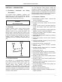
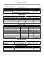
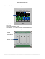
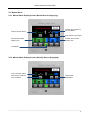
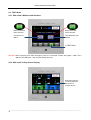
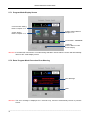
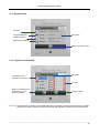
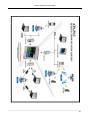
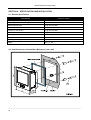
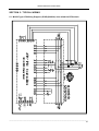
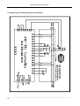
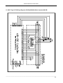
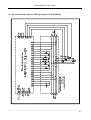
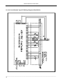
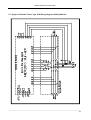
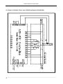
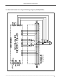
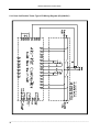
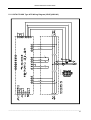
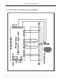
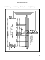
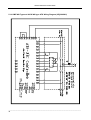
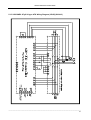
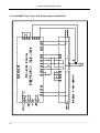
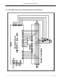
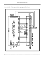
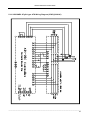
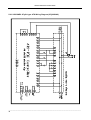
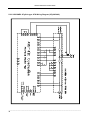
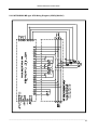
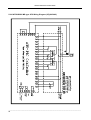
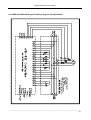
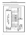
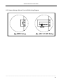
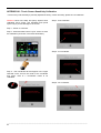
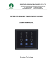
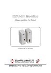
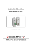
ATS-PLC
Ver1.0
PROGRAMMABLE TOUCH-SCREEN
AUTOMATIC TRANSFER SWITCH
CONTROL UNIT
OPERATOR’S MANUAL
Headquarters : No.3, Lane 201, Chien Fu St., Chyan Jenn Dist., Kaohsiung, TAIWAN
Tel : + 886-7-8121771
Fax : + 886-7-8121775
URL : http://www.kutai.com.tw
ATS-PLC Automatic Transfer Switch
TABLE OF CONTENTS
Section
Page
SECTOIN 1 : INTRODUCTION
1.1 Preliminary Comments and Safety Precautions .............................................................................. 3
1.2 Overview .......................................................................................................................................... 3
1.3 Product Overview ............................................................................................................................. 3
1.4 Functions / Features ........................................................................................................................ 3
1.5 Electrical Characteristics .................................................................................................................. 4
1.6 Exterior Overview ............................................................................................................................. 5
1.7 ATS-PLC quickly start ...................................................................................................................... 6
SECTOIN 2 : TOUCH SCREEN PANEL OVERVIEW
2.1 Status Icons ..................................................................................................................................... 8
2.2 Start-Up Screen ............................................................................................................................... 8
2.3 Auto Mode ........................................................................................................................................ 9
2.4 OFF Mode ...................................................................................................................................... 10
2.5 Manual Mode ................................................................................................................................. 11
2.6 Test Mode ...................................................................................................................................... 12
2.7 Program Mode ............................................................................................................................... 13
SECTOIN 3 : KCU-XX COMMUNICATION MODULE CONFIGURATION
SECTOIN 4 : SPECIFICATION AND INSTALLATION
4.1 General Specification ..................................................................................................................... 26
4.2 Unit Dimension and Installation Reference .................................................................................... 26
SECTION 5 : TYPICAL WIRING
APPENDIX 01: TOUCH SCREEN SENSITIVITY CALIBRATION
APPENDIX 02: DOWNLOAD START-UP SCREEN
______________________________________________________________________________________
2
ATS-PLC Automatic Transfer Switch
SECTION 1 : INTRODUCTION
1.1 Preliminary
Comments
and
Safety
Precautions
The manual covers installation, operation and
maintenance of the ATS-PLC Automatic Transfer
Switch Controller. This manual is for use by
authorized and qualified personnel only.
WARNING
High voltages can kill.
1.2 Overview
Transfer switches protect critical electrical loads
against loss of power. A standby (emergency)
generator backs up the normal grid power. The
transfer switch connects either the normal or the
standby supply to the load. When power is lost from
the grid, the transfer switch transfers the load to the
standby source. Eventually after the grid is
restoration, the ATS connects the load back to the
grid.
The multi parameter setting ranges enables the
controller to operate on all kinds of ATS transfer
Switches and the customizable features to fulfill the
operator’s needs. All configurations are stored in the
internal program memory to prevent loss of data or
important settings during a power outage.
1.4 Functions / Features
● Microcomputer program control, compact size
and easy installation.
● 5.7” inch color LCD touch-screen.
● Program and function setting via touch-screen
operation.
● Voltage, current, frequency and KVA readings for
normal and standby power and current time
display.
● Voltage, current and frequency readings displayed
digitally in numeric or gauge type display.
● Normal and standby power full phase voltage
monitoring and protection.
● Normal and standby power frequency monitoring
and protection.
● Normal and standby reverse phase sequence
protection.
● Normal and standby overload or short circuit trip
monitoring and protection.
● Optional exercise with or without load.
● Optional 1 to 4 weeks automatic scheduled
exercise / testing.
● Pre-alert warning signal output for scheduled
automatic Exercise / testing.
● Transfer failure alarm.
● Full compatibility with all types of ATS switches.
● Optional USB / RS485 / Ethernet remote (mobile
proxy) communication functions.
● Program on-site or from remote (mobile) device
(PC, Smart Phone).
1.3 Product Overview
The ATS-PLC is a programmable multifunction
touch-screen automatic transfer switch control unit
with built in 5.7” inch color touch screen. The
compact design easily replaces the general
conventional ATS controlling circuit board and
controllers. The interface is user friendly with plenty
of preferred settings and configuration to suit user
preference. Suited for single phase/3 phase 3 wires/
3 phase 4 wires systems.
● Program on-site or from remote (mobile) device
(PC, Smart Phone).
● Permanent stored configuration, prevent loss of
data during power outage.
● Front panel display provides source status and
fail alarm indications.
● Built-in 40 sets of event log.
● Built-in 4 digits password protection.
● Multiple language support (Traditional Chinese /
English / Spanish).
______________________________________________________________________________________
3
ATS-PLC Automatic Transfer Switch
1.5 Electrical Characteristics
System Power
ITEM
CONTENT
FACTORY PRESET
System Phase
3 Phase 4 Wires / 3 Phase 3 Wires / Single Phase
3 Phase 3 Wires
Current Transformer (CT)
X/5A (X = Primary Current, 5A = Secondary Ratio)
X = Not Available/50/100/150/200/250/300/400/500/600/800/
1000/1200/1500/1600/2000/3000/4000/5000/6000 (A)
1000/5A
Time Delay Setting
ITEM
SETTING RANGE
UNIT
FACTORY PRESET
Time Delay Emergency to Normal (TDEN)
0 ~ 1800 sec
2 sec/unit
10 sec
Time Delay Normal to Emergency (TDNE)
0 ~ 1800 sec
2 sec/unit
10 sec
Timer Delay Engine Start (TDES)
0 ~ 300 sec
2 sec/unit
10 sec
Timer Delay Engine Cooling (TDEC)
0 ~ 1800 sec
2 sec/unit
30 sec
Time Delay OFF position (TDOF)
0 ~ 300 sec
2 sec/unit
4 sec
Protection Setting
ITEM
SETTING RANGE
UNIT
FACTORY PRESET
110V ~ 530V
10V/unit
250V
-20V ~ 0V
1V/unit
-5V
80V ~ 470V
10V/unit
180V
0V ~ 20V
1V/unit
5V
Normal/ standby Over Frequency Protection
51Hz ~ 75Hz
1Hz/unit
65Hz
Over Frequency Reset Value
-10Hz ~ 0Hz
1Hz/unit
-1Hz
Normal/ standby Under Frequency Protection
40Hz ~ 59Hz
1Hz/unit
55Hz
Under Frequency Reset Value
0Hz ~ 10Hz
1Hz/unit
1Hz
Abnormality Confirmation Time Delay
0 ~ 99 sec
1 sec/unit
10 sec
Reverse Phase Sequence Protection
Enabled / Disabled
Normal/ standby Over Voltage Protection
Over Voltage Reset Value
Normal/ standby Under Voltage Protection
Under Voltage Reset Value
Disabled
Brightness Adjustment
ITEM
Brightness Adjustment
Screen Saver
SETTING RANGE
UNIT
FACTORY PRESET
Level 1 ~ Level 8
1 level
Level 6
2 min ~ 10 min or cancelled
1 minutes
3 min
Communications Transmission
ITEM
SETTING RANGE
FACTORY PRESET
Enable/Disable
Disable
Baudrate
1200 / 2400 / 9600 / 19200 / 38400 / 57600
38400
RS485 Slave Address
00 ~ 99 (Valid value 01 ~ 99;00 Disabled)
00 (Disabled)
Remote Operation
______________________________________________________________________________________
4
ATS-PLC Automatic Transfer Switch
1.6 Exterior Overview
Front
Color Touch-Screen
Power on Indicator
LED (Blinking)
Home Button
Press to return to main page at anytime
Press and hold for 10 sec to execute touch screen sensitivity adjustment function
Rear
Removable DIN
terminals
Terminal Number
Communication
Expansion Sockets
Removable DIN
terminal
Mounting Hole
______________________________________________________________________________________
5
ATS-PLC Automatic Transfer Switch
1.7 ATS-PLC Quickly Start
Step1 : Refer to chapter-5 (wiring diagram) for
completed wiring.
Step5:Select Language. (Refer to 2.7.3.2)
Step2:Turn on the DC power and set the ATS-PLC
controller under OFF mode.
Step6:Setting system phase and CT rated. (Refer
to 2.7.5.1)
Step3:Into programming mode.
Step7:Select switch type. (Refer to 2.7.5.3)
Step4:Setting current time. (Refer to 2.7.3.1)
______________________________________________________________________________________
6
ATS-PLC Automatic Transfer Switch
Step8:Setting exerciser parameter if needed. (Refer
to 2.7.5.4)
Step9:Setting all the necessary protections for both
Normal and Standby source. (Refer to 2.7.5.5)
Step11:Operate testing.
Manually start the genset and transfer the load from
Normal to Standby source by press touch key.
Step12 : Manually transfer the load go back to
Normal Source and stop the genset by press touch
key.
Step10:Power on Normal side AC volt input and set
the ATS-PLC under Manual mode.
Step13:Repeat Step 11 & 12 to make sure the ATS
works or not.
Step14:Set the ATS-PLC on AUTO mode and
finished the quick start procedure.
______________________________________________________________________________________
7
ATS-PLC Automatic Transfer Switch
SECTOIN 2 : TOUCH SCREEN PANEL OVERVIEW
2.1 Status Icons
Icon
Function
Normal power / Grid
Emergency power / Standby
Load
Icon
Function
Engine remote start
TDEN/TDNE/TDEC/TDES
Time delay countdown
Return to last page (Modification will
not be saved if pressed in setting
mode)
Power source connected
Enter / Save
Power source not connected
Increase
Connecting failure
Decrease
Overload or trip warning
Move right
Reverse phase sequence warning
Move left
ATS failure
Event logs erase
Incorrect operation
Mute
Incorrect password entered. System
locked (Please contact with dealer)
2.2 Start-up Screen
Start-up Screen
Displays for 3 sec then
enters operation mode
Press to skip start-up
screen
Attention! Start-up screen is customizable by user, for details please refer to APPENDIX 02.
______________________________________________________________________________________
8
ATS-PLC Automatic Transfer Switch
2.3 Auto Mode
2.3.1 Pointer Gauge Meter Mode Main Screen
Connection Status
Phase Indication (Note 01)
Press to see another phase
Volt / Amp / Hz (Note 02)
Press to change display from
Volt > Amp > Hz
Normal Source Data
Message Area
Normally shows the time
& any Warning when
failure occurs
Pointer Analog Mode
Green = Normal Range
Red = Abnormal Range
Press to change display
mode to digital display
Standby source Data
Programming Buttons
Range In AUTO
【Note 01】3 Phase 3 Wires selection sequence = L12 > L23 > L31.
3 Phase 4 Wires selection sequence = L12 > L23 > L31 > L1N > L2N > L3N
【Note 02】Volt / Amp / Frequency display sequence = Volt > Amp > Hz
2.3.2 Numerical Meter Mode Main Screen
Connection Status
Press to change back to
analog display
Normal Source
Readings
Standby source
Readings
______________________________________________________________________________________
9
ATS-PLC Automatic Transfer Switch
2.4 OFF Mode
2.4.1 OFF Mode Display Screen
Press to Enter Event Log
Current Time
Warning Message
Display Area
Current Date
In “OFF”
From OFF, Press
PROG to Enter System
Programming
2.4.2 Event Log Display Screen
Press to Erase Events
Failure Events Display
Max. Of 40 entries
Time of Failure
Listed in order of occurrence
Move up
Move down
Return to last page
Home Key
Press to Return to OFF Screen
Attention! If controller left untouched or no entries being selected in 60 seconds the screen will automatically
return to OFF screen.
______________________________________________________________________________________
10
ATS-PLC Automatic Transfer Switch
2.5 Manual Mode
2.5.1 Manual Mode Display Screen (Normal Source Supplying)
ATS Connection Status
Standby Source Manual
Connect Button
Engine Start / Stop button
Normal Source Data
Display Area
Standby Source Data
Display Area
In MANUAL
2.5.2 Manual Mode Display Screen (Standby Source Supplying)
ATS Connection Status
Normal Source Manual
Connect Button
Engine Start /
Stop Button
______________________________________________________________________________________
11
ATS-PLC Automatic Transfer Switch
2.6 TEST Mode
2.6.1 With Load / Without Load Selection
Button Illuminates
When Selected
Button Illuminates
When Selected
Test With Load
Botton
Test Without Load
Button
In TEST Mode
Attention! When executing Test while emergency source is connected, system will bypass “ With Load /
Without Load Selection ” and exercise testing with load.
2.6.2 With Load Testing Screen Display
Blue Represents the
Currently Displayed
Parameter for
Standby Source
______________________________________________________________________________________
12
ATS-PLC Automatic Transfer Switch
2.7 Program Mode (PROG)
Attention! Prior to execute system parameter configuration / Programming (PROG), first set system to OFF
Mode then press PROG to enter program configuration, otherwise a operation failure message will
be displayed. (See illustration in 2.7.2 MANU Mode Procedure Error Warning).
Programming Map
System Clock
Chinese
Language
English
Spanish
System Setup
Set New Passcode
Passcode
Change Passcode
Disable Passcode
Set Brightness
Brightness
Screen Saver
En/Dis Communication
Comm. Interface
Baudrate
RS485 Slave Address
Communication
Download Image
System Phase
System Power
CT Setting
TDEN
Program Mode
TDNE
Time Delay
TDES
TDEC
TDOF
MCCB Type (1 Motor)
MOT Type (2 Motors)
Switch Type
ACB Type
Kutai TS Type
Double Throw (1 Coil)
Double Throw (2 Coils)
System Parameter
Exerciser
OV/UV Setting
Normal OV/UV Setting
OV/UV Reset
Time Delay
OF/UF Setting
Normal OF/UF Setting
OF/UF Reset
Time Delay
OV/UV Setting
Protection Setup
Standby OV/UV Setting
OV/UV Reset
Time Delay
OF/UF Setting
Standby OF/UF Setting
OF/UF Reset
Time Delay
Reverse Phase Sequency
Normal V Calibration
Calibrated V/A Reading
Factory Setting
Load A Calibration
Standby V Calibration
______________________________________________________________________________________
13
ATS-PLC Automatic Transfer Switch
2.7.1 Program Mode Display Screen
Communication Setting
Refer to Chapter 2.7.4
System Setting
Refer to Chapter 2.7.3
System Settings Refer to
Chapter 2.7.5
Current Mode“PROGRAM”
Home Key
Press to Return to OFF
Screen Display
Attention! If controller left untouched or no entries being selected in 60 seconds the screen will automatically
return to OFF mode display screen.
2.7.2 Enter Program Mode Procedure Error Warning
Error Message
Mute
Attention! The error message is displayed for 5 seconds only, and then automatically returns to previous
screen.
______________________________________________________________________________________
14
ATS-PLC Automatic Transfer Switch
2.7.3 System Setup
Set Time
Language Selection
Description
Password Setting
Brightness Adjustment
Return to Previous Page
2.7.3.1 System Clock Setting
Decrease
When selected the
background turns blue
Increase
Return to last page button
(Modification are not
saved if pressed)
Enter and Save
Attention! The adjustment of system clock directly affects the automatic exerciser test and event log records,
therefore it is vital to setup the correct current time and date when install the unit for the first time.
______________________________________________________________________________________
15
ATS-PLC Automatic Transfer Switch
2.7.3.2 Language Setting
Currently ATS-PLC operating language only support traditional English and Spanish.
When selected the back
ground turns blue
When selecting the
language it turns blue
2.7.3.3 Passcode Setting
Return to last page
button (Modification are
not saved if pressed)
Correct
Enter and Save
Attention! The Passcode protects only the authority to change or adjust the parameter setting, will not affect
the operation of the controller’s functions.
______________________________________________________________________________________
16
ATS-PLC Automatic Transfer Switch
2.7.3.4 Change or Disable Passcode
Once passcode is set, to change or disable the passcode, enter “System Setup” and click “Passcode”.
Change Passcode
Disable Passcode
2.7.3.5 Brightness Adjustment
Brightness Backlight
adjustment buttons
Brightness Adjustment
Screen Saver time.
When set to maximum, the
screen saver mode will be
cancelled.
______________________________________________________________________________________
17
ATS-PLC Automatic Transfer Switch
2.7.4 Communication Setup
In this setting, user can choose to run the remote communication interface settings and download
personalization of the startup screen function.
Communication Interface
Setting
General Description
Download Startup Screen
Attention! For Startup Screen download program, please refer to Appendix 02.
2.7.4.1 Remote Communication Interface Setting
Enable / Disable
ATS-PLC Remote
Communication
Baud Rate Setting
RS485 Address Setting
______________________________________________________________________________________
18
ATS-PLC Automatic Transfer Switch
2.7.5 System Parameter Setting
System Parameter Setting
General Description
2.7.5.1 System Power Setting
System Power Setting
Phase Selection
CT Setting
Range : 50 ~ 6000 / 5A
______________________________________________________________________________________
19
ATS-PLC Automatic Transfer Switch
2.7.5.2 Time Delay Setting
Current Setting (Red)
Time Delay Setting
Adjustable Rang
(Black)
Attention! All time delay setting is 2 seconds per Unit.
2.7.5.3 Transfer Switch Type Setting
Transfer Switch type
Selection
Transfer Switch
Type Setting
Blue represents the type
selected
Attention! When inconsistent transfer Switch is selected, may cause the ATS fails to operate.
______________________________________________________________________________________
20
ATS-PLC Automatic Transfer Switch
2.7.5.4 Scheduled Automatic Testing / Exerciser Setting
Exerciser Disabled
Attention! When Exerciser is disabled, All corresponding adjustments are omitted.
Exerciser Enabled
Day : 1 = MON, 2 = TUE
Hour : 24hrs
Exercise with / without load
Minutes : 00 to 59
Schedule Interval
Range: 1 to 4 weeks
Exercise Duration : 0 to 120
Unit : Minute
______________________________________________________________________________________
21
ATS-PLC Automatic Transfer Switch
2.7.5.5 Voltage, Frequency Protection and Voltage and Current Reading Adjustment
Normal OV/UV/OF/UF
General Description
Standby OV/UV/OF/UF
Reverse Phase
Voltage and
Current Reading
Adjustment
Voltage and Current Adjustment
Load Current
Adjustment
Normal Source
Voltage Adjustment
Standby Source
Voltage Adjustment
______________________________________________________________________________________
22
ATS-PLC Automatic Transfer Switch
Normal Source Voltage Adjustment
Phase to Phase
Voltage Adjustment
Phase to Neutral
Voltage Adjustment
Attention! This screen is displayed in 3 Phase 4 Wire system voltage setting only.
2.7.5.6 Reset to Factory Setting / Default
Resetting Parameters
to Factory Default
Factory Reset
Confirmation
Attention! When execute factory reset, all modified system parameters will be override to factory preset /
default setting.
______________________________________________________________________________________
23
ATS-PLC Automatic Transfer Switch
SECTION 3 : KCU-XX COMMUNICATION
MODULE SETTING
By installing the KCU-XX modules (EX:KCU-01,
KCU-02, KCU-03.... etc.) to the ATS-PLC, user can
operate or monitor the generator remotely.
The installation for the KCU-XX communication
module on the ATS-PLC controller is fairly simple.
Step 1 : Remove slot cover from the back of
controller.
● KCU-01 – USB communication module
● KCU-02 – RS-485 communications module
● KCU-03 – Ethernet communications module
WARNING
A remote start signal can activate the
ATS-PLC and the engines can start at
anytime without warning. Place a “Danger”
warning sign next to the generator, stating
that this generator can start at anytime!” also
install a warning buzzer or a flash light.
Unexpected engine starts can result in
serious injury or death. When performing
service or maintenance, always disconnect
he remote start signal input.
Step 2 : Insert KCU-XX into the ATS-PLC
communication slot.
WARNING
When servicing or operating near the vicinity
of the generator, Always make sure the
remote communication setting is turned off,
to ensure the safety of the servicing
personnel nearby.
If the KCU-03 Ethernet module installed on the
ATS-PLC you can remotely monitor and operate the
ATS and generator using the IPhone and Android
mobile phones. Free App software is available for
Apple iOS5.1 system or above and android
operating system 2.3.3 or above. Free software can
be downloaded from App Store or Google Play by
simply key in “Kutai” and hit search.
Step 3:Tighten the screw.
For corresponding remote communication settings
please refer to Section 2.7.4.1 and KCU-XX user
manuals and software user manuals.
WARNING
ATS-PLC with KCU-02 module constitutes a
closed LAN network. Each controller address
can be set from 1 to 99 and not to be
repeated. Same transmission rate is a must !!
______________________________________________________________________________________
24
ATS-PLC Automatic Transfer Switch
______________________________________________________________________________________
25
ATS-PLC Automatic Transfer Switch
SECTOIN 4 : SPECIFICATION AND INSTALLATION
4.1 General Specification
PARAMETER
SPECIFICATION
AC Voltage Measurement Range
50 − 530 Vac
Frequency Measurement Range
40 − 75 Hz
Remote Start Contact
7A @ 250 Vac Max
Normal ON Contact
7A @ 250 Vac Max
Emergency ON Contact
7A @ 250 Vac Max
Alarm Output Contact
7A @ 250 Vac Max
Operating Temperature
-20 − +70 °C
Storage Temperature
-30 − +80 °C
Operating Humidity
Maximum 90% relative humidity
Weight
750 g +/- 2%
50/60 Hz
4.2 Unit Dimension and Installation Reference (Unit: mm)
______________________________________________________________________________________
26
ATS-PLC Automatic Transfer Switch
SECTION 5 : TYPICAL WIRING
5.1 MCCB Type ATS Wiring Diagram (3P/4P)(220VAC) also called the BTS switch
______________________________________________________________________________________
27
ATS-PLC Automatic Transfer Switch
5.2 MCCB Type ATS Wiring Diagram (2P)(220VAC)
______________________________________________________________________________________
28
ATS-PLC Automatic Transfer Switch
5.3 MOT Type ATS Wiring Diagram (3P/4P)(220VAC) Motor Operated MCCB
______________________________________________________________________________________
29
ATS-PLC Automatic Transfer Switch
5.4 MOT Type ATS Wiring Diagram (2P)(220VAC)
______________________________________________________________________________________
30
ATS-PLC Automatic Transfer Switch
5.5 Air Circuit Breaker Type ATS Wiring Diagram (3P/4P)(220VAC)
______________________________________________________________________________________
31
ATS-PLC Automatic Transfer Switch
5.6 Air Circuit Breaker Type ATS Wiring Diagram (2P)(220VAC)
______________________________________________________________________________________
32
ATS-PLC Automatic Transfer Switch
5.7 Single Coil Double Throw Type ATS Wiring Diagram (3P/4P)(220VAC)
______________________________________________________________________________________
33
ATS-PLC Automatic Transfer Switch
5.8 Single Coil Double Throw Type ATS Wiring Diagram (2P)(220VAC)
______________________________________________________________________________________
34
ATS-PLC Automatic Transfer Switch
5.9 Dual Coil Double Throw Type ATS Wiring Diagram (3P/4P)(220VAC)
______________________________________________________________________________________
35
ATS-PLC Automatic Transfer Switch
5.10 Dual Coil Double Throw Type ATS Wiring Diagram (2P)(220VAC)
______________________________________________________________________________________
36
ATS-PLC Automatic Transfer Switch
5.11 KUTAI TS-XXX Type ATS Wiring Diagram (3P/4P)(220VAC)
N1
N2
N3
CS1
CS1
CS2
CS2
CS2
BROWN
CN1-1
GREEN
CN1-5
WHITE
CN1-9
BLACK
CN1-10
BLUE
CN1-6
ELS
CS1
NLS
CN1-11
220V
CN1-2
PINK
RED
COIL
CN1-3
CN1 Connector
E1
E2
ORANGE
RED/WHITE
CN1-12
GRAY
CN1-8
YELLOW
CN1-4
E3
______________________________________________________________________________________
37
ATS-PLC Automatic Transfer Switch
5.12 KUTAI TS-XXX Type ATS Wiring Diagram (2P)(220VAC)
N1
N2
CS1
CS2
CS2
BROWN
CN1-1
WHITE
CN1-9
BLACK
CN1-10
BLUE
CN1-6
ELS
CS1
NLS
CN1-11
220V
CN1 Connector
CN1-2
PINK
RED
COIL
CN1-3
E1
ORANGE
RED/WHITE
CN1-12
YELLOW
CN1-4
E2
______________________________________________________________________________________
38
ATS-PLC Automatic Transfer Switch
5.13 KME WN Type and AICHI WN type ATS Wiring Diagram (3P/4P)(220VAC)
______________________________________________________________________________________
39
ATS-PLC Automatic Transfer Switch
5.14 KME WN Type and AICHI WN type ATS Wiring Diagram (2P)(220VAC)
______________________________________________________________________________________
40
ATS-PLC Automatic Transfer Switch
5.15 SOCOMEC ATyS-3S type ATS Wiring Diagram (3P/4P)(220VAC)
______________________________________________________________________________________
41
ATS-PLC Automatic Transfer Switch
5.16 SOCOMEC ATyS-3S type ATS Wiring Diagram (2P)(220VAC)
______________________________________________________________________________________
42
ATS-PLC Automatic Transfer Switch
5.17 SOCOMEC ATyS-3e type ATS Wiring Diagram (3P/4P)(220VAC)
______________________________________________________________________________________
43
ATS-PLC Automatic Transfer Switch
5.18 SOCOMEC ATyS-3e type ATS Wiring Diagram (2P)(220VAC)
______________________________________________________________________________________
44
ATS-PLC Automatic Transfer Switch
5.19 SOCOMEC ATyS-6 type ATS Wiring Diagram (3P/4P)(220VAC)
______________________________________________________________________________________
45
ATS-PLC Automatic Transfer Switch
5.20 SOCOMEC ATyS-6 type ATS Wiring Diagram (2P)(220VAC)
______________________________________________________________________________________
46
ATS-PLC Automatic Transfer Switch
5.21 SOCOMEC ATyS-6e type ATS Wiring Diagram (3P/4P)(220VAC)
______________________________________________________________________________________
47
ATS-PLC Automatic Transfer Switch
5.22 SOCOMEC ATyS-6e type ATS Wiring Diagram (2P)(220VAC)
______________________________________________________________________________________
48
ATS-PLC Automatic Transfer Switch
5.23 MITSUBISHI MD type ATS Wiring Diagram (3P/4P)(220VAC)
______________________________________________________________________________________
49
ATS-PLC Automatic Transfer Switch
5.24 MITSUBISHI MD type ATS Wiring Diagram (2P)(220VAC)
______________________________________________________________________________________
50
ATS-PLC Automatic Transfer Switch
5.25 MERLIN GERIN MCB type ATS Wiring Diagram (3P/4P)(220VAC)
______________________________________________________________________________________
51
ATS-PLC Automatic Transfer Switch
5.26 MERLIN GERIN MCB type ATS Wiring Diagram (2P)(220VAC)
______________________________________________________________________________________
52
ATS-PLC Automatic Transfer Switch
5.27 System Voltage different From AC220V wiring Diagram
______________________________________________________________________________________
53
APPENDIX 01: Touch Screen Sensitivity Calibration
* The accuracy and sensitivity is precisely adjusted in factory, unless necessary, please do not recalibrate.
Attention! Never use sharp and pointy objects when
calibrating touch screen. Use standard touch panel
stylus only to prevent damage to the screen.
Step 4 : 2nd coordinate.
Step 1 : Power on controller.
Step 2 : Press and hold “Home” key for 10secs to enter
the calibration (As shown in the below illustration).
Step 5 : 3rd coordinate.
Step 3 : first coordinate will first appear in the upper
left-hand corner, aim for the center of the coordinate
and press. Total of 7 coordinates needs to be
calibrated
Step 6 : 4th coordinate.
______________________________________________________________________________________
54
ATS-PLC Automatic Transfer Switch
Step 7 : 5th coordinate.
Step 10 : After all 7 coordinates are successfully
calibrated, the screen will display “Saving Calibration
Parameters” to end the sensitivity calibration.
Step 8 : 6th coordinate.
Attention! Once sensitivity calibration begins, all
coordinate must be calibrated, before system is able to
return to normal operation. If accidentally touched the
screen or inaccurate adjustment is made during
calibration, please completed the rest of calibration first
before resuming to step 1 and recalibrate.
Step 9 : 7th coordinate (last calibration).
______________________________________________________________________________________
55
APPENDIX 02:
Download Start-up Screen
When powering up the ATS-PLC, the system will display a customizable start-up screen. This chapter will provide you
with the step by step instruction on how to setup customizing start-up screen.
Note 1 : The Start-up Screen picture format is limited to
bmp, jpg and png files only with image size 630*390.
The system will proportionally reduce the image size if
image size exceeds the limit.
Step 6 : Click on “Link” and select “Connect” to connect
to the KCU-01 module
Note 2 : To download the image from PC to ATS-PLC,
user will need to connect a KCU-01 USB
communication module (optional) to the controller.
KCU-01 USB Module
Step 1 : Before connecting the ATS-PLC to the PC,
user must first install the “KCU-01 Modules” and
“ATS-PLC Image Transfer Software” software to the
PC. Drivers are supplied in the supplied software disk
or can be downloaded from Kutai Electronics website
www.kutai.com.tw.
Step 7 : Select the correct COM Port.
Step 2 : Remove all other communication module(s)
leaving only KCU-01 module installed.
Step 8 : Click “Load Image” and select the image
wishes to upload.
Step 3 : Turn on the DC power.
Step 4 : Connect the USB cable to the KCU-01 and
PC.
Step 5 : Execute the “ATS-PLC Image Transfer
Software”.
______________________________________________________________________________________
56
ATS-PLC Automatic Transfer Switch
Step 9 : Enter Communication Setup and click on
“ATS-PLC Communication Interface”.
Step 10 : Disable ATS-PLC communication function.
Step 11 : Return to Communication Setup and click
“Download Image”.
Step 12 : The controller will display the follow screen.
Step 13 : Click on “Start” on PC screen to begin file
download.
Step 14 : File downloading.
______________________________________________________________________________________
57
Step 15 : Downloading completed.
Step 16 : Click on “OK” to end the downloading
sequence.
Step 17 : Click on “Link” and select “Disconnect” and
remove the USB connection.
Attention! After image is downloaded (Step 15), if user
wishes to change to other image, or download image to
another controller, please remove USB connection
from PC and re-plug it again and retrace back to Step
2.
______________________________________________________________________________________
58