1
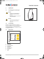
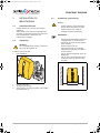
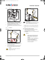
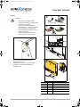
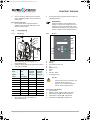
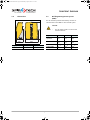
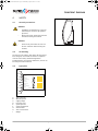
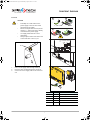
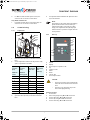
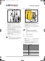
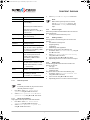
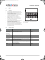
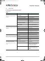
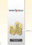
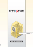
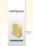
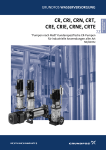
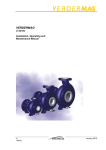
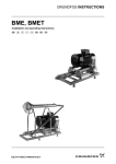
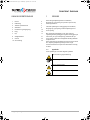
OBJ_BUCH-64-001.book Page 3 Wednesday, April 24, 2013 11:35 AM
SPIROVENT SUPERIOR
INDHOLDSFORTEGNELSE
1
Brugervejledning
Dansk
/i
1
Forord
3
2
Indledning
4
3
Tekniske specifikationer
7
4
Sikkerhed
9
5
Installation og ibrugtagning
10
6
Brug
16
7
Fejl
17
8
Vedligeholdelse
21
9
Garanti
23
10 CE-erklæring
24
FORORD
Denne brugervejledning beskriver installation,
ibrugtagning og betjening af SpiroVent Superior S6A,
S6A-R og S6A-R 2P.
Læs altid vejledningerne omhyggeligt før installation,
ibrugtagning og betjening. Behold vejledningerne til
senere opslag.
Alle rettigheder forbeholdes. Ingen dele af denne
vejledning må mangfoldiggøres og/eller offentliggøres på
Internettet, på tryk, fotokopiering, mikrofilm eller på
nogen anden måde uden forudgående skriftlig tilladelse
fra Spirotech bv.
Denne vejledning er udarbejdet med største omhu. Skulle
der i betjeningsvejledningen alligevel være nogle
uoverensstemmelser kan Spirotech ikke holdes ansvarlig
for disse.
1.1
Symboler
I hele vejledningen anvendes følgende symboler:
Advarsel eller vigtig bemærkning
Bemærkning
Fare for elektrisk stød
Brandfare
Brugervejledning - 2.0
Dansk
3
OBJ_BUCH-64-001.book Page 4 Wednesday, April 24, 2013 11:35 AM
SPIROVENT SUPERIOR
2
INDLEDNING
2.1
Oversigt over enheden
W
V
U
A
T
B
S
C
D
S
R
Superior S6A
E
F
Q
G
P
H
O
I
N
K
M
Superior S6A-R 2P
A
B
C
D
E
F
G
H
I
K
M
N
O
P
4
Automatisk luftudlader
Afluftningsbeholder
Tilgangsslange
Tilslutning til spædning (type S6A-R og S6A-R 2P)
Ventil bag manometer
Skrue
Vandmåler
Niveaukontakt (i bunden af beholderen)
Justerbar tilgangsventil
Reservepumpe (til type S6A-R 2P)
Aftapningstilslutning (under beholderen)
Magnetventil
Hovedpumpe
Justerbar afgangsventil
Superior S6A-R
Q
R
S
T
U
V
W
Dansk
Trykføler
SmartSwitch-bryder
Pressostat
Manometer
Styringsenhed
Afgangsslange
Låg
Brugervejledning - 2.0
OBJ_BUCH-64-001.book Page 5 Wednesday, April 24, 2013 11:35 AM
SPIROVENT SUPERIOR
2.2
Betjening
/i
Nedenstående figur viser betjeningen af enheden i
skemaform. Bogstavangivelserne svarer til
hovedillustrationen på den foregående side.
C
I
PS
R
PI
N
T
A
E
S
PS
B
M
H
LS
P
V
S6A
O
M
S
6
A
R
C
I
PS
P
D
FT
N
PI
A
E
G
S
Q
N
T
PS
B
M
PT
LS
V
S6A-R
H
P
O
M
S
6
A
R
C
I
R
D
FT
M
N
A
G
PS
N
T
E
S
Q
PI
PS
B
M
K
PT
LS
S6A-R 2P
Brugervejledning - 2.0
V
2
P
H
P
O
Dansk
M
5
OBJ_BUCH-64-001.book Page 6 Wednesday, April 24, 2013 11:35 AM
SPIROVENT SUPERIOR
2.2.1
Generelt
SpiroVent er en fuldautomatisk vakuumafgasser til
væskecirkulerende anlæg. Væsker indeholder opløste og
frie gasser. Enheden fjerner disse gasser fra anlægget.
Således elimineres problemer som følge af gasser i
anlægget.
Enheden skal anvendes inden for grænserne af de
tekniske data, der er angivet i dette kapitel 3.
ADVARSEL
•
•
2.2.2
Ekstra pumpe
SpiroVent S6A-R 2P har også en ekstra pumpe. Hvis
hovedpumpen går i stykker, overtager reservepumpen
spædningen fra hovedpumpen
2.4
2.2.3
(Gen)opfyldning
SpiroVent S6A-R og S6A-R 2P har en indbygget
spædningsfunktion.
•
•
•
Spørg altid leverandøren i tvivlstilfælde.
I tilfælde af stærkt forurenet
systemvæske skal der monteres en
snavsudskiller i anlæggets
hovedreturledning.
Leverancen omfatter
1x SpiroVent Superior
1x brugervejledning
1x kontraventil (valgfri)
2.2.4
Afluftning
Enheden starter dagligt afgasningen på et tidspunkt, der
angives af brugeren. Processen har to faser:
1
Stigningsfasen: Væsken løber fra anlægget gennem
magnetventilen (N) til beholderen (B). Pumpen (O)
pumper kontinuerligt den (afgassede) væske fra
beholderen til anlægget. Her absorberer væsken
gasser der findes på anlægget.
2
Vakuumfasen: Magnetventilen (N) lukker med
jævne mellemrum og starter dermed vakuumfasen.
Den kontinuerligt kørende pumpe (O) giver
undertryk i beholderen (B). Med undertrykket
frigives de gasser, der er opløst i væsken, og de
opsamles i toppen af beholderen. De opsamlede
gasser i beholderen fjernes fra anlægget via den
automatiske luftudlader (A). SmartSwitch-bryderen
(R) i styringsenheden sikrer, at afgasningen
standses, så snart indholdet af opløste gasser har
nået et minimumsniveau. Magnetventilen (N) åbner
igen, ved afslutningen af vakuumfasen.
2.2.5
(Gen)opfyldning
En enhed med genopfyldningsfunktionen kan kontrollere
trykket i anlægget. For at kontrollere trykket, tilfører
enheden ekstra afgasset væske, hvis nødvendigt.
Enheden kan også fylde hele anlægget med afgasset
væske.
2.3
Driftsforhold
Enheden er velegnet til brug i systemer fyldt med rent
vand eller blandinger af vand med højst 40% glycol.
Anvendelse sammen med andre væsker kan medføre
uoprettelige skader.
6
Dansk
Brugervejledning - 2.0
OBJ_BUCH-64-001.book Page 7 Wednesday, April 24, 2013 11:35 AM
SPIROVENT SUPERIOR
3
TEKNISKE SPECIFIKATIONER
3.1
Generelle specifikationer
/i
S6A
S6A-R
S6A-R 2P
150 - 300 m
150 - 300 m3
57 kg
59 kg
67 kg
Afgasningsbeholderens volumen
8l
8l
8l
Tilslutning til tilgang
Drejeled G¾” hungev.
Drejeled G¾” hungev.
Drejeled G¾” hungev.
Tilslutning til afgang
Drejeled G¾” hungev.
Drejeled G¾” hungev.
Drejeled G¾” hungev.
Tilslutning til aftapning
Drejeled G¾” hangev.
Drejeled G¾” hangev.
Drejeled G¾” hangev.
Støjniveau
Ca. 57 dB(a)
Ca. 57 dB(a)
Ca. 57 dB(a)
Tilslutning til spædning
Ikke relevant
Drejeled G¾” hungev.
Drejeled G¾” hungev.
Maks. systemvolumen
150 - 300
Tom vægt
3.2
m3
3
Elektriske data
/i
S6A
S6A-R
S6A-R 2P
Forsyningsspænding
230 V ± 10% / 50 eller
60 Hz
230 V ± 10% / 50 eller
60 Hz
230 V ± 10% / 50 eller
60 Hz
Optaget effekt
800 W
800 W
1300 W
Nominelt strømforbrug
3,5 A
3,5 A
5,5 A
Startstrøm
2,6*mærkestrøm
2,6*mærkestrøm
2,6*mærkestrøm
Beskyttelse
10 A / 3,15 A(T)
10 A / 3,15 A(T)
10 A / 3,15 A(T)
Kapslingsklasse
IP X4D
IP X4D
IP X4D
Maks. belastning på
potentialefrie kontakter
24 V / 1 A
24 V / 1 A
24 V / 1 A
Spændingsforsyning til
BMS kontrol
(spænding på BMS)
24 VAC
24 VAC
24 VAC
Forsyningsspænding til
eksternt spædningssignal
(tilført spænding)
Ikke relevant
5 VDC
5 VDC
S6A
S6A-R
S6A-R 2P
Systemtryk
1 - 6 bar
1 - 6 bar
1 - 6 bar
Omgivelsestemperatur °C
0 - 40 °C
0 - 40 °C
0 - 40 °C
Største kompressionstryk
(med lukket ventil bag
manometer)
10 bar
10 bar
10 bar
Opfyldningsflow
Ikke relevant
Se graf i afsnit 6.1
Se graf i afsnit 6.1
Temperatur på
systemvæske
0 - 90 °C
0 - 90 °C
0 - 90 °C
Spædetryk
0 - 6 bar
0 - 6 bar
0 - 6 bar
0 - 70 °C
0 - 70 °C
3.3
Andre data
/i
Temperatur på spædevæske Ikke relevant
Brugervejledning - 2.0
Dansk
7
OBJ_BUCH-64-001.book Page 8 Wednesday, April 24, 2013 11:35 AM
SPIROVENT SUPERIOR
3.4
Mål
3.5
CTS (Building Management System)
Enheden er leveret med hjælpekontakter til
kommunikation med et bygningsautomatiksystem eller
andet eksternt system.
GIV AGT
880
•
Enhedens fejlsignal må ikke bruges som
kedel blokering.
/i
350
590
Signal
S6A
S6A-R
S6A-R 2P
Enhed i
drift
Potentialefrit Potentialefrit Potentialefrit
Fejl på
enhed
Potentialefrit Potentialefrit Potentialefrit
/i
Højde [mm]
Bredde [mm]
Dybde [mm]
880
590
350
8
Frigiv/stop 24 VAC
enhed
24 VAC
24 VAC
Spædning
ved CTS
24 VAC
24 VAC
Dansk
Ikke relevant
Brugervejledning - 2.0
OBJ_BUCH-64-001.book Page 9 Wednesday, April 24, 2013 11:35 AM
SPIROVENT SUPERIOR
4
SIKKERHED
4.1
Grundlæggende forholdsregler
ADVARSEL
•
•
Installationen og vedligeholdelse af
enheden skal udføres af uddannet
personale.
Gør enheden spændings- og trykfri, før
arbejdet påbegyndes.
ADVARSEL
•
4.2
Der er varme dele under låget. Lad
enheden køle ned, før du starter
aktiviteterne.
CE mærkning
Enheden er CE mærket. Det betyder, at enheden er
konstrueret, opbygget og testet i overensstemmelse med
de gældende sikkerheds- og sundhedsbestemmelser.
Hvis brugervejledningen følges, er det sikkert at anvende
og vedligeholde enheden.
4.3
Mærkeplade
A
B
C
D
E
SPIROVENT SUPERIOR
Article-No.:
Type:
Power input:
Voltage / Frequency:
IP class:
Pressure PS:
Temperature TS:
F
Serial no.:
Year of manufacture:
G
Weight:
Spirotech bv - The Netherlands
H
I
A
B
C
D
E
F
G
H
I
Enhedstypen
Optaget effekt
Forsyningsspænding
Kapslingsklasse
Systemtryk
Systemtemperatur
Serienummer
Byggeår
Vægt
Brugervejledning - 2.0
Dansk
9
OBJ_BUCH-64-001.book Page 10 Wednesday, April 24, 2013 11:35 AM
SPIROVENT SUPERIOR
5
INSTALLATION OG
IBRUGTAGNING
5.1
•
•
•
5.3
GIV AGT
Installationsforhold
•
Installer enheden på et frostfrit sted med god
udluftning.
Tilslut enheden til en 230 V/50-60 Hz stikkontakt.
Kontroller, at ekspansionssystemet har de korrekte
mål. Vandvolumenet i enheden kan give
trykvariationer i anlægget.
5.2
•
Installer enheden i overensstemmelse
med de lokale retningslinjer og regler.
Installer enheden som omløb på
anlæggets hovedtransportledning.
BEMÆRKNING
•
Udpakning
ADVARSEL
For at undgå skade på enheden, må den ikke
hejses når den er pakket ud.
•
Enheden leveres på en palle.
1.
Fjern emballagen.
A
Installation og montering
•
B
•
Enheden skal helst installeres på det sted
i anlægskredsen, der har den laveste
temperatur. Her findes de fleste opløste
gasser i væsken.
Installer enheden nær ved
ekspansionssystemet for at mindske
tryksvingninger forårsaget af indløb af
vand af systemet.
Sørg for at betjeningspanelet altid er let
tilgængeligt.
Sørg for at du opretholder den angivne
afstand for service og reparation som
minimum.
•
A C
2.
3.
4.
10
Løsn de 2 skruer (A).
Tag låget (B) af enheden.
Vær to personer om at flytte enheden. Løft enheden
med håndtagene (C).
Dansk
60cm
60cm
Brugervejledning - 2.0
OBJ_BUCH-64-001.book Page 11 Wednesday, April 24, 2013 11:35 AM
SPIROVENT SUPERIOR
5.3.1
Montering
A
A Ø10
D
B
C
E F
G
B Ø10
1.
2.
Vægmontering: Monter enheden på væggen med
hullerne (A). Kontroller, at monteringen kan bære
den fyldte enhed (tom vægt + 10 kg).
Gulvmontering: Placer enheden på et fladt
underlag. Monter enheden på gulvet med hullerne
(B).
5.3.2
BEMÆRKNING
Set fra væskekredsens omløbsretning er første
afgrening tilgangsledningen til enheden.
3.
4.
Installation
Slut ledningen (A) til den fleksible afgangsslange
(D).
Slut ledningen (B) til den fleksible tilgangsslange
(C).
Kun til SpiroVent S6A-R og S6A-R 2P:
1.
Sæt en stopventil (F) og en kontraventil (E) på
indfødningsledningen til spædning.
2.
Slut indfødningsledningen til spædetilslutningen G)
på enheden.
Mekanisk
> 500mm
A
GIV AGT
B
•
A
•
B
•
1.
2.
Benyt en form for kontraventil, der er
lokalt godkendt. En kontraventil kan
bestilles sammen med leveringen af
enheden.
Kontroller, at trykket i spædeledningen
er lavere end systemtrykket. Dette
forhindrer uønsket spædning.
Kontroller, at ledningerne går ud af
enheden på bagsiden.
Lav to afgreninger ¾” (A) på siden af
hovedtransportledningen. Afstanden mellem dem
skal være mindst 500 mm.
Sæt en stopventil (B) på hver afgrening. Dermed
kan enheden gøres trykløs med disse ventiler.
GIV AGT
Kontroller, at stopventilerne er åbne, før
anlægget sættes i drift.
Brugervejledning - 2.0
Dansk
11
OBJ_BUCH-64-001.book Page 12 Wednesday, April 24, 2013 11:35 AM
SPIROVENT SUPERIOR
Elektrisk
1
2
L
GIV AGT
•
•
•
•
Benyt helst en vægstikkontakt til
enhedens strømforsyning. Stikkontakten
skal forblive tilgængelig.
Monter en all-pole hovedafbryder
(kontaktåbning >= 3mm), hvis enheden
sluttes direkte til strømforsyningen.
Anvend strømforsyningskabler med de
korrekte dimensioner.
Udskift altid defekte sikringer med
sikringer af samme værdi. se § 3.2.
PE
N
L1
T >70°C
3
F7 F6 F5 F8 F1
A
J21
J16
J20
F2
J2
1 2
J2 1
0 8
1
6
J1 1
6
1.
2.
3.
Før et 3-delt forbindelseskabel gennem
omdrejningstappen (A).
Indfør kablerne som vist i forbindelsestikket.
Forbind det 3-delte forbindelseskabel til
forbindelsen J16.
4
/i
Stik
Kontakt
Tilslutning
J20
1 og 2
Enheden er klar
3 og 4
Fejl
5 og 6
Tænd/sluk
7 og 8
Spædning1)
1 og 2
Spædning1)
J21
1) gælder for SpiroVent S6A-R og S6A-R 2P.
12
Dansk
Brugervejledning - 2.0
OBJ_BUCH-64-001.book Page 13 Wednesday, April 24, 2013 11:35 AM
SPIROVENT SUPERIOR
4.
5.
Hvis en CTS eller et eksternt system anvendes,
bruges forbindelsesstikket J20 til at tilslutte til
denne enhed.
For SpiroVent S6A-R og S6A-R 2P: Åbn ventilen (G)
på spædeledningen.
BEMÆRKNING
Trykket i beholderen under skyllefasen bør
forøges fra vakuum til overtryk inden for 10
sekunder. Hvis det tager længere tid, så drej
justeringsventilen (B) helt op og derefter til en
position ¼ højere end den faktiske position.
Kun S6A-R og S6A-R 2P:
1.
Hvis en anden ekstern enhed kontrollerer
spædningen, bruges forbindelsesstik J21 til at
tilslutte til denne enhed.
5.4
Ibrugtagning
5.4.1
Klargøring
5.4.2
F
Opstart
E
A
C
B
D
C
A
I
D
H
E
G
F
G
B
1.
2.
Åbn ventilerne (E og F) på tilgangs- og
afgangsledningerne.
Indstil justeringsventilerne fra positionen helt åben?
som angivet i tabellen:
/i
Systemtryk
[bar]
Systemtryk
[bar]
Position,
justeringsventilens
tilgang (B)
Position,
justeringsventilens
afgang (A)
Medie:
Vand
Medie:
Vand/glycol
1-2
-
3
2
2-3
-
2.5
2.5
3-4
-
2.25
6
4-5
-
2
6
5-6
-
1.75
6
-
1-2
6
2
-
2-3
6
2.5
-
3-6
6
6
3.
4.
Åbn ventilen (C) bag manometeret (D).
Åbn ventilerne (E og F) på tilgangs- og
afgangsledningerne.
Brugervejledning - 2.0
A
B
C
D
E
F
G
H
I
Tænd/sluk
Display
Statusrapport i drift / OK
Op
Bekræft / Enter
Menu
Ned
Annuller / Afslut
Statusrapport, fejl
GIV AGT
•
•
Opstartsrutinen starter automatisk, når
enheden tændes første gang.
Tryk på EXIT for at gå et trin tilbage i
menuen under programmering.
Indstil dato og klokkeslæt
1.
Tryk på ON/OFF.
2.
Marker et sprog med S og T. Tryk på ENTER.
3.
Indstil datoen med S og T. Tryk på ENTER.
4.
Indstil dagen med S og T. Tryk på ENTER.
5.
Indstil tiden med S og T. Tryk på ENTER.
Dansk
13
OBJ_BUCH-64-001.book Page 14 Wednesday, April 24, 2013 11:35 AM
SPIROVENT SUPERIOR
5.4.3
Påfyldning af enheden
5.4.4
Kontroller drift
D
C
A
A
B
D
1.
2.
3.
4.
5.
6.
7.
8.
9.
Se § 5.4.1 for instillinger for ventilerne.
Tryk på ENTER to gange. Påfyldningen af enheden
påbegyndes.
Vent i 20 sekunder, til Initial fill busy
forsvinder.
Løsn afluftningsskruen (A) et par omgange og
spænd den til igen, når luften ikke længere kommer
ud.
Gentag trin 1 - 3 indtil vandet begynder at komme
ud af afluftningsskruen ved trin 3.
For Spirovent S6A-R 2P: Gentag trin 1 - 4 for at
udlufte reservepumpen.
Tryk på EXIT to gange. Statusmenuen viser
meddelelsen Err 7, når testen af beskyttelsen
mod at løbe tør er gennemført.
Tryk på MENU. Marker Manual operation med S
og T. Tryk på ENTER.
Marker Reset med S og T. Tryk på ENTER.
1.
2.
3.
4.
BEMÆRKNING
SmartSwitch-bryderen slukker automatisk
for enheden, når koncentrationen af
opløste gasser har nået sit
minimumsniveau.
5.5
Installation og drift
5.5.1
Indstil brugerparametrene
1.
BEMÆRKNING
Den grønne LED lyser for at angive at enheden
er klar til brug. Afgasningen starter som
standard klokken 08:00 dagligt.
Start enheden manuelt, se afsnit 5.5.2.
Kontroller visningen på manometeret (B). Dette skal
skiftevis vise overtryk og undertryk.
Luk ventilen (A) bag manometeret (B).
Sæt låget (C) tilbage på enheden og fastgør den
med de 2 skruer (D).
2.
3.
4.
5.
Tryk på MENU. Marker Settings med S og T.
Tryk på ENTER.
Indstil den parameter, der skal ændres, med S og
T. Tryk på ENTER.
Skift indstillingen med S og T. Tryk på ENTER.
Gentag om nødvendigt trin 2 og 3.
Tryk gentagne gange på EXIT for at vende tilbage til
statusrapporten.
/i
14
Parameter
Beskrivelse
Sprog
Sproget på displayteksterne.
Date
Dags dato.
Ugedag
Den aktuelle ugedag.
Tid
Det aktuelle klokkeslæt.
Autostart 1
Klokkeslæt 1 til start af
afgasningsprocessen.
Autostart 2
Se Auto start 1
Blok.tid dag 1
Klokkeslæt til standsning af
afgasningsprocessen.
Dansk
Brugervejledning - 2.0
OBJ_BUCH-64-001.book Page 15 Wednesday, April 24, 2013 11:35 AM
SPIROVENT SUPERIOR
Parameter
Beskrivelse
Blok.tid dag 2
Se Block.time day 1
Blok.tid uge
Ugedage, hvor enheden ikke skal
fungere.
5.5.3
Påfyldning af anlægget
Gælder kun for SpiroVent S6A-R og S6A-R 2P.
1.
Tryk på MENU. Marker User menu > Manual
operation med S og T. Tryk på ENTER.
2.
Marker Manual operation > system fill
med S og T. Tryk på ENTER.
3.
Marker Degassed eller Non degassed. Tryk på
ENTER.
Valgte dage markeres med et *.
Efter at parametrene er ændret,
vælg Gem med S eller T. Tryk på
ENTER.
Blok.tid aar 1
BEMÆRKNING
Når det ønskede systemtryk er nået, se
Psystem desired i § 5.5.1. Enheden
indtaster standby status og
opfyldningsstop.
Periode pr. år, hvor enheden ikke
skal køre.
Block.time year 2 - 5 Se Block.time year 1.
Max. syst. pressure
Tryk hvor ved enheden stopper
og udsender en alarm.
Max. Systemtryk1)
Det tryk, hvor spædningen
standser. Dette skal sættes så lavt
som muligt, hvis spædningen
styres af CTS
bygningsautomatikken eller
eksterne apparater.
1)
Efterfyldningstryk1)
Det tryk, hvorved spædningen
starter. Dette punkt skal sættes
så lavt som muligt, hvis
spædningen styres af CTS
bygningsautomatikken eller
eksterne apparater.
Efterfyldealarm1)
Maksimal tilladt
spædningsmængde per
spædning. Udsender en alarlm
hvis en spædning overstiger
denne tærskel. (0 - 2500 l; 0 =
slukket).
Efterf.alarm efter1)
Maksimal vedvarende spædetid
(0 - 255 min.; 0 = slukket).
Maks. spædefrekv.1)
Det maksimale antal gange om
dagen at tilspædning er tilladt
(0-10 gange; 0 = slukket).
5.5.5
Aflæse statistikker
Under driften gemmes følgende data i hukommelsen:
•
Akkumulerende driftstimer
•
Afluftningshistorik
•
Fejl historik
•
Genopfyldningshistorik når nødvendigt.
Hukommelsen kan læses således:
1.
Tryk på MENU. Marker User menu > History med
S og T Tryk på ENTER.
2.
Vælg Fejlhistorik eller Drifthistorik med
S og T. Tryk på ENTER.
3.
Marker et punkt med S og T. Tryk på ENTER.
4.
Tryk gentagne gange på EXIT for at vende tilbage til
statusrapporten.
5.5.6
Læsning af data
Følgende overordnede data er lagret i enhedens
hukommelse:
•
Type
•
Softvare version
•
Installationsdato.
De overordnede data kan læses således:
1.
Tryk på MENU. Marker User menu > Generel
info med S og T Tryk på ENTER.
2.
Marker et punkt med S og T. Tryk på ENTER.
3.
Tryk gentagne gange på EXIT for at vende tilbage til
statusrapporten.
1) gælder for SpiroVent S6A-R og S6A-R 2P.
5.5.2
5.5.4
Tænd igen
Følg fremgangsmåden nedenfor, når enheden er slukket.
1.
Udfør proceduren beskrevet i § 5.4.3.
Manuel drift
BEMÆRKNING
Hvis processen afbrydes manuelt, skal den
tændes manuelt igen.
1.
2.
Tryk på MENU. Marker User menu > Manual
operation med S og T. Tryk på ENTER.
Marker Manual operation start eller Manual
operation stop med S og T. Tryk på ENTER.
Brugervejledning - 2.0
Dansk
15
OBJ_BUCH-64-001.book Page 16 Wednesday, April 24, 2013 11:35 AM
SPIROVENT SUPERIOR
6
BRUG
B
6.1
Generelt
Displayet lyser automatiske efter der trykkes på tast.
Displaybelysningen dæmpes automatisk, når der
ikke har været trykket på en tast i 5 minutter.
Hvis enheden er stoppet, forbliver systemet under
overtryk. Sørg for at overtrykket ikke kan beskadige
installationen eller enheden.
Når en pumpe ikke har kørt i 96 timer, køres en
automatisk pumpetest ved førstkommende Auto
start.
Tryk på ON/OFF for at afbryde enheden. Tryk på ON/
OFF for at afbryde enheden igen.
Ved lave væsketemperaturer kan der opstå
kondensering i visse dele. Kondensatet aftappes
gennem åbningerne i rammen.
Gælder kun for SpiroVent S6A-R og S6A-R 2P.
Den væskemængde, der tilspædes (B), afhænger af
forskellen (A) mellem systemtrykket og
spædevandstrykket.
•
•
•
•
•
•
•
6.2
600
500
400
300
200
100
0
0
1
2
3
4
5
A
A
B
Systemtrykket - vandledningstrykket (bar)
Flow (l/t.)
Statusrapporter
/i
Rapport
Beskrivelse
LED-visning
Auto pump test
Enheden kører en pumpetest.
Grøn
End degassing
Stopproceduren kører.
Grøn
Afluftning
Afgasningen kører.
Grøn
Proces stoppet
Enheden er blevet standset manuelt.
Ingen
Standby
Enheden venter på et startsignal.
Grøn
Stoppet af CTS
CTS bygningsautomatikken har standset enheden. Efter frigivning
af CTS skal enheden startes manuelt.
Ingen
Fejl
Enheden er standset på grund af en fejl. Afhjælp fejlen, før
enheden nulstilles, se § 7.4. Enheden er skiftet til en af
ovenstående statusser.
Rød
Enheden tilspæder væske.
Grøn
Anlægget er fyldt op med væske.
Grøn
Afslut påfyldning1)
Afslut systemfyldning1)
Spædning1)
fyldesystem
1)
1) Kun for enheder med påfyldningsfunktion.
16
Dansk
Brugervejledning - 2.0
OBJ_BUCH-64-001.book Page 17 Wednesday, April 24, 2013 11:35 AM
SPIROVENT SUPERIOR
7
FEJL
7.1
Fejlafhjælpning
7.2
ADVARSEL
•
ADVARSEL
•
•
•
Udtagning af drift
I tilfælde af fejl skal installatøren altid
advares.
Gør enheden spændings- og trykfri, før
reparationen påbegyndes. se § 7.2 om
hvordan enheden sættes ud af drift.
Tryk på ON/OFF slukker ikke for
strømmen til enheden.
Sørg for, at det under ingen
omstændigheder er muligt at tilføre
strøm til systemet ved et uheld.
A
B
ADVARSEL
•
Der er varme dele under låget. Lad
enheden køle ned, før du starter
reparationerne.
E
F
C
BEMÆRKNING
D H
•
I tilfælde af fejl lyser den røde LED.
Displayet viser fejlrapporten.
1.
2.
3.
BEMÆRKNING
•
1.
2.
3.
4.
Kun gældende for systemer med
genpåfyldningsindstillingen: Fejlens
alvorlighed bestemmer om enten hele
enheden eller en del af enheden slukker.
Påfyldningsprocessen kan forblive aktiv,
når fejlen er blevet påvist. I sådanne
tilfælde lyser både de røde og grønne
LED'er.
4.
5.
6.
7.
G
Hvis enheden er tændt, tryk på ON/OFF for at stoppe
enheden.
Tag stikket ud af stikkontakten.
Luk ventilerne (A) og/eller (C) i tilgangsledningen og
(B) og/eller (D) i afgangsledningen.
Hvis det er relevant, lukkes ventilen (E) på
spædeledningen også.
Tilslut en aftapningsledning (H) til
aftapningstilslutningen (G).
Tøm enheden med aftapningstilslutningen (G).
Åbn afluftningsskruen på hovedpumpen for at
tømme enheden helt. Se illustrationen i 5.4.2.
Brug en fejlfindingstabel i § 7.3 til at finde årsagen.
Sæt om nødvendigt enheden ud af drift. Se § 7.2.
Afhjælp fejlen.
Nulstil enheden, se § 7.4 eller sæt enheden i drift
igen, se § 5.5.4.
Brugervejledning - 2.0
Dansk
17
OBJ_BUCH-64-001.book Page 18 Wednesday, April 24, 2013 11:35 AM
SPIROVENT SUPERIOR
7.3
Fejlfindingstabel
Bogstavangivelserne svarer til hovedillustrationen i § 2.1.
En oversigt over reservedele findes i afsnit 8.2.
Generelt
Problem
Mulig grund
Afhjælpning
Err 5 Entrance flow
Magnetventilen (N) på tilgangsledningen
åbner ikke.
Udskift (en del i) magnetventilen.
En ventil i tilgangsledningen er lukket.
Åbn ventilen.
Tilgangsledningen er tilstoppet.
Fjern forstoppelsen.
Pressostaten (S) er defekt.
Udskift pressostaten.
Kritisk indstilling af justeringsventilens
tilgang (I).
Drej justeringsventilen ¼ position op
(fra helt åben).
Kablet til trykkontakten (S) er taget af eller
afbrudt.
Udskift kablet. Udskift kabelskoene.
Justeringsventilens (P) tilgang er ikke
placeret rigtigt.
Drej justeringsventilens udgang til
den rigtige stilling (se § 5.4.1 ).
En af magnetventilerne (N) lukker ikke.
Rengør ventilen indvendig. Udskift
om nødvendigt (en del i)
magnetventilen.
En ventil i afgangsledningen er lukket.
Åbn ventilen.
Afgangsledningen er tilstoppet.
Fjern det der blokere
Pumpen (O) kører ikke.
Kontroller pumpen. Kontroller og
udskift pumpens sikring i
styringsenheden.
Pressostaten (S) er defekt.
Udskift pressostaten.
Væskestrømmen i
tilgangsledningen er tilstoppet
1)
.
Err 6 Flow
Gennemstrømningen I
udløbsslangen er blokeret 1).
Den automatiske luftventil (A) er blokeret. Udskift den automatiske luftudlader.
Err 7 Fluid lack vessel
Der er risiko for at køre tør,
væskestanden i beholderen er på
minimum.
Enheden kører kontinuerligt og
slår ikke fra automatisk.
SmartSwitch virker vist ikke1).
Den automatiske luftudlader (A) er defekt
eller tilstoppet.
Udskift den automatiske luftudlader.
Beholderen er ikke blevet fyldt.
Fyld beholderen (Se afsnit 5.5.4).
Niveaukontakten (H) er defekt.
Udskift niveaukontakten.
Kablet til niveaustiften er taget af eller
afbrudt.
Kontroller kabel og udskift når det er
nødvendigt
Indholdet af opløste gasser har endnu
ikke nået minimum.
Kontroller, om der er mulighed for
indtrængende gasser.
SmartSwitch-bryderen (R) er defekt.
Afbryd slangen på den automatiske
luftudladning. Udskift SmartSwitchbryderen, hvis enheden ikke slukker
efter 10 minutter.
Den automatiske luftudlader (A) er defekt. Kontroller, om der slippes gas ud
gennem ventilen. Udskift den
automatiske luftudlader, hvis der ikke
lukkes gas ud.
18
Dansk
Brugervejledning - 2.0
OBJ_BUCH-64-001.book Page 19 Wednesday, April 24, 2013 11:35 AM
SPIROVENT SUPERIOR
Generelt
Problem
Mulig grund
Afhjælpning
Enheden kører i maksimalt 10
min. pr. afgasningsperiode.
Gasserne bliver i anlægget.
SmartSwitch-bryderen (R) er defekt.
Kontroller, om der slippes gas ud
gennem ventilen. Udskift
SmartSwitch-bryderen, hvis der
slipper gas ud.
SmartSwitch virker
tilsyneladende ikke1)
Err 99 Fejl i
kontrolenheden.
Den automatiske luftudlader (A) er defekt. Udskift den automatiske luftudlader.
Kontrolhardware eller -software er defekt. Udskift kontrolenheden.
1) Påfyldningstilstanden forbliver aktiv, kun gældende for systemer med genopfyldningsfunktion.
Kun gældende for systemer med genpåfyldningsindstillingen.
Problem
Mulig grund
Afhjælpning
Err 1 Psystem too low
En fejl i anlægget.
Sørg for et systemtryk på > 1 bar.
Der er en lækage i anlægget.
Reparer lækagen.
Trykføleren (Q) er defekt.
Udskift trykføleren.
Err 2 Psystem too high
En fejl i anlægget.
Sørg for et systemtryk, der ligger
under den indstillede værdi.
Systemtrykket overstiger det
indstillede maksimum.
Den indstillede værdi er for lav.
Forhøj den indstillede værdi.
Trykføleren (Q) er defekt.
Udskift trykføleren.
En ventil i udgangen er lukket.
Åbn ventilen.
Udløbsslangen (T) er blokeret.
Fjern det der blokere
En ventil i spædeledningen er (delvist)
lukket.
Åbn ventilen.
Magnetventilen (N) på
spædeledningen åbner ikke.
Udskift (en del i) magnetventilen.
Spædeledningen er tilstoppet.
Fjern forstoppelsen.
Vandmåleren (G) er defekt.
Udskift vandmåleren.
Magnetventilen (N) på
spædeledningen lukker ikke.
Udskift (en del i) magnetventilen.
Der er en lækage i anlægget.
Reparer lækagen.
Systemtrykket er under 1 bar.
Err 10 Refill flow too low
Der er intet eller kun lille forsyning af
spædevæske1).
Err 11 Refill valve
Utilsigtet tilføring af spædevæske.
Spædningen vil ikke standse.
Err 13 Refill freq. too high
Kontroller indstillingen Max.
refill freq.
Der spædes for ofte.
Err 14 Refill time too high
Der er en lækage i anlægget.
Kontroller indstillingen Alarm
refill after:
Spædningen tager for lang tid.
Err 15 Refill quantity
Reparer lækagen.
Der er en lækage i anlægget.
Reparer lækagen.
Kontroller indstillingen Alarm
refill
Der tilføjes for meget.
1) Spædetilstanden bliver ved at være aktiv
Brugervejledning - 2.0
Dansk
19
OBJ_BUCH-64-001.book Page 20 Wednesday, April 24, 2013 11:35 AM
SPIROVENT SUPERIOR
7.4
1.
2.
20
Nulstilling af enheden
Tryk på MENU. Marker User menu > Manual
operation med S og T. Tryk på ENTER.
Marker Manual operation reset med S og T.
Tryk på ENTER.
Dansk
Brugervejledning - 2.0
OBJ_BUCH-64-001.book Page 21 Wednesday, April 24, 2013 11:35 AM
SPIROVENT SUPERIOR
8
VEDLIGEHOLDELSE
8.1
Periodisk vedligeholdelse
1.
2.
BEMÆRKNING
Udskift magnetventilens indvendige dele årligt (N).
Udskift den automatiske luftventilering hvert andet
år.
8.2
•
Korrekt og regelmæssig vedligeholdelse
vil sikre enhedens korrekte funktion og
maksimere levetiden samt problemfri
drift af enheden og systemet.
Regelmæssige analyser af systemvæske
vil hjælpe til rette forholdsregler for
fastholdelse af korrekt væskekvalitet og
deraf følgende systemydelse.
Reservedele
Bogstavangivelserne svarer til hovedillustrationen i 2.1.
Del nummer
Bogstav
/i
Beskrivelse
15.552
O
Akselpakning til pumpe type CR1-13/1-9 AAA HQQE
15.553
O
Pakningssæt til pumpetype CR1-9 og CR1-13
15.554
O
Kondensator til pumpetype CR1-13
15.790
O
Kondensator til pumpetype CR1-9
15.510
O
Pumpetype CR1-13 AAA HQQE (50 Hz)
15.511
O
Pumpetype CR1-9 AAA HQQE (60 Hz)
R70,675
W
Låg
12.023
N
Magnetventil (ekskl. spole)
12.022
N
Spole til magnetventil
15.765
N
Indvendige dele til magnetventil
12.021
T
Manometer
R17,889
-
Kontraventil til spædning
R17,886
A
Automatisk luftudlader
13.468
S
Pressostat
R18.091A05
U
Kontrolenhed (S6A)
R18.091A06
U
Kontrolenhed (S6A-R)
R18.091A07
U
Kontrolenhed (S6A-R 2P)
R17,888
R
SmartSwitch-bryder
15.518
I
Justeringsventil
13.466
H
Niveaukontakt
15.519
G
Vandmåler (S6A-R og S6A-R 2P)
15.520
Q
Trykmåler (S6A-R og S6A-R 2P)
15.521
K
Pumpetype PSAM70/A (S6A-R 2P) (50 Hz)
15.522
K
Pumpetype PSAM706/A (S6A-R 2P) (60 Hz)
Brugervejledning - 2.0
Dansk
21
OBJ_BUCH-64-001.book Page 22 Wednesday, April 24, 2013 11:35 AM
SPIROVENT SUPERIOR
8.3
Vedligeholdelseskort
/i
Type:
Serienummer:
Installationsdato.
Installeret af firmaet:
Installeret af tekniker:
Inspektionsdato:
Tekniker:
Initialer:
Tekniker:
Initialer:
Tekniker:
Initialer:
Tekniker:
Initialer:
Tekniker:
Initialer:
Tekniker:
Initialer:
Vedligeholdelsesart:
Inspektionsdato:
Vedligeholdelsesart:
Inspektionsdato:
Vedligeholdelsesart:
Inspektionsdato:
Vedligeholdelsesart:
Inspektionsdato:
Vedligeholdelsesart:
Inspektionsdato:
Vedligeholdelsesart:
22
Dansk
Brugervejledning - 2.0
OBJ_BUCH-64-001.book Page 23 Wednesday, April 24, 2013 11:35 AM
SPIROVENT SUPERIOR
9
GARANTI
9.1
Garantibetingelser
•
•
•
Garantien for Spirotech produkter er gyldig i 2 år
efter købsdatoen.
Garantien bortfalder i tilfælde af fejlinstallation,
inkompetent brug og/eller reparationsforsøg af
ikke-autoriserede personer.
Følgeskader dækkes ikke af garantien.
Brugervejledning - 2.0
Dansk
23
OBJ_BUCH-64-001.book Page 24 Wednesday, April 24, 2013 11:35 AM
SPIROVENT SUPERIOR
10
CE-ERKLÆRING
10.1
Overensstemmelseserklæring
/i
24
Dansk
Brugervejledning - 2.0
OBJ_BUCH-64-001.book Page 25 Wednesday, April 24, 2013 11:35 AM
SPIROVENT SUPERIOR
TABLE OF CONTENTS
1
User manual
English
/i
1
Preface
25
2
Introduction
26
3
Technical specifications
29
4
Safety
31
5
Installation and commissioning
32
6
Use
38
7
Failures
39
8
Maintenance
43
9
Guarantee
45
10 CE statement
46
PREFACE
This user manual describes the installation,
commissioning and operation of the SpiroVent Superior
S6A, S6A-R and S6A-R 2P.
Read the instructions before installation, commissioning
and operation. Keep the instructions for future reference.
All rights reserved. No part of this manual may be
duplicated and/or made public through the Internet, by
means of printing, photocopying, microfilm or in any
other way without prior written permission from
Spirotech bv.
This manual has been composed with the utmost care.
Should, however, this manual contain any inaccuracies,
Spirotech bv cannot be held responsible for this.
1.1
Symbols
Throughout the instructions the following symbols are
used:
Warning or important note
Note
Risk of electric shock
Risk of burning
User manual - 2.0
English
25
OBJ_BUCH-64-001.book Page 26 Wednesday, April 24, 2013 11:35 AM
SPIROVENT SUPERIOR
2
INTRODUCTION
2.1
Overview of the unit
W
V
U
A
T
B
S
C
D
S
R
Superior S6A
E
F
Q
G
P
H
O
I
N
K
M
Superior S6A-R 2P
A
B
C
D
E
F
G
H
I
K
M
N
O
P
26
Automatic air vent
Deaeration vessel
Inlet hose
Refill connection (types S6A-R and S6A-R 2P)
Valve behind pressure gauge
Screw
Water flow meter
Level switch (in bottom of vessel)
Adjustable inlet valve
Back-up pump (for type S6A-R 2P)
Drain connection (under the vessel)
Solenoid valve
Main pump
Adjustable outlet valve
Superior S6A-R
Q
R
S
T
U
V
W
English
Pressure sensor
SmartSwitch
Pressure switch
Pressure gauge
Control unit
Outlet hose
Cover
User manual - 2.0
OBJ_BUCH-64-001.book Page 27 Wednesday, April 24, 2013 11:35 AM
SPIROVENT SUPERIOR
2.2
Operation
/i
The figure below schematically shows the operation of
the unit. The letter indications correspond with the main
figure on the previous page.
C
I
PS
R
PI
N
T
A
E
S
PS
B
M
H
LS
V
S6A
P
O
M
S
6
A
R
C
I
PS
P
D
FT
N
PI
A
E
G
S
Q
N
T
PS
B
M
PT
LS
V
S6A-R
H
P
O
M
S
6
A
R
C
I
R
D
FT
M
N
A
G
PS
N
T
E
S
Q
PI
PS
B
M
K
PT
LS
S6A-R 2P
User manual - 2.0
V
2
P
H
P
O
English
M
27
OBJ_BUCH-64-001.book Page 28 Wednesday, April 24, 2013 11:35 AM
SPIROVENT SUPERIOR
2.2.1
General
The SpiroVent is a fully automatic vacuum degasser for
installations filled with fluid. Fluids contain dissolved and
free gases. The unit removes these gases from the
installation. Problems caused by gases in the installation
are thus prevented.
The unit should be used within the limits of the technical
specifications as given in chapter 3.
WARNING
•
2.2.2
Back-up pump
The SpiroVent S6A-R 2P also has a back-up pump. In case
of a break-down of the main pump, the back-up pump
takes over the refill function of the main pump.
2.2.3
(Re)fill
The SpiroVent S6A-R and S6A-R 2P have integrated refill
functionality.
•
2.4
•
•
•
In case of doubt, always contact the
supplier.
In case of a heavily contaminated system
fluid, a dirt separator is to be installed in
the main return line of the installation.
Scope of delivery
1x SpiroVent Superior
1x User manual
1x Non-return protection (optional)
2.2.4
Degassing
The unit starts up daily a degassing process at a time set
by the user. The process has two phases:
1
The rinsing phase: The fluid flows from the
installation through the solenoid valve (N) into the
vessel (B). The pump (O) continuously pumps the
fluid from the vessel into the installation. Here the
fluid absorbs gases present in the installation.
2
The vacuum phase: The solenoid valve (N) regularly
closes, starting a vacuum phase. The continuously
running pump (O) provides underpressure in the
vessel (B). The underpressure causes the release of
the gases dissolved in the fluid, which are collected
at the top of the vessel. The gases are removed
from the installation through the automatic air vent
(A). The SmartSwitch (R) in the control unit makes
sure that the degassing is stopped as soon as the
content of dissolved gases has reached the
minimum level. The solenoid valve (N) opens again,
at the end of the vacuum phase.
2.2.5
(Re)filling
A unit with the refill functionality can control the
pressure of the installation. To control the pressure the
unit insert additional degassed fluid, if necessary. The
unit can also fill the entire installation with degassed
fluid.
2.3
Operating conditions
The unit is suitable for use in systems filled with clean
water or mixtures of water with a maximum of 40%
glycol. Use in combination with other fluids may result in
irreparable damage.
28
English
User manual - 2.0
OBJ_BUCH-64-001.book Page 29 Wednesday, April 24, 2013 11:35 AM
SPIROVENT SUPERIOR
3
TECHNICAL SPECIFICATIONS
3.1
General specifications
/i
S6A
S6A-R
S6A-R 2P
150 - 300 m
150 - 300 m3
57 kg
59 kg
67 kg
Volume of degassing vessel
8l
8l
8l
Inlet connection
Swivel G¾” f.t.
Swivel G¾” f.t.
Swivel G¾” f.t.
Outlet connection
Swivel G¾” f.t.
Swivel G¾” f.t.
Swivel G¾” f.t.
Drain connection
Swivel G¾” m.t.
Swivel G¾” m.t.
Swivel G¾” m.t.
Noise level
Approx. 57 dB(a)
Approx. 57 dB(a)
Approx. 57 dB(a)
Refill connection
n/a
Swivel G¾” f.t.
Swivel G¾” f.t.
S6A
S6A-R
S6A-R 2P
Supply voltage
230 V ± 10% / 50 or 60 Hz
230 V ± 10% / 50 or 60 Hz
230 V ± 10% / 50 or 60 Hz
Absorbed power
800 W
800 W
1300 W
Nominal power
consumption
3.5 A
3.5 A
5.5 A
Starting current
2.6*nominal current
2.6*nominal current
2.6*nominal current
Protection
10 A / 3.15 A(T)
10 A / 3.15 A(T)
10 A / 3.15 A(T)
Protection class
IP X4D
IP X4D
IP X4D
Max. load of potential-free
contacts
24 V / 1 A
24 V / 1 A
24 V / 1 A
Supply voltage for BMS
control
(voltage of BMS)
24 Vac
24 Vac
24 Vac
Supply voltage of external
refill signal
(supplied voltage)
n/a
5 Vdc
5 Vdc
S6A
S6A-R
S6A-R 2P
System pressure
1 - 6 bar
1 - 6 bar
1 - 6 bar
Ambient temperature
0 - 40 °C
0 - 40 °C
0 - 40 °C
Maximum compression
pressure (with closed valve
behind pressure gauge)
10 bar
10 bar
10 bar
Refill flow
n/a
See graph in § 6.1
See graph in § 6.1
System fluid temperature
0 - 90 °C.
0 - 90 °C
0 - 90 °C
Refill pressure
0 - 6 bar
0 - 6 bar
0 - 6 bar
Refill fluid temperature
n/a
0 - 70 °C
0 - 70 °C
Max. system volume
150 - 300
Empty weight
3.2
m3
3
Electrical specifications
/i
3.3
Other specifications
/i
User manual - 2.0
English
29
OBJ_BUCH-64-001.book Page 30 Wednesday, April 24, 2013 11:35 AM
SPIROVENT SUPERIOR
3.4
Dimensions
3.5
Building Management System
(BMS)
The unit has been provided with auxiliary contacts for
communication with a BMS or other external system.
CAUTION
880
•
The unit failure signal is not to be used
as boiler interlock.
/i
350
590
Signal
S6A
S6A-R
S6A-R 2P
Unit in
operation
Potential
free
Potential
free
Potential
free
Unit failure
Potential
free
Potential
free
Potential
free
Unit release/stop 24 Vac
24 Vac
24 Vac
Refill by BMS
24 Vac
24 Vac
/i
Height [mm]
Width [mm]
Depth [mm]
880
590
350
30
English
n/a
User manual - 2.0
OBJ_BUCH-64-001.book Page 31 Wednesday, April 24, 2013 11:35 AM
SPIROVENT SUPERIOR
4
SAFETY
4.1
General precautions
WARNING
•
•
Installation and maintenance of the unit
should only be carried out by qualified
personnel.
Remove the power and pressure from the
unit before starting the activities.
WARNING
•
4.2
There are hot parts under the cover. Let
the unit cool down before starting the
activities.
CE marking
The unit has a CE marking. This means that the unit has
been designed, constructed and tested in compliance
with the current safety and health regulations.
Provided that the user manual is adhered to, the unit can
be safely used and maintained.
4.3
Type plate
A
B
C
D
E
SPIROVENT SUPERIOR
Article-No.:
Type:
Power input:
Voltage / Frequency:
IP class:
Pressure PS:
Temperature TS:
F
Serial no.:
Year of manufacture:
G
Weight:
Spirotech bv - The Netherlands
H
I
A
B
C
D
E
F
G
H
I
Type of the unit
Absorbed power
Supply voltage
Protection class
System pressure
System temperature
Serial number
Year of construction
Weight
User manual - 2.0
English
31
OBJ_BUCH-64-001.book Page 32 Wednesday, April 24, 2013 11:35 AM
SPIROVENT SUPERIOR
5
INSTALLATION AND
COMMISSIONING
5.1
•
•
•
5.3
CAUTION
Installation conditions
•
Install the unit on a frost-free, well-ventilated place.
Connect the unit to a 230 V / 50 -60 Hz supply.
Make sure that the expansion system has the
proper dimensions. The water displacement in the
unit can cause pressure variations in the
installation.
5.2
•
WARNING
To prevent damage to the unit do not hoist
the unpacked unit.
•
The unit is delivered on a pallet.
1.
Remove the packaging.
•
B
Install the unit in accordance with the
local guidelines and rules.
Install the unit as bypass on the main
line of the installation.
NOTE
•
Unpack
A
Installation and mounting
•
Preferably install the unit at the point in
the installation with the lowest
temperature. Here the most dissolved
gases are found in the fluid.
Install the unit close to the expansion
system to minimise pressure fluctuations
caused by the intake of water by the
system.
Make sure that the operating panel is
always easily accessible.
Make sure that you maintain at least the
distance for service and repair as
indicated.
•
A C
2.
3.
4.
32
Loosen the 2 screws (A).
Remove the cover (B) from the unit.
Move the unit with two persons. Lift the unit using
the handles (C).
English
60cm
60cm
User manual - 2.0
OBJ_BUCH-64-001.book Page 33 Wednesday, April 24, 2013 11:35 AM
SPIROVENT SUPERIOR
5.3.1
Mounting
A
A Ø10
D
B
C
E F
G
B Ø10
1.
2.
Wall mounting: Mount the unit on the wall using
the holes (A). Make sure that the mounting can
support the filled unit (empty weight ± 10 kg).
Floor mounting: Place the unit on a flat surface.
Mount the unit on the floor using the holes (B).
5.3.2
NOTE
As seen from the direction of the volume flow,
the first branch is the inlet into the unit.
3.
4.
Connect the line (A) to the flexible outlet hose (D).
Connect the line (B) to the flexible inlet hose (C).
Only for SpiroVent S6A-R and S6A-R 2P:
1.
Insert a valve (F) and a non-return protection (E) in
the refill fluid supply line.
2.
Connect the supply line to the refill connection (G)
of the unit.
Installation
Mechanical
> 500mm
A
CAUTION
B
•
A
•
B
•
1.
2.
Use a locally approved non-return
protection. A non-return protection can
also be supplied as an option with the
unit.
Make sure that the pressure in the water
lines is below the system pressure. This
prevents undesired refilling.
Make sure that the lines leave the unit at
the rear.
Make two branch lines ¾” (A) on the side of the
main transport line. The distance between them
should be at least 500 mm.
Insert a valve (B) in each branch. With these valves
the unit can be depressurised.
CAUTION
Make sure that the valves are opened before
putting the unit into operation.
User manual - 2.0
English
33
OBJ_BUCH-64-001.book Page 34 Wednesday, April 24, 2013 11:35 AM
SPIROVENT SUPERIOR
Electrical
1
2
L
CAUTION
•
•
•
•
Preferably use a wall socket for the
power supply to the unit. The socket
should remain accessible.
Mount an all-pole main switch (contact
opening >= 3mm) if the unit is directly
connected to the power supply.
Use supply cables with the correct
dimensions.
Always replace a defect fuse with a fuse
of the same value. refer to § 3.2.
PE
N
L1
T >70°C
3
F7 F6 F5 F8 F1
A
J21
J16
J20
F2
J2
1 2
J2 1
0 8
1
6
J1 1
6
1.
2.
3.
Feed a 3-core supply cable through swivel (A).
Insert the wires as indicated into the connector.
Connect the 3-core supply cable to the connector
J16.
4
/i
connector
contact
connection
J20
1 and 2
Unit ready
3 and 4
Failure
5 and 6
On/off
7 and 8
Refill1)
1 and 2
Refill1)
J21
1) applies to SpiroVent S6A-R and S6A-R 2P.
34
English
User manual - 2.0
OBJ_BUCH-64-001.book Page 35 Wednesday, April 24, 2013 11:35 AM
SPIROVENT SUPERIOR
4.
5.
If a BMS or other external system is used, use
connector J20 to connect to that device.
For SpiroVent S6A-R and S6A-R 2P: Open the valve
(G) in the refill line.
Only S6A-R and S6A-R 2P:
1.
If another external device controls the refill, use
connector J21 to connect to that device.
5.4
Commissioning
5.4.1
Preparation
NOTE
The pressure in the vessel during the flushing
phase should increase from vacuum up to
overpressure within 10 seconds. If it takes
longer, turn adjustment valve (B) fully open
and then back to a position¼ higher than the
actual position.
5.4.2
E
F
Start up
C
A
D
B
C
A
G
B
1.
2.
Close the valves (E and F) in the inlet and outlet
lines.
Set the adjustment valves from the position “fully
open” as specified in the table:
/i
System
pressure
[bar]
System
pressure
[bar]
Position
adjustment
valve inlet
(B)
Position
adjustment
valve
outlet (A)
Medium:
water
Medium:
water/glycol
1-2
-
3
2
2-3
-
2.5
2.5
3-4
-
2.25
6
4-5
-
2
6
5-6
-
1.75
6
-
1-2
6
2
-
2-3
6
2.5
-
3-6
6
6
3.
4.
D
H
E
G
F
On/off
Display
Status report in operation / OK
Up
Confirm / Enter
Menu
Down
Cancel / Exit
Status report failure
CAUTION
•
•
Open the valve (C) behind the pressure gauge (D).
Open the valves (E and F) in the inlet and outlet
lines.
User manual - 2.0
A
B
C
D
E
F
G
H
I
I
The start-up routine starts automatically
when the unit is switched on for the first
time.
Press EXIT to go back one step in the
menu while programming.
Set date and time
1.
Press ON/OFF.
2.
Select a language using S and T. Press ENTER.
3.
Set the date using S and T. Press ENTER.
4.
Set the day using S and T. Press ENTER.
5.
Set the time using S and T. Press ENTER.
English
35
OBJ_BUCH-64-001.book Page 36 Wednesday, April 24, 2013 11:35 AM
SPIROVENT SUPERIOR
5.4.3
5.4.4
Filling the unit
Check operation
D
C
A
A
B
D
1.
2.
3.
4.
5.
6.
7.
8.
9.
Refer to § 5.4.1 for the settings of the valves.
Press ENTER two times. The unit starts filling.
Wait for 20 seconds until Initial fill busy
disappears.
Loosen the air vent screw (A) a few turns and
tighten it again when air has stopped coming out.
Repeat steps 1 - 3 until water starts coming out of
the air vent screw at step 3.
For Spirovent S6A-R 2P: Repeat steps 1 - 4 to
deaerate the back-up pump.
Press EXIT two times. The status menu shows the
message Err 7 when the test of the run dry
protection has been completed successfully.
Press MENU. Select Manual operation using S
and T. Press ENTER.
Select Reset using S and T. Press ENTER.
NOTE
When the green LED is lit this indicates that
the unit is ready for use. Degassing starts by
default every day at 08:00 hours.
1.
2.
3.
4.
Manually start the unit, see § 5.5.2.
Check the indication of the pressure gauge (B). This
should alternately display overpressure and
underpressure.
Close the valve (A) behind the pressure gauge (B).
Put back the cover (C) on the unit and fasten it with
the 2 screws (D).
NOTE
The SmartSwitch will automatically turn
off the unit when the concentration of
dissolved gases has reached the minimum
level.
5.5
Install and operate
5.5.1
Set the user parameters
1.
2.
3.
4.
5.
Press MENU. Select Settings using S and T. Press
ENTER.
Select the parameter to be changed using S and
T. Press ENTER.
Change the setting using S and T. Press ENTER.
Repeat steps 2 and 3, if necessary.
Repeatedly press EXIT to return to the status report.
/i
36
Parameter
Description
Language
Language for the display texts.
Date
The current date.
Weekday
The current weekday.
Time
The current time.
Auto start 1
Time 1 for starting the degassing
process.
Auto start 2
See Auto start 1.
Block.time day 1
Time for stopping the degassing
process.
English
User manual - 2.0
OBJ_BUCH-64-001.book Page 37 Wednesday, April 24, 2013 11:35 AM
SPIROVENT SUPERIOR
3.
Parameter
Description
Block.time day 2
See Block.time day 1.
Block.time week
Days of the week on which the unit
is not working.
NOTE
When desired system pressure is reached,
refer to Psystem desired in § 5.5.1. The
unit enters the standby status and filling
stops.
Selected days are marked with an *.
After having changed this
parameter, select Save using S or
T. Press ENTER.
5.5.4
Switch on again
Follow the procedure described below after the unit has
been switched off.
1.
Do the procedure described in § 5.4.3.
Block.time year 1
Period per year during which the
unit is not working.
Block.time year 2
-5
See Block.time year 1.
Max. syst.
pressure 1)
Pressure at which the unit stops
and flags an alarm.
Psystem desired1)
Pressure at which the refilling
stops. Set this as low as possible if
the refilling is controlled by a BMS
or an external devices.
Refillpressure1)
Pressure at which the refilling
starts. Set this point as low as
possible when the refilling is
controlled by a BMS or other
external device.
Refill alarm1)
Maximum allowed refill quantity
per refill. Issues an alarm if a refill
exceeds this threshold. (0 - 2500 l;
0 = switched off).
Refill alarm
after1)
Maximum continuous refill time (0 255 min.; 0 = switched off).
Max. refill freq.1)
Maximum number of times per day
that refilling is allowed
(0 - 10 times; 0 = switched off).
5.5.5
Reading statistics
During operation the following data are stored in the
memory:
•
Accumulative running hours
•
Degassing history
•
Fault history
•
Refill history when applicable.
The memory can be read in the following way:
1.
Press MENU. Select User menu > History using S
and T. Press ENTER.
2.
Select Fault history or Operation history
using S and T. Press ENTER.
3.
Select an item using S and T. Press ENTER.
4.
Repeatedly press EXIT to return to the status report.
1) applies to the SpiroVent S6A-R and S6A-R 2P.
5.5.2
Select Degassed or Not degassed. Press ENTER.
5.5.6
Reading data
The following general data have been stored in the
memory of the unit:
•
Unit type
•
Software version
•
Installation date.
The general data can be read in the following way:
1.
Press MENU. Select User menu > General info
using S and T. Press ENTER.
2.
Select an item using S and T. Press ENTER.
3.
Repeatedly press EXIT to return to the status report.
Manual operation
NOTE
If manually switched off, the process must be
manually switched on again.
1.
2.
Press MENU. Select User menu > Manual
operation using S and T. Press ENTER.
Select Manual operation start or Manual
operation stop using S and T. Press ENTER.
5.5.3
Filling the installation
Only applies to the SpiroVent S6A-R and S6A-R 2P.
1.
Press MENU. Select User menu > Manual
operation using S and T. Press ENTER.
2.
Select Manual operation > system fill
using S and T. Press ENTER.
User manual - 2.0
English
37
OBJ_BUCH-64-001.book Page 38 Wednesday, April 24, 2013 11:35 AM
SPIROVENT SUPERIOR
6
USE
B
6.1
General
The display lights automatically after a key press.
The display lighting automatically dims after no key
has been pressed for 5 minutes.
Is the unit is stopped, the system remains under
overpressure. Make sure that the overpressure can
not damage the installation or the unit.
When a pump has not run for 96 hours, an
automatic pump test is run at the first next Auto
start.
Press ON/OFF to switch off the unit. Press ON/OFF
again to switch on the unit again.
At low fluid temperatures condensation may occur
at certain parts. The condensation is drained
through the openings in the frame.
Applies only to the SpiroVent S6A-R and S6A-R 2P:
The amount of fluid that is added (B) depends on
the difference (A) between the system pressure and
the refill water pressure.
•
•
•
•
•
•
•
6.2
600
500
400
300
200
100
0
0
1
2
3
4
5
A
A
B
System pressure - water pipe pressure (bar)
Flow (l/hour)
Status reports
/i
Report
Description
LED indication
Auto pump test
The unit runs a pump test.
Green
End degassing
The stop procedure is in process.
Green
Degassing
The degassing process is in process.
Green
Process stopped
The unit has been stopped manually.
None
Standby
The unit is waiting for a starting signal.
Green
Stop by BMS
The BMS has stopped the unit. After release by the BMS the
unit must be started manually.
None
Failure
The unit has stopped because of a failure. Remedy the failure
before resetting the unit, see § 7.4. The unit is switched to one
of the above statuses.
Red
The unit is refilling fluid.
Green
The installation is filled with fluid.
Green
End refilling1)
End systemfill1)
Refill1)
fill system
1)
1) Only for the units with the refill functionality.
38
English
User manual - 2.0
OBJ_BUCH-64-001.book Page 39 Wednesday, April 24, 2013 11:35 AM
SPIROVENT SUPERIOR
7
FAILURES
7.1
Remedy failures
7.2
WARNING
•
WARNING
•
•
•
Putting out of operation
In case of a failure always warn the
installer.
Remove the power and pressure from
the unit before starting repairs. refer to
§ 7.2 on how to put the unit out of
operation.
Pressing ON/OFF does not remove the
power from the unit.
Make sure that under no circumstance it
is possible to unintentionally supply
power to the system.
A
B
WARNING
•
There are hot parts under the cover. Let
the unit cool down before starting
repairs.
E
F
C
NOTE
•
D H
In case of a failure the red LED is lit. The
display shows the failure report.
2.
3.
NOTE
•
1.
2.
3.
4.
1.
Only applicable to systems with the refill
option: The seriousness of the failure
determines whether the whole unit or a
part of the unit switches off. The refill
process can remain active when a failure
has been detected. In this case both the
red and the green LEDs are lit.
4.
5.
6.
7.
G
If the unit is switched on Press ON/OFF to stop the
unit.
Take the plug out of the wall socket.
Close the valves (A) and/or (C) in the inlet line and
(B) and/or (D) in the outlet line.
Close, if applicable, the valve (E) in the refill supply
line (F) as well.
Connect a drain line (H) to the drain connection (G).
Drain the unit through the drain connection (G).
Open the air vent screw on the main pump to
completely empty the unit. See the figure in §
5.4.2.
Use the failure table in § 7.3 to localise the cause.
If necessary, put the unit out of operation. Refer to
§ 7.2.
Remedy the failure.
Reset the unit, refer to § 7.4 or put the unit into
operation again, see § 5.5.4.
User manual - 2.0
English
39
OBJ_BUCH-64-001.book Page 40 Wednesday, April 24, 2013 11:35 AM
SPIROVENT SUPERIOR
7.3
Failure table
The letter indications correspond with the main figure in
§ 2.1. An overview of the replacement parts has been
included in § 8.2.
General
Problem
Possible cause
Correction
Err 5 Entrance flow
The solenoid valve (N) in the inlet line
does not open.
Replace (a part of) the solenoid valve.
A valve in the inlet line is closed.
Open the valve.
The inlet line has been blocked.
Remove the blocking.
The pressure switch (S) is defect.
Replace the pressure switch.
Critical setting adjustment valve inlet
(I).
Turn adjustment valve ¼ position up
(from fully open).
Cable to pressure switch (S)
disconnected or interrupted.
Replace the cable. Replace the cable
lugs.
The adjustment valve (P) inlet has not
been set correctly.
Turn the adjustment valve outlet to
the correct position (see § 5.4.1).
One of the solenoid valves (N) is not
closing.
Clean valve internally. If necessary,
replace (a part of) the solenoid valve.
The valve in the outlet line is closed.
Open the valve.
The outlet line has been blocked.
Remove the obstruction.
The pump (O) does not run.
Check the pump. Check and replace
the pump fuse in the control unit.
The pressure switch (S) is defect.
Replace the pressure switch.
The automatic air vent (A) is blocked.
Replace the automatic air vent.
The automatic air vent (A) is defect or
blocked.
Replace the automatic air vent.
The vessel has not been filled.
Fill the vessel (see § 5.5.4).
The level switch (H) is defect.
Replace the level switch.
Cable to level pin disconnected or
interrupted.
Check cable and replace when
necessary
The content of dissolved gases has
not reached the minimum yet.
Check whether there is a possibility of
gases entering.
The SmartSwitch (R) is defect.
Disconnect the hose on the
automatic air vent. Replace the
SmartSwitch if the unit does not
switch off after 10 minutes.
The automatic air vent (A) is defect.
Check whether gas is released
through the valve. Replace the
automatic air vent when no gas is
released.
The flow in the inlet line has been
blocked 1).
Err 6 Flow
The flow in the outlet line has been
blocked 1).
Err 7 Fluid lack vessel
There is a risk of running dry, the fluid
level in the vessel is at the minimum.
The unit runs continuously and does
not switch off automatically.
The SmartSwitch does not seem to
work1).
40
English
User manual - 2.0
OBJ_BUCH-64-001.book Page 41 Wednesday, April 24, 2013 11:35 AM
SPIROVENT SUPERIOR
General
Problem
Possible cause
Correction
The unit runs maximal 10 min. per
degassing period. Gases remain in
the installation.
The SmartSwitch (R) is defect.
Check whether gas is released
through the valve. Replace the
SmartSwitch if gas is released.
The automatic air vent (A) is defect.
Replace the automatic air vent.
Control hardware or software is
defect.
Replace the control unit.
The SmartSwitch does not seem to
work1)
Err 99 Failure in the
control unit.
1) The refill mode remains active, only applicable for the systems with the refill functionality.
Only applicable to the systems with the refill functionality.
Problem
Possible cause
Correction
Err 1 Psystem too low
A failure in the installation.
Provide a system pressure of > 1 bar.
There is a leak in the installation.
Repair the leak.
The pressure sensor (Q) is defect.
Replace the pressure sensor.
Err 2 Psystem too high
A failure in the installation.
Provide a system pressure that is
below the set value.
The system pressure exceeds the set
maximum.
The set value is too low.
Increase the set value.
The pressure sensor (Q) is defect.
Replace the pressure sensor.
A valve in the outlet is closed.
Open the valve.
The outlet line (T) has been
obstructed.
Remove the obstruction.
A valve in the refill line is (partly)
closed.
Open the valve.
The solenoid valve (N) in the refill line
does not open.
Replace (a part of) the solenoid valve.
The refill line has been blocked.
Remove the blocking.
The water flow meter (G) is defect.
Replace the water flow meter.
The solenoid valve (N) in the refill line
does not close.
Replace (a part of) the solenoid valve.
There is a leak in the installation.
Repair the leak.
The system pressure is below 1 bar.
Err 10 Refill flow too low
There is no or little supply of refill
fluid1).
Err 11 Refill valve
Undesired supply of refill fluid. The
refilling does not stop.
Err 13 Refill freq. too high
Check the setting Max. refill
freq.
Refilling takes place too frequently.
Err 14 Refill time too high
There is a leak in the installation.
Check the setting Alarm refill
after:
Refilling takes too long.
Err 15 Refill quantity
Repair the leak.
There is a leak in the installation.
Repair the leak.
Check the setting Alarm refill.
Too much is added.
1) The refill mode remains active
User manual - 2.0
English
41
OBJ_BUCH-64-001.book Page 42 Wednesday, April 24, 2013 11:35 AM
SPIROVENT SUPERIOR
7.4
1.
2.
42
Resetting the unit
Press MENU. Select User menu > Manual
operation using S and T. Press ENTER.
Select Manual operation reset using S and
T. Press ENTER.
English
User manual - 2.0
OBJ_BUCH-64-001.book Page 43 Wednesday, April 24, 2013 11:35 AM
SPIROVENT SUPERIOR
8
MAINTENANCE
8.1
Periodic maintenance
1.
2.
NOTE
Annually replace the interior of the solenoid valves
(N).
Replace the automatic air vent every two years.
8.2
•
Proper and regular maintenance will
ensure correct functioning of the unit
and maximize the life time expectancy
as well as a trouble free operation of the
unit and system. Regular analyses of the
system fluid will help to take the right
measures to maintain the correct fluid
quality and consequently system
performance.
Replacement parts
The letter indications comply with the main figure in
§ 2.1.
Article number
Letter
/i
Description
15.552
O
Shaft sealing for pump type CR1-13/1-9 AAA HQQE
15.553
O
Gasket set for pump type CR1-9 and CR1-13
15.554
O
Capacitor for pump type CR1-13
15.790
O
Capacitor for pump type CR1-9
15.510
O
Pump type CR1-13 AAA HQQE (50 Hz)
15.511
O
Pump type CR1-9 AAA HQQE (60 Hz)
R70.675
W
Cover
12.023
N
Solenoid valve (excluding coil)
12.022
N
Coil for solenoid valve
15.765
N
Interior for solenoid valve
12.021
T
Pressure gauge
R17.889
-
Non-return valve refill
R17.886
A
Automatic air vent
13.468
S
Pressure switch
R18.091A05
U
Control unit (S6A)
R18.091A06
U
Control unit (S6A-R)
R18.091A07
U
Control unit (S6A-R 2P)
R17.888
R
SmartSwitch
15.518
I
Adjustment valve
13.466
H
Level switch
15.519
G
Water flow meter (S6A-R and S6A-R 2P)
15.520
Q
Pressure sensor (S6A-R and S6A-R 2P)
15.521
K
Pump type PSAM70/A (S6A-R 2P) (50 Hz)
15.522
K
Pump type PSAM706/A (S6A-R 2P) (60 Hz)
User manual - 2.0
English
43
OBJ_BUCH-64-001.book Page 44 Wednesday, April 24, 2013 11:35 AM
SPIROVENT SUPERIOR
8.3
Maintenance card
/i
Type:
Serial number:
Installation date:
Installed by firm:
Installed by technician:
Inspection date:
Technician:
Initials:
Technician:
Initials:
Technician:
Initials:
Technician:
Initials:
Technician:
Initials:
Technician:
Initials:
Nature of the maintenance:
Inspection date:
Nature of the maintenance:
Inspection date:
Nature of the maintenance:
Inspection date:
Nature of the maintenance:
Inspection date:
Nature of the maintenance:
Inspection date:
Nature of the maintenance:
44
English
User manual - 2.0
OBJ_BUCH-64-001.book Page 45 Wednesday, April 24, 2013 11:35 AM
SPIROVENT SUPERIOR
9
GUARANTEE
9.1
Terms of guarantee
•
•
•
The guarantee for Spirotech products is valid until 2
years following the purchasing date.
The guarantee lapses in cases of faulty installation,
incompetent use and/or non-authorised personnel
trying to make repairs.
Consequential damage is not covered by the
guarantee.
User manual - 2.0
English
45
OBJ_BUCH-64-001.book Page 46 Wednesday, April 24, 2013 11:35 AM
SPIROVENT SUPERIOR
10
CE STATEMENT
10.1
Declaration of conformity
/i
46
English
User manual - 2.0