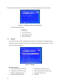
1
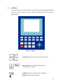
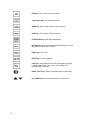
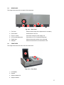
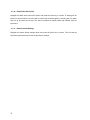
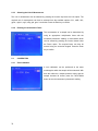
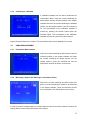
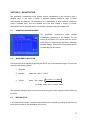
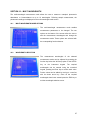
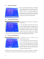
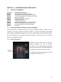
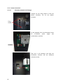
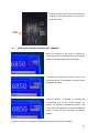
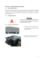
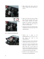
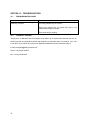
6850 Spectrophotometer Operating Manual 685 030 REV A/03-12 Safety Please read this information carefully prior to installing or using this equipment. 1. The unit described in this manual is designed to be operated only by trained personnel. Any adjustments, maintenance and repair must be carried out as defined in this manual, by a person qualified to be aware of the hazards involved. 2. It is essential that both operating and service personnel employ a safe system of work, in addition to the detailed instructions specified in this manual. 3. Other than for those items defined in the maintenance procedures herein there are no user serviceable items in this instrument. Removal of covers and attempted adjustment or service by unqualified personnel will invalidate the warranty and may incur additional charges for repair. 4. References should always be made to the Health and Safety data supplied with any chemicals used. Generally accepted laboratory procedures for safe handling of chemicals should be employed. 5. If it is suspected that safety protection has been impaired in any way, the unit must be made inoperative and secured against any intended operation. The fault condition should immediately be reported to the appropriate servicing authority. Merci de lire attentivement ces informations avant d'installer ou d'utiliser cet appareil. 1. L'appareil décrit dans ce manuel est conçu pour être utilisé uniquement par des personnes formées. Tout réglage, maintenance ou réparation doit être effectué comme décrit dans ce manuel, par une personne qualifiée consciente des risques encourus. 2. Il est essentiel que les personnes utilisant et intervenant sur cet appareil respectent les règles de sécurité de travail, en plus des instructions détaillées précisées dans ce manuel. 3. En-dehors des éléments décrits dans les procédures de maintenance ci-incluses, cet appareil ne contient aucun élément réparable par l'utilisateur. L'enlèvement des capots et les tentatives de réglage ou de réparation par des personnes non qualifiées invalide toute garantie et entraîne un risque de frais de réparation supplémentaires. 4. Toujours se référer aux fiches techniques de santé et de sécurité accompagnant tout produit chimique utilisé. Respecter les procédures de laboratoire généralement acceptées pour la manipulation en toute sécurité des produits chimiques. 5. Si l'utilisateur suspecte qu'un problème quelconque puisse mettre en cause la sécurité, l’appareil doit être rendu inopérant en empêchant son utilisation. Communiquer la défaillance constatée au service de maintenance compétent. 2 Bitte lesen Sie diese Hinweise vor Installation oder Gebrauch dieser Ausrüstung sorgfältig durch. 1. Das in diesem Handbuch beschriebene Gerät darf nur von geschultem Personal bedient werden. Alle Anpassungen, Wartungsarbeiten und Reparaturen müssen entsprechend der Vorgaben in diesem Handbuch und von einer kompetenten Person, die mit den damit verbundenen Gefahren vertraut ist, durchgeführt werden. 2. Es ist wichtig, dass sowohl das Bedienungs- als auch das Service-Personal zusätzlich zu den detaillierten Anweisungen in diesem Handbuch ein sicheres Arbeitssystem einsetzen. 3. Mit Ausnahme der Teile, deren Wartungsverfahren in diesem Handbuch beschrieben sind, enthält dieses Gerät keine weiteren Teile, die vom Benutzer gewartet werden können. Das Entfernen von Abdeckungen und Versuche von hierfür unqualifiziertem Personal, Anpassungen oder Wartungsarbeiten durchzuführen, haben zur Folge, dass die Garantie verfällt und können zusätzliche Reparaturkosten auslösen. 4. Es ist jederzeit auf die sicherheitsrelevanten Daten sämtlicher verwendeter Chemikalien Bezug zu nehmen. Allgemein anerkannte Labormethoden zum sicheren Umgang mit Chemikalien sollten eingesetzt werden. 5. Besteht der Verdacht, dass die Sicherheitsvorrichtungen in irgendeiner Weise beschädigt wurden, muss das Gerät außer Betrieb genommen und gegen weiteren Gebrauch gesichert werden. Die Störung sollte der zuständigen Serviceeinrichtung unverzüglich gemeldet werden. Leggere attentamente queste istruzioni prima di installare o utilizzare il dispositivo. 1. L'unità descritta nel presente manuale è stata realizzata per essere utilizzata solo da personale che ha ricevuto l'apposita formazione. Qualsiasi operazione di regolazione, manutenzione e riparazione deve essere effettuata sulla base di quanto indicato nel presente manuale da personale qualificato consapevole dei rischi connessi. 2. È fondamentale che il personale operativo e il personale addetto alla manutenzione utilizzino un sistema di lavoro sicuro, oltre a seguire le istruzioni specificate nel presente manuale. 3. Oltre a quelli indicati nelle procedure di manutenzione, all'interno di questo dispositivo non sono presenti altri elementi sui quali è possibile effettuare interventi. La rimozione delle protezioni e qualsiasi tentativo di regolazione o di manutenzione posto in essere da personale non qualificato invaliderà la garanzia. In questi casi, sarà necessario pagare un importo per le riparazioni effettuate. 3 4. È sempre necessario fare riferimento ai dati sulla salute e sulla sicurezza forniti con le sostanze chimiche utilizzate. Adottare le procedure di laboratorio generalmente accettate per la gestione delle sostanze chimiche. 5. Nel caso in cui si sospetti che la salute possa essere pregiudicata in qualsiasi modo, disattivare l'unità per renderla inutilizzabile. Qualsiasi condizione di errore deve essere immediatamente segnalata al responsabile per la manutenzione. Lea esta información atentamente antes de instalar o utilizar este equipo. 1. La unidad descrita en este manual está diseñada para que solamente la utilice personal con formación. Cualquier operación de ajuste, mantenimiento y reparación debe llevarse a cabo del modo indicado en este manual y debe realizarla una persona cualificada que sea consciente de los peligros que implica. 2. Es fundamental que tanto los operarios como el personal de servicio utilicen un sistema de trabajo seguro, así como las instrucciones detalladas que se especifican en este manual. 3. Cualquier elemento que no se encuentre entre los definidos en los procedimientos de mantenimiento aquí descritos no podrá utilizarse en este instrumento. La extracción de las tapas y los intentos de ajuste o reparación por parte de personal no cualificado invalidarán la garantía y pueden incurrir en cargos adicionales por reparación. 4. Siempre deberían consultarse los datos sobre Salud y Seguridad que se suministran con cualquier producto químico que se utilice. Es necesario llevar a cabo los procedimientos de laboratorio de aceptación generalizada para la manipulación segura de productos químicos. 5. Si existe la sospecha de que las medidas protectoras de seguridad han quedado dañadas en cualquier modo, la unidad debe inutilizarse y protegerse contra toda operación que se intente llevar a cabo. El estado de fallo debe comunicarse inmediatamente a la autoridad de servicio de mantenimiento y reparación pertinente. 4 Contents SECTION 1 – Introduction ....................................................................................... 8 1.1 1.2 INSTRUMENT DESCRIPTION............................................................................................. 8 INSTRUMENT SPECIFICATION ......................................................................................... 8 SECTION 2 – Installation ......................................................................................... 9 2.1 2.2 2.3 2.4 2.5 2.6 UNPACKING ........................................................................................................................ 9 INSTALLATION .................................................................................................................... 9 DISPLAY ............................................................................................................................. 10 CONTROLS ........................................................................................................................ 11 REAR PANEL ..................................................................................................................... 13 FRONT VIEW ..................................................................................................................... 13 SECTION 3 – THEORY AND PRACTICE OF SPECTROSCOPY MEASUREMENTS..... 14 3.1 3.2 3.3 3.4 THEORY OF SPECTROSCOPY MEASUREMENT .......................................................... 14 NUCLEIC ACID DETERMINATION ................................................................................... 15 SPECTROSCOPY MEASUREMENT ................................................................................. 15 GOOD PRACTICE GUIDELINES ....................................................................................... 16 SECTION 4 – INSTRUMENT SETUP ...................................................................... 18 4.1 4.2 4.2.1 4.3 4.3.1 4.3.2 4.3.3 4.3.3.1 4.3.4 4.3.4.1 4.3.4.2 4.3.4.3 4.3.5 4.3.6 4.3.7 4.3.8 4.3.9 4.3.10 4.3.11 INSTRUMENT NAVIGATION ............................................................................................. 18 MAIN MENU SCREEN ....................................................................................................... 18 Slit Width Setting ................................................................................................................ 18 SYSTEM UTILITY MENU ................................................................................................... 19 Wavelength Reset .............................................................................................................. 19 Printer Setup ....................................................................................................................... 19 Lamp Setup ........................................................................................................................ 20 Change the Lamp Switch Point.................................................................................. 20 Clock Setup ........................................................................................................................ 20 Set Time ..................................................................................................................... 20 Set Date ..................................................................................................................... 21 Display Time / Date .................................................................................................... 21 Refresh Dark Current.......................................................................................................... 21 Connect to PC .................................................................................................................... 21 Beeper On/Off ..................................................................................................................... 21 Language Selection ............................................................................................................ 21 Refresh System Baseline ................................................................................................... 21 Delete Entire Saved Files ................................................................................................... 22 Restore Default Settings ..................................................................................................... 22 SECTION 5 – PHOTOMETRICS.............................................................................. 23 5.1 5.2 5.2.1 5.2.2 5.2.3 5.2.4 5.3 5.3.1 5.3.2 5.4 PHOTOMETRICS MENU SCREEN ................................................................................... 23 METHOD SET UP .............................................................................................................. 23 Selecting a Wavelength ...................................................................................................... 23 Selecting the Measurement Mode ...................................................................................... 23 Selecting the Unit of Measurement .................................................................................... 24 Entering a Concentration Factor ......................................................................................... 24 CALIBRATION .................................................................................................................... 24 Zero Calibration .................................................................................................................. 24 Calibrating to a Standard .................................................................................................... 25 SAMPLE MEASUREMENT ................................................................................................ 25 5 5.4.1 5.4.2 5.4.3 Photometric Measurements ................................................................................................ 25 Measuring a Sample after Entering a Concentration Factor .............................................. 25 Measuring a Sample after Calibrating to a Standard ......................................................... 26 SECTION 6 – QUANTITATION ............................................................................... 27 6.1 6.2 6.3 6.3.1 6.3.2 6.3.2.1 6.3.2.2 6.3.2.3 6.3.2.4 6.4 6.5 6.6 6.7 6.7.1 6.8 6.9 QUANTITATION MODE SCREEN ..................................................................................... 27 WAVELENGTH SELECTION ............................................................................................. 27 METHOD SETUP ............................................................................................................... 27 Selecting the Unit of Measurement .................................................................................... 28 Quantitation Table Settings ................................................................................................ 28 Select Curve Fit.......................................................................................................... 28 Manually Enter Curve Constants ............................................................................... 29 Edit Calibration Table ................................................................................................. 29 Display Calibration Curve .......................................................................................... 29 CREATING A NEW STANDARD CURVE .......................................................................... 30 STORING A STANDARD CURVE ..................................................................................... 31 RECALLING A STORED STANDARD CURVE ................................................................. 31 SAMPLE MEASUREMENTS .............................................................................................. 31 Quantitation Measurements................................................................................................ 32 STORING RESULTS .......................................................................................................... 32 RECALLING STORED RESULTS ...................................................................................... 32 SECTION 7 – SPECTRUM ...................................................................................... 33 7.1 7.2 7.3 7.4 7.5 7.6 7.7 7.8 7.9 SPECTRUM MODE SCREEN ............................................................................................ 33 METHOD SETUP ............................................................................................................... 33 SELECTING THE MEASUREMENT MODE ...................................................................... 34 SAMPLE MEASUREMENTS .............................................................................................. 34 ADJUSTING THE DISPLAYED SCAN RANGE ................................................................. 34 SPECTRUM SEARCH........................................................................................................ 35 SPECTRUM SMOOTHING ................................................................................................ 35 STORING RESULTS .......................................................................................................... 35 RECALLING STORED RESULTS ...................................................................................... 36 SECTION 8 – KINETICS.......................................................................................... 37 8.1 8.2 8.3 8.3.1 8.4 8.5 8.6 8.7 8.8 8.9 KINETICS MODE SCREEN ............................................................................................... 37 WAVELENGTH SELECTION ............................................................................................. 37 METHOD SETUP ............................................................................................................... 37 Selecting the Measurement Mode ...................................................................................... 38 SAMPLE MEASUREMENTS .............................................................................................. 38 ADJUSTING THE DISPLAYED SCAN RANGE ................................................................. 38 CALCULATING I/U CONCENTRATION ............................................................................ 39 SPECTRUM SMOOTHING ................................................................................................ 39 STORING RESULTS .......................................................................................................... 40 RECALLING STORED RESULTS ...................................................................................... 40 SECTION 9 – DNA/PROTEIN .................................................................................. 41 9.1 9.2 9.3 9.4 9.5 9.6 9.7 9.8 6 DNA MENU OPTIONS ....................................................................................................... 41 ADJUSTING THE MEASUREMENT MODE ...................................................................... 41 WAVELENGTH SELECTION ............................................................................................. 42 ADJUSTING THE CONCENTRATION CALCULATION FACTORS .................................. 42 SELECTING THE UNIT OF MEASUREMENT................................................................... 42 RESET MODE SETTINGS ................................................................................................. 43 DNA/PROTEIN MEASUREMENTS .................................................................................... 43 STORING METHODS/RESULTS ....................................................................................... 43 9.9 RECALLING STORED RESULTS ...................................................................................... 44 SECTION 10 – MULTI-WAVELENGTH ................................................................... 45 10.1 10.2 10.3 10.4 10.5 MULTI-WAVELENGTH MODE OPTIONS ......................................................................... 45 WAVELENGTH SELECTION ............................................................................................. 45 SAMPLE MEASUREMENT ................................................................................................ 46 STORING METHODS/RESULTS ....................................................................................... 46 RECALLING STORED RESULTS ...................................................................................... 46 SECTION 11 – ACCESSORIES AND SPARE PARTS ........................................... 47 11.1 OPTIONAL ACCESSORIES............................................................................................... 47 11.2 INSTALLING THE PASSIVE AND ACTIVE ACCESSORIES ............................................ 47 11.2.1 Passive Accessories ........................................................................................................... 47 11.2.2 Active Accessories.............................................................................................................. 48 11.2.2.1 8 Position Automatic Cell Changer ............................................................................ 48 11.3 USING THE 8 POSITON AUTOMATIC CELL CHANGER ................................................ 49 11.4 SPARES ............................................................................................................................. 50 SECTION 12 – MAINTENANCE AND SETVICE ..................................................... 51 12.1 12.2 12.2.1 12.2.2 12.3 ROUTINE MAINTENANCE ................................................................................................ 51 LAMP REPLACEMENT ...................................................................................................... 51 Tungsten Lamp Replacement ............................................................................................ 51 Deuterium Lamp Replacement ........................................................................................... 52 SERVICE ............................................................................................................................ 53 SECTION 13 – TROUBLESHOOTING .................................................................... 54 13.1 13.2 TROUBLESHOOTING GUIDE ........................................................................................... 54 TECHNICAL SUPPORT ..................................................................................................... 54 SECTION 14 – DECLARATION OF CONFORMITY ............................................... 55 7 SECTION 1 – Introduction 1.1 INSTRUMENT DESCRIPTION The 6850 is a variable bandwidth, double beam UV/visible spectrophotometer with an integrated user interface for local control. This instrument has highly stable optics and two detectors that measure the sample and reference solutions simultaneously to optimise the accuracy of the measurement. The 6850 has measurement modes for photometrics, concentration, multi-wavelength, spectrum scanning, quantitation, kinetics and DNA and Protein analysis. The instrument is supplied with Jenway Prism PC software to allow full PC control of the spectrophotometer. 1.2 INSTRUMENT SPECIFICATION 6850 Wavelength Range Resolution Accuracy Repeatability Spectral bandwidth Photometrics Transmittance Absorbance Accuracy Reproducibility Resolution Stray light Noise Stability Quantitation Range Data points Calibration Units Curve fit algorithms Multi-wavelength Range Data points Kinetics Measurement Time Scan Interval Calibration Display Analysis Spectrum Range Scan speed Scan interval DNA Measurement modes 8 190 to 1100nm 0.1nm ± 0.3nm (at 0.5 and 1nm bandwidth) ± 0.5nm (at 2, 4 and 5nm bandwidth) ± 0.2nm Variable 0.5 / 1 / 2 / 4 and 5nm 0 to 200% -0.3 to 3.0A ±0.3%T (0 – 100%T), ±0.002A (0 – 0.5A) ±0.001 Abs (0 to 0.5 Abs) ±0.002 Abs (0.5 to 1.0 Abs) 0.1%T, 0.001A <0.05% at 360nm and 220nm 0.0005A ±0.001A at 500nm after 15min warm up 0 to 99999 Up to 3 wavelengths Blank with up to 10 standards IU, mM/L, M/L, μg/mL, mg/mL, mg/L, mEq, ppb, ppm, % and other Linear, Linear through zero, Quadratic and Cubic 0 to 99999 Up to 10 wavelengths Up to 12 hours 0.1, 0.2, 0.5, 1, 2, 5, 10 or 30 seconds Blank with a single standard or factor Graphical and concentration Slope and line of best fit between any two points Any range between 190 to 1100nm 100 to 2000nm/min Selectable 0.1, 0.2, 0.5, 1, 2 or 5nm DNA/RNA Ratio, concentration, A320 correction Protein Measurement modes Other Beam height Light source Outputs Power Size (w x d x h) Weight Direct UV 15mm Tungsten and Deuterium lamps USB, Parallel (Printer) 110/220V AC 50/60Hz 600 x 450 x 260mm 22kg SECTION 2 – Installation 2.1 UNPACKING Remove the 6850 from the packaging and ensure the following items are included: 1. Model 6850 spectrophotometer fitted with 10 x 10mm cuvette holder (685-SC) 2. Power supply cables HH179(S) – UK lead HH180(S) – EU lead CABLEUS – US lead 3. Instruction manual (685 030) 4. 10mm Glass Cuvettes x 4 (035 027) 5. 10mm Quartz Cuvettes x 2 (035 028) 6. Dust Cover (685 040) 7. PC software CD and USB security dongle (685 035) 2.2 INSTALLATION The 6850 is supplied ready to use. The working temperature and humidity range of the 6850 spectrophotometer is 15 – 35˚C, 15 – 70% relative humidity. The storage temperature and humidity range of the 6850 spectrophotometer is -10 – 50˚C, 15 – 70% relative humidity. The unit should be placed on a clean flat surface which is free from drafts and vibrations. The units are designed for operation on 110V±11V / 60Hz±1Hz and 220V±22V / 50Hz±1Hz AC. Connect the power supply unit to the power inlet socket on the rear panel of the instrument and connect to the mains socket. Turn the power on at the mains and switch the instrument on using the power switch on the rear of the instrument. 9 The instrument will initially perform several power-on tests before displaying the warm up screen: Fig 2.2.1 – Instrument power-on tests complete The power-on tests comprise 1. Lamp test 2. Detector test 3. A to D converter test 4. Grating position check 5. Dark current check 2.3 DISPLAY The instrument has an inclusive display which enables text and graphs to be displayed clearly. Following successful completion of the power-on tests and the instrument warm up time, the main menu screen will be displayed: Fig. 2.3.1 – Display Main menu options 10 1. Photometrics measurement mode 5. DNA/Protein measurement mode 2. Quantitation measurement mode 6. Multi-wavelength measurement mode 3. Spectrum measurement mode 7. Instrument settings menu 4. Kinetics measurement mode 8. Slit width 2.4 CONTROLS The keypad used for this model enables an easy and effective way of navigating the different measurement modes, entering numbers, saving and analysing results. The keypad is displayed below. Fig. 2.4.1 – Keypad Function Keys: Allows on-screen options to be selected … Numeric Keys: Enter numbers and letters. Select corresponding menu options. CLEAR Key: Delete the entered value or stored data BACK Key: Delete a single character 11 ESC Key: Return to previous menu screen 100%T/0Abs Key: Zero / Blank instrument OPEN Key: Open results stored in internal memory SAVE Key: Save results to internal memory START/STOP Key: Start/Stop measurement GOTO Key: Set the instrument wavelength using the numeric keys. Press the Enter key to confirm. PRINT Key: Print result ENTER Key: Confirm operation CELL Key: Select/Deselect Auto-cell Holder position (If fitted). Use the numeric keys (1-8) to move to cell holder to the corresponding cell position RIGHT, LEFT Keys: Search peak/valley and set X axis scale , , 12 UP, DOWN Keys: Scroll menu/data and set Y axis scale 2.5 REAR PANEL The image below shows the rear panel of the instrument: Fig. 2.5.1 – Rear Panel 2.6 1. Fan Cover Allows access to lamp when replacement is necessary 2. Power switch On/off switch for the unit 3. Power in socket Connection socket for power supply unit 4. LCD contrast adjustment Connection to a PC or external serial printer 5. Parallel port Allows the accessory printer to be connected 6. USB port Allows the instrument to be connected to a PC FRONT VIEW The image below shows the front view of the instrument: Fig. 2.6.1 – Front Panel 1. LCD display 2. Keypad 3. Sample chamber lid 4. Sample chamber 13 SECTION 3 – THEORY AND PRACTICE OF SPECTROSCOPY MEASUREMENTS 3.1 THEORY OF SPECTROSCOPY MEASUREMENT UV-visible spectroscopy is the measurement of the absorbance of light at a specific wavelength in a sample. This is used to identify the presence and concentration of molecular entities within the sample. The Beer-Lambert law is used to relate the absorption of light to the properties of the sample through which the light is travelling through. The Beer-Lambert law states that: A is the absorbance is the molar absorption coefficient (l mol-1cm-1) c is the concentration (mol l-1) l is the path length (cm) This law shows that absorbance is linear to concentration but this is only true for low concentrations. For absorbance levels above 3 the concentration starts to move away from the linear relationship. Transmittance is the proportion of the light which passes through the sample: Where: Io It Io is the incident light lt is the transmitted light l is the path length l Therefore: T = It Io Absorbance is inversely related to transmittance: A = log 1 T 14 3.2 NUCLEIC ACID DETERMINATION DNA, RNA and oligonucleotides can be measured directly in aqueous solutions in a diluted or undiluted form. Aqueous buffers with low ion concentrations (e.g. TE buffer) are ideal for this method. The concentration is commonly determined by measuring at 260nm against a blank and then evaluating against a factor. The 6850 has pre-defined methods installed which assume that absorption of 1 OD (A) is equivalent to, approximately: 50μg/ml dsDNA, 37μg/ml ssDNA, 40μg/ml RNA and 30μg/ml for oligonucleotides. DNA interference by contaminants can be assessed by the calculation of an absorption ratio. The ratios A260/A280 and A260/A230 are used to estimate the purity of nucleic acids, since proteins absorb at 280nm and substances such as peptides, phenols, aromatic compounds or carbohydrates absorb at 230nm. Pure DNA should have an A260/A280 ratio of approximately 1.8 and pure RNA 2.0. In pure nucleic acid samples the A260/A230 ratio should be approximately 2.2. Nucleic acid concentration can also be estimated with the following calculations: Conc (μg/ml) = (Abs@260nm x 62.9) – (Abs@280nm x 36.0) Conc (μg/ml) = (Abs@260nm x 49.1) – (Abs@230nm x 3.48) Referring to a blank value where no absorption should occur is commonly required. On the 6850 the default reference wavelength is 320nm and the user can include the measured absorbance value in all nucleic acid calculations. The default wavelength can be modified from 320nm if required. 3.3 SPECTROSCOPY MEASUREMENT There are four main components of a spectrophotometer. These are a light source to emit a high and constant amount of energy over the full wavelength range; a method for separating the light into discreet wavelengths; a sample holder and a light detector. The optical layout of the 6850 spectrophotometer is shown overleaf: The light from the tungsten and deuterium lamps is focused onto the grating which separates the light into discreet wavelengths. The diffracted spectrum of light then passes through a further slit and lens arrangement before passing through a beam splitter which directs half of the light towards to sample holder and half towards the reference sample holder. The light which is not absorbed by the two solutions is transmitted through a collecting lens and onto the signal detector. The signal from each photo-diode detector is used to calculate the % transmittance. The result is displayed either as % transmittance or absorbance on the instrument display. 15 3.4 GOOD PRACTICE GUIDELINES 1. For optimum performance all spectrophotometers should be sited in a clean, dry, dust free atmosphere. When in use ambient temperature and light levels should remain as constant as possible. 2. If required adherence to Standard Operating Procedures (SOP) and Good Laboratory Practice (GLP) should be monitored with regular calibration checks and a suitable Quality Control (QC) programme. 3. The sample chamber lid must be fully closed during measurement and before any readings are recorded or printed. 4. The correct selection of sample containers is imperative for accurate and reproducible results: a) Check that the material of the sample container is compatible with the wavelengths to be used for measurement. In general glass can only be used down to 360nm or 320nm depending on quality. Standard plastic cuvettes can be used down to 320nm. Special UV versions can be used down to 260nm. Below this level quartz cuvettes must be used. b) Plastic disposable cuvettes should only be used ONCE. c) Glass cuvettes should be thoroughly cleaned after use. Discard when scratches become evident on optical surfaces. d) Care should be taken when selecting semi-micro or micro cuvettes. The cuvette window on the inner chamber (the area filled with sample) must be wider than the aperture in the sample holder or light will reach the detector without passing through the sample. In this case, semi-micro or micro cuvettes with self-screening black surrounds must be used or, alternative holders for these cuvettes should be used. e) Glass test tubes and other sample tubes should be used with care. Where possible, matched tubes should be used and any index mark set to the correct position before measurements are made. f) Ensure any sample containers used are compatible with the constituents of both the samples and standards they are to hold. Plastic cuvettes are not compatible with organic solvents. g) All sample containers must be handled with care; by the top, bottom and non-optical surfaces only. Any finger marks evident must be removed by a suitable cleaning process. 16 h) Flow-through cuvettes must be selected with care and consideration for the sample type, sample volume, pumping system, rinse, sample and waste handling to be used. 5. Samples and standards should not be stored in open cuvettes or sample containers as evaporation will change the value and lead to staining of the walls which may be irreversible. If stored in stoppered and sealed cuvettes, they should be filled with little or no air space and the values regularly checked against a reference standard or quality control material. 6. Samples should be allowed to equilibrate to ambient temperature before measurement (unless a suitable temperature controlled sample holder is in use). Temperature change during measurement may cause air bubbles to form on the walls of the sample holder. This is a common cause of drift during measurement. 7. In the preparation of samples and standards high grade borosilicate glass and AR grade chemicals and reagents must be used. Good quality deionised water or other suitable solvents must be used for dissolving or diluting samples, chemicals and reagents. 8. All measurements require calibration to a blank, for maximum accuracy this should be prepared with care using the same deionised water or solvent used for dissolving or diluting the sample. Where reagents are added to the sample to produce a colour proportional to its concentration a ‘sample based’ blank should be used. In this case the blank should consist of all reagents or chemicals to be used, except the sample which will produce the colour to be measured. 9. Deviations from the Beer-Lambert Law may occur at high and low concentrations giving non-linear response during sample concentration measurements. For all new methods a linear range should be defined by the preparation of a calibration curve. The quantitation mode may be used to construct such a curve against which sample results are automatically measured. 10. Cuvettes and sample holders must be filled to a minimum level which covers the light path. All Jenway spectrophotometers have a beam height of 15mm. 11. The instrument must be calibrated to zero absorbance/100% transmittance prior to taking readings. In the spectrum measurement mode a baseline scan must be performed before performing a sample scan. 17 SECTION 4 – INSTRUMENT SETUP 4.1 INSTRUMENT NAVIGATION To navigate around the spectrophotometer screen press the arrow keys on the main keypad and use the Enter key to select the highlighted option. Alternatively, some options and actions require the user to press the function and numeric keys on the instrument keypad. The Esc key can be used to return to the previous menu without saving any changes. 4.2 MAIN MENU SCREEN The main menu screen provides access to all measurement modes, the system utility menu and the variable slit width setting. The available measurement quantitation, modes spectrum are photometrics, scan, kinetics, DNA/Protein and multi-wavelength. The system utility menu option allows the user to perform a variety of setup and service functions. See section 4.3 for further details on these Main Menu Screen 4.2.1 options. Slit Width Setting The slit width option allows the user to select the instrument’s bandwidth parameter from the available options 0.5, 1.0, 2.0, 4.0 and 5.0 nm. Use the arrow keys to cycle through the options and press the Enter key to confirm. The instrument will perform a dark current calibration before returning to the main menu. 18 4.3 SYSTEM UTILITY MENU The system utility menu option allows the user to perform a variety of setup and service functions. System Utility Menu 4.3.1 1. 2. 3. 4. 5. 6. 7. 8. 9. 10. Wavelength calibration Edit printer settings Edit lamp settings Edit time and date settings Measure the instrument’s dark current Connect to a PC Edit keypad sound options Set the displayed language Perform a system baseline measurement Perform an instrument reset Wavelength Reset Highlight the wavelength reset option and press the Enter key to confirm. This will recalibrate the wavelength setting of the instrument. Once complete the instrument will return to the System Utility menu. 4.3.2 Printer Setup In the printer setup menu the user can perform the following tasks. 1. Reset printer 2. Select print output port (Comm or Lpt) 3. Select printer type 4. Change print mode (Report or Screen Shot) Highlight the required option using the up and down arrow keys and press the Enter key to confirm. 19 4.3.3 Lamp Setup In the lamp setup menu the user can perform the following tasks. 1. Switch on/off the deuterium lamp 2. Reset the deuterium lamp usage timer 3. Switch on/off the tungsten lamp 4. Reset the tungsten lamp usage timer 5. Change the lamp switch point. Highlight the required option using the up and down arrow keys. Press the Enter key to confirm. 4.3.3.1 Change the Lamp Switch Point Highlight the Change the lamp switch point option and press the Enter key to confirm. This will allow the user to enter the wavelength where the instrument will switch between the deuterium and tungsten lamps. Enter a wavelength between 300 and 360 nm and press the Enter key to confirm. Once complete the instrument will return to the Lamp Setup menu. 4.3.4 Clock Setup In the clock setup menu the user can perform the following tasks. 1. Set time 2. Set date 3. Display time 4. Display date Highlight the required option using the up and down arrow keys. Press the Enter key to confirm. 4.3.4.1 Set Time Highlight the set time option and press the Enter key to confirm. This will allow the user to enter the current time using the numerical keypad and the decimal point keys. Press the Enter key to confirm. Once complete the instrument will return to the Lamp Setup menu. 20 4.3.4.2 Set Date Highlight the set date option and press the Enter key to confirm. This will allow the user to enter the current date in the format DD.MM.YY using the numerical keypad and the decimal point keys. Press the Enter key to confirm. Once complete the instrument will return to the Clock Setup menu. 4.3.4.3 Display Time / Date Highlight the display time or display date option and press the Enter key to confirm. This will set the top right hand corner to show the selected option. 4.3.5 Refresh Dark Current Highlight the refresh dark current option and press the Enter key to confirm. This will re-measure and store the detectors’ dark current values. 4.3.6 Connect to PC Connect the interface cable to the USB type B port on the rear of the instrument and connect to a USB port on the PC. The connecting COM port should be configured with the following settings: 38400 baud 8 data bits No parity 1 stop bit Highlight the Connect to PC option and press the Enter key to confirm. 4.3.7 Beeper On/Off Highlight the beeper on/off option and press the Enter key to confirm. An audible sound will be heard each time an instrument button is pressed when this option is enabled. 4.3.8 Language Selection Not currently available. 4.3.9 Refresh System Baseline Ensure the sample chamber is empty, highlight the refresh system baseline option and press the Enter key to confirm. This will re-measure and store the detectors’ signals over the full wavelength range of the instrument. 21 4.3.10 Delete Entire Saved Files Highlight the delete entire saved files option and press the Enter key to confirm. A warning will be shown on screen and the user will need to confirm this command again by selecting the Yes option with the up and down arrow keys. This action will delete all saved results and methods from the instrument. 4.3.11 Restore Default Settings Highlight the restore default settings option and press the Enter key to confirm. This will reset all instrument parameters back to their original factory settings. 22 SECTION 5 – PHOTOMETRICS The photometrics measurement mode enables simple measurements of absorbance, % transmittance and concentration to be performed. In this measurement mode it is possible to calibrate against a standard of a known concentration or use a known factor. The sample is measured at one wavelength at one point in time. There are no post measurement calculations available in this measurement mode. 5.1 PHOTOMETRICS MENU SCREEN The photometrics measurement mode screen enables measurement parameters to be changed. The four options at the bottom of the screen allow the user to select the unit of measurement, the measurement mode, the concentration factor and the calibration standard’s concentration. These options are selected with the corresponding function buttons. 5.2 METHOD SET UP The photometrics measurement mode is very simple and the only parameters which can be adjusted are the wavelength, the units of the measurement the measurement mode and the concentration setup parameters. 5.2.1 Selecting a Wavelength The wavelength can be adjusted by pressing the GOTO key on the instrument keypad. The required wavelength can then be entered using the numerical keypad. Press the Enter key to confirm. 5.2.2 Selecting the Measurement Mode The measurement mode can be selected by pressing the function key below the Mode option. The required measurement mode can then be selected from the available options of Abs, %T and Conc/Factor using the up and down arrow keys. Press the Enter key to confirm. 23 5.2.3 Selecting the Unit of Measurement The unit of measurement can be selected by pressing the function key below the Unit option. The required unit of measurement can then be selected from the available options of IU, mM/L, M/L, μg/mL, mg/mL, mg/L, mEq, ppb, ppm, % and other. Press the Enter key to confirm. 5.2.4 Entering a Concentration Factor The concentration of a sample can be determined by using an appropriate multiplication factor with the measured photometric reading. A concentration factor can be entered by pressing the function button below the Factor option. The required factor can then be entered using the numerical keypad. Press the Enter key to confirm. 5.3 CALIBRATION 5.3.1 Zero Calibration A zero calibration can be performed at the same wavelength at which the sample will be measured. With both the reference a sample positions empty and the sample chamber lid closed, press the 100%T/0Abs button to zero the instrument’s photometric reading. 24 5.3.2 Calibrating to a Standard A calibration standard can be used to determine the concentration factor. Insert the cuvette containing the blank solution into the reference position in the sample chamber and insert the cuvette containing the standard solution into the sample position. Close the instrument lid. The concentration of the calibration standard is entered by pressing the function button below the Standard option. The concentration of the calibration standard can then be entered using the numerical keypad. Press the Enter key to confirm. The concentration factor is then updated on the screen. 5.4 SAMPLE MEASUREMENT 5.4.1 Photometric Measurements Insert the cuvette containing the blank solution into the reference position in the sample chamber and insert the cuvette containing the sample solution into the sample position. Close the instrument lid and the photometric result will be shown on the screen. 5.4.2 Measuring a Sample after Entering a Concentration Factor Remove the cuvette containing the blank solution and place a cuvette containing the sample to be measured in the sample chamber. Close the instrument lid and the concentration value will be shown on the screen. In order to measure a sample based on a known factor the value for the factor must be entered in the settings before commencing measurement of the sample. 25 5.4.3 Measuring a Sample after Calibrating to a Standard Remove the cuvette containing the standard sample and place a cuvette containing the sample to be measured in the sample chamber. Close the instrument lid and the calculated concentration value will be shown on the screen. 26 SECTION 6 – QUANTITATION The quantitation measurement mode enables sample concentrations to be calculated using a standard curve. In this mode a number of standard solutions covering a range of known concentrations are measured. The absorbance or % transmittance of these solutions is plotted to create a standard curve. Once the standard curve has been created a sample of unknown concentration can be measured and the concentration calculated using the standard curve. 6.1 QUANTITATION MODE SCREEN The quantitation measurement mode enables measurement parameters to be changed. The two options at the bottom of the screen allow the user to select the unit of measurement and edit the calibration standard settings. These options are selected with the corresponding function buttons. 6.2 WAVELENGTH SELECTION The wavelength can be adjusted by pressing the GOTO key on the instrument keypad. The user can select from the following options: 1. Single WL 2. Isobestic where Abs = Abs1 – Abs2 3. 3 Points where: Abs = Absλ2 - m x Absλ1 + n x Absλ3 m+n m = Absλ3 - Absλ2 and n = Absλ2 - Absλ1 The required wavelength values can then be entered using the numeric keypad. Press the Enter key to confirm. 6.3 METHOD SETUP In this measurement mode the method setup parameters are accessed by pressing the function keys below the two options on the quantitation menu screen. 27 6.3.1 Selecting the Unit of Measurement The unit of measurement can be selected by pressing the function key below the Unit option. The required unit of measurement can then be selected from the available options of IU, mM/L, M/L, μg/mL, mg/mL, mg/L, mEq, ppb, ppm, % and other. Press the Enter key to confirm. 6.3.2 Quantitation Table Settings The quantitation table settings are accessed by pressing the function key below the Curve Fit option in the quantitation mode screen. Four new options are available in the quantitation table screen: 4. Method (Change the curve fit algorithm) 5. Params (Enter linear regression constants) 6. Standard (Edit calibration table data) 7. Show Curve (Display calibration curve) 6.3.2.1 Select Curve Fit The curve fit algorithm can be selected by pressing the function key below the Method option. Four curve fit options are available: 1. Linear Fit 2. Square Fit (Quadratic) 3. Cubic Fit 4. Linear Fit Through Zero The required option can be selected using the up and down arrow keys. Press the Enter key to confirm. 28 6.3.2.2 Manually Enter Curve Constants The user can manually enter the calibration curve constants by pressing the function key below the Params option. The user will be prompted to enter the constants that are required for the selected curve fit algorithm. 1. Linear Fit = K0 + (K1 x Abs) 2. Square Fit = K0 + (K1 x Abs) + (K2 x Abs2) 3. Cubic = K0 + (K1 x Abs) + (K2 x Abs2) + (K3 x Abs3) 4. Linear Fit Through Zero = K1 x Abs The values can be entered using the numerical keypad. Press the Enter key to confirm. 6.3.2.3 Edit Calibration Table The user can edit the calibration curve data by pressing the function key below the Standard option. The user will be prompted to enter the concentration values for each standard. The values can be entered using the numerical keypad. Press the Enter key to confirm. To add additional standard values to the table, press the down arrow on the keypad. Once all values have been entered, press the Esc key on the keypad to return to the calibration table settings screen. 6.3.2.4 Display Calibration Curve Completed calibration curves can be viewed graphically by pressing the function key below the Show curve option. 29 6.4 CREATING A NEW STANDARD CURVE The user must firstly edit the calibration table before attempting to create a new standard curve. Insert the cuvette containing the blank solution into the reference position in the sample chamber and insert the cuvette containing the first standard solution into the sample position. Close the instrument lid and press the start/stop button. Once the measurement is complete the instrument will ask for the second standard solution to be inserted. Repeat the measurement procedure for each standard solution. Once all standard solutions have been measured the new standard curve and curve equation will be shown. The standard curve can be viewed graphically by pressing the function key below the show curve option on the calibration table screen. 30 6.5 STORING A STANDARD CURVE A standard curve can be saved to the instrument’s internal memory to allow it to be recalled for future use. In the calibration table screen press the Save key on the instrument keypad. The instrument will ask the user to enter a filename (max. 8 characters) using the alphanumeric keypad. The user can select the indicated letters, numbers and symbols by repeatedly pressing the key until the required value is displayed, after a short period the next character can be entered in the same manner. Once the filename has been entered, press the Enter key to confirm. 6.6 RECALLING A STORED STANDARD CURVE A standard curve can be opened from the instrument’s internal memory to allow it to be re-used for sample quantification. In the calibration table screen press the Open key on the instrument keypad. The user can select from the list of stored files by pressing the up and down arrow keys. Once the required file has been located press the Enter key to confirm. 6.7 SAMPLE MEASUREMENTS The user should ensure that the appropriate standard curve data has been measured or recalled and that the instrument is displaying the quantitation mode screen before performing a sample measurement. 31 6.7.1 Quantitation Measurements Ensure that a cuvette containing the blank solution is in the reference position in the sample chamber and insert the cuvette containing the sample solution into the sample position. Close the instrument lid and pres the Start/Stop key on the keypad. Once the measurement is complete the determined result will be displayed in the quantitation mode screen. Further samples can be measured in a similar manner. 6.8 STORING RESULTS A result file can be saved to the instrument’s internal memory. In the quantitation mode screen press the Save key on the instrument keypad. The instrument will ask the user to enter a filename (max. 8 characters) using the alphanumeric keypad. The user can select the indicated letters, numbers and symbols by repeatedly pressing the key until the required value is displayed, after a short period the next character can be entered in the same manner. Once the filename has been entered, press the Enter key to confirm. 6.9 RECALLING STORED RESULTS A result file can be opened from the instrument’s internal memory. In the quantitation mode screen press the Open key on the instrument keypad. The user can select from the list of stored files by pressing the up and down arrow keys. Once the required file has been located press the Enter key to confirm. 32 SECTION 7 – SPECTRUM The spectrum measurement mode enables measurements of absorbance or % transmittance over a range of wavelengths to be performed. The absorbance or % transmittance at each wavelength is plotted graphically. Post measurement tools such as peaks and spectral points analysis can be performed. This operating mode can be used to partially characterise a sample. 7.1 SPECTRUM MODE SCREEN The spectrum measurement mode enables measurement parameters to be changed and post measurement tools to be accessed. The four options at the bottom of the screen allow the user to edit the scan settings, select the measurement mode, perform a post measurement search of the spectrum or apply a smoothing algorithm to the displayed scan. These options are selected with the corresponding function buttons. 7.2 METHOD SETUP The spectrum scan settings can be edited by pressing the function key below the Setup option. The options that can be changed are:1. Scan from (Highest Wavelength) 2. Scan to (Lowest Wavelength) 3. Scan Interval 4. Scan Speed The numeric keypad should be used to enter the required start and end wavelengths and the up and down arrow keys are used to select from the available scan interval and scan speed options. Press the Enter key to confirm. 33 7.3 SELECTING THE MEASUREMENT MODE The measurement mode can be selected by pressing the function key below the Mode option. The required measurement mode can then be selected from the available options of Abs and %T using the up and down arrow keys. Press the Enter key to confirm. 7.4 SAMPLE MEASUREMENTS Insert a cuvette containing the blank solution into the reference position in the sample chamber and insert the cuvette containing the sample solution into the sample position. Close the instrument lid and press the Start/Stop key on the keypad. Once the measurement is complete the measured spectrum scan will be displayed on the screen. 7.5 ADJUSTING THE DISPLAYED SCAN RANGE The instrument will display the full range scan after a measurement is complete. To change the displayed wavelength range, press the left or right arrow keys. The minimum and maximum display wavelengths can be entered using the numeric keypad. Press the Enter key to confirm. To change the displayed photometric range, press the up or down arrow keys. The minimum and maximum values can be entered using the numeric keypad. Press the Enter key to confirm. The spectrum scan will then be shown with the updated range values. To return to the full spectrum scan the user will need to re-enter the original wavelength and photometric range values. 34 7.6 SPECTRUM SEARCH The photometric values of the measured spectrum can be viewed by pressing the function key below the Search option. The user can press the up and down arrow keys to move between the peaks in the scan that are above the threshold peak height. The user can alternatively press the left or right arrow keys to review each point in the scan in turn. The peak height threshold can be adjusted by pressing the function key below the PK Height option. The threshold peak height value can be entered using the numeric keypad. Press the Enter key to confirm. 7.7 SPECTRUM SMOOTHING The measured spectrum scan can be smoothed by pressing the function key below the Smooth option. 7.8 STORING RESULTS A result file can be saved to the instrument’s internal memory. Press the Save key on the instrument keypad. The instrument will ask the user to enter a filename (max. 8 characters) using the alpha-numeric keypad. The user can select the indicated letters, numbers and symbols by repeatedly pressing the key until the required value is displayed, after a short period the next character can be entered in the same manner. Once the filename has been entered, press the Enter key to confirm. 35 7.9 RECALLING STORED RESULTS A result file can be opened from the instrument’s internal memory. Press the Open key on the instrument keypad. The user can select from the list of stored files by pressing the up and down arrow keys. Once the required file has been located press the Enter key to confirm. 36 SECTION 8 – KINETICS The kinetics measurement mode enables the absorbance or % transmittance of an active molecule to be measured over a period of time; for example enzyme analysis of horseradish peroxidase. The absorbance or % transmittance is measured at regular time intervals at a set wavelength over a period of time. The results are plotted on a graph to show the change in absorbance or % transmittance over time. Following sample measurement statistical analysis of all or part of the experiment can be performed. 8.1 KINETICS MODE SCREEN The kinetics measurement mode enables measurement parameters to be changed and post measurement tools to be accessed. The four options at the bottom of the screen allow the user to edit the kinetics run settings, select the measurement mode, perform a linear regression analysis on the data and perform a post measurement search of the scan’s data points. These options are selected with the corresponding function buttons. Operating Menu 8.2 WAVELENGTH SELECTION The wavelength can be adjusted by pressing the GOTO key on the instrument keypad. The required wavelength can then be entered using the numerical keypad. Press the Enter key to confirm. 8.3 METHOD SETUP The kinetics scan settings can be edited by pressing the function key below the Setup option. The options that can be changed are:1. Run Time 2. Delay Time 3. Time Interval The numeric keypad should be used to enter the required run and delay times and the up and down arrow keys are used to select from the available time interval options. Press the Enter key to confirm. 37 8.3.1 Selecting the Measurement Mode The measurement mode can be selected by pressing the function key below the Mode option. The required measurement mode can then be selected from the available options of Abs and %T using the up and down arrow keys. Press the Enter key to confirm. 8.4 SAMPLE MEASUREMENTS Insert a cuvette containing the blank solution into the reference position in the sample chamber and insert the cuvette containing the sample solution into the sample position. Close the instrument lid and press the Start/Stop key on the keypad. Once the measurement is complete the measured kinetics scan will be displayed on the screen. 8.5 ADJUSTING THE DISPLAYED SCAN RANGE The instrument will display the full range scan after a measurement is complete. To change the displayed time range, press the left or right arrow keys. The start and end times can be entered using the numeric keypad. Press the Enter key to confirm. To change the displayed photometric range, press the up or down arrow keys. The minimum and maximum values can be entered using the numeric keypad. Press the Enter key to confirm. The kinetics scan will then be shown with the updated range values. The return to the full kinetics scan the user will need to re-enter the original time and photometric range values. 38 8.6 CALCULATING I/U CONCENTRATION The instrument software allows the user to calculate the concentration of a substance from the difference between the photometric values at two time points in the displayed kinetics scan. To enter the calculation parameters press the function key below the Process option and enter a Start Time, an End Time and a Factor, pressing the Enter key to confirm each value. When all values have been confirmed the instrument will calculate the concentration value according to the following equation: Conc (I/U) = [Abs(start time) – Abs(end time)] x Factor The calculated concentration value will be displayed on the kinetics mode screen. 8.7 SPECTRUM SMOOTHING The photometric values of the measured kinetics scan can be viewed by pressing the function key below the Search option. The user can press the up and down arrow keys to review each point in the scan in turn. 39 8.8 STORING RESULTS A result file can be saved to the instrument’s internal memory. Press the Save key on the instrument keypad. The instrument will ask the user to enter a filename (max. 8 characters) using the alpha-numeric keypad. The user can select the indicated letters, numbers and symbols by repeatedly pressing the key until the required value is displayed, after a short period the next character can be entered in the same manner. Once the filename has been entered, press the Enter key to confirm. 8.9 RECALLING STORED RESULTS A result file can be opened from the instrument’s internal memory. Press the Open key on the instrument keypad. The user can select from the list of stored files by pressing the up and down arrow keys. Once the required file has been located press the Enter key to confirm. 40 SECTION 9 – DNA/PROTEIN The DNA/Protein measurement mode allows the user to measure multi-wavelength absorbance ratios, such as 260nm/280nm and 260nm/230nm, which are commonly used to estimate a protein or nucleic acid sample’s purity. The mode also includes calculations that can be used to estimate the concentration of the protein or nucleic acid sample. 9.1 DNA MENU OPTIONS The DNA/Protein measurement mode enables measurement parameters to be changed. The four options at the bottom of the screen allow the user to edit the concentration measurement calculation mode, select factors, the select units of the the measurement and reset the modes settings to their default values. These options are selected with the corresponding function buttons. 9.2 ADJUSTING THE MEASUREMENT MODE The DNA/Protein measurement mode includes two sets of calculations to calculate the concentration of nucleic acid and protein samples. The measurement mode option can be selected by pressing the function key below the Mode option. The options that are available are:1. Absorbance Difference 1 2. Absorbance Difference 2 The default equations and factors used by the instrument are shown below:Absorbance Difference 1 Purity Ratio = Abs@260nm / Abs@280nm DNA Conc (μg/ml) = (Abs@260 x 62.9) – (Abs@280 x 36.0) Protein Conc (μg/ml) = (Abs@280 x 1553) – (Abs@260 x 757.3) 41 Absorbance Difference 2 Purity Ratio = Abs@260nm / Abs@230nm RNA Conc (μg/ml) = (Abs@260 x 49.1) – (Abs@230 x 3.48) Protein Conc (μg/ml) = (Abs@230 x 183) – (Abs@260 x 75.8) The option to include the third wavelength as a reference is given after the measurement mode is selected. Use the up and down arrow keys to select Yes or No and press the Enter key to confirm. Selecting the Yes option will result in all the absorbance value measured at wavelength 3 being subtracted from the photometric values measured at wavelengths 1 and 2. 9.3 WAVELENGTH SELECTION The measurement wavelengths of the selected measurement mode can be adjusted by pressing the GOTO key on the instrument keypad. The required wavelengths can then be entered using the numerical keypad. Press the Enter key to confirm. 9.4 ADJUSTING THE CONCENTRATION CALCULATION FACTORS The measurement mode option can be selected by pressing the function key below the Coeff option. The new concentration calculation factors can be entered using the numeric keypad. Press the Enter key to confirm. 9.5 SELECTING THE UNIT OF MEASUREMENT The unit of measurement can be selected by pressing the function key below the Unit option. The required unit of measurement can then be selected from the available options of IU, mM/L, M/L, μg/mL, mg/mL, mg/L, mEq, ppb, ppm, % and other. Press the Enter key to confirm. 42 9.6 RESET MODE SETTINGS The DNA/Protein mode settings can be reset to their default values by pressing the function key below the Default option. 9.7 DNA/PROTEIN MEASUREMENTS Ensure that a cuvette containing the blank solution is in the reference position in the sample chamber and insert the cuvette containing the sample solution into the sample position. Close the instrument lid and pres the Start/Stop key on the keypad. Once the measurement is complete the determined results will be displayed in the DNA/Protein mode screen. Further samples can be measured in a similar manner. 9.8 STORING METHODS/RESULTS A method/result file can be saved to the instrument’s internal memory. In the DNA/Protein mode screen press the Save key on the instrument keypad. The instrument will ask the user to enter a filename (max. 8 characters) using the alphanumeric keypad. The user can select the indicated letters, numbers and symbols by repeatedly pressing the key until the required value is displayed, after a short period the next character can be entered in the same manner. Once the filename has been entered, press the Enter key to confirm. 43 9.9 RECALLING STORED RESULTS A method/result file can be opened from the instrument’s internal memory. In the DNA/Protein mode screen press the Open key on the instrument keypad. The user can select from the list of stored files by pressing the up and down arrow keys. Once the required file has been located press the Enter key to confirm. If more than one result is stored in a file the up and down arrow keys can be pressed to scroll though the results. Alternatively the user can press the left or right arrow key to enable a search option. The number of the result that is to be viewed is entered using the numeric keypad. Press the Enter Key to confirm. 44 SECTION 10 – MULTI-WAVELENGTH The multi-wavelength measurement mode allows the user to measure a sample’s photometric absorbance or %transmittance at up to 10 wavelengths. Following sample measurement, the photometric readings are displayed on the multi-wavelength mode screen. 10.1 MULTI-WAVELENGTH MODE OPTIONS The multi-wavelength measurement mode enables measurement parameters to be changed. The two options at the bottom of the screen allow the user to edit the measurement wavelengths and change the measurement mode. These options are selected with the corresponding function buttons. 10.2 WAVELENGTH SELECTION The measurement wavelengths of the selected measurement mode can be adjusted by pressing the function key below the WL Setup option or the GOTO key on the instrument keypad. The required wavelengths can be entered using the numerical keypad, pressing the Enter key to confirm each value. Further values can be added by moving to a new line with the down arrow key. Once all the required wavelengths have been entered press the ESC key to exit the wavelength selection screen. 45 10.3 SAMPLE MEASUREMENT Insert a cuvette containing the sample to be analysed into the sample chamber and press the key below the sample measurement icon. The instrument will take a reading at each of the specified wavelengths the operating menu screen will then display the result of the selected measurement calculation and the photometric readings for each of the measured wavelengths. 10.4 STORING METHODS/RESULTS A method/result file can be saved to the instrument’s internal memory. In the multi-wavelength mode screen press the Save key on the instrument keypad. The instrument will ask the user to enter a filename (max. 8 characters) using the alpha-numeric keypad. The user can select the indicated letters, numbers and symbols by repeatedly pressing the key until the required value is displayed, after a short period the next character can be entered in the same manner. Once the filename has been entered, press the Enter key to confirm. 10.5 RECALLING STORED RESULTS A method/result file can be opened from the instrument’s internal memory. In the multi-wavelength mode screen press the Open key on the instrument keypad. The user can select from the list of stored files by pressing the up and down arrow keys. Once the required file has been located press the Enter key to confirm. If more than one result is stored in a file the up and down arrow keys can be pressed to scroll though the results. Alternatively the user can press the left or right arrow key to enable a search option. The number of the result that is to be viewed is entered using the numeric keypad. Press the Enter Key to confirm. 46 SECTION 11 – ACCESSORIES AND SPARE PARTS 11.1 OPTIONAL ACCESSORIES Part Code 685 204 685 131 685 005 685 304 685 401 035 088 035 091 060 422 035 143 685 035 685 040 11.2 Description of Accessory 10 x 10mm path length cuvette holder Water heated 10 x 10mm single cuvette holder 10 to 100mm adjustable path length cuvette holder Micro-cuvette holder 8 position automatic cell changer Visible calibration set UV/Visible calibration set Moulded cuvette rack for 16 10x10mm cuvettes Pack of 100 disposable micro-cuvettes (70μl) Prism PC software CD and security dongle Dust cover INSTALLING THE PASSIVE AND ACTIVE ACCESSORIES There are two types of accessories which can be fitted in the sample chamber – passive or active accessories. The range of passive accessories includes 10 x 10mm cuvette holders, water heated cuvette holders, adjustable path length (10 to 100 mm) cuvette holders and micro-cuvette holders. The active accessory is an 8 position automatic cell changer. The instrument must be turned off before any accessories are fitted. 11.2.1 Passive Accessories Unscrew the two fixing screws to undo the passive accessory. Lift out the passive accessory. To fit a different passive accessory place the accessory in the correct orientation and Fixing screws re-tighten the two fixing screws to fix in place. To replace the passive accessory with an active accessory refer to section 11.2.2. 47 11.2.2 Active Accessories 11.2.2.1 8 Position Automatic Cell Changer Unscrew the two fixing screws to undo the passive accessory. Lift out the passive accessory. Fixing screws On the underside of the 8 cell accessory, locate the accessories power supply and communication connector. Accessory connector Take the 8 cell accessory and align the accessories connector connection socket. 48 with the instrument Place the accessory in the correct orientation and re-tighten the two fixing screws to fix the 8 cell accessory in place. Fixing screws 11.3 USING THE 8 POSITON AUTOMATIC CELL CHANGER When the automatic 8 cell turret is installed the current cell position is indicated below the lamp status icons in the top right hand corner of the screen. To activate the accessory press the Cell key on the instrument keypad. The indicated cell position will be highlighted on screen. Each cell position is selected by pressing the corresponding digit on the numeric keypad. e.g. position 6 is selected by pressing the number 6 key on the instrument keypad. The instrument display will update to show the new automatic cell changer position. Press the Cell key on the keypad to de-activate the 8 position automatic cell changer. 49 11.4 SPARES Part Code 685 020 685 021 50 Description of Spare Part Tungsten lamp Deuterium lamp SECTION 12 – MAINTENANCE AND SETVICE 12.1 ROUTINE MAINTENANCE Ensure the external surfaces of the unit are clean and free from dust. The sample area should always be kept clean and any accidental spillage should be wiped away immediately. To give added protection when not in use, the unit should be disconnected from the mains supply and covered with the optional dust cover. 12.2 LAMP REPLACEMENT Warning! HOT. Switch off the mains power supply and wait at least 20 minutes before attempting to replace the tungsten or deuterium lamps. 12.2.1 Tungsten Lamp Replacement 1. Unscrew the 4 screws indicated (2 screws on each side) and remove the cover of the spectrophotometer. . 2. Unscrew the 2 screws on the top of the Lamp Cover lamp chamber and remove the cover. 51 3. Whilst wearing cotton gloves remove the Tungsten Lamp defective tungsten lamp and replace with a new one. Entrance Window 4. Switch on the power and move the Switch Mirror down into the position shown in the Switch Mirror Entrance Hole picture opposite. Observing the entrance window on the instrument’s monochromator, adjust the tungsten lamp until the light is centred on the entrance hole. 5. Disconnect the power and re-attach the lamp compartment cover and the top case of the spectrophotometer. 12.2.2 Deuterium Lamp Replacement 1. Unscrew D2 Lamp the 4 screws on the spectrophotometer’s top case (see 12.2.1) and remove the cover of the spectrophotometer. 2. Unscrew the 2 screws on the top of the lamp chamber and remove the cover. (see 12.2.1) 3. Unscrew the 2 screws on the deuterium lamp flange (No.1), unplug the connector on the power board (No. 2) and remove the deuterium lamp. Whilst wearing cotton gloves replace with a new deuterium lamp. Re-fix the 2 screws and reconnect the power cable. 4. Re-attach the lamp compartment cover and the top case of the spectrophotometer. 52 12.3 SERVICE Our dedicated service team are on hand to help in the unlikely event that your Jenway equipment develops a fault. Please contact them by one of the following means with a clear description of the problem: E-mail: [email protected] Tel: +44 (0) 1785 810475 Fax: +44 (0) 1785 810471 On occasion it may be necessary for your equipment to be sent back to our Service Department for repair. In this case please contact the Service Department for a reference number which you should include with your faulty equipment. Please also ensure you include a clear description of the fault and a completed copy of our Decontamination Certificate. This is available as a downloadable pdf file at www.jenway.com, or contact us and we will be happy to fax you a copy. Please clearly mark the package for the attention of the Service Department and post to the following address: Bibby Scientific Ltd Beacon Road Stone Staffordshire ST15 0SA United Kingdom All replacement parts are guaranteed for 1 year and where ever possible, returned equipment is turned around in 10 working days. 53 SECTION 13 – TROUBLESHOOTING 13.1 TROUBLESHOOTING GUIDE Issue Unable to achieve a reading when measuring a sample Solution Ensure the correct cuvettes are being used so that light isn’t being absorbed by the cuvette. Ensure the sample isn’t too dense that light is not transmitted through the sample. Ensure the lamp is working. 13.2 TECHNICAL SUPPORT Jenway have a dedicated Technical Support team made up of experienced scientists who are on hand to help with any applications advice and questions you may have about our products and how to use them. If you require any technical or application assistance please contact the team at: E-mail: [email protected]. Phone: +44 (0)1785 810433 Fax: +44 (0)1785 810405 54 SECTION 14 – DECLARATION OF CONFORMITY 55