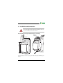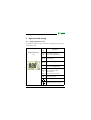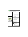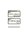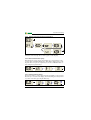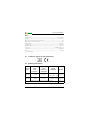
1
Operating Manual GM420 Loop monitor to monitor the PE conductor in AC systems Software version: D268 V1.0x Power in electrical safety TGH1413en/09.2007 Bender Inc. USA: 700 Fox Chase Coatesville, PA 19320 Toll Free: 800-356-4266 Phone: 610-383-9200 Fax: 610-383-7100 E-mail: [email protected] Canada: 5810 Ambler Drive, Unit 1 Mississauga, ON L4W 4J5 Toll Free: 800-243-2438 Phone: 905-602-9990 Fax: 905-602-9960 E-mail: [email protected] © Bender Inc. Web: http://www.bender.org All rights reserved. Content subject to change. Table of Contents 1. Effective use of this manual ........................................................................... 5 1.1 1.2 1.3 Notes for the user ............................................................................................. 5 Intended use ...................................................................................................... 5 Fast commissioning of the loop monitor in AC systems ................... 6 2. Safety information ........................................................................................... 7 2.1 2.2 Safety instructions ........................................................................................... 7 Work activities on electrical installations ................................................ 7 3. Function ............................................................................................................. 9 3.1 3.2 3.2.1 3.2.2 3.2.3 3.2.4 3.2.5 3.2.6 3.2.7 3.2.8 3.2.9 3.2.10 3.2.11 3.2.12 3.2.13 3.2.14 Device features ................................................................................................. 9 Function ............................................................................................................... 9 Preset function ............................................................................................... 10 Protected measuring circuit ...................................................................... 11 Automatic self test ........................................................................................ 12 Manual self test .............................................................................................. 12 Functional faults ............................................................................................ 12 Fault memory ................................................................................................. 12 Assigning alarms to the alarm relays K1/K2 ........................................ 12 Time delays t, ton and toff ........................................................................... 12 Start-up delay t ............................................................................................... 13 Response delay ton ....................................................................................... 13 Delay on release toff ...................................................................................... 13 Password protection (on, OFF) ................................................................. 13 Factory setting FAC ...................................................................................... 13 Erasable history memory ............................................................................ 13 4. Installation and connection ......................................................................... 15 5. Operation and setting ................................................................................... 17 TGH1413en/09.2007 3 Table of Contents 5.1 5.2 5.3 5.4 5.5 5.5.1 5.5.2 5.5.3 5.5.4 5.5.5 5.5.6 5.5.7 5.5.8 5.5.9 5.5.10 5.5.11 5.6 5.7 Display elements in use .............................................................................. 17 Function of the operating elements ...................................................... 18 Menu structure ............................................................................................... 19 Display in standard mode .......................................................................... 21 Display in menu mode ................................................................................ 22 Parameter query and setting: Overview ............................................... 22 Setting the response values for loop resistance and the associated hysteresis ................................................................... 25 Setting the response values for extraneous voltage and hysteresis ................................................................................................. 26 Setting the fault memory and operating mode of the alarm relays ......................................................................................... 27 Assigning alarm categories to the alarm relays ................................. 28 Setting time delays ....................................................................................... 31 Factory setting and password protection ............................................ 32 Restoring factory setting ............................................................................ 33 Manual activation of the preset function ............................................. 34 Device information query .......................................................................... 34 History memory query ................................................................................. 34 Preset function/ factory setting ............................................................... 35 Commissioning .............................................................................................. 35 6. Technical data GM420... ............................................................................... 37 6.1 6.2 4 Standards, approvals and certifications ................................................ 40 Ordering information ................................................................................... 40 TGH1413en/09.2007 1. Effective use of this manual 1.1 Notes for the user This manual is intended for experts in electrical engineering and electronics! In order to make it easier for you to find specific text passages or references in this manual and for reasons of comprehensibility, important information is emphasized by symbols. The meaning of these symbols is explained below: Information calling attention to hazards are marked with this warning symbol. Information intended to assist the user to make optimum use of the product are marked with the Info symbol. 1.2 Intended use The loop monitor of the GM420 series is designed to monitor the PE conductor in AC systems. The extraneous voltage Uf between the terminals E and KE must not exceed AC 12 V. The ohmic resistance of the conductor loop and the existing extraneous AC voltage Uf will be indicated on the display. Measurement results can be adversely affected by DC extraneous voltage Uf occurring during the resistance measurement process. Separate supply voltage Us is required. TGH1413en/09.2007 5 Effective use of this manual 1.3 Fast commissioning of the loop monitor in AC systems If you are already familiar with the function of loop monitoring, you can reduce the time for commissioning and connection using this brief description. 1. Check that the PE conductor to be monitored is operated in an AC system. In addition, check that the resistance of the conductor loop is ≤ 66 Ω and that the extraneous voltage is Uf < 12 V. This is the precondition for an automatic setting of the response values (Preset) after the first connection to the supply voltage. When the loop resistance is > 66 Ω, a response value of 100 Ω will automatically be set. 2. Make sure that the loop monitor is in the delivery status (factory setting has not been changed). In case of doubt, restore the factory setting (page 33). 3. When the conditions 1 and 2 are satisfied, you can connect the loop monitor according to the wiring diagram (page 16). Once the device is connected to the supply voltage, the device determines the loop resistance Rm and automatically sets the response value > R for the loop resistance Rm: Response value (> R) = (Rm + 0.5 Ω) x 1.5 Example: Rm = 2.5 Ω Resulting response value: (2.5 Ω + 0.5 Ω) x 1.5 = 4.5 Ω 4. The currently measured loop resistance between the terminals E and KE appears on the display. In addition, you can query the existing extraneous voltage Uf using the UP and DOWN keys. For detailed information about the preset function refer to page 10. Page 35 provides a summary of all factory settings. If you want to reset the loop monitor to its factory settings, refer to the description on page 33. 6 TGH1413en/09.2007 2. Safety information 2.1 Safety instructions In addition to this data sheet, the documentation of the device includes a sheet entitled "Important safety instructions for BENDER products“. 2.2 Work activities on electrical installations All work activities necessary for installation, commissioning or work activities during operation of electrical devices or systems are to be carried out by adequately skilled personnel. Observe the relevant regulations applying to work on electrical installations, in particular DIN EN 50110 or its subsequent regulation. Unprofessional work activities on electrical installations may result in a threat of danger to life and limb! If the equipment is used outside the Federal Republic of Germany, the respective national standards and regulations are to be observed. The European standard EN 50110 is recommended to be used as a directive. TGH1413en/09.2007 7 Safety information 8 TGH1413en/09.2007 3. Function 3.1 Device features Loop monitoring of the PE conductor in AC systems Loop resistance measurement and indication in the range of 0...100 Ω. The extraneous voltage Uf must not exceed A 12 V. Measurement and indication of an existing extraneous voltage Uf of AC 0...50V, even when the resistance measuring circuit has been disconnected to provide protection. Measuring current Im = DC 20 mA Preset function: Automatic setting of the response value for the loop resistance Rm (> R) r.m.s. value measurement of the extraneous AC voltage Uf (> U) Start-up delay, response delay and delay on release Adjustable switching hysteresis for R and U Measured value display via multi-functional LC display Alarm indication via LEDs (AL1, AL2) and changeover contacts (K1, K2) N/C or N/O operation selectable Password protection against unauthorized parameter changing Fault memory can be deactivated 3.2 Function Once the supply voltage is applied, the start-up delay t is activated. Measured resistance and voltage values changing during this time do not influence the switching state of the alarm relays. The devices provide two individually adjustable measuring channels (loop resistance / extraneous voltage Uf). When the measuring quantity exceeds the response value (Alarm 1) or falls below the response value (Alarm 2), the time of the response delays ton 1/2 begins. When the response delay has elapsed, the alarm relays switch and the alarm LEDs TGH1413en/09.2007 9 Function light. When the measuring value exceeds or falls below the release value (response value plus hysteresis) after the alarm relays have switched, the selected release delay toff begins. When toff has elapsed, the alarm relays switch back to their original state. With the fault memory activated, the alarm relays do not change their actual state until the reset button R is pressed. 3.2.1 Preset function After connecting the device for the first time, the response value for the loop resistance (Alarm 1) is automatically set once only to the following value: Response value loop resistance (> R) = (Rm + 0.5Ω) x 1.5 GM420 Extraneous voltage > U (Uf ) Preset operating range Response value >R AC 25 V 0 Ω...∞ Ω (Rm + 0.5 Ω) x 1.5 max. 100 Ω If the measured resistance value is > 66 Ω, the response value will automatically be set to 100 Ω. If loop resistances of approx. ≥ 1 kΩ exist, the preset function will be ineffective. Hence, the previous response value will remain. The message "AL not SEt" appears on the display. If you exit "AL not SEt" with Enter, the response value will be set to 100 Ω. For details on how to change the response value manually refer to page 25. After restoring the factory settings, the preset function is automatically active again. Also refer to page 33. During operation, the preset function can be started manually via the menu SEt. Also refer to page 34. 10 TGH1413en/09.2007 Function 3.2.2 Protected measuring circuit During the loop resistance measurement, the existing extraneous voltage must not exceed specified values. If the extraneous voltage exceeds the limit values, the measuring circuit will be disconnected (Overload OL). This protective mechanism will also be activated when the loop resistance values are too high. A separate measuring circuit ensures that extraneous voltages Uf (>U) of 1...50 V will be monitored! The table below shows the respective switching thresholds and the corresponding messages shown on the display: Uf (> U) Rm (> R) Display Meaning: ≥ 12 V / ≥ ca. 1 kΩ The measuring circuit has been deactivated by the device software. ≥ 15 V / ≥ approx. 5 kΩ The measuring circuit has been additionally deactivated by the device hardware. (additional R). If the extraneous voltage Uf falls below values ≤ 10 V, the loop resistance measuring circuit will be activated again, provided that the measured loop resistance does not exceed the limit of approx. 1 kΩ. TGH1413en/09.2007 11 Function 3.2.3 Automatic self test The device automatically carries out a self test after connecting to the system to be monitored and later every hour. During the self test internal functional faults are detected and will appear in form of an error code on the display. The alarm relays are not checked during this test. By default, K1 signals the faults detected. 3.2.4 Manual self test After pressing the internal test button for > 1.5 s, a self test is performed by the device. During this test, functional faults will be determined and appear in form of an error code on the display. The alarm relays are not checked during this test. While the test button T is pressed and held down, all device-related display elements are indicated on the display. 3.2.5 Functional faults If an internal functional fault occurs, all three LEDs flash. An error code will appear on the display (E01...E32). For example, E08 means: Incorrect internal calibration. In such a case please contact the Bender Service. 3.2.6 Fault memory The fault memory can be deactivated. A stored fault can be deleted by pressing the reset button "R". 3.2.7 Assigning alarms to the alarm relays K1/K2 Different alarm categories can be assigned to the alarm relays K1/K2 via the menu "out". 3.2.8 Time delays t, ton and toff The times t, ton and toff, described below, delay the output of alarms via LEDs and relays. 12 TGH1413en/09.2007 Function 3.2.9 Start-up delay t After connection to the supply voltage, the alarm indication is delayed by the preset time t (0...99 s). 3.2.10 Response delay ton When the response value is reached, the loop monitor requires the response time tan until the alarm is activated. A preset response delay ton (0...99 s) adds up to the device-related operating time tae and delays alarm signalling (total delay time tan = tae + ton). If the fault does not continue to exist before the time of the response delay has elapsed, an alarm will not be signalled. 3.2.11 Delay on release toff When no alarm exists after deactivating the fault memory, the alarm LEDs go out and the alarm relays switch back to their original state. The release delay (0...99 s) allow to maintain the alarm state for the selected period. 3.2.12 Password protection (on, OFF) After activating the password protection (on), settings are only possible when the correct password (0...999) has been entered. If you cannot operate your device because you cannot remember your password, please contact [email protected]. 3.2.13 Factory setting FAC After activating the factory setting, all settings previously changed are reset to delivery status. In addition, the preset function allows automatic adaptation of the response value in relation to the loop resistance. 3.2.14 Erasable history memory The first alarm value that occurs will be stored in this memory. Subsequent alarms do not overwrite this "old“ value. The memory can be cleared using the Clr key in the menu HiS. TGH1413en/09.2007 13 Function 14 TGH1413en/09.2007 4. Installation and connection Ensure safe isolation from supply in the installation area. Observe the installation rules for live working. General dimension diagram and drawing for screw fixing Zubehör/ Accessory ,5 ,1 36 mm 45 67,5 90 mm 31 116 mm ,5 47 100 mm 70 The front plate cover is easy to open at the lower part marked by an arrow. TGH1413en/09.2007 15 Installation and connection 1. DIN rail mounting: Snap the rear mounting clip of the device into place in such a way that a safe and tight fit is ensured. Screw fixing: Use a tool to move the rear mounting clips (a second mounting clip is required, see ordering information) to a position that it projects beyond the enclosure. Then fix the device using two M4 screws. 2. Wiring Connect the device according the wiring diagram. L1 ~/+ A1 A2 L2 L3 PE E KE M E Terminal 6A Us ~/ IT-System 6A A1 A2 KE Connections A1, A2 Connection to supply voltage Us E Connection to PE conductor (equivalent to functional earth) KE Connection to monitoring conductor E. 11, 12, 14 Alarm relay K1 21, 22, 24 Alarm relay K2 16 TGH1413en/09.2007 5. Operation and setting 5.1 Display elements in use A detailed description of the meaning of the display elements is given in the table below. Eleme nt Display elements in use Function > R Loop resistance (Alarm 1) > U~ Extraneous voltage (Alarm 2) 1, r1 Alarm relay K1 R2, r2 Alarm relay K2 R, U Response value hysteresis Hys % as % OL ton1 ton2 t toff M Response value (that is non-adjustable) is exceeded (Overload) Response delay ton1 (K1) Response delay ton2 (K2) Start-up delay t Delay on release toff K1, K2 Fault memory active Operating mode of the relays K1, K2 Password protection activated TGH1413en/09.2007 17 Operation and setting 5.2 Function of the operating elements Device front Eleme nt Function ON Power On LED, green AL1 LED Alarm 1 lights (yellow): Response value > R exceeded LED Alarm 2 lights (yellow): Response value > U reached AL2 0.9 Ω Display in standard mode: ON T AL1 AL2 R M t Test button (> 1.5 s): To indicate the available display elements, to start a self test; Up key (< 1.5 s): Menu items/values R Reset button (> 1.5 s): Deleting the fault memory; Down key (< 1.5 s): Menu items/values MENU MENU 18 Rm = 0.9 Ω; Fault memory active MENU key (> 1.5 s): Starting the menu mode; Enter key (< 1.5 s): Confirm menu item, submenu item and value. Enter key (> 1.5 s): Back to the next higher menu level TGH1413en/09.2007 Operation and setting 5.3 Menu structure All adjustable parameters are listed in the columns "menu item" and "adjustable parameters". A display-like representation is used to illustrate the parameters in the column menu item. Different alarm categories can be assigned to the alarm relays K1, K2 via the submenus r1, r2. This is done by activation or deactivation of the respective function. Menu Submenu: AL (response values) Menu Activati item on >R - Loop resist. in Ω (Alarm 1) R Hys - Hysteresis, > R >U - Extran. voltage (Alarm 2) U Hys - Hysteresis, extran. voltage M ON 1 2 1 Err r1 out (output control) (K1: (assignment alarm category) r2 (K2: (assignment alarm category) TGH1413en/09.2007 Adjustable parameter Fault memory (on, off) - Operating mode K1 (n.o.) - Operating mode K2 (n.o.) ON Device error at K1 r1 > R ON Loop resistance at K1 too high 1 ON Measuring current disconnection at K1 OL r1 > U off Extran. voltage at K1 1 tES off Manual device test at K1 2 Err off Device error at K2 r2 > R off Loop resistance at K2 too high 2 OL off Measuring current disconnection at K2 r2 > U ON Extraneous voltage K2 2 tES off Manual device test at K2 19 Operation and setting t (timing check) t on 1 Response delay K1 t on 2 Response delay K2 t t off FAC 20 Restore factory settings PrE Manual preset SYS Function blocked Display hard / software version InF HiS Delay on release K1/K2 Parameter setting via password Set (device control) Start-up delay Clr History memory for the first alarm value, erasable TGH1413en/09.2007 Operation and setting 5.4 Display in standard mode By default, the resistance between the terminals E and KE is indicated on the display. In the standard mode, the currently measured values of the loop resistance or extraneous voltage can be displayed by using the Up and Down keys. In order to change the default display, confirm your choice with Enter. TGH1413en/09.2007 21 Operation and setting 5.5 Display in menu mode 5.5.1 Parameter query and setting: Overview Menu item AL out Configuration of the fault memory and the alarm relay: – Activating/deactivating the fault memory – Select N/O operation (n.o.) or N/C operation (n.c.) individually for each K1/K2 – Assign the alarm categories loop resistance, extraneous voltage or device error individually to each K1/ K2 (1, r1 / 2, r2). t 22 Adjustable parameter Response values query and setting: – Loop resistance: > R (AL1) – Hysteresis of the response value: Hys > R – Extraneous voltage: > U (AL2) – Hysteresis of the response value: Hys > U Setting delays: – Response delay ton1/ton2 – Start-up delay t – Delay on release toff (LED, relay) Set Device control parameter setting: – Enable or disable password protection, change the password – Restore factory setting; – Starting preset function PrE; – Service menu SyS blocked InF Query hard and software version HiS Query the first stored alarm value ESC Move to the next higher menu level (back) TGH1413en/09.2007 Operation and setting Menu structure t >1,5 s t > 1,5 s t < 1,5 s AL out t SEt InF HiS ESC t < 1,5 s t > 1,5 s ESC TGH1413en/09.2007 23 Operation and setting Parameter settings An example is given below on how to change the alarm response value for the loop resistance > R. Proceed as follows: 1. Press the MENU/Enter key for more than 1.5 seconds. The flashing short symbol AL appears on the display. 2. Confirm with Enter. The symbols > R flash. 3. Confirm with Enter. the current value for Ω flashes. 4. Use the Up or Down key to set the appropriate response value. Confirm with Enter. > R flashes. 5. You can exit the menu by: – Pressing the Enter key for more than 1.5 seconds to reach the next higher level or – selecting the menu item ESC and confirming with Enter to reach the next higher level. The currently active segments are flashing! In the figures below, the segments where device settings can be carried out are highlighted by an oval. The menu mode can be reached by pressing the MENU key for more than 1.5 seconds. 24 TGH1413en/09.2007 Operation and setting 5.5.2 Setting the response values for loop resistance and the associated hysteresis Set the resistance value at which an alarm is to be signalled. Setting the response value for the loop resistance 2x >1,5 s Setting the hysteresis of the resistance response value 1x 2x >1,5 s TGH1413en/09.2007 25 Operation and setting 5.5.3 Setting the response values for extraneous voltage and hysteresis Set the extraneous voltage response value at which an alarm is to be signalled. Setting the extraneous voltage response value (> U) 2x 2x >1,5 s Setting the hysteresis for extraneous voltage 3x 2x >1,5 s 26 TGH1413en/09.2007 Operation and setting 5.5.4 Setting the fault memory and operating mode of the alarm relays Deactivating the fault memory 2x >1,5 s Setting the alarm relay K1 to N/C operation (n.c.) 1x 2x >1,5 s TGH1413en/09.2007 27 Operation and setting 5.5.5 Assigning alarm categories to the alarm relays Loop resistance, extraneous voltage and device-related errors can be assigned to the alarm relays K1 (r1, 1) and K2 (r2, 2). By default, K1 signals an alarm in case of too high loop resistance. K2 signals an alarm in case of too high extraneous voltage Uf. A few assignment examples for alarm relay K1 are illustrated below: Alarm relay K1: Deactivating the category device error 3x 3x >1,5 s Alarm relay 1: Deactivating the category loop resistance 3x 1x 3x >1,5 s 28 TGH1413en/09.2007 Operation and setting Alarm relay 1: Deactivating the category measuring current disconnection 3x 2x 3x >1,5 s Alarm relay 1: Activating the category extraneous voltage 3x 3x 3x >1,5 s TGH1413en/09.2007 29 Operation and setting Alarm relay 1: Activating the category manual self test 3x 4x 3x >1,5 s When an alarm relay (K1/K2) has been deactivated in the menu, an alarm will not be signalled by the respective changeover contact! An alarm will only be indicated by the respective alarm LED (AL1/AL2)! 30 TGH1413en/09.2007 Operation and setting 5.5.6 Setting time delays Use this segment to set a response delay ton1 (0...99 s) for K1, ton2 (0...99 s) for K2, a starting delay t (0...99 s) when starting the device, as well as a common release delay toff (0...99 s) for K1, K2. This setting is only relevant when the fault memory M is deactivated. The operating steps for the setting of the response delay ton1 and the start-up delay t are illustrated by way of example. Setting the response delay ton1 2x >1,5 s Setting the start-up delay t 2x 2x >1,5 s TGH1413en/09.2007 31 Operation and setting 5.5.7 Factory setting and password protection Use this menu to activate the password protection, to change the password or to deactivate the password protection. In addition, you can reset the device to its factory settings. a) Activating the password protection 2x >1,5 s b) Changing the password 2x >1,5 s 32 TGH1413en/09.2007 Operation and setting c) Deactivating the password protection 2x >1,5 s 5.5.8 Restoring factory setting .... TGH1413en/09.2007 33 Operation and setting 5.5.9 Manual activation of the preset function 2x .... 3x >1,5 s If loop resistances of approx. ≥ 1 kΩ exist, the preset function will be ineffective. The message "AL not SEt“ appears on the display. 5.5.10 Device information query This function is used to query the hardware (d...) and software (1.xx) versions. After activating this function, data will be displayed as a scrolling text. Once one pass is completed you can select individual data sections using the Up/Down keys. .... .... 5.5.11 History memory query The history memory can be selected via the menu HiS. Use the Up and Down keys to view the next display. If Clr is flashing, the history memory can be cleared by pressing the Enter key. 34 TGH1413en/09.2007 Operation and setting 5.6 Preset function/ factory setting On initial commissioning, a pre-defined response value in relation to the measured resistance value Rm is automatically set: Response value loop resistance: (> R) = (Rm + 0,5 Ω) x 1.5 Hysteresis (R Hys): Extraneous voltage (> U) Hysteresis (U Hys): Fault memory M: Operating mode K1 (> R): Operating mode K2 (> U): Start-up delay: Response delay: Delay on release: Password: 25 % 25 V 5% ON N/O operation (n.o.) N/O operation (n.o.) t=0s ton1 = 0 s ton2 = 0 s toff = 0.5 s 0, Off 5.7 Commissioning Prior to commissioning, check proper connection of the GM420. After connecting a brand-new GM420 to the supply voltage, the loop resistance response value is automatically set by the internal preset function: (> R) = (Rm + 0,5 Ω) x 1.5 (Rm = measured loop resistance) TGH1413en/09.2007 35 Operation and setting 36 TGH1413en/09.2007 6. Technical data GM420... ( )* = factory setting Insulation coordination acc. to IEC 60664-1 / IEC 60664-3 Rated insulation voltage ....................................................................................................................................... 400 V Rated impulse voltage/pollution degree........................................................................................................... 4 kV / III Protective separation (reinforced insulation) between ....................... (A1, A2) - (E ,KE) - (11-12-14) - (21-22-24) Voltage test acc. to IEC 61010-1: (E ,KE) - [(A1-A2), (11-12-14)] ....................................................................................................................... 3.32 kV (E ,KE) - (21-22-24) .......................................................................................................................................... 2.21 kV (A1- A2) - (11-12-14) - (21-22-24) ............................................................................................................... 2.21 kV Supply voltage GM420-D-1: Supply voltage Us ............................................................................................................... AC 16...72 V / DC 9.6...94 V Frequency range Us ...................................................................................................................................... 15...460 Hz GM420-D-2: Supply voltage Us ............................................................................................................................... AC/DC 70...300 V Frequency range Us ...................................................................................................................................... 15...460 Hz Power consumption ......................................................................................................................................... ≤ 3.5 VA Measuring circuit Loop resistance Rm: Measuring range Rm ...................................................................................................................................... 0...100 Ω Measuring current Im ...................................................................................................................................... DC 20 mA Measuring voltage Um ................................................................................................................................... ≤ DC 24 V Extraneous voltage Uf: Measuring range Uf ....................................................................................................................................... AC 0...50 V Nominal frequency fn ................................................................................................................................... 42...460 Hz Disconnection of the measuring loop Uf .......................................................................................................... ≥ 12 V Reclosing of the measuring loop.......................................................................................................................... ≤ 10 V Permissible extraneous voltage Uf ................................................................................................................. ≤ 440 V Permissible extraneous DC voltage, without influence on the measurement ................................................... DC 0 V TGH1413en/09.2007 37 Technical data GM420... Response values Loop resistance (> R) (Alarm 1) ................................................................................................................ 0.1...100 Ω Resolution of setting R 0.1...10 Ω ...................................................................................................................... 0.1 Ω Resolution of setting R 10...100 Ω ........................................................................................................................ 1 Ω Preset function: Loop resistance (> R) .......................................................................................................... = ((Rm + 0.5 Ω) x 1.5) * Relative percentage error 0...1 Ω ..................................................................................................... ±20 %, ±1 digit Relative percentage error 1...10 Ω ..................................................................................................... ±5 %, ±1 digit Relative percentage error 10...100 Ω ................................................................................................. ±5 %, ±1 digit Hysteresis (> R) ................................................................................................................................ 1...40 % (25 %)* Extraneous voltage Uf (> U) (Alarm 2) ............................................................................................ 1...50 V (25 V)* Resolution of setting Uf 1...50 V .......................................................................................................................... 0.5 V Relative percentage error Uf (> U) in the range 50/60 Hz .................................................................. ±2 %, ±1 digit Relative percentage error Uf (> U) in the range 42...460 Hz ........................................................... ±10 %, ±1 digit Hysteresis > U ..................................................................................................................................... 1...40 % (5 %)* Specified time Start-up delay .......................................................................................................................................... 0...99 s (0 s)* Response delay ton1/2 ............................................................................................................................. 0...99 s (0 s)* Release delay toff ................................................................................................................................... 0...99 s (0.5 s)* Operating time tae when the loop is open (R > 50 kΩ) ............................................................................... ≤ 40 ms Operating time tae when the loop is closed (> R) ........................................................................................ ≤ 500 ms Operating time tae if extraneous voltage Uf (> U) and overload (OL) exist ................................................ ≤ 100 ms Response time tan .............................................................................................................................. tan = tae + ton1/2 Recovery time tb ............................................................................................................................................. ≤ 300 ms Recovery time tb after protective disconnection.................................................................................................... ≤ 1 s Displays, memory Display..................................................................................................... LC display, multi-functional, not illuminated Display range, measured value Rm ................................................................................................................ 0...100 Ω Display range, measured value Uf ................................................................................................................ AC 0...50 V Operating error, loop resistance 0...1 Ω ............................................................................................ ±20 %, ±1 digit Operating error, loop resistance 1...100 Ω .......................................................................................... ±5 %, ±1 digit Operating error, voltage in the range 50/60 Hz ................................................................................... ±2 %, ±1 digit Operating error, voltage in the range 42...460 Hz ............................................................................. ±10 %, ±1 digit History memory (HiS) for the first alarm value............................................................... data record measured values 38 TGH1413en/09.2007 Technical data GM420... Password ........................................................................................................................................... off / 0...999 (off)* Fault memory (M) alarm relay ................................................................................................................ on / off (on)* Switching elements Number of changeover contacts ............................................................................................................... 2 x 1 (K1, K2) Operating principle ....................................................................................................... N/C operation / N/O operation .. K1: Err, > R, OL, > U, tES (device error, loop resistance, measuring current disconnection: N/O operation n.o.)* ...................................................................................... K2: Err, > R, OL, > U, tES (overvoltage: N/O operation n.o.)* Electrical service life under rated operating conditions, number of cycles .................................................................................................................................................. 10000 Contact data acc. to IEC 60947-5-1: Utilization category ................................................................................................. AC 13 AC 14 DC-12 DC-12 DC-12 Rated operational voltage ........................................................................................... 230 V 230 V 24 V 110 V 220 V Rated operational current ......................................................................................................... 5 A 3 A 1 A 0.2 A 0.1 A Minimum contact load..............................................................................................................1 mA at AC / DC ≥ 10 V Environment / EMC EMC ................................................................................................................................................................. IEC 61326 Operating temperature ......................................................................................................................... -25 ºC...+55 ºC Classification of climatic conditions acc. to IEC 60721: Stationary use (IEC 60721-3-3) ........................................................3K5 (except condensation and formation of ice) Transportation (IEC 60721-3-2) ........................................................2K3 (except condensation and formation of ice) Storage (IEC 60721-3-1) ...................................................................1K4 (except condensation and formation of ice) Classification of mechanical conditions acc. to IEC 60721: Stationary use (IEC 60721-3-3) .............................................................................................................................. 3M4 Transportation (IEC 60721-3-2) .............................................................................................................................. 2M2 Storage (IEC 60721-3-1) ......................................................................................................................................... 1M3 Connection Connection..............................................................................................................................................screw terminals Connection properties: rigid/ flexible/ conductor sizes .......................................................................... 0.2...4 / 0.2...2.5 mm2 / AWG 24...12 Multi-conductor connection (2 conductors with the same cross section): rigid/ flexible .................................................................................................................. 0.2...1.5 mm2 / 0.2...1.5 mm2 Stripping length ............................................................................................................................................... 8...9 mm Tightening torque....................................................................................................................................... 0.5...0.6 Nm TGH1413en/09.2007 39 Technical data GM420... Other Operating mode ........................................................................................................................... continuous operation Mounting ......................................................................................................................................................any position Degree of protection, internal components (IEC 60529)......................................................................................... IP30 Degree of protection, terminals (IEC 60529) .......................................................................................................... IP20 Enclosure material ....................................................................................................................................polycarbonate Flammability class ............................................................................................................................................UL94 V-0 DIN rail mounting acc. to................................................................................................................................. IEC 60715 Screw fixing ......................................................................................................................... 2 x M4 with mounting clip Software version .......................................................................................................................................... D268 V1.0x Weight ............................................................................................................................................................... ≤ 150 g ( )* = Factory setting 6.1 Standards, approvals and certifications 6.2 Ordering information Device type Measuring range Loop resistance Measuring range extraneous voltage Uf GM420-D-1 0...100 Ω AC 0...50 V DC 9.6 V...94 V / B 9308 2001 AC 15...460 Hz, 16...72 V GM420-D-2 0...100 Ω AC 0...50 V DC 70...300 V / B 9308 2002 AC 15...460 Hz, 70...300 V Supply voltage Us Mounting clip for screw fixing (1 piece per device, accessories) 40 Art. No. B 9806 0008 TGH1413en/09.2007 INDEX A Adjustable parameters, list 19 Automatic self test 12 C currently measured values - Extraneous voltage 21 - Loop resistance 21 D Delay on release toff 13 Deleting the fault alarms 18 Device features 9 Display elements in use 17 Display in menu mode 22 Display in standard mode 21 E ENTER key 18 Example of parameter setting 24 F factory 35 factory setting 13, 35 Fast commissioning 6 Fault memory 12 Function 9 Functional faults 12 TGH1413en/09.2007 I Installation and connection 15 K K1: assignment alarm category 19 K2: assignment alarm category 19 L LED Alarm 1 lights 18 LED Alarm 2 lights 18 M Manual self test 12 Manual, target group 5 Menu - AL (response values) 19 - HiS (history memory for the first alarm value) 20 - InF (hard and software version) 20 - out (output control) 19 - Set (device control) 20 - t (timing check) 20 Menu structure 19 Mounting clip for screw fixing 40 N Notes for the user 5 41 O Operating elements, function 18 Operation and setting 17 Ordering information 40 P Parameter query and setting - 22 Parameter setting - Activating or deactivating the password protection 32 - Assigning alarm categories to the alarm relays 28 - Deactivating the fault memory 27 - Manual activation of the preset function 34 - Setting response values 25 - Setting the operating principle of the alarm relays 27 - Setting time delays 31 Password protection 13 Preset function 10 Protected measuring circuit 11 - Hysteresis extraneous voltage 26 - Loop resistance > R 25 - Loop resistance hysteresis 25 Starting delay t 31 Starting the menu mode 18 Start-up delay t 13 T Technical data 37 Test button 18 Time delays 9, 12 W Wiring diagram 16 Work activities on electrical installations 7 R Reset button 18 Response delay ton 13, 31 S Setting response values - Extraneous voltage (> U) 26 42 TGH1413en/09.2007 Bender Inc. USA: 700 Fox Chase Coatesville, PA 19320 Toll Free: 800-356-4266 Phone: 610-383-9200 Fax: 610-383-7100 E-mail: [email protected] Canada: 5810 Ambler Drive, Unit 1 Mississauga, ON L4W 4J5 Toll Free: 800-243-2438 Phone: 905-602-9990 Fax: 905-602-9960 E-mail: [email protected] Web: http://www.bender.org