1
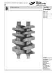
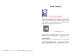
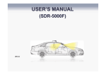
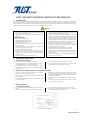
JUST SOLAR PV MODULE INSTALLATION MANUAL 1. INTRODUCTION The user manual contains information regarding the installation and safe handling of Justsolar PV modules . All instructions should be read and understood before attempting installation. If there are any questions, please contact your dealer or Just solar for further information. The installer should conform to all safety precautions in the manual when installing modules. Before installing a solar PV system, the installer should become familiar with the mechanical and electrical requirements for PV system. Keep this user manual in a safe place for future reference. WARNING GENERAL USE INSTALLATION DO NOT use the PV module where failure could result in death, personal injury or damage to property. Make certain that PV module conforms to the specifications for the total system. GENERAL HANDLING 2. A. Handle the PV module with care. DO NOT disassemble the PV module. DO NOT alter or remove any component. DO NOT bend the PV module. DO NOT stand or step on a module to avoid personal injury and the damage to a module. DO NOT impact on front or rear surface of the PV module. Rear surface may be damaged by sharp objects. DO NOT throw and drop the PV module. DO NOT touch live parts of wires, cables, connectors, or junction boxes. Be sure the circuit breaker is off if it is applicable. Always use appropriate safety equipment (insulated tools, insulating gloves, insulating shoes, etc.). DO NOT use the cables or connectors as a handle. Installers should be qualified personnel who are experienced with electrical work and the installation of PV systems. DO NOT use damaged PV modules. A damaged PV module may cause a fire or an electrical shock with personal injury or even death. DO NOT expose the PV module to artificially concentrated sunlight. Cover the front surface of the PV module with an opaque cloth or other material when installing and repairing. The PV module exposed to sunlight generates a high voltage and current. Contact with the module output wiring may cause a fire or an electrical shock. Fasten the PV modules to the mounting frame firmly so that the modules will not be affected by wind and snow loads. The frame should meet relevant building standards. DO NOT block frame drain holes at each corner of module. Ground securely the PV modules and the mounting frame. Install the PV modules securely and properly to avoid accidents with personal injury or even death and damage to property by accumulated snow. Connect a circuit breaker or some equipment to detect the leakage current and then break the circuit. MECHANICAL INSTALLATION SELECTING THE LOCATION Select a suitable location for installation of the module. For optimum performance, the module must be facing true south in northern latitudes and true north in southern latitudes. For detailed information on optimal module orientation, refer to standard solar PV installation guides or a reputable solar installer or systems integrator. The modules should not be shaded at any time of the day. DO NOT install the module near equipment or in locations where flammable gases can be be generated or collected. B. SELECTING THE PROPER MOUNTING STRUCTURE AND HARDWARE Observe all instructions and safety precautions included with the mounting system to be used with the modules. DO NOT drill holes in the glass surface of the modules. Doing so will void the warranty. DO NOT drill additional mounting holes in the module frame. Doing so will void the warranty. C. Modules must be securely attached to the mounting structure using four mounting points for normal installation. If heavy wind or snow loads are anticipated, additional mounting points should also be used. Please see the drawing below. Load calculations are the responsibility of the system designer or installer. The mounting structure and hardware must be made of durable, corrosion- and UV- resistant material. MOUNTING METHODS a. MOUNTING WITH BOLTS Use the 4 corner holes of the PV module to bolt (M8) to the mounting frame. When more strength is required, use all 8 holes on two long sides. Use spring washers and flat washers to fasten the PV module. Install the PV module securely such as fastening the appropriate bolts with double nuts and locking washers. Fig. 1 Mounting to frame (Reference) 1/4 www.just-solar.net b. MOUNTING WITH CLIPS Base profile should be placed in perpendicular to the longer side frame of module in principle. Module shall be fixed at 4 places or more on the longer side frames. Refer to the figure and table for the allowable area to be fixed. Close the gap between the material and frame, and secure without losing by M6 or larger bolts (M8) for where the heavy snow load is expected. The clip centerlines must be between 1/8L and 1/4L on the long sides of the modules. Note that the mounting clips should meet the minimum dimensions (catch width of 5mm and length of 30mm). Use the clipping material with sufficient strength and the shape that can withstand forces from wind pressure and snowfall pressure specific to local climate. The tightening torque (using stainless steel M8) must be more than 15 Nm. Add some measure to prevent the module from unfastening or sliding down so that the fallen module doesn’t cause any damage for person or property. Fig. 2 Clipping method 3. c. INSTALLATION SUPPORT AT SEA-SIDE(SAIL MIST AND HIGH WIND) CONDITION If mounting with bolts, all 8 mounting holes must be used with M8 bolts. If mounting with clamps, the tightening torque (using stainless steel M8) must be more than 15 Nm. The oxidation film of PV modules’ frame must be more than 16 micron. All mounting structure and installation components must be hot galvanized before used. ELECTRICAL INSTALLATION WARNING Safety class in accordance with IEC 61140 Only authorized and trained personnel should have access to PV modules. The system involves electricity, and can be dangerous if the personnel are not familiar with the appropriate safety procedures. A. GROUNDING All module frames must be properly grounded. Observe all local electric codes and regulations. A bonding or toothed washer is required to make proper and reliable electrical grounding connection with the anodized aluminum frame. a. Devices listed and identified for grounding metallic frames of PV modules are permitted to ground the exposed metallic frames of the module to grounded mounting structure. Grounding the module properly as appropriate for the conditions t the installation site. Method #1 Secure the stainless steel screw to the grounding hole. As shown in the figure 3, copper wire should be compressed by the screw head. Stainless steel washer with appropriate corrosion resistant coating should be inserted between copper wire and the frame to avoid galvanic corrosion. Proper cupped washer should be inserted between copper wire and screw head. Fig. 3 Grounding method #1 2/4 www.just-solar.net b. Method #2 If the mounting holes are not used to fix the module, one of them can be used for grounding. The appropriate device like “grounding lug” as shown in the figure 4 should be secured by stainless steel bolt, nut and washers. Toothed washer shall be inserted between the nut and the frame to break the anodized layer of frame. Stainless steel washer with appropriate corrosion resistant coating should be inserted between the grounding lug and frame. Fig. 4 Grounding method #2 WARNING DO NOT short the positive and negative cables. Make sure connectors are fully engaged without a gap between the insulators and shall be locked. In case there is a gap, a fire or an eletrical shock may occur. CAUTION The PV module has a pair of male and female waterproof connectors. For a series electrical connection, connect the positive connector of the first PV module to the negative connector of the following module. Connect the output cable to the other equipment in the system correctly. Connect the required number of PV modules to meet the voltage specification for equipment used in the PV system. Wire the output cable connectors so that they do not exert any force or pressure on the PV module’s junction box. Attach the cable to the mounting frame using approved fasteners. The connectors should be placed behind the mounting frame so that the connectors can’t be directly exposed to sunlight, wind and rain. To extend the cable, use proper commercial cables and connectors that can withstand outdoor use for long periods. Select the appropriate cable size according to its length to avoid voltage drop. Note: For field connection use minimum No. 10 AWG copper wires insulated for a minimum of 90°C. B. ELECTRICAL RATINGS OF THE CONCERNED MODULES Type JST-M160M JST- M165M JST- M170M JST-M175M JST-M180M Max Power Pm(W) 160 165 170 175 180 185 Max-Power Voltage Vm(V) 34.9 35.6 35.8 36.2 36.8 37.5 Max-Power Current Im(A) 4.60 4.65 4.76 4.85 4.90 4.95 Open-Circuit Voltage Voc(V) 42.8 43.2 43.6 43.9 44.2 44.5 Short-Circuit Current Isc(A) 5.15 5.20 5.25 5.30 5.35 5.40 15.0% 15.5% 16.0% 16.5% 17.0% 17.5% Cell Efficiency Maximum System Voltage(V) 1000(TUV)/600(UL) Maximum Series Fuse Rating(A) 15 Power Tolerance Type ±3% JST-M180P JST-M190P JST-M200P Max Power Pm(W) 180 190 200 210 Max-Power Voltage Vm(V) 26.5 26.8 27.2 27.5 Max-Power Current Im(A) 6.80 7.10 7.36 7.63 Open-Circuit Voltage Voc(V) 32.4 32.5 32.7 32.8 Short-Circuit Current Isc(A) 7.60 7.72 7.86 7.98 13.7% 14.5% 15.2% 16.0% Cell Efficiency Maximum System Voltage(V) Maximum Series Fuse Rating(A) Power Tolerance JST-M185M JST-M210P 1000(TUV)/600(UL) 20 ±3% 3/4 www.just-solar.net Type JST-M200P JST-M210P JST-M220P JST-M230P JST-M240P Max Power Pm(W) 200 210 220 230 240 Max-Power Voltage Vm(V) 29.5 29.5 30 30 30 Max-Power Current Im(A) 6.90 7.20 7.40 7.66 8.00 Open-Circuit Voltage Voc(V) 36.0 36.0 36.6 37.0 37.4 Short-Circuit Current Isc(A) 7.60 7.80 8.10 8.38 8.55 13.70% 14.4% 15.1% 15.8% 16.4% Cell Efficiency Maximum System Voltage(V) 1000(TUV)/600(UL) Maximum Series Fuse Rating(A) 20 Power Tolerance Type ±3% JST-M250P JST-M260P JST-M270P Max Power Pm(W) 250 260 270 280 Max-Power Voltage Vm(V) 34.6 34.8 35 35.2 Max-Power Current Im(A) 7.23 7.47 7.71 7.95 Open-Circuit Voltage Voc(V) 43.7 44.0 44.5 44.8 Short-Circuit Current Isc(A) 7.98 8.09 8.20 8.33 14.3% 14.8% 15.4% 16.0% Cell Efficiency Maximum System Voltage(V) Maximum Series Fuse Rating(A) Power Tolerance JST-M280P 1000(TUV)/600(UL) 20 ±3% Note: The electrical characteristics are within +/-10% of the indicated values of Isc, Voc and Pm under Standard Test Conditions (Irradiance of 1000W/㎡, AM 1.5 spectrums and a cell temperature of 25℃). 4. MAINTENANCE Just solar recommends the following maintenance items to ensure optimum performance of the module: DO NOT touch live parts of wires, cables, connectors and junction boxes. Be sure the circuit breaker is off, if it is applicable. Always use appropriate safety equipment (insulated tools, insulated gloves, etc.). Clean the glass surface of the modules as necessary. Use water and a soft sponge or cloth for cleaning. A mild, non-abrasive cleaning agent can be used if necessary. Do not use dishwasher detergent. Electrical and mechanical connections should be checked periodically by qualified personnel to verify that they are clean, secure and undamaged. Check if nuts, bolts of mounting frame are secure and not loose. Tighten all loose components. Check connections of cables, grounding cables and connectors. Check all electrical and mechanical connections for freedom from corrosion. Check the grounding resistance of metal parts such as the module frame and the mounting frame. ATTENSION Do NOT concentrate solar light on the module as it has not been designed for this use Just solar PV modules are qualified for safety through IEC 61730 - 1 and within this application class is considered to meet the requirements of IEC 61730 Just solar PV module assembly is to be mounted over a fire resistant roof covering rated for the application Under normal conditions, a photovoltaic module is likely to experience conditions that produce more current and/or voltage than reported at standard test conditions. Accordingly, the values of ISC and VOC marked on this module should be multiplied by a factor of 1.25 when determining component voltage ratings, conductor ampacities, fuse sizes and size of controls connected to the PV output. class A (class II). WARNING Failure to perform the checks and minimum maintenance operations established in this instruction manual will lead to the withdrawal of all guarantees of JUST SOLAR CO., LIMITED. for any responsibilities which may be derived from such failure. 4/4 www.just-solar.net