1
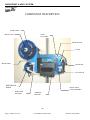
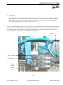
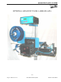
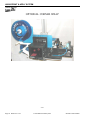
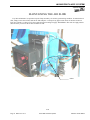
LM-3605 PRINT & APPLY SYSTEM
USER’S MANUAL
TABLE OF CONTENTS
SECTION
PAGE
1. APPLICATOR OVERVIEW
Introduction
General Printer Specifications
Inventory List
Print & Apply Component Description
User Responsibility
Safety
1-01
1-02
1-03
1-04
1-05
1-05
2. SETUP AND OPERATION
Web Routing
Thermal Print Head Label Loading
Thermal Ribbon Loading
Label Sensor Adjustment
Take Up Unit Assembly
Clutch Assembly Adjustment
Hand Held Labeler Interface HLI-100
Accessory Connections Control Box
Communication Connections Control Box
T-50 Photo Eye
Air assist tube
T-150 Mounting Stand (optional)
T-stand adjustment
Tamp Unit Operation
Tamp Flow Control Adjustment
Optional Adjacent Panel Labeler (APL)
Optional Corner Wrap
2-01
2-03
2-03
2-03
2-04
2-05
2-06
2-07
2-08
2-09
2-10
2-11
2-12
2-13
2-14
2-15
2-16
3. CONTROL BOX
Programming
Quick Reference Chart
Key Definitions
Set Up Of Key Features
Description of I/O
3-01
3-05
3-15
3-16
3-20
4. CLEANING & MAINTENANCE
Troubleshooting
Fault Codes
Cleaning of the Print Head
Cleaning the Platen, Demand Plate and Rollers
Replacing the Print Head Power Fuse
Maintaining The Air Slide
Replacing Main Power Fuse
Page 1
Made in the U.S.A.
© 2007 MMI Automated Systems
4-01
4-02
4-03
4-03
4-03
4-04
4-05
5/25/2007 Model LM3605
LM3605 PRINT & APPLY SYSTEM
USERS MANUAL
SECTION 1
APPLICATOR OVERVIEW
Introduction
General Printer Specifications
Inventory List
Print & Apply Component Description
User Responsibility
Safety
Page 2
Made in the U.S.A.
© 2007 MMI Automated Systems
1-01
1-02
1-03
1-04
1-05
1-05
5/25/2007 Model LM3605
LM-3605 PRINT & APPLY SYSTEM
USER’S MANUAL
LABEL MILL 3605
THERMAL PRINTER/APPLICATOR SYSTEM
INTRODUCTION
The Label-Mill 3605 is a state of the art THERMAL PRINTER & APPLICATOR SYSTEM created with maximum
flexibility for your AUTOMATIC LABELING NEEDS. The unit will print and apply high quality labels and bar codes to
your product at print speeds up to 6”/sec. and apply at speeds up to 60 labels/min.
OPERATION
The standard configuration is External Computer Mode. The configuration allows label formats to be sent to the standard
Centronics Parallel Interface Port, or serial port, on the Printer/Applicator. Once the format is downloaded to the Printer Job
Buffer, the system 3605 can print and apply as normal. Standard industry label software packages can be used in conjunction
with a PC to design and load label design.
1-01
Page 3
Made in the U.S.A.
© 2007 MMI Automated Systems
5/25/2007 Model LM3605
LM3605 PRINT & APPLY SYSTEM
USERS MANUAL
SPECIFICATIONS
PRINT SPEED
Up to 6”/second and approx. 60 labels/min.
(Varies depending on label and product size.)
BAR CODES
UPC-A, UPC-E, EAN-8,EAN-13, Code 39, Int. 2 of 5, Code 128, MSI 2 of
5, UPC Bookland, and CODABAR.
BAR CODE RATIOS
1:2, 1:2.5, 1:3 or individually programmable bar code widths
HUMAN READABLE FONTS
Eight fonts including OCR-A and OCR-B representation and an outline font.
American and European fonts. Upper case and lower case with decendors
plus memory available for custom fonts.
LABEL ROLL CAPACITY
12” Max. outside diameter wound on a 3” diameter core. Die cut waste
removed with a minimum of 1/8” separation between labels in running
direction.
LABEL SIZE
Minimum: 1” wide x ¾” long
Maximum: 7.2” wide x 14” long
MAXIMUM PRINT AREA
4.0” wide x 14” long
LABEL PLACEMENT
ACCURACY
Up to + or - 1/32” (1mm) when labels are produced to specifications and
product handling is controlled.
PRINTING METHOD
Thermal Transfer and Direct Thermal
Print application method…Standard Tamp, Optional Blow On and Wipe On.
INTERFACE
Standard Centronics Parallel Port
Standard RS-232C Serial Port, Ethernet port
INTERFACE SENSORS
Ribbon out
Product Sensor-Photo Eye-Limit Switch
PLC input
ELECTRICAL
115V AC/60 Hz-250 W idle, 600 W running.
AIR REQUIREMENT
80 p.s.i./3 cfm
SIZE
23” T x 30” W x 23-3/8” D
ENVIRONMENT
Operating Temp. 50-95 F (10-35 C)
15-85% RH. non-condensing
WEIGHT
60 lb. (with U-Arms)
*Options available
1-02
Page 4
Made in the U.S.A.
© 2007 MMI Automated Systems
5/25/2007 Model LM3605
LM-3605 PRINT & APPLY SYSTEM
USER’S MANUAL
INVENTORY LIST
QTY.
1
2
1
2
1
1
1
1
1
Description
Print & Apply Assembly
12-½” dia. Blue Plastic Spools w / Quick Release Collar
7-¾” dia. Blue Plastic Spool w / screws
½” - 13 bolts w / washers
Power Cord
Model 3605 Operators Manual
Extra Cardboard Ribbon Core
Product Switch (specified)
a. Manual Limit Switch (optional)
b. Photo Switch (optional)
Take-up Spool Clip
TOOLS REQUIRED FOR ASSEMBLY
:
3/32” ALLEN WRENCH
¾” WRENCH
1-1/8” WRENCH
1-03
Page 5
Made in the U.S.A.
© 2007 MMI Automated Systems
5/25/2007 Model LM3605
LM3605 PRINT & APPLY SYSTEM
USERS MANUAL
COMPONENT DESCRIPTION
LABEL SPOOL
SPOOL LOCK
TAMP
CYLINDER
REED SWITCH
U-ARM
BRAKE ARM
AIR FILTER
VALVE PACK
WEB TAKE-UP
SPOOL
WEB GUIDE
ROLLERS
SWING AWAY
TAMP ASSEMBLE
THERMAL
PRINTER
1-04
Page 6
Made in the U.S.A.
© 2007 MMI Automated Systems
5/25/2007 Model LM3605
LM-3605 PRINT & APPLY SYSTEM
USER’S MANUAL
USER RESPONSIBILITY
This equipment will perform in conformity with the description thereof contained in this manual and accompanying labels
and / or inserts when installed, operated, maintained, and repaired in accordance with the instructions provided. This
equipment must be checked periodically. Defective equipment should not be used. Parts that are broken, missing, plainly
worn, distorted, or contaminated should be replaced immediately. Should such repair or replacement become necessary, we
recommend that a request for service advice be made.
This equipment or any of its parts should not be altered without the prior written approval of MMI Automated Systems. The
user of this equipment shall have the sole responsibility for any malfunctions which results from improper use, faulty
maintenance, damage, improper repair or alteration by anyone other than MMI Automated Systems or a service facility
designated by MMI Automated Systems.
SAFETY
Only qualified personnel should use this equipment.
Before installing, inspecting or servicing equipment, turn OFF all power and air controls at the source and lock out in
accordance with OSHA Standards.
Be sure all external electrically conductive parts are connected to a good electrical ground.
Never handle live electrical equipment with bare hands while standing in water, or while hands and feet are wet. Dangerous
electrical shock can result.
Whenever the equipment is unattended, turn off all control and power supply switches.
Keep equipment clean and in good operating condition. Promptly repair or replace all worn or damaged hoses, cables or
parts.
Do not make any repairs to equipment unless you are fully qualified.
This equipment contains fast moving parts, which may move without warning. Keep hands, loose hair and clothes clear of
machines at all times.
Never place hands or any other body parts under the label platen at any time.
This equipment uses compressed air. Proper care and maintenance must be taken when handling compressed air and its
components.
These precautions are further detailed and explained where specifically required in this manual.
! WARNING
READ AND UNDERSTAND THESE INSTRUCTIONS
Protect yourself and others. Be sure this information is read and understood by all operators.
ELECTRICAL SHOCK CAN KILL!
Do not touch live electrical parts with bare skin or work with gloves or wet clothing.
NOISE CAN DAMAGE HEARING!
Wear proper ear protection.
1-05
Page 7
Made in the U.S.A.
© 2007 MMI Automated Systems
5/25/2007 Model LM3605
LM3605 PRINT & APPLY SYSTEM
USERS MANUAL
SECTION 2
SETUP AND OPERATION
Web Routing
Thermal Print Head Label Loading
Thermal Ribbon Loading
Label Sensor Adjustment
Take Up Unit Assembly
Clutch Assembly Adjustment
Operator Interface Terminal
Accessory Connector Panel
T-50 Photo Eye
Air Assist Tube
T-150 Mounting Stand (option)
T-stand adjustment
Tamp Unit Operation
Tamp Flow Control Adjustment
Optional Adjacent Panel Labeler (APL)
Optional Corner Wrap
Page 8
Made in the U.S.A.
© 2007 MMI Automated Systems
2-01
2-03
2-03
2-03
2-04
2-05
2-06
2-07
2-07.5
2-08
2-09
2-10
2-11
2-12
2-13
2-14
5/25/2007 Model LM3605
LM-3605 PRINT & APPLY SYSTEM
USER’S MANUAL
WEB ROUTING
Step
Operation
1
2
Load web onto label storage spool (A) so it unloads in a clockwise direction. (refer to pg. 2-2)
Feed the web to the left and below roller guide (B), to the right of roller (C) and to the left and
below roller guide (D).
Feed the web into the thermal printer. (for a detailed description of thermal printer routing see
page 2-3)
Finish the process by loading the waste backing paper onto the web take up spool (E). The take
up spool rotates in a clockwise direction.
Adjust the (2) plastic web guide clips so the web is guided straight and even. Make sure clips do
not bind the web.
3
4
5
*For a detailed illustration of this procedure, see Figure 2-1 below.
FIGURE 2-1
LL
LA
−
EL M
I
B
Y
MM
I
A U T OMA T E
D
S
S
Y
(B)
B
S
T
G
EM
MF
(A)
(C)
(E)
(D)
2-01
Page 9
Made in the U.S.A.
© 2007 MMI Automated Systems
5/25/2007 Model LM3605
LM3605 PRINT & APPLY SYSTEM
USERS MANUAL
WEB ROUTING
SPOOL LOCK
6
0
(
7
6
(A)
0
)
*
@
6
'(
7
00
$0 2 7 < $ ,
%
@
(C)
(B)
(E)
(D)
SPOOL LOCK
SPOOL LOCK REMOVAL: To remove the label storage spool (A), turn the spool lock counterclockwise until you reach a
stop. The spool will now slide off. To secure the spool, simply turn the spool lock clockwise until snug. DO NOT over
tighten!
2-02
Page 10
Made in the U.S.A.
© 2007 MMI Automated Systems
5/25/2007 Model LM3605
LM-3605 PRINT & APPLY SYSTEM
USER’S MANUAL
LOADING THERMAL PRINT HEAD
REFER TO PRINTER MANUAL
LABEL & RIBBON ROUTING
REFER TO PRINTER MANUAL
THERMAL RIBBON LOADING
REFER TO PRINTER MANUAL
NOTE: The printer will not operate unless the front cover is in the fully closed position. For your continued safety, do not
override the front cover interlock switch.
LABEL SENSOR ADJUSTMENT
REFER TO PRINTER MANUAL
2-03
TAKE-UP UNIT ASSEMBLY
Page 11
Made in the U.S.A.
© 2007 MMI Automated Systems
5/25/2007 Model LM3605
LM3605 PRINT & APPLY SYSTEM
USERS MANUAL
The Take-Up Assembly is located
on the backside of the main panel.
To adjust the clutch, the side
panels must be removed to gain
access. To remove the Clutch
Assembly, you must first remove
the Web Take-Up Spool. The
mounting bolts for the Take-Up
Assembly can be found directly
behind the plastic spool.
WARNING!!! Be sure power is
off before performing any service.
TAKE-U
ASSEMB
2-04
Page 12
Made in the U.S.A.
© 2007 MMI Automated Systems
5/25/2007 Model LM3605
LM-3605 PRINT & APPLY SYSTEM
USER’S MANUAL
CLUTCH ADJUSTMENT
Figure 2−8
(A)
(B)
(C)
(D)
(E)
(F)
(G)
DRIVE DOG
SHAFT WHEEL
FRICTION DISC
PRESSURE PLATE
THRUST BEARING
PRESSURE SPRING
TENSION ADJ. COLLAR
To increase waste web tension, move the shaft wheel (B) 1/32” toward the Spool. To reduce web tension, move the shaft
wheel (B) 1/32” toward the motor.
CAUTION…Too much web tension may cause web breakage, print drifting, or premature failure of the Take-Up
Assembly.
.
2-05
Page 13
Made in the U.S.A.
© 2007 MMI Automated Systems
5/25/2007 Model LM3605
LM3605 PRINT & APPLY SYSTEM
USERS MANUAL
HAND HELD LABELER INTERFACE
HLI-100
OPERATOR
INTERFACE
LCD DISPLAY
INTERFACE PORT
2-06
Page 14
Made in the U.S.A.
© 2007 MMI Automated Systems
5/25/2007 Model LM3605
LM-3605 PRINT & APPLY SYSTEM
USER’S MANUAL
ACCESSORY CONNECTIONS
LOCATED ON BACK OF LABELER CONTROL ENCLOSURE
TAKE-UP MOTOR
PRINTER INTERFACE
POWER SWITCH
FUSE
MAIN POWER
LOW LABEL WARINING
LIGHT KIT
TAMP VALVE PACK
120VAC
FOR PRINTER
PRE-PRINT
PHOTO-EYE INPUT
TAMP CYLINDER
HEAD UP
START INPUT
2-07
Page 15
Made in the U.S.A.
© 2007 MMI Automated Systems
5/25/2007 Model LM3605
LM3605 PRINT & APPLY SYSTEM
USERS MANUAL
COMMUNICATION CONNECTIONS
SERIAL INTERFACE
TO HLI-100
HAND HELD LABELER
INTERFACE
OPTIONAL LIMITED
SERIAL INTERFACE
PORT
2-08
Page 16
Made in the U.S.A.
© 2007 MMI Automated Systems
5/25/2007 Model LM3605
LM-3605 PRINT & APPLY SYSTEM
USER’S MANUAL
T-50 PHOTO EYE
2-09
Page 17
Made in the U.S.A.
© 2007 MMI Automated Systems
5/25/2007 Model LM3605
LM3605 PRINT & APPLY SYSTEM
USERS MANUAL
AIR ASSIST TUBE
The Air Assist Tube must be adjusted to
clear the trailing edge of the printed labels
and the Label Platen. An adjustment screw
is used to adjust the position of the air
holes in relation to the labels. An angle of
45 degrees is required.
One slot is provided to make the
appropriate adjustments desired.
.
Label Platen
Air Assist
Tube
Airflow
Blow tube
mounting
bracket
Adjustment
screw
Clamp screw
2-10
Page 18
Made in the U.S.A.
© 2007 MMI Automated Systems
5/25/2007 Model LM3605
LM-3605 PRINT & APPLY SYSTEM
USER’S MANUAL
OPTIONAL T-150 MOUNTING STAND
2-11
T-STAND ADJUSTMENT
Page 19
Made in the U.S.A.
© 2007 MMI Automated Systems
5/25/2007 Model LM3605
LM3605 PRINT & APPLY SYSTEM
USERS MANUAL
Column Crank
Control Mounting Arm
Column Lock
2-12
TAMP UNIT OPERATION
Page 20
Made in the U.S.A.
© 2007 MMI Automated Systems
5/25/2007 Model LM3605
LM-3605 PRINT & APPLY SYSTEM
USER’S MANUAL
•
Tamp Duration
Tamp duration is used to provide an on timer for the solenoid valve on the main tamp cylinder. The delay on standard
versions can be from 0 to 30.000 seconds in 1/1000 of a second accuracy. This allows for easy change over from one
product height to another without physically changing the height of the unit. It also allows for precise adjustments of
how close the tamp head comes to the product. (refer to page 3-08)
There is flow control adjustment for the valves. It may be necessary to adjust the flow rate on the tamp solenoid for optimum
performance after installation. The adjustment is performed as shown below. They are set at the factory. The regulators on
the vacuum, air assist, and flag valves are for increasing or decreasing the air pressure as necessary for proper operation.
Note: Flag Regulator not shown below – only supplied with flag applicators.
Vacuum
Pump
Flow Control (B)
Flow Control (A)
Vacuum
regulator
Air assist
regulator
2-13
Page 21
Made in the U.S.A.
© 2007 MMI Automated Systems
5/25/2007 Model LM3605
LM3605 PRINT & APPLY SYSTEM
USERS MANUAL
TAMP FLOW CONTROL ADJUSTMENT
Regulator Adjustment: Clockwise - Increase pressure
Counterclockwise - Decrease pressure
MAIN AIR REGULATOR
Controls maximum air pressure available to entire applicator. Should be set between 40 and 80 PSI.
FLAG REGULATOR
The flag regulator is used to adjust the pressure that the flag jaws apply to the label as it is applied.
VACUUM REGULATOR (only used on the flag and tamp applicator system)
The vacuum regulator is used to control the vacuum that is used to hold the label to the flag jaws or the tamp pad.
AIR ASSIST REGULATOR
The air assist regulator is used to change the pressure that is applied to the blow tube. The blow tube is below the front edge
of the peeler plate and is used to help “push” the label onto the bottom of the tamp pad or the flag jaws.
FLOW CONTROLS (tamp and flag applications)
Control A: This is used to adjust the pressure that controls the tamp cylinder in the upward direction.
Control B: Controls the tamp cylinder in the downward direction.
2-14
Page 22
Made in the U.S.A.
© 2007 MMI Automated Systems
5/25/2007 Model LM3605
LM-3605 PRINT & APPLY SYSTEM
USER’S MANUAL
OPTIONAL ADJACENT PANEL LABELER (APL)
2-15
Page 23
Made in the U.S.A.
© 2007 MMI Automated Systems
5/25/2007 Model LM3605
LM3605 PRINT & APPLY SYSTEM
USERS MANUAL
OPTIONAL CORNER WRAP
2-16
Page 24
Made in the U.S.A.
© 2007 MMI Automated Systems
5/25/2007 Model LM3605
LM-3605 PRINT & APPLY SYSTEM
USER’S MANUAL
OPTIONAL SIDEWINDER
2-17
Page 25
Made in the U.S.A.
© 2007 MMI Automated Systems
5/25/2007 Model LM3605
LM3605 PRINT & APPLY SYSTEM
USERS MANUAL
SECTION 3
CONTROL BOX
Programming
Quick Reference Chart
Key Definitions
Set Up of Key Features & Quick Start
Description of I/O
3-01
3-05
3-15
3-16
3-21
PROGRAMMING
Page 26
Made in the U.S.A.
© 2007 MMI Automated Systems
5/25/2007 Model LM3605
LM-3605 PRINT & APPLY SYSTEM
USER’S MANUAL
All programming is performed via the HLI-100 keypad and display as shown on page 2-6. All programmed settings are
backed in nonvolatile memory and are not lost when the unit is powered off.
Upon power up of the control, the screen will display MODEL NUMBER & REVISION of the HLI-100 and then the MODEL
NUMBER & REVISION of the labeler control. After this, the screen will now display the counter, TOTAL XXXXXXX.
•
KEY FUNCTIONS:
“PROG” PROGRAM KEY IS USED TO:
1.
Enter and exit the program menu.
“ENTER” KEY IS USED TO:
1.
2.
3.
Access or “Enter” the selected “PROGRAM BLOCK”. (example PRODUCT SENSOR or TAMP SETUP)
Access or “Enter” the data selection/options line (bottom line of display) of the “PROGRAM BLOCK” Sub
Menus.
Store the selected data.
UP / DOWN ARROW KEYS ARE USED TO:
1.
2.
3.
4.
Scroll up & down through the primary menu “PROGRAM BLOCKS” . (Header name)
Scroll sub menus inside of “PROGRAM BLOCKS”. (top line of display while IN a “PROGRAM BLOCKS”)
Increment and decrement programmable values.
Select different display views while in the “RUN” mode.
Left / Right ARROW KEYS ARE USED TO:
1.
Move the “up carrot” left or right when programming a value.
START / ENABLE KEY:
1.
2.
Start key will initialize the application cycle.
Enable key will “Enable” the drive after it has been disabled.
CLEAR / STOP KEY:
1.
2.
3.
Stop key will abort the cycle only when not in the program menu.
Clear key will delete stored values while in the edit mode.
Clear key will disable the drive.
ESC (escape) KEY:
1.
Will back out of the sub programming menu without saving changes.
3-01
• PASS WORD
Page 27
Made in the U.S.A.
© 2007 MMI Automated Systems
5/25/2007 Model LM3605
LM3605 PRINT & APPLY SYSTEM
USERS MANUAL
The PASS WORD is used to lock the menus of the control. This option is used to prevent unauthorized access to variable
data. When shipped from the factory, the pass word is to 7074 and NO MENUS are locked. The pass word can not be
changed.
• PRODUCT SENSOR
This is an external device that when “activated” starts the application cycle.
PROGRAMMABLE BLOCKS:
Product Delay – delays the application of the label (x) seconds after the sensor has been activated.
Sensor Trigger – designates whether the product sensor is activated at the leading or trailing edge of the product.
Multiple Feed – how many labels are applied to one product with one signal.
Interval Delay – amount of time in seconds between multiple fed labels Note: only active if quantity 2 or higher
• TAMP SET UP
This is used to adjust the different variables related to the tamp cycle.
PROGRAMMABLE BLOCKS:
Tamp duration – used to adjust the time that the tamp cylinder valve is actuated. (0.000 to 9.999)
Flag duration – used to adjust the time the flag jaws are held open after label application. (00.00 to 99.99)
Head up limit switch – type: normally open-standard, normally closed, none
Head up Dbounce – Debounce is used to allow time for the tamp cylinder to settle on return. (00.00 to 01.00)
Vacuum Release – Used to release label when tamping on light products.
Vacuum Delay On – Used to reduce label flutter when feeding large labels while tamping.
• TAKE UP
This is used to delay the start and stop of the take up motor.
PROGRAMMABLE BLOCKS:
Start delay – delays (x) seconds after start print before starting take up motor.
Stop delay – take up runs (x) seconds after end print signal is received from printer.
Jog take up – press the UP ARROW to start and the DOWN ARROW to stop the take up motor.
3-02
Page 28
Made in the U.S.A.
© 2007 MMI Automated Systems
5/25/2007 Model LM3605
LM-3605 PRINT & APPLY SYSTEM
USER’S MANUAL
• COUNTER
Used to reset the internal counter of the control.
• PRINT TYPE
The print type command is used to activate the print repeat cycle in the supplied print engine (Sato only). This feature will
continue to print the last label in the buffer after the buffer count has expired.
PROGRAMMABLE BLOCKS:
Print Repeat– turn repeat print option ON or OFF
Variable data - on or off, When turned on the preprint port is activated, this allows an optional (PRE-PRINT) product
trigger to print the label, the second (standard) trigger would activate the tamp cycle only. This is used primarily with
variable data being gathered for example when the applicator is being interfaced with a scale.
• CYCLE TYPE
Cycle Type determines the application type and sequence in relation to the label feed.
PROGRAMMABLE BLOCKS:
Tamp Before Feed – (standard)
Tamp After Feed
Blow Before Feed
Blow After Feed
• JOB STORAGE
Used to store frequently used settings pertaining to different labeling jobs.
PROGRAMMABLE BLOCKS:
SAVE JOB – stores settings for active job.
RESTORE JOB – Restores saved job.
• DEFAULT SETTINGS
This setting will return the controller to the default settings. (Wipe on mode)
• I/O STATUS
Displays the status of the inputs and outputs.
.
3-03
Page 29
Made in the U.S.A.
© 2007 MMI Automated Systems
5/25/2007 Model LM3605
LM3605 PRINT & APPLY SYSTEM
USERS MANUAL
QUICK PROGRAMMING CHART
MODEL NUMBER
&
REVISION
LM MODEL 3605
TOTAL 000000
UP AND DOWN ARROW
KEYS WILL SCROLL
THROUGH THE
PROGRAM BLOCKS
AND THE SUB MENUS
PRESS
"PROG"
KEY
PASS WORD
PRESS "ENTER"
PRODUCT SENSOR
PRESS "ENTER"
TAMP SET UP
PRESS "ENTER"
TAKEUP
PRESS "ENTER"
3-04
Page 30
Made in the U.S.A.
© 2007 MMI Automated Systems
5/25/2007 Model LM3605
LM-3605 PRINT & APPLY SYSTEM
USER’S MANUAL
COUNTER
PRESS "ENTER"
PRINT TYPE
PRESS "ENTER"
CYCLE TYPE
PRESS "ENTER"
JOB STORAGE
PRESS "ENTER"
DEFAULTS
PRESS "ENTER"
I/O STATUS
PRESS "ENTER"
PRESS
"PROG"
KEY
3-05
Page 31
Made in the U.S.A.
© 2007 MMI Automated Systems
5/25/2007 Model LM3605
LM3605 PRINT & APPLY SYSTEM
USERS MANUAL
MAIN DISPLAYS
PASSWORD
PRESS ENTER
PASSWORD 0000
^
PASSWORD
OFF
PASSWORD
ON
Note: use UP and DOWN
arrows to toggle between
"ON" and "OFF". The
enter key will save
selection.
3-06
Page 32
Made in the U.S.A.
© 2007 MMI Automated Systems
5/25/2007 Model LM3605
LM-3605 PRINT & APPLY SYSTEM
USER’S MANUAL
PRODUCT SENSOR
PRESS ENTER
PRODUCT DELAY
PRESS ENTER
PRODUCT DELAY 00.00
^
SENSOR TRIGGER
PRESS ENTER
SENSOR TRIGGER
LEADING EDGE
SENSOR TRIGGER
TRAILING EDGE
USED TO FILTER FALSE
TRIGGERING
USED TO FILTER FALSE
TRIGGERING
ON DEBOUNCE
PRESS ENTER
ON DEBOUNCE 0.000
^
OFF DEBOUNCE
PRESS ENTER
OFF DEBOUNCE 0.000
^
MULTI-FEED
PRESS ENTER
MULTI-FEED 00
^
Range 01-10
ONLY ACTIVE
#02 OR LARGER
INTERVAL DELAY
PRESS ENTER
MULTI-DELAY 00.00
^
3-07
Page 33
Made in the U.S.A.
© 2007 MMI Automated Systems
5/25/2007 Model LM3605
LM3605 PRINT & APPLY SYSTEM
USERS MANUAL
TAMP SETUP
PRESS ENTER
TAMP DURATION
PRESS ENTER
TAMP DUR
0.000
^
FLAG DURATION
PRESS ENTER
FLAG DUR
HEAD UP SWITCH
PRESS ENTER
HEAD UP SWITCH
N.O.
00.00
^
HEAD UP SWITCH
NONE
HEAD UP DEBOUNCE
PRESS ENTER
HD DBOUNCE 0.020
^
VACUUM RELEASE
PRESS ENTER
VAC RLS
0.000
^
Note this time
can never be larger
then the tamp duration
VACUUM DELAY ON
PRESS ENTER
VAC DLY
00.00
^
3-08
Page 34
Made in the U.S.A.
© 2007 MMI Automated Systems
5/25/2007 Model LM3605
LM-3605 PRINT & APPLY SYSTEM
USER’S MANUAL
TAKEUP
PRESS ENTER
COUNTER
PRESS ENTER
START DELAY
PRESS ENTER
START DELAY 0.000
^
STOP DELAY
PRESS ENTER
STOP DLY 0.000
^
JOG TAKEUP
PRESS ENTER
UP ARROW START
DOWN ARROW STOP
ENTER TO CLEAR
ESC TO ABORT
3-09
Page 35
Made in the U.S.A.
© 2007 MMI Automated Systems
5/25/2007 Model LM3605
LM3605 PRINT & APPLY SYSTEM
USERS MANUAL
PRINT TYPE
PRESS ENTER
CYCLE TYPE
PRESS ENTER
PRINT REPEAT
PRESS ENTER
PRINT REPEAT
OFF / ON
VARIABLE DATA
PRESS ENTER
VARIABLE DATA
OFF / ON
CYCLE TYPE
NO TAMP
CYCLE TYPE
TAMP BEFORE FEED
CYCLE TYPE
TAMP AFTER FEED
CYCLE TYPE
BLOW BEFORE FEED
CYCLE TYPE
BLOW AFTER FEED
3-10
Page 36
Made in the U.S.A.
© 2007 MMI Automated Systems
5/25/2007 Model LM3605
LM-3605 PRINT & APPLY SYSTEM
USER’S MANUAL
JOB STORAGE
PRESS ENTER
SELECT OPERATION
RESTORE JOB
SELECT OPERATION
SAVE JOB
ARE YOU SURE?
< = NO >=YES
DEFAULT SETTINGS
PRESS ENTER
PRESS UP ARROW
TO SET DEFAULTS
DEFAULTS SET
3-11
Page 37
Made in the U.S.A.
© 2007 MMI Automated Systems
5/25/2007 Model LM3605
LM3605 PRINT & APPLY SYSTEM
USERS MANUAL
I/O STATUS
PRESS ENTER
X P SI Y A F V T
0 0 0 0 0 0 0 0
DISPLAY MAIN I/O
0 = OFF X = ON
7
P0
0
11111111
7
P1
0
11111111
7
P2
0
11111111
7
P3
0
11111111
I/O Ports are numbered
from left to right
1 = OFF 0 = ON
3-12
Page 38
Made in the U.S.A.
© 2007 MMI Automated Systems
5/25/2007 Model LM3605
LM-3605 PRINT & APPLY SYSTEM
USER’S MANUAL
KEY DEFINITIONS
•
ASYNCHRONOUS OPERATION – The term “ASYNCHRONOUS OPERATION” is used because the speed of the
printer applicator motor (label speed) does not necessarily match the speed of the product conveyor. In other words their
speed is set independently of one another and has NO interrelation. The 3605 can only be configured in asynchronous
operation.
•
SYNCHRONOUS OPERATION - The 3605 can NOT be configured in synchronous operation. The term
“SYNCHRONOUS OPERATION” is used because the speed of the applicator motor (label speed) is matched to the
speed of the product conveyor
•
PRODUCT DELAY is used to electronically move the placement of the label on the product. Product delay will move
the label placement in time (00.000) seconds. Because the product delay feature utilizes time, the speed of the product
MUST remain constant. A product traveling at a higher velocity will travel further in a given time, thus effecting the
placement of the label.
3-13
Page 39
Made in the U.S.A.
© 2007 MMI Automated Systems
5/25/2007 Model LM3605
LM3605 PRINT & APPLY SYSTEM
USERS MANUAL
QUICK START GENERAL SETUP
1.
2.
3.
4.
5.
6.
7.
8.
9.
10.
11.
12.
13.
Inspect applicator system and verify all cables are installed properly.
Web system with labels.
Turn power switch on.
Press “PROG”
Press down arrow
Enter Defaults
Press Up Arrow
Defaults are now set
Down arrow to Tamp Setup
Set tamp duration to .500 and set Head up switch to “N.O.”
Arrow down to Cycle Type
Set cycle type to “Tamp before feed”
System is now ready for set up of advanced features and options.
SETUP OF KEY FEATURES
HOW TO SET UP AN ASYNCHRONOUS APPLICATION
•
“TAMP”
Determine the following and select it in the software
1.
2.
3.
4.
5.
Type of application mode. MENU “CYCLE TYPE”
Tamp before or after feed (before feed is standard)
Enter a value in the tamp duration (start with 00.500) MENU TAMP SETUP
Set head up limit switch, normally open is standard MENU TAMP SET UP
Use the product delay to “MOVE” the label on the product
The asynchronous application mode is used to apply labels to products that are either stationary or moving at a constant
speed when the label application is to take place.
•
“BLOW”
Determine the following and select it in the software
1.
2.
3.
4.
5.
Type of application mode. MENU “CYCLE TYPE”
BLOW before or after feed (before feed is standard)
Enter a value in the tamp duration (start with 00.10) MENU TAMP SETUP
Set head up limit switch, NONE is standard MENU TAMP SET UP
Use the product delay to “MOVE” the label on the product
The asynchronous application mode is used to apply labels to products that are either stationary or moving at a constant
speed when the label application is to take place.
3-14
Page 40
Made in the U.S.A.
© 2007 MMI Automated Systems
5/25/2007 Model LM3605
LM-3605 PRINT & APPLY SYSTEM
USER’S MANUAL
•
PRODUCT DELAY
PRODUCT DELAY is NOT used in conjunction with the encoder feature. Product delay is similar to trigger distance in that
it is used to electronically move the placement of the label on the product. Product delay will move the label placement in
time (00.000). Because the product delay feature utilizes time, the speed of the product MUST be constant and consistent.
1.
2.
3.
4.
5.
6.
7.
Set basic applicator up first, refer to quick setup
Ensure that applicator is operating properly before starting this procedure.
This feature requires the use of an encoder. The appropriate encoder features should be setup prior to this feature.
Set Product delay to 00.000
Start system and apply label at the desired speed.
Check the placement of the label on the product.
Measure the OFFSET of the label placement. Note: A label CAN NOT be advanced on the product ONLY moved
“back” since the applicator can only delay the product signal.
8. Apply a small delay to the product delay or if too great, it may be necessary to physically move the product switch. Keep
product delays to a minimum for best results.
9. Operate system again and measure offset.
10. Apply a small delay to the product delay or reduce if too much.
11. Test again, repeat if necessary until label is in proper registration.
12. Turn back on any options that may have been disabled for setup of this particular feature
HOW TO APPLY MULTIPLE LABELS TO A SINGLE PRODUCT
Product delay is used to electronically move the placement of the FIRST label on the product. Product delay will move the
label placement in time (00.000). Because the product delay feature utilizes time, the speed of the product MUST be constant
and consistent. This section will explain how to apply more than one label to a single product with a single start signal.
MULTIPLE FEED will allow you to select how many labels to be applied.
1.
2.
3.
4.
5.
6.
7.
8.
9.
10.
11.
12.
13.
14.
15.
16.
Set basic applicator up first, refer to quick setup
Ensure that applicator is operating properly before starting this procedure.
Set Product delay to 00.000
Start system and apply label at the desired speed.
Check the placement of the label on the product.
Measure the OFFSET of the label placement. Note: A label CAN NOT be advanced on the product ONLY moved
“back” since the applicator can only delay the product signal.
Apply a small delay to the product delay or if too great, it may be necessary to physically move the product switch. Keep
product delays to a minimum for best results.
Operate system again and measure offset.
Apply a small delay to the product delay or reduce if too much.
Test again; repeat if necessary until label is in proper registration.
Go to MULTIPLE FEED in PRODUCT SENSOR menu and set the number of labels to be applied to the product.
Set the Distance between each label entering a time (0.000) into “INTERVAL DELAY”
Test the placement of the labels and adjust as necessary. Note: The spacing between each label will be equal. With this
feature the space between labels can not be set individually.
Note: TRAILING EDGE TRIGGER will NOT work with this feature!
Note: Product speed fluctuations can effect label placement.
Turn back on any options that may have been disabled for setup of this particular feature.
3-15
Page 41
Made in the U.S.A.
© 2007 MMI Automated Systems
5/25/2007 Model LM3605
LM3605 PRINT & APPLY SYSTEM
USERS MANUAL
HOW TO SET UP A VARIABLE DATA APPLICATION
•
“TAMP” WITH TWO TRIGGER PHOTO EYES
Variable data application is utilized when the LM3605 is interfaced with a scale or other equipment that will be transmitting
a DIFFERENT label format to the applicator for every label that is applied. When this option is activated, the use of the preprint photo eye (option) is required. The pre-print photo eye will trigger the printing of the label. The product photo eye
(switch) will trigger the application (tamp) of the label. The reason for two triggers is to improve the accuracy of the label
placement when printing before applying.
General set up
1.
2.
3.
4.
5.
6.
The PRE-PRINT photo eye connects to the AUX 2 port.
The PRE-PRINT photo eye should be set to trigger on the leading edge of the product.
The PRE-PRINT photo eye should be set to trigger BEFORE the product switch.
The PRE-PRINT photo eye should be set to allow the printer enough time to print the format before the product switch
is activated.
The PRODUCT DELAY should be kept to a minimum.
With this feature only work with the cycle type set to “tamp after feed’ and only with “leading edge trigger”.
Determine the following and select it in the software
•
“TAMP AFTER FEED”
1.
2.
3.
4.
5.
6.
Set Product Sensor to leading edge.
Set Cycle type to tamp after feed.
Set print Type to “Variable Data ON”
Enter a value in the tamp duration (start with 00.500)
Set head up limit switch, normally open is standard
Use the product delay to “MOVE” the label on the product
The asynchronous application mode is used to apply labels to products that are either stationary or moving at a constant
speed when the label application is to take place.
3-16
Page 42
Made in the U.S.A.
© 2007 MMI Automated Systems
5/25/2007 Model LM3605
LM-3605 PRINT & APPLY SYSTEM
USER’S MANUAL
DESCRIPTION OF I/O
24V OPT:
OH:
LEGEND
24V OPTO INPUT WITH INTERNAL 24V COMMON
HIGH CURRENT OUTPUT Rated @ 500ma
All user inputs and outputs are “SINKING” type. Example in order for a status light to illuminate for “Run Status Ok” the
light should be wired between pins #2 & #4 on the “Light Bar/Aux.” Connector.
Status display legend.
S
SMART
TAMP
INPUTS
P
PRODUCT
SENSOR
H
HEAD UP
TAMP
SENSOR
Y
AUX OUT
#1
A
AIR ASSIST
SOL
P0.0
P0.1
P0.2
P0.3
P0.4
P0.5
P0.6
P0.7
PAPER END INPUT
RIBBON END INPUT
PRINER ERROR INPUT
RIBBON NEAR END INPUT
PRINT END INPUT
ON-LINE INPUT
REPRINT OUTPUT
PRINT OUTPUT
0=ON
0=ON
0=ON
0=ON
0=ON
0=ON
0=ON
0=ON
P1.3
P1.4
P1.5
P1.6
P1.7
RED LIGHT ON (GREEN OFF)
YELLOW LIGHT ON
LOW LABEL INPUT
TAKEUP MOTOR OUT
AUX INPUT (DISABLE)
1=ON
1=ON
0=ON
0=ON
0=ON
P2.0
P2.1
P2.4
P2.5
P2.6
P2.7
NOT APPLICABLE
NOT APPLICABLE
VACCUM SOL OUT
AIR ASSIST OUT
ROUND MODULE OUT
FLAG SOL OUT
0=ON
0=ON
0=ON
0=ON
0=ON
0=ON
P3.4
P3.5
P3.6
P3.7
TRIGGER INPUT
HEAD UP SWITCH INPUT
SMART TAMP INPUT
PRE-PRINT START INPUT
0=ON
0=ON
0=ON
0=ON
OUTPUTS
F
V
FLAG
VACUUM
SOL
SOL
T
TAMP
SOL
The bit not listed above are used for serial clock data, RS232, and internal functions
3-17
LOGIC BOARD
Page 43
Made in the U.S.A.
© 2007 MMI Automated Systems
5/25/2007 Model LM3605
LM3605 PRINT & APPLY SYSTEM
USERS MANUAL
REMOTE TRIGGER CONNECTOR
(PRODUCT SWITCH)
TRIGGER INPUT
+24 VOLT
24V COMMON
SHIELD
P1
PIN #
1
2
3
HEAD-UP / AUX IN
P2
PIN #
1
2
3
4
5
HEAD-UP
+24 VOLT
24V COMMON
SMART TAMP / AUX IN 1
I/O
INPUT
ADDRESS
P3.4
I/O
INPUT
ADDRESS
P3.5
INPUT
P3.6
SHIELD
AUX 2
+5dvc
(GND)
PRE-PRINT INPUT
24V COMMON
+24 VOLT
SHIELD
TAMP SOLENOIDS
+24 VOLT
AIR ASSIST SOL 24VDC
VACUUM SOL 24VDC
TAMP SOL 24VDC (also MTR2 120vac)
FLAG SOL 24VDC
P3
PIN #
1
2
3
4
5
6
P4
PIN #
1
2
3
4
5
6
7
I/O
ADDRESS
INPUT
P3.7
I/O
ADDRESS
OUTPUT
OUTPUT
OUTPUT
OUTPUT
P2.5
P2.4
P2.6
P2.7
SHIELD
3-18
Page 44
Made in the U.S.A.
© 2007 MMI Automated Systems
5/25/2007 Model LM3605
LM-3605 PRINT & APPLY SYSTEM
USER’S MANUAL
WARNING BEACON / AUX
LOW LABEL PHOTOEYE 24VDC
+24 VOLT
24V COMMON
RUN STATUS (OK) 24VDC (green light)
No connection
LOW RIBBON / LABEL 24VDC
(yellow light)
ERROR LITE 24VDC (red light)
DISABLE LABELER
P5
PIN #
1
2
3
4
5
6
7
8
I/O
INPUT
ADDRESS
P1.5
OUTPUT
P1.3
OUTPUT
P1.4
OUTPUT
INPUT
P1.3
P1.7
SHIELD
PRINT AND APPLY INTERFACE
PAPER END
PRINTER GROUND
RIBBON END
PRINTER ERROR
PRINT START
PRINT END
REPRINT
ONLINE
RIBBON NEAR END
+5vdc from printer
P6
PIN #
1
2
3
4
5
6
7
8
9
10
11
12
13
I/O
INPUT
ADDRESS
P0.0
INPUT
INPUT
OUTPUT
INPUT
OUTPUT
P0.1
P0.2
P0.7
P0.4
P0.6
INPUT
P0.5
INPUT
P0.3
SHIELD
TAKE-UP MOTOR /
ROUND MODULE
P7
PIN #
MOTOR 2 NEUTRAL
1
2
3
4
5
MOTOR 1 120VAC (take-up / round
module)
MOTOR 2 120VAC (auto-round)
6
7
8
I/O
ADDRESS
OUTPUT
P1.6
OUTPUT
P2.6 / Tamp
GND / SHIELD
3-19
Page 45
Made in the U.S.A.
© 2007 MMI Automated Systems
5/25/2007 Model LM3605
LM3605 PRINT & APPLY SYSTEM
USERS MANUAL
KEYPAD / DISPLAY RS232
232 XMIT
232 RCV
GND
+24VDC
GND
SERIAL AUX RS232
232 XMIT
232 RCV
GND
P8
PIN #
1
2
3
4
5
6
7
8
I/O
P9
PIN #
1
2
3
4
5
6
7
8
I/O
ADDRESS
ADDRESS
3-20
Page 46
Made in the U.S.A.
© 2007 MMI Automated Systems
5/25/2007 Model LM3605
LM-3605 PRINT & APPLY SYSTEM
USER’S MANUAL
SECTION 4
CLEANING & MAINTENANCE
Troubleshooting
Fault Codes
Cleaning of the Print Head
Cleaning the Platen, Demand Plate and Rollers
Replacing the Print Head Power Fuse
Maintaining the Air Slide
Replacing the Power Fuse
Page 47
Made in the U.S.A.
© 2007 MMI Automated Systems
4-01
4-02
4-03
4-03
4-03
4-04
4-05
5/25/2007 Model LM3605
LM3605 PRINT & APPLY SYSTEM
USERS MANUAL
TROUBLESHOOTING GUIDE
If the system malfunctions, it is necessary to determine where the problem exists in a normal sequence of operation. The
procedure of the unit is outlined in the left hand column of the table below to provide a systematic approach to
troubleshooting.
Problem
Possible Cause
Corrective Action
Unit will not turn on.
A. Blown Main Fuse
Check main power fuse and replace if
necessary as shown on page.
Check printer fuse
Air system will not operate.
A. No air pressure.
B. Plugged hose.
C. Faulty valve.
Check air supply and filter.
Fix or replace hose.
Consult factory.
Tamp will not operate.
A.
B.
C.
D.
E.
F.
No air
Plugged hose
Faulty valve
Cable
No tamp duration
Sticky cylinder
Check air supply and filter
Fix or replace hose
Consult factory
Check connection
Reference to page 2-11
Consult factory
Unit will not print or tamps will
not print
A.
B.
C.
D.
E.
F.
Unit off line
Incorrect label configuration
No label format downloaded
Wrong interface selected
Interface cable
Error on printer
Check printer cover limit switch
Check software
Check software
Check mode 3 or dip switches
Check connection
Check printer manual
Take-up unit does not turn.
A. Motor not running
B. Friction plate failure in clutch
C. Mechanical failure in clutch
Consult Factory
Consult Factory
Consult Factory
Waste web tension to loose.
A. Clutch tension too low.
Adjust clutch as shown on page 2-10.
Waste web breaks or printing
drifts on labels
A.
B.
C.
D.
E.
Adjust clutch as shown on page 2-10.
Re-web system as shown on page2-2.
Consult label mfg.
Consult factory.
Consult factory.
Clutch adjusted to tight.
Machine Webbed wrong.
Low quality webbing.
Friction plate failure in clutch.
Mechanical failure in clutch.
4-01
FAULT MESSAGES
Page 48
Made in the U.S.A.
© 2007 MMI Automated Systems
5/25/2007 Model LM3605
LM-3605 PRINT & APPLY SYSTEM
USER’S MANUAL
DISPLAYED
FAULT
FAULT
CORRECTIVE ACTION
Memory Checksum
Data lost in serial EEPROM
Consult factory or service provider
Print Time Out
Printer failed to print or
Control failed to receive a “End Print
Signal”
A.
B.
C.
D.
Printer Off Line
No Label Formats Loaded
Check Printer Interface Cable
Printer mode incorrect
Tamp Down FLT
Head up limit switch failed to switch
during the tamp cycle.
Cylinder did not move off of reed
switch.
A.
B.
C.
D.
E.
F.
G.
H.
Tamp Cylinder Is Not Up
No Air
Faulty Valve
Flow Control Miss Adjusted
Miss Adjusted Reed Switch
Faulty Reed Switch
Tamp duration too small
Check programming of Tamp switch
NOTE: Light on reed switch should be on when cylinder
is up
Head Down
Head up limit switch failed to switch
during the tamp cycle.
Cylinder did not return up.
A.
B.
C.
D.
E.
F.
G.
H.
Tamp Cylinder Is Not Up
No Air
Faulty Valve
Flow Control Miss Adjusted
Miss Adjusted Reed Switch
Faulty Reed Switch
Tamp duration too small
Check programming of Tamp switch
NOTE: Light on reed switch should be on when cylinder
is up
2nd Trigger FLT
Trigger signal was not received
before timer expired. This FAULT
will only occur if “Variable Data”
feature is “ON”.
A.
B.
Ribbon Out
Printer is out of ribbon
Check printer for ribbon
Low Ribbon
Printer is low on ribbon
Check printer for ribbon
Label Out
Printer is out of ribbon
Check printer for label stock
Check photo eyes
Check product delay
4-02
Page 49
Made in the U.S.A.
© 2007 MMI Automated Systems
5/25/2007 Model LM3605
LM3605 PRINT & APPLY SYSTEM
USERS MANUAL
CLEANING THE PRINT HEAD
Refer to section 3-2 of the enclosed SATO Operator’s Manual for print head cleaning instructions or the appropriate section
in the ZEBRA or DATAMAX Operator’s Manual if so equipped.
CLEANING THE PLATEN, DEMAND PLATE, AND ROLLERS
Refer to section 3-3 of the enclosed SATO Operator’s Manual for print head cleaning instructions or the appropriate section
in the ZEBRA or DATAMAX Operator’s Manual if so equipped.
REPLACING THE PRINT HEAD POWER FUSE
Refer to section 3-5 of the enclosed SATO Operator’s Manual for print head cleaning instructions or the appropriate section
in the ZEBRA or DATAMAX Operator’s Manual if so equipped.
4-03
Page 50
Made in the U.S.A.
© 2007 MMI Automated Systems
5/25/2007 Model LM3605
LM-3605 PRINT & APPLY SYSTEM
USER’S MANUAL
MAINTAINING THE AIR SLIDE
Very little maintenance is required to keep the Tamp Assembly’s air slide in good working condition. To maintain the air
slide, simply remove the air lines from the air slide and place 1-2 drops of any approved air motor oil into the air inlets at
least once a month. 1-2 drops of oil is also required for the incoming air supply. WARNING!!! The main air supply must be
shut off before you remove the air lines from the air slide.
Airline
4-04
Page 51
Made in the U.S.A.
© 2007 MMI Automated Systems
5/25/2007 Model LM3605
LM3605 PRINT & APPLY SYSTEM
USERS MANUAL
REPLACING THE MAIN POWER FUSE
The circuitry is protected from a current overload by GMA 10A a fast blow fuse. Should the applier fail to operate, the
condition of this fuse should be checked. If the fuse is open, the cause of the overload condition must be determined and
corrected prior to replacing the fuse. NEVER replace the fuse with one of a greater AMP rating. The specified rating has
been selected to prevent damage and/or injury.
ACTIONS TO REPLACE THE MAIN FUSE
1.
2.
3.
4.
5.
Set the main power switch to the OFF position.
Disconnect the AC power cable from the rear of the console.
Locate the fuse holder / power cord assembly.
Gently press down the fuse holder cover while pulling away from the console.
Replace with the spare fuse provided in the holder.
4-05
Page 52
Made in the U.S.A.
© 2007 MMI Automated Systems
5/25/2007 Model LM3605