1
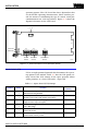
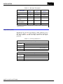
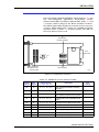
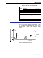
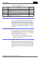
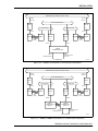
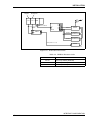
SECTION 3 - INSTALLATION
INTRODUCTION
This section explains special handling procedures, switch settings for each interface module, and how to install related
hardware. Complete the preliminary procedures in this section
before placing the INPPR01 into operation.
SPECIAL HANDLING
Plant Loop to Plant Loop Interface modules use Electrostatic
Sensitive (ESD) devices. Follow these handling procedures:
NOTE: Always use the Bailey Field Static Kit (P/N 1948385A1)
when working with interface modules. This kit connects the static
dissipative work surface and technician to the same ground point.
1. Keep the modules in their special anti-static bags until you
are ready to install them in the system. Save the bags for
future use.
2. Ground the anti-static bag before opening.
3. Verify that all devices connected to the modules are properly grounded before using them.
4. Avoid touching the circuitry when handling the module.
UNPACKING AND INSPECTION
1. Examine the PPT, LIM and BTM immediately to verify that
they have not been damaged in transit.
2. Notify the nearest Bailey Controls Sales Office of any such
damage.
3. File a claim for any damage with the transportation company that handled the shipment.
4. Use the original packing material and/or container to store
the modules.
5. Store the module in an environment of good air quality and
free from temperature and moisture extremes.
INPPT01 SWITCH SETTINGS
The INPPT01 consists of two circuit boards, a memory board
and a CPU board. The memory board has no user-configurable
I-E96-624A
INTRODUCTION
3-1
INSTALLATION
®
operating options. The CPU board has three dipswitches that
set the module operating characteristics. These switches provide the means of establishing the type of control, serial port
communication rate, and loop address. Figure 3-1 shows the
dipswitch locations on the CPU board.
JUMPERS
J1, J2, J3
J1 J2 J3
P1
P3
STOP SW2
U72
U73
U75
1 234567 8
1 234 5678
1 234 5
OPEN
OPEN
OPEN
P2
OPTION
SWITCH
BAUD RATE
SWITCH
DIAGNOSTICS
SWITCH
T00387A
RESET SW1
Figure 3-1. Switch Locations on the PPT (CPU board)
Option Switch (U72)
U72 is an eight position dipswitch that determines the operating options of the module. Table 3-1 lists the U72 option settings. Record the U72 settings in the space provided. When
setting switches, 0 = Closed (on) and 1 = Open (off).
Table 3-1. Option Switch (U72) Settings
Position
Setting
Function
1
0
1
ROM checksumming enabled
ROM checksumming disabled
2
0
1
RS-232-C port in DCE mode (direct connections)
RS-232-C port in DTE mode (modem connections)
3
0
1
Equipment select output de-energized
Equipment select output energized1
4
0
1
Port 1 option interface communication
Port 1 utility option2
5
0
1
Interface ID local3
Interface ID remote
6
0
1
Interface mode two-way control4
Interface mode one-way control
INPPT01 SWITCH SETTINGS
3-2
User
Setting
I-E96-624A
INSTALLATION
Table 3-1. Option Switch (U72) Settings (continued)
User
Setting
Position
Setting
Function
7
0
1
Don not initialize NVM
Initialize NVM
8
0
1
Primary/Secondary (one module of redundant pair is set to 0,
the other module is set to 1)
NOTES: 0 = Closed (on), 1 = Open (off)
1. A unique equipment select output can exist between the primary and secondary PPT. The equipment select output is digital output three
of a digital slave (IMDSM05 or IMDSO01/02/03/04).
2. Port 1 responds as DCE when it is configured as a utility port. Set switch position 4 = 1 if port 1 is not used as a communication interface.
3. Define only one interface as a local interface (position 5).
4. The following conditions apply when using two-way control (position 6 = 0):
a. The port 1 option defaults to interface communication (position 4 = 0).
b. The local INPPR01 uses port 0 as its command port and port 1 as its reply port.
c. The remote INPPR01 uses port 1 as its command port and port 0 as its reply port.
d. Both the local and remote interface must have a loop address of 0 (U75).
Serial Port Communication Rate (U73)
U73 is an eight pole dipswitch that sets the serial port communication rate. The communication rate directly affects data
throughput. Refer to Table 3-2 for communication rates. Table
3-3 lists message throughput for different point types. Record
the U73 setting in the space provided.
Table 3-2. Serial Port Communication Rate (U73)
Switch Position
User Setting
Baud Rate
1
Port 0
2 3 4
5
Port 1
6 7 8
0
0
0
0
0
0
0
0
50
1
0
0
0
1
0
0
0
75
0
1
0
0
0
1
0
0
110
1
1
0
0
1
1
0
0
134.5
0
0
1
0
0
0
1
0
150
1
0
1
0
1
0
1
0
300
0
1
1
0
0
1
1
0
600
1
1
1
0
1
1
1
0
1200
0
0
0
1
0
0
0
1
1800
1
0
0
1
1
0
0
1
2000
0
1
0
1
0
1
0
1
2400
1
1
0
1
1
1
0
1
3600
0
0
1
1
0
0
1
1
4800
1
0
1
1
1
0
1
1
7200
0
1
1
1
0
1
1
1
9600
1
1
1
1
1
1
1
1
19200
1
Port 0
2 3 4
5
Port 1
6 7 8
NOTE: 0 = Closed (on), 1 = Open (off)
I-E96-624A
INPPT01 SWITCH SETTINGS
3-3
INSTALLATION
®
Table 3-3. Message Throughput
Number of
Bytes
Time per
Point1
Points per
Second
Station
19
10.4 msec
96
Analog
8
4.7 msec
214
Digital
5
3.1 msec
322
Remote Control Memory (RCM)
7
4.1 msec
241
Remote Manual Set
Constant (RMSC)
7
4.1 msec
241
Device Driver
7
4.1 msec
241
Point Type
1. These figures are based on the calculated throughput of the various Exception Report data types
(at 19200 baud). Regardless of communication rate, the software overhead is approximately 0.5
millisecond per point.
Loop Address (U75)
Dipswitch U75 sets the loop address. Valid addresses are 0
through 31. Table 3-4 shows examples of switch settings for
the loop address. Record the loop address in the space
provided.
Table 3-4. U75 Loop Addresses
Example Settings
Address
Example
Switch Position
1
2
3
4
5
Binary Value
16 8
4
2
1
0
0
0
0
0
0
9
0
1
0
0
1
26
1
1
0
1
0
Switch Position
1
2
3
4
5
Binary Value
16 8
4
2
1
User Setting
User
Address
NOTE: 0 = Closed (on), 1 = Open (off)
INPPT01 SWITCH SETTINGS
3-4
I-E96-624A
INSTALLATION
INLIM03 SWITCH SETTINGS
The Loop Interface Module (INLIM03), shown in Figure 3-2, has
two user-configurable dipswitches: Event/Error Counter
Address Switch SW1 and Address Switch SW2. Tables 3-5 and
3-6 list the switch settings for the Event and Error Counters.
The LIM faceplate LEDs display the contents of the event/error
counters. Switch SW2 poles 1 and 2 are CLOSED for normal
operation. Refer to Table 3-7 for SW2 settings. The LIM can
have any address from 1 to 63.
S1
EVENT/ERROR
COUNTER ADDRESS
P1
P3
1 23 45 67 8
XU4
EDGE
CONNECTORS
OPEN
1 23 45 67 8
OPEN
P4 CONNECTOR
RIBBON CABLE
ATTACHES HERE
P2
S2
NODE ADDRESS
T00403A
Figure 3-2. LIM Switch Locations
Table 3-5. LIM Event Counter Addresses (SW1)
Counter
Hex
Address Address
I-E96-624A
Switch Position
1 2 3 4 5 6 7 8
Description
48
30
0 0 1 1 0 0 0 0
Total messages transmitted, including
forwarding.
49
31
0 0 1 1 0 0 0 1
Transmit retries.
50
32
0 0 1 1 0 0 1 0
Composite BTM Receive/Transmit, 4 bits
each. Receive is viewed at the top LED.
51
33
0 0 1 1 0 0 1 1
Messages taken from the BTM transmit
buffer.
52
34
0 0 1 1 0 1 0 0
Messages stored in BTM receive buffer.
53
35
0 0 1 1 0 1 0 1
Interrupt Requests (IRQs) sent by BTM.
54
36
0 0 1 1 0 1 1 0
High Priority (HP) messages transmitted.
55
37
0 0 1 1 0 1 1 1
High Priority messages received.
56
38
0 0 1 1 1 0 0 0
Commands issued by the BTM.
57
39
0 0 1 1 1 0 0 1
Missed BTM transmit requests.
User
Setting
INLIM03 SWITCH SETTINGS
3-5
INSTALLATION
®
Table 3-5. LIM Event Counter Addresses (SW1)
Counter
Hex
Address Address
Switch Position
1 2 3 4 5 6 7 8
(continued)
Description
58
3A
0 0 1 1 1 0 1 0
Spurious Non-Maskable Interrupts (NMI)
caused by address present.
59
3B
0 0 1 1 1 0 1 1
HEY (request for an interrupt; generated
by BTM) message sent.
60
3C
0 0 1 1 1 1 0 0
Messages discarded when the destination
is off-line.
61
3D
0 0 1 1 1 1 0 1
HEY time expirations.
62
3E
0 0 1 1 1 1 1 0
Passes through the IDLE level
(2 bytes wide).
User
Setting
NOTE: 0 = Closed (on), 1 = Open (off)
Table 3-6. LIM Error Counter Addresses (SW1)
Counter
Hex
Address Address
Switch Position
1 2 3 4 5 6 7 8
Description
64
40
0 1 0 0 0 0 0 0
Composite error count developed every
handshake period - the summation of all
other error counters.
65
41
0 1 0 0 0 0 0 1
Unresolved NMI interrupts.
66
42
0 1 0 0 0 0 1 0
Unresolved IRQ interrupts.
67
43
0 1 0 0 0 0 1 1
Unresolved timer interrupts.
68
44
0 1 0 0 0 1 0 0
Unused.
69
45
0 1 0 0 0 1 0 1
Queue overflows.
70
46
0 1 0 0 0 1 1 0
Unresolved BTM IRQs.
71
47
0 1 0 0 0 1 1 1
Sequence errors.
72
48
0 1 0 0 1 0 0 0
Header CRC/OVRN errors.
73
49
0 1 0 0 1 0 0 1
Data CRC/OVRN errors.
74
4A
0 1 0 0 1 0 1 0
Messages developing data CRC errors on
route to destination.
75
4B
0 1 0 0 1 0 1 1
Transmission failures.
76
4C
0 1 0 0 1 1 0 0
Watchdog timer expirations.
77
4D
0 1 0 0 1 1 0 1
Data length errors.
78
4E
0 1 0 0 1 1 1 0
Loop - 1 Receive (RCV) failure.
79
4F
0 1 0 0 1 1 1 1
Loop - 2 Receive failures.
80
50
0 1 0 1 0 0 0 0
Loop - 1 Transmit (TX) failure.
81
51
0 1 0 1 0 0 0 1
Loop - 2 Transmit failures.
User
Setting
NOTE: 0 = Closed (on), 1 = Open (off)
INLIM03 SWITCH SETTINGS
3-6
I-E96-624A
INSTALLATION
Table 3-7. LIM Node Address Setting (SW2)
Example Settings
Address
Example
Switch Position
1
2
3
4
5
6
7
8
Binary Value
128 64 32 16 8
4
2
1
1
0
0
0
0
0
0
0
1
9
0
0
0
0
1
0
0
1
63
0
0
1
1
1
1
1
1
2
3
4
User Setting
User
Address
Switch Position
1
5
6
7
8
Binary Value
128 64 32 16 8
4
2
1
NOTE: 0 = Closed (on), 1 = Open (off)
INBTM01 SWITCH SETTINGS
The Bus Transfer Module (INBTM01), shown in Figure 3-3, has
one user-configured dipswitch (SW1). SW1 enables module
diagnostics. Refer to Table 3-8 and set SW1 for normal
operation.
P1
P3
1
5
EDGE
CONNECTORS
OPEN
RESET
SWITCH
P2
SW1
OPTION SWITCH
T00401A
Figure 3-3. BTM Switch (SW1) Location
I-E96-624A
INBTM01 SWITCH SETTINGS
3-7
INSTALLATION
®
Table 3-8. BTM Options (SW1)
Switch Position
1 2 3 4 5
Function
0 0 0 0 0
Normal operation.
0 0 0 1 0
Normal BTM operation without catastrophic error checking (for Test Purposes ONLY).
0 0 1 0 0
RAM test mode. If Status LED turns red, the module has failed the test.
0 0 1 1 0
ROM test mode. If Status LED turns red, the module has failed the test.
0 1 0 0 0
Execute Interrupt Request (IRQ) LIM handshake diagnostic. Used in
combination with the LIM off-line diagnostics.
User Setting
NOTE: 0 = Closed (on), 1 = Open (off)
TERMINATION UNIT (MODULE) CONFIGURATION
Two of the interface modules (INLIM03, INPPT01) require termination. The INPPT01 terminates with the NTMF01 or
NIMF01/NIMF02. The INLIM03 terminates with the NTCL01 or
NICL01. Appendices A through D contain disphunt configuration information. Figure 3-4 shows a diagram of the NTMF01
and NTCL01 in a redundant installation. Figure 3-5 shows a
diagram of the NIMF01/NIMF02 and NICL01 in a redundant
installation.
NTMF01/NIMF01/NIMF02 Configuration
The TMF and IMF provide the INPPT01 with two RS-232-C
ports. Configure these ports to operate as DTE, DCE or diagnostic terminal. Refer to Figures A-1, A-2, and A-3 for NTMF01
dipshunt configurations. Refer to Figures C-1, C-2, and C-3 for
NIMF01/NIMF02 dipshunt configurations.
NOTE: You must use the NIMF01 and NIMF02 when using termination modules to terminate a redundant interface. Non-redundant
interfaces need only the NIMF01.
ONE-WAY CONTROL
Configure port 0 on the local and remote interfaces to act as
DTE. One local INPPR01 can communicate with up to 32
remote interfaces in the one-way control mode. Additional
communication equipment such as a modem network, radio
link or microwave link is required when interfacing multiple
remotes. The user supplies any additional equipment that is
needed.
TERMINATION UNIT (MODULE) CONFIGURATION
3-8
I-E96-624A
INSTALLATION
COMMUNICATION HIGHWAY (PLANT LOOP)
TWINAX
OR COAX
TWINAX
OR COAX
SLAVE EXPANDER BUS
NTCL01
NTCL01
P1
MODULE BUS
P1
MODULE BUS
NKLS03
NKLS03
P3
P3
INLIM03
INBTM01
INPPT01
INPPT01
P3
P3
DMA
CABLE
NKTU01
INLIM03
INBTM01
DMA
CABLE
NKTU01
P1
P3
NTMF01
TERMINATION UNIT
PORT 1
COMMUNICATIONS
OR UTILITY
PORT 0
COMMUNICATIONS
TO OTHER PPR
T00419A
Figure 3-4. NTMF01 and NTCL01 in a Redundant Installation
COMMUNICATION HIGHWAY (PLANT LOOP)
TWINAX
OR COAX
TWINAX
OR COAX
SLAVE EXPANDER BUS
NICL01
NICL01
P1
MODULE BUS
P1
MODULE BUS
NKLS04
NKLS04
P3
P3
INLIM03
INBTM01
INPPT01
INPPT01
P3
P3
DMA
CABLE
NKTM01
INLIM03
INBTM01
DMA
CABLE
NKTM01
P1
P1
NIMF01
TERMINATION J2
MODULE
NIMF02
J3 TERMINATION
MODULE
PORT 0
COMMUNICATIONS
PORT 1
COMMUNICATIONS
OR UTILITY
TO OTHER PPR
T00420A
Figure 3-5. NIMF01/NIMF02 and NICL01 in a Redundant Installation
I-E96-624A
TERMINATION UNIT (MODULE) CONFIGURATION
3-9
INSTALLATION
®
When directly connecting only one remote interface in one-way
control, set port 0 on the local interface to act as a DTE. Set
port 0 on the remote interface to act as DCE.
NOTE: Always configure port 1 as a utility port if it is not used as an
interface communication port. The PPT option switch (U72) position
4 must be set to 0 (utility option). Port 1 will always act as a DCE in
this configuration.
TWO-WAY CONTROL
The interface requires both serial communication ports in the
two-way control mode. Connect port 0 of the local Plant Loop to
port 0 of the remote Plant Loop. Connect port 1 of local Plant
Loop to port 1 of the remote Plant Loop.
Configure the termination unit to act as DTE to enable the
Plant Loop to Plant Loop Transfer Module to communicate with
DCE (i.e, a modem). Configure the termination unit to act as
DCE to enable the PPT to communicate with DTE (i.e., a terminal). Figure A-4 shows how the termination dipshunt configuration directs the RS-232-C signals.
NTCL01/NICL01 Configuration
The TCL and ICL provide the INLIM03 with Plant Loop termination. The user has the option of using Twinax or Coax cable to
connect the interface to the Plant Loop. Tables B-3 (NTCL01)
and D-3 (NICL01) show the jumper settings for twinax and
coax cables. Set the jumpers accordingly for your application.
NOTE: For complete cable and TU/TM installation information, refer
to the Termination Unit Manuall (I-E93-911).
INSTALLING THE INTERFACE MODULES
If the switch settings on the interface modules are complete,
they are ready to be installed in the Module Mounting Unit
(MMU).
Installing the INPPT01
WARNING
Disconnect power before installing dipshunts for slave modules on the MMU backplane (slave expander bus). Failure to do
so could result in severe or fatal shock.
AVERTISSEMENT
Couper l'alimentation avant d'installer les dipshunts sur la
plaque arrlere du chassis de montage de modules (MMU).
Toute negligence a cet egard constitue un risque de choc pouvant entrainer des blessures graves, voire moretlles.
INSTALLING THE INTERFACE MODULES
3 - 10
I-E96-624A
INSTALLATION
To install the PPT:
1. Verify the PPT slot assignment in the MMU.
a. If you are installing redundant PPTs, install a 24 pin
disphunt in the Slave Expander Bus socket between the
slot used by the primary PPT and the slot used by the secondary PPT. Both PPTs must reside on the same Slave
Expander Bus.
b. Each PPT must reside on its own module bus.
2. Attach the hooded end of the cable (NTKU01 for the
NTMF01; NKTM01 for the NIMF01 and NIMF02) to the MMU
backplane cable connector opening for the PPT. The other end
of the cable attaches to the termination unit or backplane of
the Termination Mounting Unit (NTMU01).
3. Guide the top and bottom edges of the circuit card along
the top and bottom rails of MMU.
4. Slide the module into the slot; push the module until the
front panel is flush with the top and bottom of the MMU frame.
5. Turn the two captive latches a half turn to lock the module
in place.
Installing the INLIM03 and INBTM01
The LIM and BTM should be installed as a pair in adjacent
slots. To install the LIM/BTM:
1. Verify the MMU slot assignments for the modules. If you
are installing redundant LIM/BTM pairs, each BTM must be
installed on the module bus that belongs to its related PPT.
2. Attach the hooded end of the cable (NKLS03 for NTCL01;
NKLS04 for the NICL01) to the MMU backplane cable connector opening for the LIM. The other end of the cable attaches to
the termination unit or TMU backplane.
3. Connect one end of the Bailey supplied ribbon cable (DMA
cable) to the P4 connector on the LIM. Connect the other end of
the DMA cable to the P4 connector on the BTM (see Figures 3-2
and 3-3).
4. Guide the top and bottom edges of both circuit cards along
the top and bottom rails of adjacent slots in the MMU.
5. Slide the modules into the slot; push the module until the
front panels are flush with the top and bottom of the MMU
frame.
I-E96-624A
INSTALLING THE INTERFACE MODULES
3 - 11
INSTALLATION
®
6. Turn the two captive latches a half turn to lock the module
in place.
INSTALLING A REDUNDANT INTERFACE
Installing a redundant interface requires an additional set of
INPPT01, INLIM03 and INBTM01 modules. Both PPT modules
must be on the same Slave Expander Bus, but reside on separate Module Bus. Each PPT has a pair of LIM/BTM modules on
a dedicated Module Bus.
Observe the following conditions when installing a redundant
interface:
1. U72 position 8 must be set to 0 on the primary PPT.
2. U72 position 8 must be set to 1 on the secondary PPT.
3. SW1 all positions must be set to 0 on both BTMs.
4. The slave expander bus of two adjacent MMUs (one on top
of the other) are connected with the expander bus extender
cable (Bailey P/N 1958502A0340).
5. The module bus between these MMUs are not connected.
Applications that use redundant communication equipment
may require additional hardware. Figure 3-6 shows a diagram
of the interface using the IMDSM05 to enable redundant transceivers. Function Code 130 provides the software the PPT
needs to enable the transceivers. Voltage levels and polarities
of enable signals to transceivers and other communication
equipment may vary. Refer to the applicable user manual when
connecting this equipment to the IMDSM05, IMDSO01/02/
03/04 Digital Slave Module.
INTERFACE CONFIGURATION
The user must configure the PPT with the proper function
codes before it can be placed into service. The PPT configuration determines interface operating characteristics such as
time synchronization, serial communication rate, node definition, point definitions and general execution characteristics.
Table 3-9 lists the function codes used by the INPPR01. Refer
to the Function Code Application Manual (I-E93-900-20) for
information about the function codes in Table 3-9.
INSTALLING A REDUNDANT INTERFACE
3 - 12
I-E96-624A
INSTALLATION
PRIMARY
PPT
SECONDARY
PPT
DSM05
A1
NKTU01 CABLES
A2
P1
A3
A4
NTDI01
P1
–
+
–
+
–
+
–
+
SELECT
ANTENNA
SWITCH
ENABLE
PRIMARY
TRANSCEIVER
ENABLE
REDUNDANT
TRANSCEIVER
NTMF01
P3
RS232 (LINES 1-5, 8, 20)
MODEM
T00421A
Figure 3-6. Redundant Transceiver
Table 3-9. INPPR01 Function Codes
Function Code
I-E96-624A
Title
FC 127
Plant Loop Gateway Node Map
FC 130
Plant Loop Gateway Executive
FC 131
Plant Loop Gateway Point Definition
INTERFACE CONFIGURATION
3 - 13
®