1
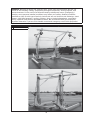
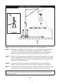
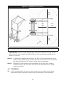
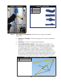
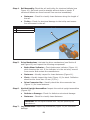
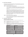
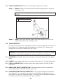
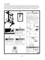
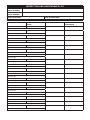
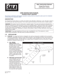
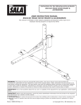
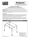
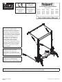
EN795: 1996
Class B
The Ultimate in Fall Protection
CE Type Test
CE Production Quality Control
No. 0086
BSI Product Services
P.O. Box 6221, Kitemark Court
Davy Avenue
Milton Keynes
MK1 9EP UK
No. 0086
BSI Product Services
P.O. Box 6221, Kitemark Court
Davy Avenue
Milton Keynes
MK1 9EP UK
C-Frame Rail Fall Arrest System
Model Numbers:
8517700
8517701
8517702
8517703
8517704
8517705
8517706
8517707
8517708
8517709
8517710
8517711
8517712
8517713
8530035
8530111
8530115
8530119
8530205
8530212
8530213
8530223
8530225
8530235
8530246
8530262
8530274
8530317
8530319
8530354
8530414
8530446
8530471
8530505
User Instruction Manual
WARNING: This product is part
of a fall arrest system. These
instructions must be provided to all
users and rescuers (see Section 9
Terminology) using this equipment.
The user must read and understand
these instructions before assembling
or using this equipment. The user
must follow the manufacturer’s
instructions for each component
of the system. Manufacturer’s
instructions must be followed for
proper use and maintenance of this
equipment. Alterations or misuse of
this equipment, or failure to follow
instructions, may result in serious
injury or death.
IMPORTANT: Before using this
equipment record the product
identification information from
the ID label in the ‘Inspection and
Maintenance Log’ at the back of this
manual.
IMPORTANT: If you have questions
on the use, care, application, or
suitability for use of this safety
equipment, contact Capital Safety.
EMPLOYEE TRAINING: This manual is intended to meet industry standards, including OSHA, ANSI Z359.1, and CE
EN795 and should be used as part of an employee training program as required by OSHA.
FORM NO: 5902343
REV: B
© Copyright 2013, Capital Safety
DESCRIPTION
C-Frame Rail Fall Arrest System with two trolleys for moveable fall arrest protection.
1.0
1.1
APPLICATIONS
PURPOSE: Personal Protective Equipment against falls from a height.
The C-Frame Rail Fall Arrest System (C-Frame FAS) with Fall Protection combines
easy access to elevated work areas with fall protection from the ground for the
duration of the work being performed. The system includes a height-adjustable
horizontal rail and two trolleys that can be moved to any position along the rail.
The trolleys serve as attachment points for the anchorage of a Personal FallArrest System (PFAS). The system can be moved by hand, by a forklift or towed
by a maintenance vehicle when equipped with proper accessories.
1.2
LIMITATIONS: The following application limitations must be considered before
using this product. Failure to observe product limitations could result in serious
injury or death.
A. ASSEMBLY: The rail system must be assembled in accordance with the
requirements stated in the Assembly Instructions Manual for this product
(PN 5902343).
B. CAPACITY: The maximum working load for this product is two persons with
a combined weight of 310 lbs. (141 kg) per person.
C. PERSONAL FALL ARREST SYSTEMS: Personal fall arrest systems used with
the C-Frame FAS must meet applicable state and federal regulations, or CE
regulations, and the requirements stated in section 4.3.
D. PHYSICAL AND ENVIRONMENTAL HAZARDS: Use of this equipment in
areas with physical or environmental hazards may require that additional
precautions be taken to reduce the possibility of damage to this equipment
or injury to the user. Hazards may include, but are not limited to: high heat
(welding or metal cutting), acid or caustic chemicals, corrosive environments
such as exposure to seawater, high voltage power lines, explosive or toxic
gases, moving machinery or sharp edges. Contact DBI-SALA if you have
questions about the application of this equipment in areas where physical or
environmental hazards are present.
E. TRAINING: This equipment is to be assembled, installed and used by
persons who have been trained in its correct application and use.
1.3
Refer to national standards, including the ANSI Z359 family of standards .0,
.1, .2, .3, and .4, local, state, and OSHA requirements, and CE standards
where applicable, for more information on the application of this and associated
equipment.
WARNING: Do not alter or intentionally misuse this equipment.
2
WARNING: Working at height has inherent risks. Some risks are noted here but are not
limited to the following: falling, suspension/prolonged suspension, striking objects, and
unconsciousness. In the event of a fall arrest and/or subsequent rescue (emergency)
situation, some personal medical conditions may affect your safety. Medical conditions
identified as risky for this type of activity include but are not limited to the following: heart
disease, high blood pressure, vertigo, epilepsy, drug or alcohol dependence, psychiatric
illness, impaired limb function and balance issues. We recommend that your employer/
physician determine if you are fit to handle normal and emergency use of this equipment.
Figure 1 - C-Frame Rail Fall Arrest System
A
SRL Attachment Point
A
A
3
2.0
SYSTEM REQUIREMENTS
2.1
COMPATIBILITY OF COMPONENTS: DBI-SALA equipment is designed for
use with DBI-SALA approved components and subsystems only. Substitutions
or replacements made with non-approved components or subsystems may
jeopardize compatibility of equipment and may effect the safety and reliability of
the complete system.
2.2
COMPATIBILITY OF CONNECTORS: Connectors are considered to be
compatible with connecting elements when they have been designed to work
together in such a way that their sizes and shapes do not cause their gate
mechanisms to inadvertently open regardless of how they become oriented.
Contact DBI-SALA if you have any questions about compatibility. Connectors
(hooks, carabiners, and D-rings) must be capable of supporting at least 5,000
lbs. (22.2kN). Connectors must be compatible with the anchorage or other
system components.
Do not use equipment that is not compatible. Non-compatible connectors may
unintentionally disengage (see Figure 6). Connectors must be compatible in size,
shape, and strength. Self-locking snap hooks and carabiners are required by
ANSI Z359.1 and OSHA.
2.3
CONNECTIONS: Only use self-locking snap hooks and carabiners with3this
equipment. Only use connectors that are suitable to each application. Ensure all
connections are compatible in size, shape and strength. Do not use equipment
that is not compatible. Ensure all connectors are fully closed and locked.
Figure 2 - Unintentional Disengagement (Rollout)
If the connecting element to which a snap hook (shown) or carabiner attaches
is undersized or irregular in shape, a situation could occur where the connecting
element applies a force to the gate of the snap hook or carabiner. This force may
cause the gate (of either a self-locking or a non-locking snap hook) to open, allowing
the snap hook or carabiner to disengage from the connecting point.
Small ring or
other noncompatibly
shaped element
1.FORCE IS APPLIED TO THE SNAP
HOOK.
2. THE GATE PRESSES AGAINST THE
CONNECTING RING
4
3. THE GATE OPENS ALLOWING THE
SNAP HOOK TO SLIP OFF
DBI-SALA connectors (snap hooks and carabiners) are designed to be used only
as specified in each product’s user instructions. See Figure 3 for inappropriate
connections. DBI-SALA snap hooks and carabiners should not be connected:
A. To a D-ring to which another connector is attached.
B. In a manner that would result in a load on the gate.
NOTE: Large throat snap hooks should not be connected to standard size D-rings or
similar objects which will result in a load on the gate if the hook or D-ring twists or
rotates. Large throat snap hooks are designed for use on fixed structural elements
such as rebar or cross members that are not shaped in a way that can capture the
gate of the hook
C. In a false engagement, where features that protrude from the snap hook or
carabiner catch on the anchor, and without visual confirmation seems to be
fully engaged to the anchor point.
D. To each other.
E. Directly to webbing or rope lanyard or tieback (unless the manufacturer’s
instructions for both the lanyard and connector specifically allows such a
connection).
F. To any object which is shaped or dimensioned such that the snap hook or
carabiner will not close and lock, or that roll-out could occur.
Figure 3 - Inappropriate Connections
5
3.0
OPERATION AND USE
WARNING: Consult DBI-SALA when using this equipment in combination with components
or subsystems other than those described in this manual. Some subsystem and component
combinations may interfere with the operation of this equipment. Use caution when using this
equipment around moving machinery, electrical hazards, chemical hazards, and sharp edges.
3.1
BEFORE EACH USE: Inspect this equipment carefully to ensure it is in good
working condition. Check for worn or damaged parts. Ensure all parts are present
and secure. Check the entire system for damage and corrosion. See section
5.0 for further inspection details. Do not use if inspection reveals an unsafe
condition.
3.2
PLANNING: Plan your system and how it will function before starting your work.
Consider all factors that affect your safety during use. Some important points to
consider when planning your system are:
A. HAZARD EVALUATION: Evaluate job site hazards prior to starting work.
Consult applicable OSHA (or CE) and industry standards for guidelines and
regulatory requirements on issues such as personal fall arrest systems
(PFAS).
B. WORK SITE GEOMETRY: The use of the FSHRS must be consistent with the
geometric requirements stated in the associated manufacturer’s instruction
manuals. Check for obstructions or sharp edges in the work path. Avoid
working where the user may swing and hit an object, or where lines may
cross or tangle with that of another worker.
C. RESCUE: When using this equipment, the employer must have a rescue plan
and the means at hand to implement it and communicate that plan to users,
authorized persons, and rescuers.
D.
3.3
AFTER A FALL: Any equipment which has been subjected to the forces
of arresting a fall or exhibits damage consistent with the effect of fall arrest
forces as described in section 5, must be removed from service immediately
and destroyed by the user, the rescuer, or an authorized person.
REQUIREMENTS FOR PERSONAL FALL ARREST SYSTEMS (PFAS): PFAS
used with the FSHRS must meet applicable OSHA requirements.
•
The PFAS should be rigged to minimize any potential free fall and never allow
a free fall greater than 6 ft. (1.8 m). The PFAS used with this equipment
are required to include a full body harness as the body support component.
PFASs that incorporate full body harnesses must maintain fall arrest forces
below 1,800 lbs. (8.0 kN) and arrest the fall within 42 in. (1.1 m). Body
belts, unless incorporated into a full body harness, are not allowed for use
with this equipment. A typical PFAS includes a full body harness, connecting
subsystem or component (self retracting lifeline or shock absorbing lanyard),
and the necessary connectors to couple the system together.
•
PFAS may only be attached to the two FSHRS trolleys which move along the
rail. See Figure 1 (A).
6
WARNING: Read and follow manufacturer’s instructions for the personal fall arrest equipment
selected for use with the C-Frame FAS.
IMPORTANT: Body belts are not allowed for free fall situations. Body belts increase the risk of
injury during fall arrest in comparison to a full body harness. Limited suspension time and the
potential for improperly wearing a body belt may result in added danger to the user’s health.
3.4
TRAINING: It is the responsibility of the user to assure they are familiar with
these instructions, and are trained in the correct care and use of this equipment.
User must also be aware of the operating characteristics, application limits, and
the consequences of improper use of this equipment.
IMPORTANT: Training must be conducted without exposing the trainee to a fall hazard.
Training should be repeated on a periodic basis.
3.5
PROCEDURE FOR USE OF THE RAIL SYSTEM:
Figure 4 - Procedure for Use (1 of 3)
5FT to 9FT
(1.5m to 3m)
above work surface
2
2
2
3
7
1
Figure 5 - Procedure for Use (2 of 3)
4
MIN
5 FT (1.5m)
MAX
9 FT (3m)
above work
surface
6 FT
(1.8m)
MAX
6 FT
(1.8m)
C
L
Step 1.
Move the unit 1 to 3 feet (0.3-1m) away from work area/object.
Step 2:
Adjust the rail height to be 5 to 9 feet (1.5- 3m) above the work surface
(1, Figure 4). Rail height is adjusted by cranking the drive handle (2,
Figure 4). Clockwise rotation of the drive handle will increase rail height;
counterclockwise rotation of the drive handle will reduce rail height.
Step 3:
Push the unit into position so that the rail is close to the center of the work
area to maximize the safe work area and reduce the chances of a potential
fall. Wheels and jacks (3, Figure 4) must be positioned over a stable, level
surface or leveled with blocks.
Step 4:
Lower the jacks down and apply light pressure by just contacting the
surface. Lock the wheels. Readjust rail height if necessary (see Step 2).
Step 5:
If applicable, pull down the tag line to connect to the SRL (4, Figure 5; SRL
not provided). Use a full body harness to safely access the work area.
NOTE: The SRL line must not drag or bend over a leading edge while accessing the
work area. To eliminate that problem reposition the unit. Follow the SRL manufacturer’s
instructions carefully.
8
Figure 6 - Procedure for Use (3 of 3)
MAX
6 FT
(1.8m)
MAX
6 FT
(1.8m)
MAX
6 FT
(1.8m)
MAX
6 FT
(1.8m)
5
IMPORTANT: follow the safe working area instruction carefully. If using an SRL more than 10
feet in length carefully follow the safe working area guidelines as shown in Figure 6.
IMPORTANT: follow the safe working area instruction carefully. If using an SRL
more than 10 feet in length carefully follow the safe working area guidelines as
shown in Figure 6.
Step 6:
If applicable, transfer the tag line to the SRL on the working anchor point
trolley. Follow guidelines for the safe working area carefully. Do not exceed
the safe working area (5, Figure 6) under any circumstances.
Step 7:
Maximum of two operators can be attached to the unit, each using an
individual trolley. No more than one person can be attached to a single
trolley at anytime.
4.0
4.1
TRAINING
It is the responsibility of users to make certain they are familiar with these
instructions and are trained in the correct care and use of this equipment.
9
5.0 INSPECTION
MAINTENANCE/INSPECTION SAFETY:
1. Read, understand and follow the User Manual and signs on the equipment before using,
maintaining or inspecting the equipment. Equipment must have a complete inspection
performed during setup and before first use.
2. Follow the inspection procedure contained in this of any other applicable the manual and
use the inspection form(s) to document the results.
3. Keep instructional and safety labels clean and legible at all times. Clean or replace as
required. See Section 7 for label information and part numbers.
4. Remove the equipment from service if a problem is found during the inspection using a
lockout/tagout procedure. Repairs must be done by an authorized repair depot or the
factory for service center.
WARNING: If theC-Frame Rail Fall Arrest System (C-Frame FAS) has been subject to impact
forces from fall arrest, it must be immediately removed from service and inspected. If the
C-Frame FAS fails to pass inspection, do not use. The equipment must be repaired by an
authorized service center.
IMPORTANT: Extreme working condition (harsh environment, prolonged use, etc.) may
require increased frequency of inspections.
5.1 VISUAL INSPECTION:
A complete visual inspection should be performed on the C-Frame FAS equipment
you are using prior to the operation. The following items should be checked, and
result recorded on the “Inspection and Maintenance Log” in at the back of this
manual.
Step 1.
Labels: Check that all labels are clean and legible. Clean the labels
if any are dirty using mild soap and damp cloth. Replace if any are
illegible (Refer to Section 7 for a listing of all labels).
Step 2.
Turnbuckle/Cable Assemblies: Inspect turnbuckles and cables:
•
Turnbuckles - Inspect turnbuckles (Figure 7) for damage and
proper adjustment.
•
Cables - Check cable assemblies for slack. Cables must be
tight enough to apply slight pressure on the unit. DO NOT
OVERTIGHTEN. Inspect cables for kinks, cuts, crushed sections,
burned areas, or other flaws (see Figure 8).
10
Figure 7 - Turnbuckle
Step 3.
Figure 8 - Cable Flaws
A
Kinked Wire Rope
B
Broken Wires
C
Bird-Caging
D
Welding Splatter
Rail Support Assemblies: Inspect the rail support assemblies
(Figure 9):
•
Defects or Damage - Check rail supports for structural defects or
damage.
•
Fasteners - Check for visually loose fasteners.
•
Overload Detection Gusset - This gusset is an indicator of a
previous fall or misuse/abuse. These gussets are located on each
rail support assembly (see Figure 9). Inspect the gussets visually
for straightness and to ensure there is no visible deformation
or bend; indicating an incident. Please ensure the proper M.A.F.
device is used for this product and read all labels (see Section 7)
prior to use. This gussets not only provide visual indication of a fall
or misuse but also provide protection against damage to the other
C-Frame FAS components and reduces costly repairs to the unit.
Figure 9 - Rail Support Assembly Inspection
A
Gusset
B
Fasteners
A
B
11
Step 4.
Rail Assembly: Check the rail and trolley for structural defects (see
Figure 10). Rail track must be straight without dents or bends. If
structural defects are found remove from service immediately.
•
Fasteners - Check for visually loose fasteners along the length of
the rail.
•
Trolley - Check for structural damage to the trolley and ensure
free movement in the rail.
Figure 10 -Rail Assembly Inspection
A
Rail
B
Trolley
A
B
Step 5.
Step 6.
Drive Mechanism: Lubricate the drive mechanisms (see Section 6
and Figure 16) and inspect the following components:
•
Brake Wear Indicator - Check brake wear indicator (Figure 11)
while lowering the unit. If the indicator is in the red area, remove
from service and contact the manufacturer.
•
Fasteners - Visually inspect for loose fasteners (Figure 11).
•
Chain - Visually inspect the chain (Figure 11) for slack. Deflection
should not be more than 13 mm (1/2 in.).
•
Drive Connector Bar - Visually check the drive connector bar
(Figure 11) for loose fasteners.
Vertical Upright Assemblies: Inspect the vertical upright assemblies
(Figure 12):
•
Defects or Damage - Check for defects or structural damage.
•
Fasteners - Check for visually loose fasteners.
IMPORTANT: Do not adjust threaded rods. They are preset by the
manufacturer.
Step 7.
Leg Assemblies: Inspect leg assemblies (Figure 12) for structural
damage.
12
Figure 11 - Drive Mechanism Inspection
A
Brake Wear Indicator
B
Fasteners
C
Chain
D
Drive Connector Bar
C
A
B
D
B
Figure 12 - Vertical Upright Assembly & Leg Assembly Inspection
A
Vertical Upright
Assembly
B
Threaded Rod
C
Leg Assembly
A
C
A
B
C
13
5.2 FUNCTIONAL INSPECTION:
A functional check should be performed on the C-Frame FAS prior to every use.
The following functional tests should be done; and the results recorded on the
“Inspection and Maintenance Log”.
Step 1.
System Operation and Adjustments:
The C-Frame FAS contains operational parts that include pulleys and/
or rollers (Figure 13 ). These parts must be carefully checked for chips,
cracks, or worn areas that can cause malfunction during operation of
the system.
Make sure that all the adjustment points are in full functional
condition. This may include parts that contain pins, bolts, tri-screws,
and jacks. There are also mechanical adjustments which may include
adjustable legs, sleeves, adjustable sliding legs, brackets and chain.
These areas must be kept clean from debris and corrosion for proper
functional use. If any part of the system that includes all listed items
above becomes damaged contact your Capital Safety representative
for parts and/or service.
Step 2.
SRL and other Accessory Inspection:
Refer to the manufacturer’s user manual or instructional material for
proper functional inspection procedures for SRLs and accessories not
covered by this manual.
5.3
QUARTERLY INSPECTION:
DETAILED INSPECTION POINTS:
Inspect the following inspection points on a quarterly basis (see Figure 14):
Step 1.
Corrosion: Inspect the entire unit for corrosion. If there is corrosion,
please consult the manufacturer for advisement.
Step 2.
Fasteners: Check all fasteners using a minimum of 20 N.m (15
ft.lbs) of torque. Unless otherwise specified, loose fasteners must be
tightened to 34 N.m (25 ft.lbs). Refer to the following drawings to
locate all fasteners:
Component:
Drawing #:
Vertical Upright Assembly
26373, 26374
Drive Base Assembly
26392
Drive Assembly
26375, 26389
Rail Support Assembly
20558
Wheels, Swivels, and Brakes
26174, 26178, 26366, 24989
Fasteners must be checked and tightened to the following torques:
Bolt Size and Grade:
Torque Setting:
1/2 inch, Grade 5
30-35 ft-lbs (40-48 Nm)
1/2 inch, Grade 8
35-40 ft-lbs (48-54 Nm)
5/8 inch, Grade 8
35-40 ft-lbs (48-54 Nm)
14
Figure 13 - Roller Inspection
A
Roller
A
A
A
Figure 14 - Detailed Inspection Points
A
Drive
B
Drive Base
C
Carriage Assembly
D
Leg Assembly
C
A
B
D
15
5.4
YEARLY INSPECTION: Perform the following inspections annually:
Step 1.
Wheels: Check and lubricate with wheel bearing grease as required
(see Figure 15).
IMPORTANT: Do not overtighten wheel axle bolts. Wheels must rotate freely
by hand.
Figure 15 - Wheel Bearings
A
Bearings
A
Step 2.
6.0
Chain: Check and lubricate chains with light lubricant or WD-40 as
required (see Section 6 and Figure 16).
MAINTENANCE
At regular intervals perform a detailed inspection of the equipment and document
the results in the Inspection and Maintenance Log (Section 10). Remove the
equipment from service if deficiencies are found.
WARNING: Do not make alterations or additions to this equipment without prior written
consent from Capital Safety. (Only the equipment manufacturer, or persons or entities
authorized in writing by the manufacturer, can make repairs to this equipment.)
6.1
CLEANING: Periodically clean the rail system using mild detergent and a damp
cloth.
6.2
LABELS: Clean labels and replace as needed. (See Section 7 for label examples.)
6.3
CHAIN LUBRICATION: Lubricate chains with light lubricant like WD-40 (See
Figure 16).
6.4
BRAKE AND DRIVE LUBRICATION: Lubricate brake and drive components
with a light lubricant like WD-40 (See Figure 16).
6.5
SYNCHRONIZING DRIVE CONNECTOR: If the synchronizing drive connector
(see Figure 17) is removed for any reason, including during maintenance, it is
critical NOT to crank the individual drives. This will cause an imbalanced height of
the trolley rail which can cause serious injury or death
16
Figure 16 - Lubrication
Figure 17 - Synchronizing Drive Connector
17
7.0 LABELS
The following labels must be securely attached to the C-Frame FAS and fully legible.
Proper maintenance of the labels must be established by the operator/entrant to keep
system use safe. If labels are damaged the operator/entrant must enforce a lock-out/
tag-out procedure. New labels are available from the local dealer or manufacturer.
F
A
DANGER
2x
4x
D
C
A
ELECTROCUTION
HAZARD
E
WATCH FOR OVERHEAD
POWER LINES
B
Pt#: 16399
G
F
B
C
WARNING
MAXIMUM LIFT CAPACITY 5000 Lbs / 22kN
DO NOT REMOVE THIS LABEL. FULLY
RETRACT OR ROTATE JACK BEFORE
TOWING. ENGAGE LOCKING PIN ON SWIVEL
JACK BEFORE TOWING OR USING JACK.
BLOCKS USED TO INCREASE HEIGHT CAN
CAUSE INSTABILITY AND MAY CAUSE
INJURY OR DEATH.
Pt# 18723 Rev.01
D
E
WARNING
WARNING
Ensure the leg screws / jacks are in contact
with the surface. To prevent instability,
screw legs down to contact surface and
crank the handle an extra 5 times,
approximately one (1) inch of the screw
leg. If the surface is uneven adjust
accordingly.
This product is approved for use with
retractable devices and shock absorbers
with a MAXIMUM ARRESTING FORCE
(M.A.F.) RATING OF 900 lb (4 kN) OR
LESS. Retractable devices and shock
absorbers must be installed, maintained
and used according to the manufacturer’s
instructions.
Pt# 13818
Pt# 8524261 Rev.03
G
18
8.0
SPECIFICATIONS
Working Load:
Maximum of two persons with a combined weight of
310 lbs. (141 kg) per person.
Materials and Construction
General Construction:
Finish (Aluminum):
Hardware Material:
9.0
Welded Steel/Aluminum
Yellow Powder Coat
Zinc Plated
TERMINOLOGY
Authorized Person: A person assigned by the employer to perform duties at a location where the person will be exposed to a fall hazard (otherwise referred to as “user”
for the purpose of these instructions).
Rescuer: Person or persons other than the rescue subject acting to perform an assisted rescue by operation of a rescue system.
Certified Anchorage: An anchorage for fall arrest, positioning, restraint, or rescue
systems that a qualified person certifies to be capable of supporting the potential fall
forces that could be encountered during a fall or that meet the criteria for a certified
anchorage prescribed in this standard.
Qualified Person: A person with a recognized degree or professional certificate and
with extensive knowledge, training, and experience in the fall protection and rescue
field who is capable of designing, analyzing, evaluating and specifying fall protection
and rescue systems to the extent required by this standard.
Competent Person: One who is capable of identifying existing and predictable hazards in the surroundings or working conditions which are unsanitary, hazardous, or
dangerous to employees, and who has authorization to take prompt corrective measures to eliminate them.
19
INSPECTION AND MAINTENANCE LOG
SERIAL NUMBER:
MODEL NUMBER:
DATE PURCHASED:
INSPECTION DATE
Approved By:
Approved By:
Approved By:
Approved By:
Approved By:
Approved By:
Approved By:
Approved By:
Approved By:
Approved By:
Approved By:
Approved By:
Approved By:
Approved By:
Approved By:
Approved By:
Approved By:
Approved By:
DATE OF FIRST USE:
INSPECTION ITEMS
NOTED
CORRECTIVE ACTION
MAINTENANCE
PERFORMED
LIMITED LIFETIME WARRANTY
Garantie limitée à vie
Warranty to End User: CAPITAL SAFETY warrants to the original end user (“End User”) that its
products are free from defects in materials and workmanship under normal use and service. This
warranty extends for the lifetime of the product from the date the product is purchased by the
End User, in new and unused condition, from a CAPITAL SAFETY authorised distributor. CAPITAL
SAFETY’S entire liability to End User and End User’s exclusive remedy under this warranty is limited
to the repair or replacement in kind of any defective product within its lifetime (as CAPITAL SAFETY
in its sole discretion determines and deems appropriate). No oral or written information or advice
given by CAPITAL SAFETY, its distributors, directors, officers, agents or employees shall create
any different or additional warranties or in any way increase the scope of this warranty. CAPITAL
SAFETY will not accept liability for defects that are the result of product abuse, misuse, alteration
or modification, or for defects that are due to a failure to install, maintain, or use the product
in accordance with the manufacturer’s instructions. THIS WARRANTY IS THE ONLY WARRANTY
APPLICABLE TO OUR PRODUCTS AND IS IN LIEU OF ALL OTHER WARRANTIES AND LIABILITIES,
EXPRESSED OR IMPLIED.
Garantie de l’utilisateur final : CAPITAL SAFETY garantit à l’utilisateur final d’origine («
Utilisateur final ») que ses produits sont exempts de défauts de matériaux et de fabrication dans
des conditions d’utilisation et d’entretien normales. Cette garantie s’étend pendant toute la durée
de vie du produit à compter de la date d’achat du produit par l’Utilisateur final, comme produit
neuf et inutilisé, auprès d’un distributeur agréé. L’entière responsabilité de CAPITAL SAFETY envers
l’Utilisateur final et le recours exclusif de l’Utilisateur final dans le cadre de cette garantie se limite
à la réparation ou au remplacement en nature de tout produit défectueux pendant sa durée de
vie (si CAPITAL SAFETY, à sa seule discrétion, le juge nécessaire). Aucune information ni aucun
conseil, qu’ils soient oraux ou écrits, donnés par CAPITAL SAFETY, ses distributeurs, directeurs,
responsables, agents ou employés ne créera de garanties différentes ou supplémentaires
ni n’augmentera l’étendue de cette garantie. CAPITAL SAFETY n’assumera en aucun cas la
responsabilité de défauts résultant d’une utilisation abusive du produit, de sa mauvaise utilisation,
de son altération ou de sa modification, ou de défauts découlant du non-respect des instructions
du fabricant en matière d’installation, d’entretien ou de conditions d’utilisation. CETTE GARANTIE
EST LA SEULE GARANTIE APPLICABLE À NOS PRODUITS ET ELLE REMPLACE TOUTES LES AUTRES
GARANTIES ET RESPONSABILITÉS EXPRIMÉES OU IMPLICITES.
Garanzia di durata limitata
Lebenslange Garantie mit Einschränkung
Garanzia dell’utente finale: CAPITAL SAFETY garantisce all’utente finale originale (di seguito
“Utente finale”) che i suoi prodotti sono privi di difetti dei materiali e di fabbricazione se utilizzati
nelle normali condizioni d’uso e di servizio. La garanzia copre l’intera durata del prodotto dalla
data di acquisto del prodotto da parte dell’Utente finale come prodotto nuovo e mai usato da un
distributore autorizzato CAPITAL SAFETY. La responsabilità complessiva di CAPITAL SAFETY nei
confronti dell’Utente finale e il ricorso esclusivo dell’Utente finale ai sensi della presente garanzia
sono limitati alla riparazione o alla sostituzione in natura dei prodotti difettati entro la durata (così
come stabilita a propria esclusiva discrezione da CAPITAL SAFETY). Eventuali informazioni orali
o scritte o consigli forniti da CAPITAL SAFETY, dai suoi distributori, direttori, funzionari, agenti o
dipendenti non potranno in alcun modo dare origine a garanzie diverse o aggiuntive né potranno
ampliare l’ambito della presente garanzia. CAPITAL SAFETY non potrà essere ritenuta responsabile
dei difetti derivati da un cattivo o errato utilizzo del prodotto, da alterazioni o modifiche o da difetti
dovuti ai mancati installazione, manutenzione o uso del prodotto in conformità alle istruzioni del
produttore. LA PRESENTE GARANZIA È L’UNICA GARANZIA APPLICABILE AI NOSTRI PRODOTTI E
SOSTITUISCE QUALSIASI ALTRA GARANZIA E RESPONSABILITÀ, ESPRESSE O IMPLICITE.
Endbenutzer-Garantie: CAPITAL SAFETY garantiert dem ursprünglichen Endbenutzer
(„Endbenutzer“), dass seine Produkte unter normalem Gebrauch und Betrieb frei von Materialund Herstellungsfehlern sind. Diese Garantie erstreckt sich auf die Lebensdauer des Produkts
ab dem Datum, an dem der Endbenutzer das Produkt neu und ungebraucht von einem durch
CAPITAL SAFETY autorisierten Händler gekauft hat. Die gesamte Haftung von CAPITAL SAFETY dem
Endbenutzer gegenüber und der einzige Anspruch des Endbenutzers ist gemäß dieser Garantie
beschränkt auf die Reparatur oder den Ersatz von defekten Produkten innerhalb ihrer Lebensdauer
(eine Einschätzung diesbezüglich wird von CAPITAL SAFETY nach eigenem Ermessen durchgeführt).
Keine von CAPITAL SAFETY schriftlich oder mündlich an Händler, Vorstandsmitglieder,
Führungskräfte, Agenten oder Angestellte übergegebenen Informationen oder Hinweise ergeben
jegliche andere oder zusätzliche Gewährleistungen, noch erhöhen sie den Umfang dieser Garantie.
CAPITAL SAFETY schließt eine Haftung für Defekte aufgrund von unsachgemäßem Gebrauch,
Änderungen oder Modifikationen am Produkt sowie für Defekte, die darauf zurückzuführen sind,
dass das Produkt nicht gemäß der Anweisungen des Herstellers montiert, gewartet und verwendet
wurde, aus. DIESE GARANTIE IST DIE EINZIG GÜLTIGE GARANTIE FÜR UNSERE PRODUKTE
UND GILT ANSTELLE VON ALLEN ANDEREN GARANTIEN UND HAFTUNGSBEDINGUNGEN, SEI ES
AUSDRÜCKLICH ODER STILLSCHWEIGEND.
Garantía limitada de por vida
Garantía para el Usuario final: CAPITAL SAFETY garantiza al usuario final original (“Usuario
final”) que sus productos están libres de defectos en materiales y mano de obra bajo condiciones
normales de uso y servicio. Esta garantía abarca toda la vida útil del producto, desde la fecha
de compra del producto por parte del Usuario final, en estado nuevo y sin uso, a un distribuidor
autorizado de CAPITAL SAFETY. Toda la responsabilidad de CAPITAL SAFETY para con el Usuario
final y el recurso exclusivo del Usuario final en virtud de esta garantía, se limita a la reparación
o sustitución en especie de cualquier producto defectuoso dentro de su vida útil (como CAPITAL
SAFETY lo determine y estime conveniente a su sola discreción). Ninguna información oral o
escrita, o información dada por CAPITAL SAFETY, sus distribuidores, directores, técnicos, agentes o
empleados, creará ninguna garantía distinta o adicional, ni de alguna manera ampliará el alcance
de esta garantía. CAPITAL SAFETY no acepta responsabilidad por defectos que sean resultado
del abuso, mal uso, alteración o modificación del producto, ni por los defectos que se deban a
una instalación, mantenimiento o utilización que no esté de acuerdo con las instrucciones del
fabricante. ESTA GARANTÍA ES LA ÚNICA GARANTÍA APLICABLE A NUESTROS PRODUCTOS Y
SUSTITUYE A CUALQUIER OTRA GARANTÍA O RESPONSABILIDAD, EXPRESA O IMPLÍCITA.
GARANTIA DE VIDA ÚTIL
Garantia ao usuário final: a D B Industries, Inc., sob o nome comercial de CAPITAL SAFETY USA (“CAPITAL
SAFETY”) garante ao usuário final original (“Usuário Final”) que seus produtos estão livres de defeitos
nos materiais e mão de obra sob uso e serviço normais. A garantia se estende pela vida útil do produto a
partir da data de compra do produto pelo Usuário Final, em condições novas e sem uso, de um distribuidor
autorizado da CAPITAL SAFETY. Toda a responsabilidade da CAPITAL SAFETY perante o Usuário Final e o único
recurso do Usuário Final nos termos desta garantia estão limitados ao reparo em espécie do produto com
defeito dentro de sua vida útil (como a CAPITAL SAFETY, a seu exclusivo critério, determinar e considerar
apropriado). Nenhuma informação ou aconselhamento verbal ou por escrito dados pela CAPITAL SAFETY, seus
distribuidores, diretores, executivos, agentes ou funcionários criará alguma garantia diferente ou adicional
nem poderá, de modo algum, aumentar o alcance desta Garantia. A CAPITAL SAFETY não se responsabilizará
por defeitos que sejam o resultado de abuso, uso indevido, alteração ou modificação do produto, ou por
defeitos resultantes de falha na instalação, manutenção ou uso do produto de acordo com as instruções do
fabricante.
A GARANTIA DA CAPITAL SAFETY SE APLICA SOMENTE AO USUÁRIO FINAL. ESTA GARANTIA É A ÚNICA
APLICÁVEL A NOSSOS PRODUTOS E SUBSTITUI TODAS AS OUTRAS GARANTIAS E RESPONSABILIDADES,
EXPRESSAS OU IMPLÍCITAS. A CAPITAL SAFETY EXCLUI EXPRESSAMENTE E REFUTA QUAISQUER GARANTIAS
EXPLÍCITAS DE COMERCIABILIDADE OU ADEQUAÇÃO A DETERMINADO FIM, E NÃO SERÁ RESPONSÁVEL
POR DANOS INCIDENTES, PUNITIVOS OU CONSEQUENTES DE QUALQUER NATUREZA, INCLUINDO, ENTRE
OUTROS, LUCROS CESSANTES, PERDA DE RECEITA OU PRODUTIVIDADE, OU POR FERIMENTOS PESSOAIS
OU MORTE OU PERDA OU DANOS À PROPRIEDADE, SOB QUALQUER TEORIA DE RESPONSABILIDADE,
INCLUINDO, ENTRE OUTRAS, A TEORIA AQUILIANA, DE GARANTIA, DE RESPONSABILIDADE OBJETIVA, DE
ATO ILÍCITO (INCLUINDO NEGLIGÊNCIA) OU OUTRA JURÍDICA OU EQUITATIVA.
Garantia vitalícia limitada
Garantia de utilizador final: a CAPITAL SAFETY garante ao utilizador final original (“Utilizador
Final”) que os seus produtos estão isentos de defeitos de materiais e de fabrico ao abrigo de uma
utilização e serviço normal. Esta garantia prolonga-se pela duração da vida útil do produto desde
a data de aquisição do produto pelo Utilizador Final, em condição nova e não usada, junto de
um distribuidor autorizado da CAPITAL SAFETY. A responsabilidade integral da CAPITAL SAFETY
perante o Utilizador Final e o recurso exclusivo do Utilizador Final ao abrigo desta garantia está
limitado à reparação ou substituição de qualquer produto defeituoso no decorrer da sua vida útil
(consoante apropriado e determinado exclusivamente segundo o critério exclusivo da CAPITAL
SAFETY). Nenhuma informação escrita ou oral ou conselho fornecido pela CAPITAL SAFETY, seus
distribuidores, directores, representantes, agentes ou funcionários irá criar garantias diferentes
ou adicionais ou de qualquer forma aumentará o âmbito desta garantia. A CAPITAL SAFETY não
aceitará responsabilidade por defeitos resultantes de abuso, utilização incorrecta, alteração
ou modificação, ou por defeitos do produto que resultem de um incumprimento de instalação,
manutenção ou utilização do produto de acordo com as instruções do fabricante. ESTA GARANTIA
É A ÚNICA GARANTIA APLICÁVEL AOS NOSSOS PRODUTOS E EXISTE EM DETRIMENTO DE
QUAISQUER OUTRAS GARANTIAS E RESPONSABILIDADES, EXPRESSAS OU IMPLÍCITAS.
The Ultimate in Fall Protection
CSG USA & Latin America
3833 SALA Way
Red Wing, MN 55066-5005
Distributed by Engineered Fall Protection
Email: [email protected]
Web: www.engineeredfallprotection.com
PH: 314-492-4422 | FAX: 800-570-5584
I S O
9001