1
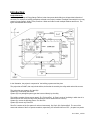
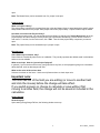
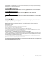
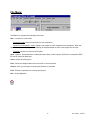
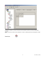
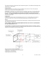
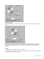
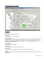
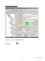
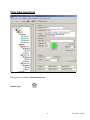
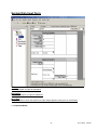
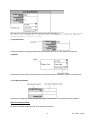
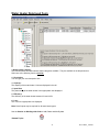
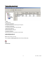
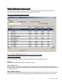
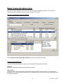
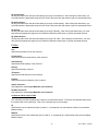
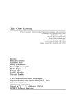
USER MANUAL
EnergyGauge FlaCom 2001
Version FLCCSB 1.22
Florida Solar Energy Center
1679 Clearlake Road
Cocoa, Florida 32922
1
FLCCSBV1_22UM1
EnergyGauge FlaCom .................................................................................................................................... 3
Introduction .................................................................................................................................................... 4
Project Explorer............................................................................................................................................ 11
Working with Grids ...................................................................................................................................... 13
File Menu...................................................................................................................................................... 15
Edit Menu ..................................................................................................................................................... 16
View Menu ................................................................................................................................................... 17
Calculate Menu............................................................................................................................................. 18
Reports Menu ............................................................................................................................................... 19
Resources Menu ........................................................................................................................................... 20
Tools Menu................................................................................................................................................... 21
Window Menu .............................................................................................................................................. 22
Help Menu .................................................................................................................................................... 23
Project Data Input Form ............................................................................................................................... 24
Zone Data Input Form .................................................................................................................................. 28
Space Data Input Form ................................................................................................................................. 31
Wall Data Input Form................................................................................................................................... 33
Window Data Input Form............................................................................................................................. 39
Door Data Input Form .................................................................................................................................. 42
Roof Data Input Form................................................................................................................................... 43
Skylight Data Input Form ............................................................................................................................. 44
Floor Data Input Form.................................................................................................................................. 45
System Data Input Form............................................................................................................................... 46
Plant Data Input Form .................................................................................................................................. 49
Water Heater Data Input Form ..................................................................................................................... 51
External Lighting Data Input Form .............................................................................................................. 52
Piping Data Input Form ................................................................................................................................ 53
Master Fenestration Library Form................................................................................................................ 54
Master Materials Library Form .................................................................................................................... 56
Master Constructs Library Form .................................................................................................................. 58
Project Materials & Constructs Library Form .............................................................................................. 61
Project Fenestration Library Form................................................................................................................ 65
Florida Building Code .................................................................................................................................. 67
System Requirements ................................................................................................................................... 68
Registration and Support .............................................................................................................................. 69
2
FLCCSBV1_22UM1
EnergyGauge FlaCom
EnergyGauge FlaCom is the Energy Code compliance tool for Florida commercial buildings. It was developed by
the Florida Solar Energy Center. EnergyGauge FlaCom is a Windows-based product and will operate under most
Microsoft Windows® versions.
If you are a new user, it is recommended that you start with the introduction.
For the latest information, visit www.energygauge.com.
3
FLCCSBV1_22UM1
Introduction:
Project Hierarchy
A fundamental concept in EnergyGauge FlaCom is that it structures the building into a hierarchical collection of
elements. For example, a building (sometimes referred to as Project) consists of multiple Zones which in turn may
contain of many Spaces, Walls, Floors, Roofs etc. Walls can further contain multiple Windows and Doors. The
figure demonstrates the concept.
In the illustration, the project is composed of the building, systems and the plant.
The project has a PLANT, that may include chillers, boilers that is served by the utility and/or other fuel sources.
The project has two systems, Sy1 and Sy2
System Sy1 is served by the PLANT
System Sy2 is a packaged system type that is served directly by the utility.
The building consists of three zones namely, Zo1, Zo2 and Zo3. (A Zone is a unit of a building in which the air is
assumed to be well mixed and where the temperature can be assumed to be uniform).
System Sy1 serves the following Zones: Zo1 and Zo2
System Sy2 serves only Zone Zo3
Zone Zo1 consists of the five spaces of various sizes namely, Sp1, Sp2, Sp3, Sp4 and Sp5. The sum of the
areas and volumes of the five spaces constitute, respectively, the area and volume of Zo1. (A space is a portion
4
FLCCSBV1_22UM1
of a Zone having a distinct internal load characteristic, such as Lighting and Equipment loads.
Zone Zo1 has two exterior walls namely Zo1Wa1 (west) and Zo1Wa2 (north)
Zone Zo2 has two exterior walls Zo2Wa1 (north) and Zo2Wa2 (East) and a partition wall Zo2Wa3 that is next to
Zone Zo1.
The east wall Zo2Wa2 in zone Zo2 contains a window Zo2Wa2Wi1. The orientation of windows need not be
specified. It is inherited from the wall on which it is mounted.
Zone Zo3 has three exterior walls namely Zo3Wa1 (west), Zo3Wa2 (south) and Zo3Wa3 (east).
Zone Zo3 has two partition walls. One, Zo3Wa4 which is next to Zone Zo1 and another Zo3Wa5 that is next to
zone Zo2.
The south wall Zo3Wa2 in zone Zo3 contains a door Zo3Wa2Dr1. The orientation of door need not be specified. It
is inherited from the wall on which it is mounted.
Materials and Constructs - Introductory Concepts
Unlike prior DOS versions of FLaCom where choices for construct (or envelope types) were mostly limited to
prebuilt Wall or Roof types, EnergyGauge FLaCom gives the user virtually unlimited choices. First the software,
provides the user with an extensive list of constructs for walls, roofs, floors. Second, the user has the option of
creating their own constructs and using them repeatedly. Therefore, an understanding of the basics behind
constructs is crucial in being able to use the software effectively.
5
FLCCSBV1_22UM1
A building may contain several envelope units such as walls, roofs and floors.
Each envelope unit has associated dimensions (such as width and height) and a construct.
The construct specifies the physical make up of the envelope unit
More than one envelope unit can have the same construct. Therefore, once a construct is developed or included
in a project, it can be used to specify the make up of several envelope units that have this make up.
A construct consists of one or more layers that make up the construct, except for a simple construct where layers
do not exist and gross properties of the construct are used in the calculations
Each layer is a slice of the construct that has distinct characteristics that include the material it is made up of, a
thickness and framing factor (if any).
The aggregate of each property of the layers constitutes the overall property of the construct. For example the
sum of the thickness of the layers is the total thickness of the construct.
6
FLCCSBV1_22UM1
Each layer must be associated with a material that must exist prior to building a construct.
A material has specific detailed thermal properties such as conductivity, density, specific heat and thickness.
Alternatively, in lieu of these properties one can specifiy only the R-Value in which case the material is assumed
to be mass less.
For details on how to build constructs, see the section on Project Materials and Constructs
Project
What is a project?
A project is your building input containing components such as zones, walls etc. When saved, the file has an
extension .egc
How does one create a new project?
You can open a project using the 'New' tool button or from the 'File' > 'New' menu.
How does one open and existing project?
You can open a project using the 'Open' tool button or from the 'File' > 'Open' menu.
Templates
What is a template?
A template is a file with preset information that can be used as a starting point for a new project. Templates
contain preset project and resource information such as constructs, materials and fenestration Users may create
and save as many templates as they need, and choose any template to create a new Project. Creating new
projects from templates can save considerable time, especially if constructs, materials and fenestration that are
often used are saved in a template for repeated use. In addition, user can also set the default fenestrations
envelope constructs
How to create a template?
From the main menu, Click 'File' > 'New' >'Template'. Make your modifications and save it.
How to modify existing templates?
Click 'Open'. Then select a template (a file with .EGT extension) from the open dialog. Make your modifications
and save it.
How does one create a new project using Templates?
1. A template file must first exist. If not, create one. Or use the sample template provided with the software.
2. Click 'File' > 'New' > 'Project from Template'.
3. Select a template (a file with .EGT extension) from the open dialog.
3. This creates a new project based on the selected template.
How do I know if I have opened a template or a project file?.
A Project will have a Project Explorer (tree). No such explorer will appear when a template is opened. In
addition, the form layout will be significantly different for each. Figure below the layout that will appear when a
template is opened.
7
FLCCSBV1_22UM1
To modify Fenestrations in the template click 'Tmpl Fenestrations' button located on the right-handside. Make
your modifications. See the section on Project Fenestration Library for editing functions. An alternate access is
through the the main menu. Click 'Edit' > 'Template Fenestrations'.
To modify Materials and Constructs in the template click 'Tmpl Materials and Constructs' button located on the
right-handside. Make your modifications. See the section on Materials and Constructs Library for editing
functions. An alternate access is through the the main menu. Click 'Edit' > 'Template Materials and Constructs'.
To set or modify preferences, in the main menu click 'Edit' > 'Template Preferences'. and make your
modifications.
Master Library
What is the Master Library?
The Master Library contains extensive resources on materials, fenestration and constructs. It serves as a
repository from which you can draw into your individual project or template. Users cannot change information
contained in the master library.
How does one access the master library?
From the main Menu, Click 'Resources' --> 'Master Library' . Then click the library component you want to
8
FLCCSBV1_22UM1
open.
Note: The Master library can be accessed even if a project is not open
Project Library:
What is a Project Library?
The project library is similar to the master library but unlike the Master Library is associated with a specific project
and provides resources for the project. Each project has its own project library. Project Libraries may be edited.
How does one access the Project Library?
First, a project must be open. You can access the project library by selecting the "Project Resources" tab of the
project explorer and then clicking the library button you want access. Alternatively, you can access it from the
main menu. To do this, from the main menu, click 'Edit' . Then click the project library component you want to
open.
Note: The project library can be accessed only if a project is open
Miscellaneous:
Some fields may be inactive, why?
Some fields are intentionally kept inactive or uneditable. They usually represent the defaults used in calculations
and are not user-editable.
What are tool tips. How do I get tool tips displayed?
In general, if you hover the mouse on any (non grid) field on any form, a tool tip appears giving more information
about that field, such as data ranges and units.
What are the units of the various data.
Units are not written on the forms. Use the tool tip feature above to check input units.
Important note:
You must tab out of the field you are editing (or move to another field
and click the mouse) before the change will take effect.
If you switch screens or choose to calculate or save without first
moving to another field, the change will not be saved or included in the
calculation.
Getting Started
General Layout:
Upon starting EnergyGauge FlaCom, the following window comes up.
9
FLCCSBV1_22UM1
To create a new project click the 'New' tool button.
To open and work on an existing project, click the 'Open' tool button.
Alternatively, you can open an existing or new project from the 'File' menu.
If you require help, click on the 'Help Contents' button or use the 'Help' from the main menu
10
FLCCSBV1_22UM1
Project Explorer
When a project is opened, the project explorer (sometimes called building tree) appears. It is a hierarchical
representation of the entire building. It is through the project explorer that one navigates the various building
components. It is also used to add and delete various building components.
In general, the Project Explorer (tree) consists of nodes representing Collections and Components. Collections
are containers that appear 'bolded' and contain one or more components under them. Example: the 'Zones'
Collection contains one or more individual zones. A component represents a physical element of a building such
as wall, or door or window etc.
What are Collections?
A collection is a group of a particular type of component. All the components in a collection are of the same type.
For example, a collection of Zones only consists of individual zones.
What are individual components?
A component represents a single building element. One or more components of the same type together form a
collection.
Adding a component
To add any new component of a particular type first click (that is, select using the left mouse button) the
collection.
11
FLCCSBV1_22UM1
Then right-click on the selected collection.
Select the 'add' option from the pops-up menu.
A new component of that type will be added and the input data form will appear (usually) on the right-hand portion
of the screen.
Example: To add a new wall under Zone 1, first select the bolded 'Walls' under Zone 1. Keeping the cursor on the
'Walls', perform a right click, then select the 'Add New' option from pop up menu. This will add a new wall and the
data input form will show up on the right. You can then input your data on the data input form.
Selecting a component to edit
Just clicking on an individual component opens the data input form for that component, For example, clicking on
the component labeled 'Zone 1" opens the data input form for Zone 1.
Deleting a component
Selecting (using the left mouse button) an individual component node and then clicking the right mouse button
pops a menu from which the selected component can be deleted
Expanding and collapsing the project explorer tree
Click on the + or - sign on the tree node to expand or collapse the tree. Right-clicking on a selected node opens
a pop up menu with options to expand or collapse the tree.
Exceptions:
Certain nodes on the project explorer such as 'Plant', 'Water Heating', 'External Lighting' and 'Piping' are
Collections whose components are placed on a form grid in a table format. For example, click 'Water heating'.
An input data form containing a grid with all water heaters in the project will appear.
Copying and Pasting
You can copy any component of a building, such as, a Zone, Wall etc and paste it into the corresponding
collection. For example a 'Wall' can be copied and then pasted into any 'Walls' collection.
Steps to Copy and Paste
1) Select (using the mouse.) the component that is to be copied
2) Right-Click on the selected component. A popup menu appears.
3) Select the copy option in the popup menu. (The component is now placed in a Copy buffer indicated by the
label at the bottom of the Project Explorer)
4) Select (using the mouse) the corresponding Collection where you would like to paste the copied component.
For example, if you copied a Wall, select any 'Walls' collection.
5) Right-click on the selected collection. A popup menu appears.
6) Select the 'Paste' option in the popup menu. The component will be copied into the selected collection.
12
FLCCSBV1_22UM1
Working with Grids
Working with grids (or Data Tables). General Procedures
Grids (or data tables) are extensively used in EnergyGauge FlaCom. These spread-sheet like grids can display
large amounts of data in a concise fashion in addition to providing the ability to edit displayed data. They appear
on several forms, such as Project and Master libraries, 'Water Heating', 'External Lighting', 'Piping', 'Space' etc. A
clear understanding of how to work with Grids is critical in effectively using the software. The general actions that
the user is likely to perform with grid are described in this section.
A typical data grid
How do you add rows on a grid?
There are generally two ways to add rows to grids.
1) Select the grid (just click anywhere on the grid) using the mouse and then press the “Insert” key on the
keyboard. Follow instructions that appear.
2) Right-click the mouse over the grid and then select the ‘Add’ option from the Pop up menu. Follow
instructions that appear.
How do you delete a rows on a grid?
There are generally two ways to delete rows from a grids.
1) Select any cell on the row you want to delete using the mouse and then press the “Delete” key on the
keyboard. Follow instructions that appear.
2) Right-click on any cell on the row you want to delete on the grid and then select ‘Delete’ from the Pop up menu.
Follow instructions that appear.
How to select or move between cells on a grid ?
Use the mouse to click on a cell. Also, you can use the Tab key to move from cell to cell.
How do you edit individual Grid Cells?
There are several types of grid cells.
Cells with numeric or text data
These are cells where numeric or text data can be entered. Double-clicking the cell puts it in edit mode. Pressing
the F2 key also has the same effect. You can then enter the new value. To complete the edit, press the Enter key
13
FLCCSBV1_22UM1
on the keyboard or click elsewhere on the grid. If the cell is already active (as shown by a light focus rectangle),
just begin typing the new value to edit the cell.
Cells where
appears when selected
These cells usually require data from other dialogs. Click on the
appears when selected
Cells where
These cells require selection from the dropdown. Click on the
button and follow instructions that appear.
button and make your selection.
appears when selected
Cells where
Values in these cells can be changed up or down. Click on the up or down arrow depending on what you want to
do.
Cells where
or appear
These imply an unselected or Selected option. Values in these cells can be toggled by clicking on the cell, or
pressing your 'Space-Bar' key on your key board.
Note: Some grid cells may not allow any of the above. It is usually because the cells are temporarily or
permanently non-editable.
How do I sort grids:
Most grids can be sorted by clicking the appropriate column header.
To sort a single column, click on that column header.
Clicking a header on an already sorted column reverses the sort order and resorts.
You can sort multiple columns (up to three) by holding down the CTRL key and clicking on up to three column
headers one after another (while keeping then CTRL key down)
How do I manually or automatically (Auto size) resize Grid Columns widths
In general, double clicking on a column header will auto size the column width to the largest entry in that column.
To auto size all columns, double click the top left corner label (that is, the top left corner label which is the label
cell common to the column headers and row labels)
You can manually resize column widths by moving your mouse between column headers until a resize cursor
appears. Now hold the left mouse down and move left or right.
How do I manually resize Grid row heights
You can manually resize row height by moving your mouse between row labels until a resize cursor appears. Now
hold the left mouse down and move up or down.
14
FLCCSBV1_22UM1
File Menu:
The File menu consists of the following sub menus:
New - It consists of 3 sub menus.
Project(FL Code): Opens a new project for code compliance
Project From Template(FL Code): Opens a new project for code compliance from a template. When this
option is chosen, a dialog appears for selecting the template based on which a new project is to be open.
Template: Use this to create a new Template
Open - Opens a file selected from a subsequent open dialog. Either a project (.EGC) file or a template (.EGT)
file can be opened for data input.
Close - Closes an existing a file.
Save - Saves the changes made to the current file on to the hard disk.
Save as- Gives you the option of choosing the filename to save data.
Print - Prints the input data of a currently open project.
Exit - Closes application.
15
FLCCSBV1_22UM1
Edit Menu
The 'Edit' menu has the following sub menus
Project Preferences - This sub menu opens the dialog for settings defaults for the current project or template as
shown
You can set the default type for each envelope component. Any new envelope component you add to the project
will use these settings. You can change these setting at any time.
Project Materials and Constructs - This sub menu opens the Project Materials and Constructs Library for
editing
Project Fenestration - This sub menu opens the Project Fenestration Library for editing
Project Data - This sub menu opens the Project Data Input Form for editing.
16
FLCCSBV1_22UM1
View Menu
The 'View' menu contains the following sub menus.
Project Explorer: This sub menu shows or hides the Project Explorer when applicable
Status Bar: This sub menu displays an informational status bar at the bottom when checked.
DOE Outputs: Has the following sub menus
Last Design Run
Last Run
The calculation engine, DOE 2.1e, produces text outputs that can be viewed for possible errors, warnings and
caution. The above two sub menus are provided only to be used for debugging should the need arise.
17
FLCCSBV1_22UM1
Calculate Menu
The Calculate menu has the following sub menus
Error Check
For Method A. Checks errors for Method A calculation. Does not perform the calculation
For Method B. Checks errors for Method B calculation. Does not perform the calculation
Displays the data errors in the project. It usually consists of the component being error-checked, an error
message, possible cause, and possible resolution. It is recommended that an error check be performed before a
compliance calculation is run.
You can also check for errors by clicking the red 'Check' label at the bottom of the Project Explorer.
Nodes with errors appear in red. Hovering the mouse on the node with error displays a tool tip with the
error message.
Method A - Whole Building Calculation
Runs the Method A (or whole building) code calculation. This is a computer based annual energy performance
calculation. Under this method, energy performance is calculated for the entire building based on the envelope
and major energy-consuming systems specified in the design and simultaneously for a reference building of the
same configuration, but with reference features. Note that this runs and displays only the Whole building
compliance calculation. To get compliance for all components of the building using Method A, use the Reports
menu > Compliance Reports > All Method A - Whole building Performance
Method B - Envelope Performance
Runs the Method B (or component) code calculation. This is a computer based calculation methodology. Under
this method, each component of the building systems must meet minimum performance standards. Note that this
runs and displays only the Envelope compliance calculation. To get compliance for all components of the building
using Method B, use the Reports menu > Compliance Reports > All Method B - Component performance
Run DOE Simulation:
This runs an energy (not code compliance) calculation on the design building. It is not an option nor a requirement
for code compliance. However, its output may be of some use to the designer.
18
FLCCSBV1_22UM1
Reports Menu
Input Report: This produces a detailed report of the project inputs.
Compliance Reports has eight sub menus. They are:
All-Method A - Whole Building Perfromance: This produces a compliance of all building components
based on Method A.
All-Method B - Component Performance: produces a compliance of all building components based on
Method B.
Select Reports: allows user to choose reports to be printed
Note: In certain instances of renovation, addition or shell buildings, only some of the individual reports may be
required. For example, if only a system is being replaced, only the system report may be required. Check your
current energy code manual and local jurisdiction for specific requirements.
19
FLCCSBV1_22UM1
Resources Menu
Provides access to the following Master Library resources:
Fenestrations Displays the Master Library of Fenestrations
Materials: Displays the Master Library of Materials
Constructs: Displays the Master Library of Constructs
20
FLCCSBV1_22UM1
Tools Menu
The Tools menu has the following sub menus
Customize This menu allows the user to customize the Tool bars.
Options: This option allows the user to change the application user interface layout. Layout options include Tab
location and style.
Settings This allows the user to set, change or remove the default directory from which input files are initially
opened.
Convert Input file to Current Version: This allows users to update input files to the current version.
Repair corrupt file: In rare instances, the input file created by the user may get corrupted. The symptom is
usually a failure to open a sucessfully saved file. On such files, try this option to repair the files and then open.
DO NOT USE THIS OPTION ON FILES THAT OPEN SUCESSFULLY
21
FLCCSBV1_22UM1
Window Menu
The sub menus under the Window menu provide the user with the option of viewing multiple forms in several
formats.
Cascade: Reduces the size of open window and places them on top of each other
Tile Horizontal: All open windows are tiled horizontally.
Tile Vertical: All open windows are tiled horizontally.
Arrange icons: The window icons are minimized and are arranged at the bottom of the screen
Note: These menus are only for the visual convenience of the user. Window in this context does not refer to the
'Windows' or 'fenestrations' in a building.
22
FLCCSBV1_22UM1
Help Menu
Sub Menus provides access to the Help system.
Contents: This sub menu opens the contents dialog of the Help system. The user can navigate to any topic from
the contents. In addition the user can print any topic displayed or book from the contents dialog.
Index: Opens the searchable Index dialog of the help system
Search: for Help on: Opens a key word search of the help system
About EnergyGauge:. Provides information about the installed version of EnergyGauge FlaCom
Important Note: Pressing the F1 key on your key board will provide context sensitive help
23
FLCCSBV1_22UM1
Project Data Input Form
Project Information Tab:
Description
Acronym:
A short description (up to 20 characters).
Title:
A fuller description (up to 50 characters)
Owner:
The building owner information
Location Info:
24
FLCCSBV1_22UM1
Address:
The address where the building is located. Two lines are available for this.
City:
State:
Zip:
Building Orientation (or Azimuth):
It is the orientation of the building relative to true north. It is expressed in degrees from 0 to 360 degrees. The default
is 0.0. Changing this angle has the effect of rotating the building about its z-axis (vertical axis). The default value
is 0 and usually does not require modification. Clicking will open the Azimuth Dial window. Azimuth (North = 0,
South = 180, West = 270, East = 90)
There are 3 ways to enter the value
i)Click on the minus
or plus button
to select the value and then click on OK
ii)Click on the E or W or N or S or NE or NW or SW or SE to enter the selected value and then click OK.
iii)Click on the wheel to select the desired value and then click OK.
NOTE: Orientation of Walls, Roofs and Floors are relative to the building orientation. Any value other
than zero for the building orientation will rotate all Walls, Roofs and Floors correspondingly during
calculation.
Permit No.:
The permit number, if any, obtained from your jurisdiction.
Jurisdiction:
It is the city and/or county with authority to issue your building permit.
25
FLCCSBV1_22UM1
Building Info
Type:
It is the building classification based on use class from the Type list.
Class:
The class building such as New or existing for which compliance is being calculated.
No of Storeys:
The number of the separate floors in this building project. The default is 1
Designer Tab:
Enter names of individuals and Registration as applicable.
Zone Assignment Tab:
26
FLCCSBV1_22UM1
For Method A compliance, all zones in the project must be assigned to systems by checking the appropriate
check box
A system can have more than one zone assigned to it. However, multiple systems cannot be assigned to a single
zone.
Related Topics
27
FLCCSBV1_22UM1
Zone Data Input Form
Zone Load Data
NOTE: The area and volume of the zone are automatically calculated by summing the individual values for the
spaces under the zone. This occurs any time a change is made to space dimensions or spaces are added or
deleted.
There is, however, a limitation on the per Zone Area and Volume thus calculated. Maximum Zone area is limited
to 100,000 SF and maximum Zone Volume is limited tp 1,000,000 CF. However, these can be overcome by
defining additional Zones or using the Zone Multiplier for multiple zones that are exactely the same.
Acronym:
A short description (of upto 20 characters)
Description:
Here a detailed description (of upto 50 characters)
Type:
It specifies the type of the zone
Conditioned: maintains zone air at desired conditions
Unconditioned: Zone is not conditioned.
Plenum: Zones that act as conduits for return air.
Dimensions:
Area not included in spaces [SF]:
28
FLCCSBV1_22UM1
This represents extraneous area that has not been included under spaces. This is added to the total space areas
under the zone. If none, set to 0
Number of Zones:
It specifies the number of such identical zones in the building as the current one. If two or more zones are
identical, use this entry rather that creating additional zones
Load Profile: By default each zone uses the load profile of the Building Type chosen on the Project Data Input
form. To set a zone to a different load profile, uncheck the 'Use building profile' check box and then select the
load profile. For example, the building type may be assembly, by may have a zone that serves as an office
located in it. The building type selected on the project form will be assembly, but the load profile selected for this
zone will be of type 'Office'.
Lighting Type:
It specifies the predominant type of overhead lighting used in the zone. Note that lighting power and type is
specified in the space forms. Select here the predominant lighting type of the spaces under this zone.
Source:
Specifies internal source type due to sources other than people, lights, or equipment. Note that the source rates
rate is specified in the space forms.
HOW TO HANDLE A PRE-EXISTING UNCONDITIONED ZONE THAT IS NOT PART OF YOUR DESIGN BUT
HAS YOUR ENVELOPE NEXT TO IT
In some instances, you may have to account for a zone that pre-exists and is not part of your design. Since the
calculation requires a physical zone whenever an adjacent envelope is specified next to it, the following procedure
suggests how to accomplish it with minimal input and effort.
Steps to account for an Zone that preexists.
1) Add a Zone. You may choose to label it as "PRE-EXIST"
2) Set the Zone to "Unconditioned"
3) Add a Space under this new Zone
29
FLCCSBV1_22UM1
4) Set Space category to 'Unlisted'
5) Set the width and height of the space equal to the width and height, respectively, of your adjacent wall.
6) Set the depth of the space to a minimum value, say 1 ft.
7) Set No of Task locations to zero.
8) Add a lighting to the space. Use mimiumal watts (equal to what is indicated by the Budget, or say 5 watts).
9) Set Control Type to Security Lighting.
10) Set No of Controls to Zero.
11) You can now set your adjacent wall next to this new PRE-EXIST zone
12) if you are running Method A, you will have to assign the PRE-EXIST zone to some system in you project. As
long the PRE-EXIST zone is set to 'Unconditioned', there will be no energy impact
Related Topics
30
FLCCSBV1_22UM1
Space Data Input Form
Acronym:
A short description (of upto 20 characters)
Description:
A detailed description (of upto 50 characters)
Category:
Select a space type from the list. For space type not listed select the one most representative from the list. This
is a key selection that will affect the lighting allowance.
Dimensions:
Width [ft]:
Depth [ft]:
Height [ft]:
Multiplier:
31
FLCCSBV1_22UM1
It is used to specify the number of identical such spaces. Use this input for spaces that are exactly the same,
instead of adding a new space under the zone.
NOTE: The area and volume of the zone to which the space belongs are automatically calculated by summing
the individual values for all spaces under the zone. This occurs any time a change is made to space dimensions
or spaces are added or deleted. There is, however, a limitation on the per Zone Area and Volume thus calculated.
Maximum Zone area is limited to 100,000 SF and maximum Zone Volume is limited tp 1,000,000 CF. Space
dimensions specified here should conform to this limitation.
Lighting:
Number of tasks: Number of separate tasks/activities in the space.
Type:
This field describes the various lighting types. They are available in the drop down box Click here for details.
Watt:
The lighting wattage.
Control:
This field describes the type of control used for the particular lighting.
No. CP:
This field shows the number of control points for the particular lighting.
See the section on Working With Grids to Add, Delete and Modify the Lighting data
Loads Tab:
For code calculations, the Loads tab on the Space form is provided for information only. Default values
are set by the program based on the space type selected. User is not allowed to make changes.
Related Topics
32
FLCCSBV1_22UM1
Wall Data Input Form
Wall info:
Acronym:
A short description (of upto 20 characters)
Description:
A detailed description (up to 50 characters)
Select Construct:
This allows selection of the construct (sometimes called wall type or envelope type) for the wall. Clicking this
button opens a list of all constructs in the Project. User can then select a construct for the wall from the list. If a
suitable construct is not available in the list, you must first add (or build) the construct in Project Resources
before being able to select that construct for the wall.
Dimensions:
Shape Type:
33
FLCCSBV1_22UM1
The shapes which are listed in the drop down box are:
Note that the required number of dimensions will become active and should be entered
i) Square
ii) Rectangle
iii) Triangle
iv) Semicircle
v) Trapezoid
34
FLCCSBV1_22UM1
vi) Rectangle with semicircle
vii) Rectangle with triangle
If the shape selected is a Rectangle with Triangle or Trapezoid then the user has to enter 3 dimensions in the
dimension boxes.
If the shape selected is a square then the user has to enter 1 dimension.
For rest of the shapes only 2 dimensions have to be specified.
Dimensions [ft]:
The required dimensions based on the particular shape selected.
Multiplier:
It is used to specify the total number of identical wall panels located in the same plane. If two or more walls are
identical, use this entry rather that adding more walls to your project.
Placement:
35
FLCCSBV1_22UM1
The figure above gives the general principles of determining the Tilt and Azimuth angles. An outward normal is
first drawn from the exterior side of the surface. An outward normal is a line that is perpendicular to the plane of
the surface in question.
The tilt angle is the angle made by the outward normal with the vertical axis as shown in figure.
The azimuth is the direction the surfaces faces. For vertical surfaces, it is simple to determine the direction. It is
simply the direction the outward normal faces. To obtain the direction for a non vertical surface, first project the
outward normal to the horizontal plane. The direction the projected line faces is the Azimuth, with North = 0, East
= 90, South = 180 and West = 270.
Tilt:
Surface tilt. Vertical = 90 (eg. Vertical Wall) ; Horizontal facing up = 0 (eg. Flat roof) ; Horizontal facing down =
180 (eg. floor). Click cell to set value. The following dialog opens
36
FLCCSBV1_22UM1
Orientation (Azimuth):
Surface orientation (North = 0, South = 180, West = 270, East = 90). Click cell to set value. The following dialog
opens.
NOTE: Orientation of Walls, Roofs and Floors are relative to the building orientation. Any value other
than zero for the building orientation will rotate all Walls, Roofs and Floors correspondingly during
calculation.
Location:
The explanation given here applies to Walls, Roofs and Floors
Exterior implies that the surface is exposed to the outside (eg. Exterior Walls, Exterior Roofs, Floor that are
raised above grade and exposed to the outside).
37
FLCCSBV1_22UM1
Underground implies that the surface is on or below ground (eg. basement walls, on-grade and below grade
floors).
Adjacent to another zone implies that the surface is adjacent to another previously defined zone (eg.
partition walls and ceiling between Storeys). In this, case the zone to which this is adjacent to must be selected
using the selection button.
The note below applies ONLY to version 1.21 and below.
Important Note:The Adjacent zone selected here must always be a previously defined zone in the project
hierarchy. It cannot be a succeeding zone in the project hierarchy. So the first zone in the project cannot have
adjacent surfaces defined. But the second zone in the project can have surfaces that is adjacent to the first zone.
However it cannot have surfaces defined that are adjacent to a third zone which comes after this one in the
hierarchy.
Begining Version 1.22, the above restriction does not apply and the user is not required order the zones as
above. The program automatically attempts to reorder zones as required and issues an error message when
circular references in adjacent envelopes are discovered. A circular reference is one in which, for example, an
envelope in Zone A is adjacent to Zone B, and another envelope in Zone B is adjacent to Zone A.
If the location above is adjacent to another zone, then the name of the adjacent zone must be selected by
clicking on the Select Adjacent Zone button
Miscellaneous:
The following are not user editable and are provided for information only. The defaults are set by the Application.
Gnd Refl:
is the solar reflectance of the ground.
Infl Coef:
is an infiltration flow coefficient used to compute the infiltration resulting from cracks in a wall.
Outside Emiss:
is the Emmissivity of the exterior side of the wall.
Inside Vis Refl:
is the fraction of light reflected by the interior side of the surface.
Inside Sol Abs:
is the fraction of radiation absorbed by the interior side of the surface. Radiation may fall on an interior surface
through fenestration placed on other surfaces (eg. Sunshine falling on floors through a window or skylight)
Related Topics
38
FLCCSBV1_22UM1
Window Data Input Form
Window info:
Acronym:
A short description (of upto 20 characters)
Description:
A detailed description (of upto 50 characters)
Select Glass Type:
This allows selection of the fenestration type for the window. Clicking this button opens a list of all fenestration in
the Project. User can then select a fenestration for the window from the list. If a suitable fenestration is not
available in the list, you must first add (or build) the fenestration to your Project Resources before being able to
select that fenestration for the window.
Frame Width [ft]:
It is the width of the window framing.
SetBack [ft]:
It is the distance that the window is recessed into the wall
Inside Vis Refl:
It is the amount of light reflected from the interior side of the window. Not user editable
Infl Coef:
It specifies an infiltration flow coefficient used to compute the infiltration resulting from cracks in the window. Not
user editable
39
FLCCSBV1_22UM1
Dimensions:
Similar to Wall Data Input Form
Shading:
Shading for windows is activated by checking the shading check box. A set of data input cells become visible
where shading parameters can be entered. Shading surfaces include, Overhangs, Left and Right Fins. Enter all
data that is applicable
The figure shown below is a basic representation of a window and shading as seen from outside. The dimensions
are labeled on the figure and defined below:
Overhang A [ft]
Distance from left window edge to left corner of overhang. Units are in feet, 0.0 is the default, and there are no
limits.
Overhang B [ft]
Distance from top of window to back edge of overhang. Units are in feet, 0.0 is the default, and there are no limits.
Overhang W [ft]
Width of overhang. Units are in feet, 0.0 is the default, and the range is 0.0 to no limits.
Overhang D [ft]
Depth of overhang. Units are in feet, 0.0 is the default, and the range is 0.0 to no limits.
40
FLCCSBV1_22UM1
Overhang Angle [deg]
Angle in degrees between overhang and window. When set at 90 degrees, the overhang is perpendicular to the
window; if less than 90 degrees, it is tilted downward; if greater than 90 degrees, it is tilted upward. The range is 0
to 180 degrees.
Left/Right Fin A [ft]
Distance from left/right window edge to fin back edge. Units are in feet, 0.0 is the default, and there are no limits.
Left/Right Fin B [ft]
Distance that top of fin is below top of window. Units are in feet, 0.0 is the default, and there are no limits.
Left/Right Fin H [ft]
Height of fin. Units are in feet, 0.0 is the default, and the range is 0.0 to no limits.
Left/Right Fin D [ft]
Depth of fin. Units are in feet, 0.0 is the default, and the range is 0.0 to no limits.
Related Topics
41
FLCCSBV1_22UM1
Door Data Input Form
Data inputs are very similar to the Wall Data Input Form
However data on placement and location etc. are not required.
Shading:
Shading for doors is activated by checking the shading check box. A set of data input cells become visible where
shading parameters can be entered. Enter all data that is applicable
For a detailed account of shading parameters see the Window Data Input Form
Related Topics
42
FLCCSBV1_22UM1
Roof Data Input Form
Data inputs are very similar to the Wall Data Input Form
Related Topics
43
FLCCSBV1_22UM1
Skylight Data Input Form
Skylight info:
Data inputs are similar to Window Data Input Form, except shading is not available for skylights
Related Topics
44
FLCCSBV1_22UM1
Floor Data Input Form
Data inputs are very similar to Wall Data Input Form
Related Topics
45
FLCCSBV1_22UM1
System Data Input Form
Acronym:
A short description (of upto 20 characters)
Description:
A detailed description (of upto 50 characters)
No of Units
Enter the number of such units (Use this to input multiple systems serving one or more Zones)
1. Component Name:
46
FLCCSBV1_22UM1
Here the type of the component (whether cooling,heating etc) is displayed. If a check box appears near
the name of the component, it indicates that the component is optional and user
decided whether to select it or not.
2. Input Parameter:
It shows the different required parameters (like capacity,EER, IPLV etc.) for the respective component.
3. Options:
It describes the option type for the component. Any sub-option may be selected by clicking on the sub option
4. Sub Option parameter
If parameter field appears next to a selected sub option. The the value of the parameter must be selected.
Steps for entering the data:
To select an optional component click on the check box to select it.
47
FLCCSBV1_22UM1
To enter a data click on the respective column. A pop up window will appear. Enter or select the value and then
click OK.
To choose a particular option in a component click on the radio button.
Related Topics
48
FLCCSBV1_22UM1
Plant Data Input Form
A plant is added or removed from the project by checking or unchecking the appropriate 'Use' check box. Data
that must be entered appears. Based on the plant selected, additional parameters that must be input appears in
the parameter grid below.
1. Type:
This column shows the type of equipment.
2. Equipment:
This column displays the name of the equipment.
3. Capacity:
Specifies the capacity of the selected equipment. The units in which the data is to be entered is also shown.
4. Quantity:
Specifies how many such equipment are installed.
5..Efficiency:
Specifies efficiency of the equipment. The units in which the data is to be entered is also shown.
6. IPLV:
Specifies Integrated Part Load Value, if required.
Based on the equipment selected, the parameter grid will appear. Appropriate data must be entered.
49
FLCCSBV1_22UM1
Related Topics
50
FLCCSBV1_22UM1
Water Heater Data Input Form
1. Water Heater Category:
This field describes the various Water Heater categories available. They are available in the drop down box.
Select one of the following from the pick list.
2. Description:
You can type your own description here.
3. Capacity:
The capacity of the water heater. Units are displayed in the cell.
4. Input Rate:
The power rating of the water heater in the appropriate units displayed.
5. Efficiency:
The efficiency of the water heater between 0% and 100%.
6. Loss:
The loss in the appropriate unit displayed.
Note: Not all inputs may be required for all water heater types
See the Section on Working with Grids to Add, Delete and Modify data
Related Topics
51
FLCCSBV1_22UM1
External Lighting Data Input Form
1. External Light Category:
External lighting category. Select one from the pick list.
2. Description:
You can type your own description or comment here.
3. Wattage
The power rating in watts.
4. Lin-ft or area or number of faces of exit signs:
Input depends on the category selected. Enter length or area or number of faces for exit signs. Required unit will
be shown.
See the section on Working with Grids to Add, Delete and Modify data
Related Topics
52
FLCCSBV1_22UM1
Piping Data Input Form
1. Type:
Piping application
2. Operating Temperature:
The operating temperature at which the pipe will operate.
3. Insulation Conductivity:
The conductivity of the insulation around the pipe.
4. Nominal Pipe Diameter:
Specifies the diameter of the pipe.
5. Insulation Thickness:
Specifies the thickness of the insulation around the pipe.
6. Check if Runout upto 2-in
Specific if the pipe is a runout.
Note: Units are shown on the form
See the section on Working with Grids to Add, Delete and Modify data
Related Topics
53
FLCCSBV1_22UM1
Master Fenestration Library Form
The master Fenestration Library is a list of over 150 Fenestration used in building construction. The serves as a
resources from which selected Fenestration can be inserted into the project
The user is not allowed to make any changes
See the section on Working with Grids to see how to size the grid
Layers:
Specifies number of glass layers in the fenestration (1 is single glass, 2 is double glass and so on).
UC:
Specifies thermal conductance.
SC:
Specifies the Shading Coefficient
SHGC:
54
FLCCSBV1_22UM1
Specifies the Solar Heat Gain Coefficient
Sol Trans:
Specifies the Solar Transmittance
VLT:
Specifies the visible light transmittance
Related Topics
55
FLCCSBV1_22UM1
Master Materials Library Form
The master Materials Library is a list of over 300 materials used in building construction. The serves as a
resources from which selected materials can be inserted into the project
The user is not allowed to make any changes
See the section on Working with Grids to see how to size and sort the grid
Viewing Selected materials:
You can view selected materials by using the short-list radio buttons provided on the form.
Show All:
Clicking this radio button will display all materials in the library
Show by Material Use:
Clicking this radio button will allow materials to be short-listed by general use of the material. After clicking this
radio button, you must also select the appropriate use category from the Combo box below the radio button to get
the requested short-list
Show by Material Category:
Clicking this radio button will allow materials to be short-listed by general type of the material. After clicking this
radio button, you must also select the appropriate type from the Combo box below the radio button to get the
56
FLCCSBV1_22UM1
requested short-list
Description:
Is the description about the material
Thick:
Specifies the thickness of the material in feet.
Conductivity:
Specifies the thermal conductivity of the material.
Density:
Specifies the material density.
Specific Heat:
Specifies the specific heat of the material.
Use:
Specifies the general use for the material
Category:
Specifies the material type.
Fixed Thickness:
Currently not used.
Use R-Val
Two possible specification for a material are possible:
1) Specify valid thickness and all thermal properties. In this case, valid conductivity, density and specific heat
must be specified and the' Use RVal' check box must be unchecked. This option is used for materials that are
likely to have mass effects or when these properties are accurately known. The program will use the thermal
properties and ignore the R-Value
2) For light and thin materials, or for those materials for which the thermal properties are not available, the second
option is to specify only the R-Value. In this case the 'Use R-Value' box must be checked. The program will
ignore the thermal properties, and use only the R-Value and treat the material as mass less.
R-Value:
Specifies the thermal resistance of the material.
The user is not allowed to make any changes
Related Topics
57
FLCCSBV1_22UM1
Master Constructs Library Form:
The master Constructs Library is a list of over 300 constructs used in building construction. The serves as a
resources from which selected constructs can be inserted into the project
The user is not allowed to make any changes
See the general section on Working with Grids to see how to size and sort the grid
Viewing Selected Constructs:
You can view selected materials by using the short-list radio buttons provided on the form.
Show All:
Clicking this radio button will display all materials in the library
Show by Use:
Clicking this radio button will allow the list to be short-listed by general use of the construct. After clicking this
radio button, you must also select the appropriate use category from the Combo box below the radio button to get
the requested short-list
58
FLCCSBV1_22UM1
By Conductance:
Clicking this radio button will allow short-listing by a range of conductance. After clicking this radio button, you
must also select the appropriate range from the Combo box below the radio button to get the requested short-list.
By Heat Capacity:
Clicking this radio button will allow short-listing by a range of heat capacity. After clicking this radio button, you
must also select the appropriate range from the Combo box below the radio button to get the requested short-list.
By Density:
Clicking this radio button will allow short-listing by a range of Density. After clicking this radio button, you must
also select the appropriate range from the Combo box below the radio button to get the requested short-list.
By Added R-Value:
Clicking this radio button will allow short-listing by a range of R-Value. After clicking this radio button, you must
also select the appropriate range from the Combo box below the radio button to get the requested short-list.
Fields:
Use:
Specifies the possible use for the construct.
Conductance:
Specifies the thermal conductance of the construct.
Heat Capacity:
Specifies the heat capacity of the construct.
Density:
Specifies the density construct
Thickness:
Specifies the total thickness of the construct
R-Value:
Specifies the thermal resistance of the construct.
Simple Construct :
See explanation under Project Materials and constructs
No-Mass Construct :
See explanation under Project Materials and constructs
Constructs Library Layers Table
This child table provides the details of the layers in the selected construct. The layers are specified starting from
the outside layer to the inside layer. That is, the outermost layer is the first layer.
ID
Specifies the Id of the material the layer is made of. It corresponds to a valid material number from the Master
Material Library.
Material
Specifies the name of the material the layer is made of. It corresponds to a valid material name from the Master
Material Library.
59
FLCCSBV1_22UM1
Thickness
Specifies the thickness of the layer. When a layer is added the thickness of the material as specified in the
material library is used. However, an overriding thickness can be entered here, in which case the original
thickness in the material library is ignored and the value entered here is used.
Framing Factor
Specifies the framing, if any, on the layer. Framing Factor is the ratio of the framing area on the layer to the total
area of the layer.
The user cannot make any changes to the Master library database.
Related Topics
60
FLCCSBV1_22UM1
Project Materials & Constructs Library Form
Constructs Tab:
The Project Constructs Library is very similar to the Master Constructs Library except that it is associated with a
specific Project that is currently open or created. This library stays with the Project and changes made here are
applicable only to the current project.
The user may make any modification as required
The following columns may be edited by the user
Construct Grid:
Constructs may be added or removed by following the general procedures for adding and deleting rows from
grids.
Simple Construct. Beginning version 1.22, the 'Simple Construct' option is available to the user when the user
decides to enter gross properties of the construct rather that through individual layers. Only when the 'Simple
contruct' is checked for a particular construct, all layers, if any, for that construct are ignored. The user will now be
able to enter the gross properties (Conductance, Heat capacity, Density and Thickness) for that construct in the
construct grid.
No Mass Construct. Beginning version 1.22, the 'No-Mass Construct' option is available to the user when the
user decides that the wall is too thin or too light for the thermal mass have any impact on compliance calculations.
When the 'No-Mass contruct' option is checked for a particular construct, only the U-Value is considered in the
calculation. This option should be used if most materials that make up the construct are defined only using R-
61
FLCCSBV1_22UM1
Value for the materials or if the gross thickness of the construct is less that an inch (0.084 ft). In general, use this
option if mass-related properties are not available for the gross construct or the materials that constitute the layers
of the construct.
User may change the entries under the 'Constructs' column of the grid. Type a name that makes most sense for
the construct.
All other fields in this grid are not editable, except when the construct is declared 'Simple' They are automatically
recalculated and updated based on changes to layers and or materials when 'Simple Construct' is unchecked.
Conductance:
Conductance may be entered if you check the Simple Construct option. Otherwise the field is non editable and is
automatically calculated from the layer data.
Heat Capacity
Heat Capacity may be entered if you check the Simple Construct option and uncheck the No-Mass construct
option. Otherwise the field is non editable and is automatically calculated from the layer data.
Density
Density may be entered if you check the Simple Construct option and uncheck the No-Mass construct option.
Otherwise the field is non editable and is automatically calculated from the layer data.
Thickness
Thickness may be entered if you check the Simple Construct option and uncheck the No-Mass construct option.
Otherwise the field is non editable and is automatically calculated from the layer data.
R-Value
This field is not editable and is calculated based on other inputs
NOTE: Constructs that may be problematic are flagged as shown for Construct No. 1011 above. If this construct
is used in a project envelope component, running Calculate > Error Check will provide error information possible
resolution.
Layer Gird:
Layers may be added or removed by following the general procedures for adding and deleting rows from grids.
User may change the material of any layer by clicking on the cell button that appears when any cell under the
material column in the layer grid is selected.
When a layer is added, the thickness defaults to the thickness of the material selected for the layer. User may
override the thickness by typing a different value.
User may change the framing factor by typing the desired value. Framing factor is the area-fraction of the
framing in a layer. That is, it is the ratio of the area of framing to the total area of the wall. It should be entered for
those layers mounted on framing. For example, insulation that is mounted on framing.
User may reorder the layers in the layer grid by holding left mouse button down on the label cell (the cells in the
left most column) of the layer to be moved, and dragging it up or down. A drag icon appears during the dragging
process.
See the section on Working with Grids to Add, Delete and Modify data
Materials Tab
The Project Materials Library is very similar to the Master Master Library except that it is associated with a
specific Project that is currently open or created. This library stays with the Project and changes made here are
62
FLCCSBV1_22UM1
applicable only to the current project.
The user may make any modification as required
Materials may be added, removed and changed by following the general procedures on working with grids.
All fields in the grid except 'Mat No' can be changed by the user.
Conductivity:
Specifies the thermal conductivity of the material.
Density:
Specifies the material density.
Specific Heat:
Specifies the specific heat of the material.
Thick:
Specifies the thickness of the material in feet.
Use R-Val
Two possible specification for a material are possible:
1) Specify valid thickness and all thermal properties. In this case, valid conductivity, density and specific heat
must be specified and the' Use RVal' check box must be unchecked. This option is used for materials that are
likely to have mass effects or when these properties are accurately known. The program will use the thermal
properties and ignore the R-Value
63
FLCCSBV1_22UM1
2) For light and thin materials, or for those materials for which the thermal properties are not available, the second
option is to specify only the R-Value. In this case the 'Use R-Value' box must be checked. The program will
ignore the thermal properties, and use only the R-Value and treat the material as massless.
R-Value:
Specifies the thermal resistance of the material.
Important Cautionary Note: It is critical to note that any change to the material properties, will affect the
properties of all constructs that use this material as a layer. In general changes to Project Library of materials,
constructs or fenestration, will propagate throughout the entire project which use this library component.
NOTE: Materials that may be problematic are flagged as shown for Material No. 7 above. If this material is used
in a construct that is then used in a project envelope component, running Calculate > Error Check will provide
error information possible resolution.
See the section on Working with Grids to Add, Delete and Modify data
Related Topics
64
FLCCSBV1_22UM1
Project Fenestration Library Form
The project fenestration library allows the user to add Fenestration to the project which can then be selected by a
project window or skylight as the fenestration type.
Fenestration options:
Two options are available to specify fenestration.
1) If the 'User Defined' Check Box is Unchecked, the program uses the Fenestration type specified in the 'Glass
Library Type' column. All properties for the glass are taken from the master fenestration library for the
corresponding glass type.
Values indicated in columns 'VLT', 'Panes', 'SC', 'Glass conductance' are those of the Glass Library Type.
2) If the 'User Defined check box is Checked, then the program uses the user input values of fenestration
properties. The properties uses 'VLT', 'Panes', 'SC', 'Glass Conductance', Inside Emmissivity' and Outside
Emmissivity' as input by the user. Columns under 'Glass Type', 'Spacer Type' are ignored.
Note: Frame conductance and absorptance are considered for both options
User defined
If checked, specifies that the fenestration properties that will be used are user defined, If not checked,
fenestration properties are taken from the master fenestration library. See options above.
Name
65
FLCCSBV1_22UM1
Specifies a name for the fenestration. User can type any convenient short description.
Glass Type
The glass type selected from the master library. Use the pull-down in this column to select the desired glass type
from the master fenestration library. The 'User Defined' check box must be unchecked to make an entry here
Spacer Type
Specifies the spacer type. Use the pull down in this column to change selection. If not known, set to 'User Library
Default'. The 'User Defined' check box must be unchecked to make an entry here
VLT
Specifies the Visible Light Transmittance. The 'User Defined' check box must be checked to make an entry here.
Frame Conductance
Specifies Frame conductance
Frame Absorptance
Specifies frame absorptance
Pane
Specifies the number of glass panes for a user defined fenestration.
SC
Specifies the shading coefficient of the glass panes for a user defined fenestration
Glass Conductance
Specifies the conductance of glass panes for a user defined fenestration
Inside Emmissivity
Specifies the number of glass panes for a user defined fenestration
Outside Emmissivity
Specifies the number of glass panes for a user defined fenestration
See the Section on Working with Grids to Add, Delete and Modify data
Related Topics
66
FLCCSBV1_22UM1
Florida Building Code:
The code manuals are copyrighted by a separate entity and must be ordered separately. For more information on
how to obtain code manuals, CDs, contact:
Southern Building Code Congress International, Inc.
900 Montclair Road
Birmingham, Alabama 35213-1206
USA.
Telephone: 1-888-447-2224
Web site: www.sbcci.org
Also, the following web site has links to online documentation and downloads (including forms) for the Florida Building
Code
www.floridabuilding.org/bc/
67
FLCCSBV1_22UM1
System Requirements:
To run EnergyGauge FlaCom, your system must meet the following minimum requirements:
- A minimum of 486 with a 66 Mhz processor (Pentium processor recommended)
- At least 20 MB of free hard-disk space (depending on installation type)
- Desktop Screen setting of 800 by 600 pixels or larger.
- Mouse
- CD-ROM drive
- Internet access (optional)
- Microsoft Windows 95/98/2000/Me:
8 MB of RAM minimum with Internet Explorer 5.0 or higher.
DCOM (included in the installation package for Windows 95/98/2000).
MDAC 2.6 (included in the installation package) or higher.
- Microsoft Windows NT 4.0 :
16 MB of RAM minimum with Internet Explorer 5.0 or higher.
Service Pack 3 or higher.
- Microsoft Windows XP Home Edition:
16 MB of RAM minimum
Based on your specific OS version and other software installed on your machine, it is possible that some conflicts
may arise. These have to resolved on a case-by-case basis. Please report any problem you encounter promptly
to EnergyGauge Technical Support office.
68
FLCCSBV1_22UM1
Registration and Support:
Registration:
EnergyGauge FLaCom should be registered either through the Internet or by mail after installation.
Technical Support:
Software Support - EnergyGauge/FlaCom is only the first of a suite of software products for
commercial building energy analysis to be developed by the Florida Solar Energy Center. Follow-up
versions will offer continuous improvement of features and customized results to meet user needs.
As the EnergyGauge Support Office receives questions they will try to post the answers on their
software support site http://www.energygauge.com
Training Support - Training in a variety of renewable energy and energy-efficiency subject areas
is available through the Florida Solar Energy Center at their Education & Training
page(http://www.fsec.ucf.edu/Ed/index.htm).
e-mail Support - You may contact the Energy Gauge Support Office by e-mail at
[email protected] Please include your phone number in case we need to call you and be sure
to include your full software version number in the subject line of all e-mail questions (see main
Help>About screen in your software for your full version number). Please also attempt to resolve
any problems using the Software Support page before sending e-mail.
Phone Support - If all else fails or you have what you consider to be an emergency, the
EnergyGauge Support Office may be reached by phone at (321) 638-1492.
The mailing address for the Energy Gauge Support Office is: 1679 Clearlake Road,
Cocoa, FL 32922-5703.
69
FLCCSBV1_22UM1