1
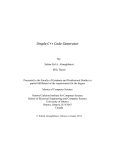
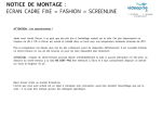
DCN Next Generation
Synoptic Microphone Control
en Software User Manual
LBB 4171/00
About this manual
This user manual is divided into five chapters.
Chapters 1 and 2 provide background information;
chapter 3 and 4 provides detailed user information as
follows:
•
•
•
•
Manual conventions
For clarity this user manual uses consistent styles,
symbols and typographical conventions. They are:
i
Chapter 1 - Synoptic Microphone Control containing a brief overview of the Digital
Congress Network Next Generation, a summary
of the application modules available and an
overview of the functionality of the Synoptic
Microphone application.
Chapter 2 - Getting Started - containing details
on how to start the Synoptic Microphone
Control application from the Startup screen and
a description of the Help facility.
Chapter 3 - Preparing for a Conference containing details about the layout mode,
instructions about making a synoptic layout for
the first time and editing existing synoptic layouts,
and exiting layout mode.
Chapter 4 - Controlling a Conference containing details about the control mode,
instructions about assigning operational modes
and accessing conference information,
controlling a conference and exiting control
mode.
Note
General notes are contained within rules and
indicated with this symbol at the left margin.
Notes are used to draw attention to special
actions or information.
i
Caution
A caution is contained within rules and
indicated with this symbol at the left margin.
Cautions are used to draw attention to actions
or commands that could lead to a loss of
information or damage to equipment
i
Tip
A tip is contained within a box and indicated
with this symbol at the left margin. Tips are
used to provide supplementary information that
may make an action quicker or easier to carry
out.
•
An action (to be carried out by the user) is shown
with a larger round bullet mark.
Typographical conventions
The following typographical conventions (text styles)
are used in this manual:
•
Typed input - information to be typed in using
the keyboard is shown as:
Filename
•
Single key - input via a single key (or keys) on
the keyboard is shown as:
<enter>, <shift>, etc.
•
Multiple keys - input via a combination of keys
pressed together is shown as:
<ctrl>+<p>, <alt>+<f4>
•
Screen text - information that appears on screen
is shown as:
‘Choose Startup Modules:’
Hyperlinks
This manual is also available as a digital document in
the Adobe Portable Document Format (PDF). All
references to pages, figures, tables, etc. in this digital
document contain hyperlinks to the referenced location.
DCN Next Generation Synoptic Microphone Control
en | 3
Table of contents
1
Synoptic Microphone Control ............................. 4
1.1
About Synoptic Microphone Control................. 4
1.1.1 What is Synoptic Microphone Control? ........... 4
Layout mode ............................................................ 4
Control mode........................................................... 4
1.2
What is a synoptic layout?................................... 4
1.2.1 Making a graphical representation ..................... 4
1.3
Controlling microphones ...................................... 4
1.3.1 Conference procedures........................................ 4
1.3.2 Microphone operation modes ............................. 4
Microphone control by operator with request
list ............................................................................... 5
Microphone control by operator with request
and response list .................................................... 5
Microphone control by delegate with request
list ............................................................................... 5
Microphone control by delegate with override 5
Microphone control by delegate with voice
activation................................................................... 5
2
Getting started............................................................ 6
2.1
Starting Synoptic Microphone Control ............. 6
2.1.1 The Startup screen ................................................ 6
Selecting an installation- (and a names) file..... 6
The Synoptic Microphone Control icon ............ 6
2.2
Using Help ............................................................... 6
2.2.1 The Help menu........................................................ 6
2.2.2 Index .......................................................................... 6
2.2.3 Keyboard .................................................................. 7
2.2.4 Commands............................................................... 7
2.2.5 Procedures............................................................... 7
2.2.6 Glossary.................................................................... 7
2.2.7 Using Help ............................................................... 7
2.2.8 About ......................................................................... 7
3
Preparing for a conference .................................. 8
3.1
Using layout mode.................................................. 8
3.1.1 The main window.................................................... 8
3.1.2 The menu bar........................................................... 8
3.1.3 The tool box ............................................................. 8
3.2
Making a layout ....................................................... 9
3.2.1 Layout Options........................................................ 9
3.2.2 Microphone seat numbers.................................... 9
Displaying seat numbers....................................... 9
Automatic seat numbering ................................... 9
Small or large icons ............................................... 9
Displaying a red background for active
microphones ............................................................ 9
Displaying a layout grid ......................................... 9
Snapping to the grid............................................10
Rotating icons .......................................................10
3.2.3 Positioning icons on a layout .............................10
3.2.4 Editing icons in a layout ......................................10
Deleting icons........................................................10
Cutting and pasting icons ..................................11
Copying and pasting icons ................................11
3.3
3.3.1
3.3.2
3.4
3.4.1
3.5
4
4.1
4.1.1
4.1.2
4.1.3
4.2
4.3
4.3.1
4.4
4.4.1
4.5
4.6
4.7
4.7.1
4.7.2
Bosch Security Systems B.V. | 2005 January | 9922 141 70351
Editing seat numbers .......................................... 11
Altering the default screen line length............. 11
Specifying conference procedures.................. 12
Specifying the microphone operation mode.. 12
Microphone Control By ...................................... 12
Microphone Setting ............................................. 12
Active Mics ............................................................ 12
Specifying additional microphone parameters12
Microphone Activity ............................................. 12
Attention Tone....................................................... 14
Ambient Microphone ........................................... 14
Microphones Off After Shift .............................. 14
Working with layout files .................................... 14
Layout file options ................................................ 14
Creating a new layout file................................... 14
Opening an existing layout file .......................... 15
Saving a layout file ............................................... 16
Saving a layout file under a new name............ 16
Deleting a layout file ............................................ 16
Importing a bitmap ............................................... 16
Going to control mode........................................ 17
Controlling a conference .................................... 18
What is control mode? ....................................... 18
Monitoring and controlling a conference........ 18
Conventions used in this chapter..................... 18
Icon status ............................................................. 18
Control mode display options ........................... 18
Small or large icons ............................................. 18
Displaying seat numbers .................................... 19
Rotate...................................................................... 19
Displaying a red background for active
microphones.......................................................... 19
Using control mode ............................................. 19
Switching microphones on and off .................. 19
Switching microphones on ................................ 19
Switching microphones off ................................ 19
Clearing all requests-to-speak .......................... 20
Action box .............................................................. 20
Accessing conference information .................. 20
Checking the conference status ...................... 20
Returning to layout mode ................................... 20
Printing.................................................................... 21
Microphone testing.............................................. 21
Exiting synoptic microphone control................ 22
Temporarily exiting Synoptic Microphone
Control.................................................................... 22
Permanently exiting Synoptic Microphone
Control.................................................................... 22
DCN Next Generation Synoptic Microphone Control
1
Synoptic Microphone
Control
en | 4
returning to layout mode.
i
Before creating a layout, it is useful to know the
seat numbers assigned to all microphones
connected to the system. This helps assigning
seat numbers to icons in your layout, as
Synoptic Microphone Control does not give a
list of all available seat numbers. Seat numbers
are assigned using the System Installation
software (LBB 4185) and are stored in an
installation file.
1.1 About Synoptic Microphone Control
1.1.1 What is Synoptic Microphone Control?
The Synoptic Microphone Control software program
is one of a family of modules designed for controlling
and monitoring conferences and discussions using the
contribution equipment. It is used for configuring and
controlling microphones connected to the system,
and uses icons to produce a graphical representation
of a conference-seating plan. The result is a highly
visual ‘push-button’ conference control program.
Synoptic Microphone Control has two modes:
•
Layout mode
•
Control mode
Layout mode
Is used to create a synoptic view, which contains an
arrangement of icons corresponding to the positions
of actual microphones in the conference venue. Each
type of contribution equipment (delegate unit,
chairman unit, etc.) has its own icon. Synoptic layouts
can be created and modified in layout mode.
Refer to chapter 3.
Control mode
Is used to monitor and control a conference. In
control mode, the color of a particular icon depends
on the state (request-to-speak, active, etc.) of the
actual microphone it represents. Synoptic layouts
generated in layout mode are used in control mode.
Refer to chapter 4.
1.2 What is a synoptic layout?
1.2.1 Making a graphical representation
A synoptic layout is a graphical representation of the
actual location of the microphones, delegate units
and chairman units in a room or hall.
What you create on screen is a plan view of how
your conference venue looks. The layout mode of
Synoptic Microphone Control contains tools for
creating and editing such layouts. Icons (graphical
representations) of the contribution equipment are
used to build up the layout.
In control mode, the icons you have positioned in the
layout become functional, and a conference can be
monitored and/or controlled. The icons are used as
status indicators or buttons to initiate actions for the
unit the icon represents. Icons cannot be moved in
control mode, but a layout can always be edited by
Tip
1.3 Controlling microphones
1.3.1 Conference procedures
To successfully set-up, conduct and organize a
conference it is necessary to provide microphone
management procedures, which facilitate many
different types of conference or discussion.
The system operator (or conference chairman)
requires a choice of operating modes for controlling
delegates waiting to speak, and the number of
delegates who can speak at the same time. In
addition, an automatic mode of operation, that does
not need operator (or chairman) involvement, is
essential.
1.3.2 Microphone operation modes
Allowing conference delegates to activate their
microphones whenever they desire would almost
certainly lead to confusion. However, in some
smaller discussion groups, it is acceptable to allow a
certain amount of freedom. Microphone operation
modes must allow for all circumstances.
i
Note
In this manual, reference is made to the request
list, response list and speakers list. However, it
is not possible to view these lists on-screen
using Synoptic Microphone Control. For more
details, refer to the Microphone Management
user manual.
To manage and control the way delegates and/or the
system operator activate microphones, five
microphone operation modes are possible:
•
Microphone control by operator with request list
•
Microphone control by operator with request
and response list
•
Microphone control by delegate with request list
•
Microphone control by delegate with override
Bosch Security Systems B.V. | 2005 January | 9922 141 70351
DCN Next Generation Synoptic Microphone Control
•
Microphone control by delegate with voice
activation
i
Note
All modes are selected using the ‘System Mic.
Mode...’ command in the ‘Settings’ menu. For
more information refer to paragraph 3.3.1.
Microphone control by operator with request list
Useful in formal, highly structured meetings in which
participants join a ‘request-to-speak’ list by activating
a key on their delegate unit. They can only be
promoted to active status (speaker) via the operator.
The operator can see which delegate is first in the
request-to-speak list. An operator ‘shift’ function gives
this delegate active status and switches off the
microphone of the delegate who has been speaking
longest. The maximum number of simultaneous
active microphones (speakers) can be pre-set by the
operator.
When a participant presses the microphone on/off
key on the delegate unit, it is indicated as a ‘requestto-speak’. No further action is required, and when the
delegate receives active status, the microphone is
automatically switched on (indicated by an
illuminated red LED).
i
Note
When a delegate is listed in the request list the
green LED at the unit is lit, simultaneously the
green microphone LED is lit. When the
delegate is the first in the request list both
LEDs will flash to indicate that the microphone
will be switched on soon.
Microphone control by operator with request and
response list
Also intended for formal, highly structured meetings,
and is similar to microphone control by operator
with request list. However, as well as joining a
‘request-to-speak’ list, it is now possible for a
delegates to make a response request using the
middle votting button on his/her delegate conference
unit.
This is useful in situations where a delegate wants to
give a prompt answer to a matter raised by the
speaker. This request will be given temporary
priority, and will appear at the top of the request list.
When such a response request is promoted to active
status, the current speaker is deactivated, but remains
on the speakers list, and the response delegate is
promoted to the ‘response’ list. The maximum
number of response requests is five, only one of
which can be active at any time.
en | 5
Microphone control by delegate with request list
Useful in less formal meetings where the order of
speaking is determined by the participants and not
the operator. When delegates switch their
microphones on, they are automatically promoted to
the speakers list, providing the speakers list is not full.
No operator action is required to control the
conference, though it is possible. The operator can
also pre-specify the number of speakers.
When the speakers list is full and delegates not on the
speakers list press their microphone button, they are
placed on the request-to-speak list. This list is in
chronological order, and the participant at the top of
the list is automatically promoted to active status
when a currently active speaker switches his/her
microphone off. All other participants move up one
place. When the operator switches off an active
microphone, the delegate at the top of the request-tospeak list is automatically promoted to the speakers
list.
Microphone control by delegate with override
Useful for smaller discussions where participants are
given active status by activating a contribution unit
key. The microphone of the speaker who has been
speaking the longest is automatically switched off. No
operator action is required. There is no request-tospeak list (this mode is sometimes called ‘first-in-firstout’ or FIFO mode). The maximum number of active
microphones (speakers) can be preset by the
operator. When a participant presses the microphone
on/off key on the delegate unit, it is automatically
switched on and the delegate receives active status
(indicated by an illuminated red LED).
Microphone control by delegate with voice
activation
Useful in active discussions in which participants
activate their microphones by speaking (on/off
button is not required). They are automatically given
active status (speaker) while speaking. No operator
action is required.
There is no request-to-speak list, response list or
speakers list. The number of simultaneous active
status microphones (speakers) can be preset by the
operator.
i
Bosch Security Systems B.V. | 2005 January | 9922 141 70351
Note
Operator control and microphone status
monitoring are not possible in ‘Voice
Activation’ mode.
DCN Next Generation Synoptic Microphone Control
2
Getting started
en | 6
installation or names file.
Synoptic Microphone Control requires both an
installation file and a names file for full functionality,
but will work with only an installation file.
2.1 Starting Synoptic Microphone Control
i
2.1.1 The Startup screen
The Synoptic Microphone Control program is started
from the Startup screen (shown below).
Note
A names file is needed to show screenline
icons.
Selecting an installation- (and a names) file
For details on selecting an installation- (and a names)
file, please refer to paragraph 3.2.1 ‘Selecting an
installation- and a names file’ of the Startup user
manual.
The Synoptic Microphone Control icon
For details on the Synoptic Microphone Control icon
and how to start Synoptic Microphone Control from
Startup, please refer to paragraph 3.2.2 Opening other
modules from Startup’ of the Startup user manual.
2.2 Using Help
Figure 1 The Startup screen
i
Note
For starting the Startup program from an icon
in the Windows desktop, refer to the Startup
user manual.
The software uses two user-created files that contain
important information about the installed hardware
configuration and about delegates’ names. These files
are:
•
Installation file - containing information about
channel assignment and the numbers that have
been assigned to all microphones connected to
the . These seat numbers are assigned using the
System Installation software (LBB 4185).
•
Names file - containing information about the
name, seat number and other conference and
personal details of participating delegates. Names
files are created using the Delegate Database
software (LBB 4180).
The software modules may be started up from the
Startup main window without specifying either an
installation or names file. However, some software
modules will not run without the appropriate
2.2.1 The Help menu
The ‘Help’ menu in the title bar contains commands
for an on-screen help facility. This help facility
contains information on all commands in the ‘File’
menu, on which keyboard keys are functional, a
description of how to use the software, information
on how to use the help facility itself, plus an index
and a glossary of terms. All information contained in
this user manual is also found in the ‘Help’ facility.
The ‘Help’ facility contains the following options:
•
Index
•
Keyboard
•
Commands
•
Procedures
•
Glossary
•
Using Help
•
About Synoptic Microphone Control.
2.2.2 Index
To access the index:
•
Select the ‘Help’ menu and click on ‘Index’.
A full list of subjects covered by the help facility is
given in alphabetical order. For more information on
any subject contained in the index:
•
Bosch Security Systems B.V. | 2005 January | 9922 141 70351
Click on the required subject in the index.
DCN Next Generation Synoptic Microphone Control
An on-screen page with the requested information
will appear.
2.2.3 Keyboard
This gives information on which keys on your
keyboard can be used with the software. This
includes using keys to activate menu items, to move
around in dialogue boxes, for short cuts, and to select
options from the main window. To access the
‘Keyboard’ help facility:
•
Select the ‘Help’ menu and click on ‘Keyboard’.
A list of different key types is given. For more
information on any key type contained in the list:
•
Click on the required key type in the list.
An on-screen page with the requested information
will appear.
2.2.4 Commands
This gives information on all menu options, covering
the ‘File’, ‘Edit’, ‘View’, ‘Settings’ and ‘Help’ menus.
To access the ‘Commands’ help facility:
•
Click on the required menu group in the list.
A list of options in the selected menu group is given.
For more information on any option contained in the
list:
•
•
Select the ‘Help’ menu and click on ‘Glossary’.
A list of terms used in the help facility is given in
alphabetical order. For more information on any
term contained in the glossary:
•
Click on the required subject in the index.
A window with the requested information will appear.
2.2.7 Using Help
This gives information on how to use the help facility.
To access the ‘Using Help’ facility:
•
Select the ‘Help’ menu and click on ‘Using Help’.
A list of topics is given. For more information on any
topic contained in the list:
•
Click on the required topic in the list.
A list of options for the selected topic is given. For
more information on any option contained in the list:
•
Click on the required option in the list.
An on-screen page with the requested information
will appear.
Select the ‘Help’ menu and click on ‘Commands’.
A list of menu groups is given. For more information
on any menu group contained in the list:
•
en | 7
2.2.8 About
This provides software release information. To
display the ‘About...’ window:
•
Select the ‘Help’ menu and click on ‘About Syn.
Mic. Control...’.
The following window appears:
Click on the required option in the list.
An on-screen page with the requested information
will appear.
2.2.5 Procedures
This gives information on how to use the software.
To access the ‘Procedures’ help facility:
•
Select the ‘Help’ menu and click on ‘Procedures’.
A list of topics is given. For more information on any
topic contained in the list:
•
Click on the required topic in the list.
A list of options for the selected topic is given. For
more information on any option contained in the list:
•
Click on the required option in the list.
An on-screen page with the requested information
will appear.
Figure 2 The ‘About...’ window
2.2.6 Glossary
To access the glossary:
To remove this window:
•
Bosch Security Systems B.V. | 2005 January | 9922 141 70351
Click on the ‘OK’ push button.
DCN Next Generation Synoptic Microphone Control
3
Preparing for a conference
3.1 Using layout mode
3.1.1 The main window
The Synoptic Microphone Control main window
contains a layout area and a toolbox. From this you
will create or edit your synoptic layout.
en | 8
options is as follows:
File
Edit
View
Settings
New…
Undo
Numbers
System Mic.
Mode…
Open…
Cut
Small Icons
Save
Copy
Grid
Save As…
Paste
Rotate
Image
Delete…
Delete
Shift!
Clear
Requests!
Help
Index…
Keyboard
Mic Activity…
Microphone
Test…
Select Grid…
Comman
ds
Procedure
s
Action Box
Print
Activity…
Number
Exit
Snap
Glossary
Auto Numbers
Using
Help
Setting
Layout
Red
background
for active
microphones
Attention Tone
Ambient Mic.
Control
About
Syn. Mic.
Control…
Mic’s off after
shift
3.1.3 The tool box
The toolbox is situated on left side of the window as
default. You can, however, move this anywhere in
the window. To do so:
•
Position the mouse pointer at the top of the
toolbox - though not on any icons - and drag it to
the desired location.
The toolbox contains icons representing all available
microphone possibilities. These are:
Figure 3 The Synoptic Microphone main window
In the title bar, the software displays the layout file
name. The name displayed is that of the last-used
layout file corresponding to that installation file. A
new layout file is automatically given the same name
as the installation file if no layout file already exists.
If an installation file has been opened for which no
layout file already exists (for example, the very first
time the program is used), the layout area is empty.
i
Note
The synoptic layout area is actually larger than
the window. When a layout is opened, the
viewed area is always the top left corner. To
enable you to work on unseen parts of the
layout, scroll bars are provided to move the
viewed area.
If the layout window is not full screen size, you may
enlarge it to fill the desktop. To do so:
•
Click on the maximize button in the top right
corner of the window’s title bar.
Delegate unit
Used for tabletop or built-in units with microphone,
loudspeaker, on/off button and status indicators.
Chairman unit
Used for tabletop or built-in units with microphone,
priority key, on/off button and status indicators. Up
to three chairman units may be included in a layout.
Podium microphone
Used for e.g. gooseneck type microphones mounted
on a desk or podium.
Microphone on floorstand
Used for e.g. microphones mounted on a floorstand.
Lavalier microphone
A mobile microphone carried by the user on a neck
strap or tie clip.
Screenline
Gives the screenline of the delegate as specified in
the Delegate Database application.
3.1.2 The menu bar
All menu options referred to in this user manual are
contained within the menu bar, located underneath
the title bar at the top of the main window. Access to
drop-down menus is gained by clicking on the menu
title, displayed in the menu bar. The list of menu
Bosch Security Systems B.V. | 2005 January | 9922 141 70351
DCN Next Generation Synoptic Microphone Control
There are two other elements in the toolbox:
en | 9
that this option is enabled.
i
Microphone total
The total number of microphones with a valid seat
number that remain to be positioned in the synoptic
layout is displayed.
Go to Control Mode
There is also an icon with ‘Control’ written
underneath. Clicking on this exits layout mode and
enters control mode (normally used when the layout
is ready - refer to chapter 3).
3.2 Making a layout
Note
The seat numbers assigned using ‘Auto
Numbering’ are the seat numbers in the
current installation file. If all installation file seat
numbers have been used, any further icons will
not be given seat numbers.
Small or large icons
If you are planning a layout with a large number of
microphones (more than 50, for example), the ‘Small
Icons’ option reduces the size of the screen icons and
the toolbox icons. To do so:
•
Select the ‘View’ menu and click on ‘Small Icons’.
To restore the icons to normal size:
3.2.1 Layout Options
When creating a layout, there are a number of
options in the ‘View’ and ‘Settings’ menus that make
this task easier. These are:
•
Displaying icon numbers
•
Automatic numbering of icons
•
Changing the icon size
•
Displaying a layout grid in various sizes
•
‘Snapping’ icons to the grid
•
Rotating icons
•
Displaying a red background for active
microphones
•
The icons automatically return to their normal size.
Figure 4 Large icons
i
3.2.2 Microphone seat numbers
Synoptic Microphone Control uses seat numbers as
specified in the installation file to identify
microphone icons in a layout.
Displaying seat numbers
The seat number is displayed beneath a microphone
icon as default. If you wish to disable this option:
•
Select the ‘View’ menu and click on ‘Numbers’.
The tick mark (√) will subsequently disappear to
indicate that this option is disabled.
i
Select the ‘View’ menu and click on ‘Large Icons’.
Figure 5 Small icons
Note
Small icons can only be displayed without seat
numbers.
Displaying a red background for active
microphones
When this option is enabled, active microphone
icons will have a red background. To do so:
•
Select the ‘View’ menu and click on ‘Red
background for active mics’.
A tick mark (√) will appear to indicate that this
option is enabled.
Note
Seat numbers are always assigned to
microphone icons in your synoptic layout if the
‘Auto Numbers’ option is active
Displaying a layout grid
This option fills the screen with squares to help
position the icons. To do so:
•
Select the ‘View’ menu and click on ‘Grid’.
Automatic seat numbering
This option assigns sequential seat numbers to
microphone icons, starting with the lowest available
seat number. To enable this option:
The default grid size is 32 x 32 screen pixels. To
select one of the two smaller grid sizes available (16 x
16 or 8 x 8 pixels):
•
•
Select the ‘Settings’ menu and click on ‘Auto
Numbers’.
A tick mark (√) will subsequently appear to indicate
Bosch Security Systems B.V. | 2005 January | 9922 141 70351
Select the ‘Settings’ menu and click on ‘Select
Grid’.
DCN Next Generation Synoptic Microphone Control
en | 10
The following dialogue box appears:
i
Caution
You should take care so as not to position
icons on top of each other in a synoptic layout,
especially when the ‘Snap’ function is enabled.
In such cases, only the top icons will be
displayed, so the icons underneath cannot be
controlled.
To move an icon at any time in layout mode:
•
Figure 6 The 'Select Grid' dialog box
•
Click on the radio button for the desired grid
size.
•
Click on the ‘Ok’ push button.
i
Note
Select the icon to be moved and drag it to the
new location.
The icon turns blue to indicate that it is selected.
3.2.4 Editing icons in a layout
The Synoptic Microphone Control main window
includes an ‘Edit’ menu with commands for undoing
commands and cutting, copying, pasting and deleting
icons. This menu also allows you to edit an icon’s
seat number. Individual or groups of icons can be
cut, deleted, copied and pasted. To select more than
one icon:
Clicking on the ‘Cancel’ push button closes
the dialogue box without carrying out the
option. This applies to all dialogue boxes in
Synoptic Microphone Control.
•
Click on the first icon required.
•
Press and hold the <CTRL> key.
Snapping to the grid
Enabling this option causes icons to automatically
align to the grid. To do so:
•
Click on further icons while holding the <CTRL>
key.
•
Select the ‘Settings’ menu and click on ‘Snap’.
Once snapping has been enabled, all existing icons in
the layout will be aligned to the grid. Any new icons
will automatically be aligned as they are positioned.
Rotating icons
Causes the layout to automatically rotate clockwise in
steps of 90°. To rotate the synoptic layout.
•
Select the ‘View’ menu and click on ‘Rotate
Image’.
When you have selected all icons you require:
•
Release the <CTRL> key.
Icons that have been selected will be colored.
To de-select one or more icon in a group of selected
icons:
•
Press and hold the <CTRL> key.
•
Click on the icon to be de-selected.
•
Release the <CTRL> key.
De-selected icons turn from colored to gray.
3.2.3 Positioning icons on a layout
To create a layout, the first step is to position the
icons according to the actual layout. To do so:
•
Click on the appropriate icon type in the toolbox
and drag it to the desired location.
When an icon is selected, it changes from gray to
blue. The mouse pointer also changes from an arrow
to a hand. An icon remains colored (indicating it is
the last selected icon) until another one is selected, or
until the mouse is clicked on an area where there are
no icons.
Deleting icons
To delete icons from a synoptic layout:
•
Select the icon(s) to be deleted.
•
Select the ‘Edit’ menu and click on ‘Delete’.
i
Bosch Security Systems B.V. | 2005 January | 9922 141 70351
Tip
If you make a mistake when editing a layout, the
‘Edit’ menu has an ‘Undo’ command. Clicking
on this command will undo the last edit action,
except in the case of seat numbers. An altered
seat number cannot be ‘undone’.
DCN Next Generation Synoptic Microphone Control
en | 11
Cutting and pasting icons
If you want to move one or more icons from one
place to another on the layout, this can be done with
the ‘Cut’ and ‘Paste’ commands. To do this:
•
Click on the icon whose seat number requires
editing.
•
Select the ‘Edit’ menu and click on ‘Number’.
•
Select the icon(s) to be moved.
•
The seat number beneath the microphone icon
becomes an edit field.
Select the ‘Edit’ menu and click on ‘Cut’.
•
Type in the new icon number.
•
Press the <ENTER> key.
The selected icon(s) are moved from the layout to a
‘clipboard’ buffer memory (which is not visible). To
retrieve them:
•
Select the ‘Edit’ menu and click on ‘Paste’.
An outline representation of the cut icon(s) appears
in the window. The mouse pointer turns into a crosshair cursor in the center of this area.
•
Position the cut icons by moving the mouse.
•
Click on the mouse button to paste the icons.
The mouse pointer returns to an arrow and the icons
become visible.
Copying and pasting icons
If you want to copy one or more icons (leaving the
originals on the layout), and then place the copies
elsewhere, this can be done with the ‘Copy’ and
‘Paste’ commands. To do so:
•
Select the icon(s) to be copied.
•
Select the ‘Edit’ menu and click on ‘Copy’.
The selected icon(s) are copied from the layout to the
‘clipboard’ buffer memory. To retrieve them:
•
Select the ‘Edit’ menu and click on ‘Paste’.
An outline representation of the copied icon(s)
appears in the window. The mouse pointer turns into
a cross-hair cursor in the center of this area.
•
Position the copied icons by moving the mouse.
•
Click on the mouse button to paste the icons.
The mouse pointer returns to an arrow and the icons
become visible.
i
Tip
Icons that have been copied or cut to the
clipboard can be pasted onto a layout more
than once, and remain on the clipboard until
another cut or copy action is performed.
Editing seat numbers
If an icon or icons have been deleted, copied or
pasted into the layout, the seat numbers must be
edited. To do so:
This performs a check on the seat number that has
been entered. If the seat number is valid, it will
appear under the icon.
i
Note
Seat numbers must correspond to the seat
numbers in the current installation file.
If an invalid seat number is entered, a warning with
the following text is displayed:
‘The seat number entered does not exist’
•
Click on the ‘OK’ push button and repeat the
number editing for that icon.
i
Tip
Double-clicking on a microphone icon
automatically enters the seat number editing
mode.
If you try to create more than 500 icons the following
message appears:
‘This action is not possible because the
maximum number of icons will be exceeded.’
Altering the default screen line length
When a screen line is displayed instead of a
microphone icon, two lines of maximum 15
characters are displayed by default. It is possible to
change the number of characters displayed on each
line to any number between 0 and 15. This would be
useful if, for example, it was necessary to save layout
screen space. To alter the default setting you must
edit the DCNNG.INI file.
To do so:
•
Open the DCNNG.INI file in the C:\windows or
C:\WINNT directory.
•
In the section of the DCNNG.INI file titled
[Synoptic], enter the next line:
ScreenLineLength=#
where # is a number between 0 and 15.
•
Save the DCNNG.INI file then exit it.
Bosch Security Systems B.V. | 2005 January | 9922 141 70351
DCN Next Generation Synoptic Microphone Control
•
Close the application and restart it from Startup
to implement the change.
en | 12
option is disabled.
i
3.3 Specifying conference procedures
3.3.1 Specifying the microphone operation mode
For more general information on microphone
operation modes please refer to paragraph 1.3.2. For
information on the operator possibilities in each
mode, please refer to paragraph 4.3.
•
Select the ‘Settings’ menu and click on ‘System
Mic Mode...’
The following dialogue box appears:
Note
This option is only available for ‘Operator with
Request List’, ‘Operator with Request and
Response List’ and ‘Delegate with Request
List’ modes. For the other two modes, this
option button is not displayed.
In this part of the dialogue box, there is also an
option, which allows delegates to switch their own
microphones off. This option is only available in
‘Operator with Request List’ mode and ‘Operator with
Request and Response List’ mode. The default setting
is enabled, meaning delegates can switch off their
microphones. To disable this function:
•
Click on the ‘Allow Microphone Off’ check box in
‘Microphone Settings’.
The tick mark (√) will disappear to indicate this
option is disabled.
Active Mics
You can specify the number of active delegate
microphones permitted (the length of the speakers
list). The minimum is one and the maximum is four.
To do so:
•
Click on the desired radio button in ‘Active Mics’.
i
When ‘Delegate with Voice Activation’ is
selected, the minimum number of active
microphones is two, not one. The maximum
number is still four.
Figure 7 The ‘System Microphone Mode’ dialogue
box
Microphone Control By
This part of this dialogue box is for selecting the
microphone mode. To do so:
•
Click on the desired ‘Microphone Control By’
radio button.
In addition to allowing selection of the microphone
mode, the ‘System Microphone Mode’ dialogue box
also allows you to specify two other parameters,
‘Microphone Settings’ and ‘Active Mics’.
Microphone Setting
This part of the dialogue box allows you to give
delegates the ability to cancel a request-to-speak. The
default setting is enabled, meaning delegates can
cancel requests to speak. To disable this function:
•
Click on the ‘Allow Cancel Request’ check box
in ‘Microphone Settings’.
Note
3.3.2 Specifying additional microphone
parameters
It is also possible to specify the following:
•
Printing or saving a record of microphone
activity
•
Attention tone
•
Ambient microphone
•
Microphone off after shift
i
Note
Printing or saving microphone activity is part of
conference control and is covered in chapter 4.
Microphone Activity
Enables microphone activity to be monitored and
sent to a file, a printer, an auxiliary output, or a
combination of these options. The default setting is
no monitoring. To define microphone activity:
The tick mark (√) will disappear to indicate this
Bosch Security Systems B.V. | 2005 January | 9922 141 70351
DCN Next Generation Synoptic Microphone Control
•
Select the ‘Settings’ menu and click on ‘Mic.
Activity’.
The following dialogue box appears:
en | 13
up to 80 characters long. This text box may be left
blank. Real-time printing is possible using a serial
printer.
i
Note
By default is comport 2 used on the local PC,
but it can be routed to any comport or even to
a different PC by adding the following section
to the DCNNG.INI file:
[MicActLogging]
PrtPort=X
PrtPortPCID=NR
where:
PrtPort
PrtPortPCID
‘X’ is the comport number (1-4)
‘NR’ is always 1 in a single PC
system. In case of a multi-PC
system, ‘NR’ is the number of
the PC on which the output
Figure 8 The ‘Microphone Activity’ dialogue box
must
This dialogue box contains check boxes for sending
microphone activity to a file, a printer or auxiliary.
Any combination of these options can be selected as
follows:
be produced. Server PC =1,
Client PC is from 2 until 10
The port settings can be changed via the
Windows Device Manager.
•
Click on the check boxes of the desired option(s).
i
i
The data layout is defined as follows:
Note
<time><event><seatnumber><screenline><CR><LF>
The ‘File’ check box is only active after you
have specified a destination in the ‘Send To’
field.
where:
time
event
Time of the event in hh:mm:ss
One of the following texts:
MICROPHONE ON
MICROPHONE OFF
PRIORITY ON
PRIORITY OFF
ALL MICROPHONES OFF
If you select ‘File’:
The ‘Send To’ text box is highlighted. You can enter
a file destination and name, which must be a valid
MS-DOS name no longer than eight characters.
i
Note
seatnumber
The seatnumber of the delegate,
empty if the event is
”ALL MICROPHONES OFF”
screenline
Examples:
Note
The data layout is defined as follows:
13:14:03 MICROPHONE ON 0002 Mr President
13:14:03 ALL MICROPHONES OFF
<time><event><seatnumber><screenline><CR><LF>
where:
time
event
Time of the event in hh:mm:ss
One of the following texts:
MICROPHONE ON
MICROPHONE OFF
PRIORITY ON
PRIORITY OFF
ALL MICROPHONES OFF
seatnumber
The seatnumber of the delegate,
empty if the event is
If you select ‘Auxiliary’:
If the ‘Auxiliary’ check box is selected, information
on microphone activity is made available on the
COM port 2 of the PC. This can be used to direct a
camera to the current speaker, for example. For more
information, please refer to the Installation and User
Instructions.
”ALL MICROPHONES OFF”
screenline
Examples:
The screenline of the delegate
The screenline of the delegate
13:14:03 MICROPHONE ON 0002 Mr President
13:14:03 ALL MICROPHONES OFF
If you select ‘Printer’:
The ‘Page Header’ text box is highlighted. A
descriptive name of the conference may be entered
Bosch Security Systems B.V. | 2005 January | 9922 141 70351
DCN Next Generation Synoptic Microphone Control
i
indicate that this option is disabled. To enable the
attention tone, repeat the above.
Note
By default is comport 2 used on the local PC,
but it can be routed to any comport or even to
a different PC by adding the following section
to the DCNNG.INI file:
[MicActLogging]
Comport=X
ComPortPCID=NR
where:
ComPort
ComPortPCID
‘X’ is the comport number (1-4)
‘NR’ is always 1 in a single PC
system. In case of a multi-PC
system, ‘NR’ is the number of
the PC on which the output
must
be produced. Server PC =1,
Client PC is from 2 until 10
The port settings can be changed in the
Windows Device Manager.
i
en | 14
Note
The data layout is identical to the Error logging
layout in Startup, to make processing easier
when both loggings are routed to the same
comport. The data layout is defined as follows:
<action code><state><seatnumber><CR><LF>
where:
action code
state
seatnumber
$ microphone on/off
& microphone request on/off
# priority on/off
* response request on/off
1 on
2 off
3 all off
The seatnumber of the delegate,
When state equals 3
seatnumber is “0000”
Examples:
$10001<CR><LF>
&30000<CR><LF>
#20B31<CR><LF>
*10034<CR><LF>
Seat 1, microphone on
All request off
Seat B31, priority button off
Seat 34 response request on
Ambient Microphone
This option allows you to enable or disable a
microphone located in the conference venue that
picks up ambient noise. If this microphone is
enabled, it will automatically switch on if all other
microphones in the conference venue are switched
off. If any microphones are then switched on, the
ambient microphone will automatically be switched
off. To turn the microphone on:
•
Select the ‘Settings’ menu and click on ‘Ambient
Microphone’. (the tick mark (√) will subsequently
appear to indicate that this option is enabled).
To turn the microphone off, repeat the above.
Microphones Off After Shift
This option allows you to determine that when a
delegate is promoted from the request list to the
speakers list, only that delegate’s microphone will be
activated. The microphones of all other delegates in
the speakers list are deactivated. To enable this
function:
•
Select the ‘Settings’ menu and click on ‘Mic’s off
after shift’.
The tick mark (√) will subsequently appear to
indicate that this option is enabled. To disable the
option, repeat the above procedure.
3.4 Working with layout files
3.4.1 Layout file options
The ‘File’ menu has commands for:
•
Opening a new layout file
•
Opening an existing layout file
•
Saving a layout file under its current name
•
Saving a layout file under a different name
•
Deleting a layout file
•
Importing a bitmap
•
Printing microphone activity
•
Exiting the Synoptic Microphone Control
program
Once you have selected all options:
•
i
Click on the ‘Ok’ push button.
Note
Exiting the Synoptic Microphone Control
program and printing are both covered in
chapter 4.
Attention Tone
This allows you to enable or disable a tone, which
sounds when the priority key is pressed on a
chairman unit. Default the tone is on. To turn the
attention tone off:
Creating a new layout file
To open a new layout file:
•
•
Select the ‘Settings’ menu and click on ‘Attention
Tone’.
The tick mark (√) will subsequently disappear to
Select the ‘File’ menu and click on ‘New...’.
If there are no conditions that cause an error message
to be displayed, the following dialogue box appears:
Bosch Security Systems B.V. | 2005 January | 9922 141 70351
DCN Next Generation Synoptic Microphone Control
en | 15
•
Click on the ‘Ok’ push button.
The ‘New’ dialogue box appears. To change the
duplicate seat numbers:
•
Click on the ‘Cancel’ push button.
You will return to the current layout file, and can
then edit the duplicate seat numbers.
Figure 9 The ‘New’ dialogue box
The dialogue box contains a text box for entering the
file name. A text insertion point is already in the text
box and you can type a name up to 12 characters
long.
•
Type the desired layout file name in the text box.
•
Click on the ‘Ok’ push button.
A new layout file (with no microphone icons placed)
opens and the name appears in the title bar at the top
of the window.
If you have requested to open a new layout file
before saving changes to the current layout, a
warning message with the following text is displayed:
‘Changes have been made to <filename>.’
‘Do you want to save?’
•
Click on the ‘Yes’ push button to save the
changed layout file and open the new layout file.
•
Click on the ‘No’ push button to open the new
layout file without saving the changed layout file.
•
Click on the ‘Cancel’ push button to return to the
‘New’ dialogue box.
i
Note
If you proceed to open a new layout file after
the ‘duplicate seat numbers’ message
appears, the ‘Changes have been made to
<filename>’ message also appears. If you then
save the changes, the duplicate seat numbers
are also saved. When you re-open that layout
file, the ‘duplicate seat numbers’ error
message will re-appear.
Opening an existing layout file
To do so:
•
Select the ‘File’ menu and click on ‘Open...’.
If there are no conditions that cause an error message
to be displayed, the following dialogue box appears:
If you have typed a filename that already exists, a
warning message with the following text is displayed:
‘A file already exists with this name’
•
Click on the ‘OK’ push button. You can then
enter a unique name in the ‘New’ dialogue box.
If there are icons without seat numbers in the current
file, a warning message with the following text is
displayed before the ‘New’ dialogue box appears:
‘Icon(s) without seat numbers will be deleted.
Do you want to continue?’
•
Click on the ‘Ok’ push button to open the ‘New’
dialogue box.
•
Click on the ‘Cancel’ push button to return to the
current layout file and edit the icons without seat
numbers.
If there are two or more icons with the same seat
number, a warning message is displayed before the
‘New’ dialogue box appears:
‘Two or more icons have the same seat number!’
Figure 10 The ‘Open’ dialogue box
This dialogue box contains a list box for selecting the
layout file name. The name of the current layout file
is also displayed. When the ‘Open’ dialogue box
opens, the list box contains all available layout files.
If the list contains more names than can be
displayed, a scroll bar is provided. To open a layout
file:
•
Click on the name in the list.
•
Click on the ‘Ok’ push button.
If changes have been made to the current layout file,
or there are duplicate seat numbers or icons without
seat numbers, the same error messages will appear as
for ‘Creating a new layout file’. The same procedure
should be followed. For more details, please refer to
Bosch Security Systems B.V. | 2005 January | 9922 141 70351
DCN Next Generation Synoptic Microphone Control
paragraph 3.4.1.
i
Note
When an existing file is opened, control mode
is automatically started. To return to layout
mode, select the ‘Edit’ menu and click on
‘Layout’.
en | 16
error messages will appear as for ‘Creating a new
layout file’. The same procedure should be followed.
Deleting a layout file
If you wish to delete a layout file:
•
Select the ‘File’ menu and click on ‘Delete...’
The following dialogue box appears:
Saving a layout file
To save the current layout file:
•
Select the ‘File’ menu and click on ‘Save’.
If there are duplicate seat numbers or icons without
seat numbers, the same error messages will appear as
for ‘Creating a new layout file’. The same procedure
should be followed. For more details, please refer to
paragraph 3.4.1.
i
Note
It is useful to periodically save a layout while
creating it in case of a system breakdown or
other failure that could result in the accidental
loss of the layout file.
Saving a layout file under a new name
This allows you to save the current layout file under
a different name. By doing so, the original file
remains unaltered. To do so:
•
Select the ‘File’ menu and click on ‘Save As...’.
The following dialogue box appears:
Figure 12 The ‘Delete’ dialogue box
This dialogue box contains a list box for selecting the
file to be deleted. If the list contains more names
than can be displayed, a scroll bar is provided.
•
Click on the name in the list.
•
Click on the ‘Delete’ push button.
Another dialogue box will appear, with the text:
‘Are you sure you want to delete file
<filename>’
If you still want to continue:
•
Click on the ‘OK’ push button.
The file is deleted.
i
Note
You cannot delete the currently active file.
Figure 11 The ‘Save As’ dialogue box
This dialogue box contains a text box for entering
the new layout file name. When the ‘Save As...’
dialogue box opens, a text insertion point is already
in the text box and you can type a name up to 12
characters long.
•
Type the desired layout file name in the text box.
•
Click on the ‘Ok’ push button.
The layout file is saved with the new name, which
appears in the title bar at the top of the window. The
original file is unchanged. If there are duplicate seat
numbers or icons without seat numbers, the same
Importing a bitmap
You can import a bitmap to use as a background for
the synoptic layout.
i
Note
You can only import files which have a .bmp
extension, and which have no more than 256
colors.
To do so:
•
Select the ‘File’ menu and click on ‘Import...’
The following dialogue box appears:
Bosch Security Systems B.V. | 2005 January | 9922 141 70351
DCN Next Generation Synoptic Microphone Control
Figure 13 The ‘Import’ dialogue box
This is a standard windows dialogue box. The default
directory is displayed in the ‘Folders:’ list box on the
right hand side of the window. To change to a
different directory:
•
Double click on the required directory.
To select a file for importing:
•
Type the file name into the ‘File Name:’ text box.
•
Click on the ‘OK’ push button.
The selected file will be imported.
i
Tip
You can also select a file to import by double
clicking on the filename in the list box
underneath the ‘File Name:’ text box.
3.5 Going to control mode
It is possible for you to leave layout mode and go
into control mode at any time. To do so:
•
Click on the ‘Control’ button in the toolbox.
If there are any invalid seat numbers, or icons
without seat numbers, the appropriate error message
will be displayed. It is not possible to enter control
mode until valid seat numbers are entered. Any
invalid seat numbers entered are not accepted by the
software.
i
Note
If the system does enter control mode, any grid
displayed in layout mode will disappear.
To return to layout mode from control mode:
•
Select the ‘Edit’ Menu and click on ‘Layout’.
Bosch Security Systems B.V. | 2005 January | 9922 141 70351
en | 17
DCN Next Generation Synoptic Microphone Control
4
en | 18
Controlling a conference
i
If the ‘Red background for active mics’ option
in the ‘View’ menu is enabled, the active
microphone icons will have a red background.
If this option is not enabled, active microphone
icons are only partially red.
4.1 What is control mode?
4.1.1 Monitoring and controlling a conference
In control mode, the layout created in layout mode is
used as a basis for monitoring and controlling a
conference. The icons in the layout are functional,
rather than just representational as in layout mode.
They indicate the status of each microphone and
function as buttons for the microphone the icon
represents. In this mode you can control almost all
microphone activities, and have an overview of the
status of microphones in a conference. The layout
cannot be altered in control mode.
4.1.2 Conventions used in this chapter
•
Microphone - covers delegate and chairman
units, lavalier-, floorstand and podium
microphones.
•
Speakers list - a microphone on the speakers list
is on and therefore active (except when switched
off in ‘Operator with Request List’ or ‘Operator
with Request and Response List’.
•
Request-to-speak list - contains delegates that
are waiting to speak. Delegates gain access to this
list by pressing their microphone button or by
making a response request when the speakers list
is full, or via the operator in Microphone
Management (LBB 4170).
•
Response list - can contain a maximum of one
response microphone, which has been promoted
from the request-to-speak list.
•
Inactive - an inactive microphone is one that has
been turned off by the operator or by the
delegate him/herself.
•
Oldest speaker - the microphone longest on the
speakers list.
4.1.3 Icon status
In control mode the color of the microphone icons
indicates their status. The possibilities are:
•
Grey - microphone off (inactive)
i
•
•
Flashing red - last minute of speaking time
i
Red - microphone on (active), therefore on the
speakers list
Note
This is only applicable if a limit has been set on
speaking time using Microphone Management
(LBB 4170).
•
Green - microphone in request-to-speak list
Flashing yellow - response microphone in
request-to-speak list
Flashing green - microphone is first in the
request-to-speak list
Red diagonal line - microphones that are
disconnected are shown by an icon crossed with
a red diagonal line.
•
•
•
i
Note
If a microphone represented by a screenline
icon is disconnected, there is no red diagonal
line. In this case the icon turns gray, and should
not be confused with voice-activated
microphones, which are always displayed by
gray icons.
4.2 Control mode display options
There are a number of options in the ‘View’ and
‘Settings’ menus that make controlling a conference
easier:
•
Small or large icons
•
Displaying seat numbers
•
Rotating an image
•
Displaying a red background for active
microphones
i
Note
These options are also available in layout
mode, and are described in paragraph 3.2.
Note
Voice activated microphones are always
displayed by gray icons.
Note
Small or large icons
If you are working on a layout with a large number
of icons (more than 50, for example), you can
activate the ‘Small Icons’ option. This reduces the size
of the screen icons.
•
Bosch Security Systems B.V. | 2005 January | 9922 141 70351
Select the ‘View’ menu and click on ‘Small Icons’.
DCN Next Generation Synoptic Microphone Control
To restore the icons to normal size:
•
Select the ‘View’ menu and click on ‘Large Icons’.
Displaying seat numbers
This option displays the seat numbers assigned to a
microphone beneath that microphone’s icon. The
default setting is on. If you wish to disable this
option:
•
en | 19
Switching microphones on
To switch any inactive microphone on:
•
Click on the icon of the inactive microphone you
wish to switch on.
•
In ‘Operator with Request List’ mode, ‘Operator
with Request and Response List’, ‘Delegate with
Request List’ mode and ‘Delegate with Override’
mode, clicking on an inactive microphone icon
automatically makes that microphone active.
This applies to all inactive microphones, whether
they are on the request-to-speak list or not (only
applicable to ‘Operator with Request List’ mode
and ‘Delegate with Request List’ mode). If the
speakers list is full, then the first microphone is
automatically switched off and removed from the
speakers list to make room.
Select the ‘View’ menu and click on ‘Numbers’.
Rotate
The layout may have been created looking from a
different position than the one you occupy as
operator. To compensate for this, the rotate function
allows the layout to be rotated clockwise in 90° steps
around the center of the window. The icons and seat
numbers are always shown upright. To rotate the
synoptic layout:
•
Select the ‘View’ menu and click on ‘Rotate
Image’.
The layout will automatically rotate through 90°
about the central point of the part of the layout that is
visible in the window. To rotate the image through
180°, use ‘Rotate’ twice, and for 270°, use ‘Rotate’
three times.
To switch on the first microphone on the request-tospeak list in ‘Operator with Request List’, ‘Delegate
with Request List’ and ‘Operator with Request and
Response List’ modes:
•
i
Displaying a red background for active
microphones
When this option is enabled, active microphone
icons will have a red background. To do so:
•
Click on the ‘Shift!’ option on the menu bar, or
click on the ‘Shift’ push button in the action box.
You can also simply click on the microphone
icon.
The ‘Shift!’ and ‘Clear Requests!’ options on
the menu bar can be displayed as an action
box with push buttons for these two functions.
For more details, please refer to page 20.
Select the ‘View’ menu and click on ‘Red
background for active mics’.
i
4.3 Using control mode
i
4.3.1 Switching microphones on and off
In control mode, depending on the microphoneoperating mode, the operator can switch inactive
microphones on, and switch them off again. It is also
possible to clear all requests-to-speak.
i
Note
A response request to speak is always
automatically at the top of the request-to-speak
list, and is therefore the first to be automatically
activated.
Tip
Before using control mode, you should be
familiar with the characteristics of each of the
five microphone operating modes. Please refer
to paragraph 1.3.2 and paragraph 3.3.1 for
further information.
Note
Switching microphones off
To switch an active microphone off:
•
Click on the active microphone icon.
•
In ‘Operator with Request List’ mode and
‘Operator with Request and Response List’,
clicking on an active microphone icon turns the
microphone off but does not remove it from the
speakers list. Clicking on the icon again turns the
microphone back on.
In ‘Delegate with Request List’ mode, turning an
active microphone off causes a shift action to
occur. If there is a request-to-speak list, then the
first microphone in the request-to-speak list is
automatically promoted to fill this space. All
•
Note
In ‘Delegate with Voice Activation’ mode, no
operator intervention is possible.
Bosch Security Systems B.V. | 2005 January | 9922 141 70351
DCN Next Generation Synoptic Microphone Control
other microphones on the request-to-speak list
are shifted up one place.
In ‘Delegate with Override’ mode, clicking on an
active microphone turns the microphone off and
removes it from the speakers list. There is no
automatic replacement facility.
•
i
Clearing all requests-to-speak
This can only be carried out in either ‘Delegate with
Request List’, ‘Operator with Request and Response
List’ or ‘Operator with Request List’ mode. If you wish
to clear all requests-to-speak:
Click on the ‘Clear Requests!’ option on the menu
bar, or click on the ‘Clear Requests’ push button
in the action box.
Action box
The ‘Shift!’ and ‘Clear Requests!’ options on the menu
bar can be displayed as an action box with push
buttons for these two functions. To display the action
box
•
4.4 Accessing conference information
4.4.1 Checking the conference status
The status of the Synoptic Microphone Control can
be checked at any time during a conference. To
check the status:
•
Note
The delegate at the top of the request-to-speak
list will automatically be promoted to the
speakers list when a delegate on the speakers
list switches his/her microphone off.
•
en | 20
Select the ‘View’ menu and click on ‘Settings’.
The following window appears:
Figure 15 The ‘Settings’ window
The ‘Settings’ window contains the following
information:
•
‘Micro Control By’ - this refers to the chosen
microphone control mode.
•
‘Active Mics’ - this shows the maximum number
of microphones on the speakers list.
•
‘Speech Time’ - this gives the maximum length of
time each delegate is allowed to speak during
one turn.
Select the ‘View’ menu and click on ‘Action Box’.
i
The following dialogue box appears:
This period is specified in the Microphone
Management program and cannot be altered in
Synoptic Microphone Control. If no time limit
has been specified in Microphone Management
then ‘None’ will appear, meaning delegate can
speak for as long as they wish.
•
Figure 14 The ‘Action Box’
i
Note
The ‘Shift’ push button is only enabled in
‘Operator with Request List’, ‘Delegate with
Request List’ mode and ‘Operator with
Request and Response List’ mode. The ‘Clear
Requests’ push button is only enabled in
‘Operator with Request List’ mode, ‘Delegate
with Request List’ mode and ‘Operator with
Request and Response List’ mode
The action box can be moved around the window as
required. To close it:
•
Double-click on the control-menu box in the top
left-hand corner.
Note
‘No. of requests’ - this gives the maximum number
of microphones waiting to speak, (i.e. the length
of the request-to-speak list).
The ‘Settings’ window is for reference only and
cannot be used to alter the information it shows.
However, if any of the displayed system parameters
change while the window is on screen (for example,
No. of Requests, Active Mics), it will update
immediately to show the new status.
This window can be moved around the window and
resized as required. To close it:
•
Click on the close button in the top right-hand
corner.
Returning to layout mode
If you wish to return to layout mode:
•
Bosch Security Systems B.V. | 2005 January | 9922 141 70351
Select the ‘Edit’ menu and click on ‘Layout’.
DCN Next Generation Synoptic Microphone Control
en | 21
4.5 Printing
4.6 Microphone testing
It is possible to print out a record of microphone
activity.
Microphone Management incorporates a facility that
allows you to test some or all of the microphones
connected to the DCN system to check if they are
operational.
i
Note
Printing is only possible when microphone
activity is not being monitored (refer to page
12).
i
The term ‘Microphones’ covers hand-held
microphones and microphones on chairmanand delegate units.
To print a record of microphone activity:
•
Select the ‘File’ menu and click on ‘Print
Activity...’.
Note
•
The following dialogue box appears:
Select the ‘Settings’ menu and click on
‘Microphone Tests...’.
The following dialogue box appears:
Figure 16 The ‘Print Activity’ dialogue box
•
Click on the arrow button on the right-hand side
of the ‘Name’ entry field. A drop-down list of files
appears.
•
Scroll through the list and click on the required
file. The filename appears in the entry field.
•
Select the ‘Page Header:’ text box. A descriptive
name of the conference may be entered up to 20
characters long. This text box may be left blank.
Figure 17 The ‘Microphone test’ dialogue box
Select the ‘Number of Copies:’ field and type in
the required number.
•
•
i
Note
The up and down arrow buttons on the righthand side of this field can be used to scroll to
the required number.
•
Click on the ‘Print’ push button.
The specified number of hard copies of microphone
activity will be printed out.
If you wish to test all microphones connected to the
system:
Click on the ‘Start’ push button.
A warning message with the following text is
displayed:
‘Test mode will reset all microphones. Do you
want to continue?’
•
Click on the ‘OK’ button to start the test.
•
Click on the ‘Cancel’ button to cancel the test.
Selecting ‘Start’ causes all microphones to be
switched off, the current speakers and request-tospeak lists to be cleared (where applicable) and all
microphone keys to become inoperative until testing
has been completed. The ‘Results’ text field will also
be cleared. If the noise generator is active, the system
will perform a test on every microphone that has
Bosch Security Systems B.V. | 2005 January | 9922 141 70351
DCN Next Generation Synoptic Microphone Control
been given a seat number in the currently open
installation file. The microphones will be tested
simultaneously, and a message will be displayed in
the ‘Results’ text field after each microphone has
been tested. If the microphone is working properly,
the following message is displayed:
‘Microphone <number> OK’
If the microphone is not working properly, the
following message is displayed:
‘Microphone <number> Faulty’
To see only faulty microphones:
•
Click the ‘On’ radiobutton
To see both OK and faulty microphones:
•
en | 22
Do you wish to save?’
•
Click on the ‘Yes’ push button to save the
changed layout file and exit the program.
•
Click on the ‘No’ push button to exit without
saving the changed layout file.
•
Click on the ‘Cancel’ push button to return to the
main window without exiting.
When you exit Synoptic Microphone Control you
will return to the Windows desktop.
i
You can also exit Synoptic Microphone Control
by clicking on the ‘close’ button at the far top
right corner of the window.
Click the ‘Off’ radiobutton
If you wish to stop testing:
•
Click on the ‘Stop’ push button.
If you wish to stop testing completely:
•
i
Click on the ‘Ok’ push button.
i
Note
Testing will be stopped and the ‘Microphone
Test’ dialogue box will disappear. All activities
suspended during testing will be resumed.
4.7 Exiting synoptic microphone control
4.7.1 Temporarily exiting Synoptic Microphone
Control
It is possible to temporarily leave Synoptic
Microphone Control without closing it down
completely. To do so:
•
Click on the ‘minimize’ button situated at the top
right of the application window.
The Synoptic Microphone Control program will
become iconized in the Windows desktop. To reenter Synoptic Microphone Control:
•
Click on the Synoptic Microphone Control icon.
4.7.2 Permanently exiting Synoptic Microphone
Control
If you wish to exit Synoptic Microphone Control
completely:
•
Tip
Select the ‘File’ menu and click on ‘Exit’.
If you have requested to exit before saving a layout
file that has changed, a warning message with the
following text is displayed:
‘Changes have been made to <filename>.
Bosch Security Systems B.V. | 2005 January | 9922 141 70351
Note
By closing the Startup program, all applications
will close.
For more information please visit www.boschsecuritysystems.com
© 2005 Bosch Security Systems B.V.
Data subject to change without notice
January 2005| 9922 141 70351