1
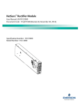
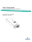
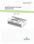
NetSure™ -48 VDC Power System
User Instructions, Section 6032 (Issue M, January 12, 2015)
Specification Number: 582136600
Model Number: 211NGFB
NetSure™ -48 VDC Power System
User Instructions, Section 6032 (Issue M, January 12, 2015)
This page is intentionally blank.
Spec. No: 582136600
Model No: 211NGFB
Section 6032
Issue M, January 12, 2015
NetSure™ -48 VDC Power System
User Instructions, Section 6032 (Issue M, January 12, 2015)
Table of Contents
Admonishments Used In This Document................................................................................................................ ii
Important Safety Instructions .............................................................................................................................. iii
General Safety ........................................................................................................................................................iii
Voltages .................................................................................................................................................................iii
Battery ...................................................................................................................................................................iii
Handling Equipment Containing Static Sensitive Components .................................................................................iii
Static Warning ..................................................................................................................................................... iv
System Overview .................................................................................................................................................. 1
Preface ................................................................................................................................................................... 1
System Description ................................................................................................................................................. 1
Operating Procedures ........................................................................................................................................... 2
Controller and Rectifier ........................................................................................................................................... 2
List KG GMT Load Distribution Fuse Panel ................................................................................................................ 2
Maintenance ......................................................................................................................................................... 2
Important Safety Instructions.................................................................................................................................. 2
System Maintenance Procedures ............................................................................................................................ 2
Troubleshooting and Repair .................................................................................................................................. 3
Contact Information ............................................................................................................................................... 3
Controller and Rectifiers ......................................................................................................................................... 3
Controller Configuration ......................................................................................................................................... 3
System Troubleshooting Information ...................................................................................................................... 3
Replacement Information ....................................................................................................................................... 4
Replacement Procedures ........................................................................................................................................ 4
Spec. No: 582136600
Model No: 211NGFB
i
Section 6032
Issue M, January 12, 2015
NetSure™ -48 VDC Power System
User Instructions, Section 6032 (Issue M, January 12, 2015)
Admonishments Used In This Document
DANGER! Warns of a hazard the reader will be exposed to that will likely result in death or serious injury
if not avoided. (ANSI, OSHA)
Danger
Warning
Caution
WARNING! Warns of a potential hazard the reader may be exposed to that could result in death or
serious injury if not avoided. This admonition is not used for situations that pose a risk only to
equipment, software, data, or service. (ANSI)
CAUTION! Warns of a potential hazard the reader may be exposed to that could result in minor or
moderate injury if not avoided. (ANSI, OSHA) This admonition is not used for situations that pose a risk
only to equipment, data, or service, even if such use appears to be permitted in some of the applicable
standards. (OSHA)
ALERT! Alerts the reader to an action that must be avoided in order to protect equipment, software,
data, or service. (ISO)
Alert
ALERT! Alerts the reader to an action that must be performed in order to prevent equipment damage,
software corruption, data loss, or service interruption. (ISO)
Alert
FIRE SAFETY! Informs the reader of fire safety information, reminders, precautions, or policies, or of the
locations of fire-fighting and fire-safety equipment. (ISO)
Fire Safety
SAFETY! Informs the reader of general safety information, reminders, precautions, or policies not related
to a particular source of hazard or to fire safety. (ISO, ANSI, OSHA)
Safety
Spec. No: 582136600
Model No: 211NGFB
ii
Section 6032
Issue M, January 12, 2015
NetSure™ -48 VDC Power System
User Instructions, Section 6032 (Issue M, January 12, 2015)
Important Safety Instructions
General Safety
Danger
Battery
DANGER!
YOU MUST FOLLOW APPROVED SAFETY PROCEDURES.
Warning
Performing the following procedures may expose you to
hazards. These procedures should be performed by
qualified technicians familiar with the hazards
associated with this type of equipment. These hazards
may include shock, energy, and/or burns. To avoid
these hazards:
a) The tasks should be performed in the order
indicated.
Warning
Warning
b) Remove watches, rings, and other metal objects.
c) Prior to contacting any uninsulated surface or
termination, use a voltmeter to verify that no
voltage or the expected voltage is present.
WARNING! Correct polarity must be observed when
connecting battery leads.
WARNING! Special safety precautions are required for
procedures involving handling, installing, and servicing
batteries. Observe all battery safety precautions in this
manual and in the battery instruction manual. These
precautions should be followed implicitly at all times.
WARNING! A battery can present a risk of electrical
shock and high short circuit current. Servicing of
batteries should be performed or supervised only by
properly trained and qualified personnel knowledgeable
about batteries and the required precautions.
The following precautions should be observed when
working on batteries:
d) Wear eye protection.
e) Use double insulated tools appropriately rated for
the work to be performed.
•
Remove watches, rings, and other metal objects.
•
Eye protection should be worn to prevent injury
from accidental electrical arcs.
•
Use certified and well maintained insulated tools.
Use double insulated tools appropriately rated for
the work to be performed. Ensure that wrenches
with more than one working end have only one end
exposed.
•
Dispose of used batteries according to the
instructions provided with the batteries. Do not
dispose of batteries in a fire. They may explode.
Voltages
AC Input Voltages
Danger
DANGER! This system operates from AC voltage capable
of producing fatal electrical shock. AC input power
must be completely disconnected from the branch
circuits wiring used to provide power to the system
before any AC electrical connections are made. DO NOT
apply AC power to the system until all electrical
connections have been completed and checked.
ALWAYS FOLLOW THE BATTERY MANUFACTURER’S
RECOMMENDATIONS AND SAFETY INSTRUCTIONS.
DC Input/Output Voltages
Danger
DANGER! This system produces DC Power and may
require battery to be connected to it. Although the DC
voltage is not hazardously high, the rectifiers and/or
battery can deliver large amounts of current. Exercise
extreme caution not to inadvertently contact or have
any tool inadvertently contact a battery or output
terminal or exposed wire connected to a battery or
output terminal. NEVER allow a metal object, such as a
tool, to contact more than one termination or battery
terminal at a time, or to simultaneously contact a
termination or battery terminal and a grounded object.
Even a momentary short circuit can cause sparking,
explosion, and injury.
Spec. No: 582136600
Model No: 211NGFB
Caution
CAUTION! Performing maintenance and/or
troubleshooting procedures may interrupt power to the
loads, if battery reserve is not sufficient.
Handling Equipment Containing
Static Sensitive Components
Alert
iii
ALERT! Installation or removal of equipment containing
static sensitive components requires careful handling.
Before handling any equipment containing static
sensitive components, read and follow the instructions
contained on the Static Warning Page.
Section 6032
Issue M, January 12, 2015
NetSure™ -48 VDC Power System
User Instructions, Section 6032 (Issue M, January 12, 2015)
Static Warning
The printed circuit cards used in this equipment contain static sensitive components. The warnings listed below must be observed to
prevent damage to these components. Disregarding any of these warnings may result in personal injury or damage to the equipment.
1.
Strictly adhere to the procedures provided in this document.
2.
Before touching any static sensitive component or printed circuit card containing such a component, discharge all static
electricity from yourself by wearing a wrist strap grounded through a one megohm resistor. Some wrist straps, such as
Emerson Network Power Part Number 631810600, have a built-in one megohm resistor; no external resistor is necessary. Read
and follow wrist strap manufacturer’s instructions outlining use of a specific wrist strap.
3.
Do not touch the traces or components on a printed circuit card containing static sensitive components.
Handle the printed circuit card only by the edges that do not have connector pads.
4.
After removing a printed circuit card containing a static sensitive component, place the printed circuit card only on conductive
or anti-static material such as conductive foam, conductive plastic, or aluminum foil. Do not use ordinary Styrofoam™ or
ordinary plastic.
5.
Store and ship static sensitive devices or printed circuit cards containing such components only in static shielding containers.
6.
If necessary to repair a printed circuit card containing a static sensitive component, wear an appropriately grounded wrist strap,
work on a conductive surface, use a grounded soldering iron, and use grounded test equipment.
Spec. No: 582136600
Model No: 211NGFB
iv
Section 6032
Issue M, January 12, 2015
NetSure™ -48 VDC Power System
User Instructions, Section 6032 (Issue M, January 12, 2015)
System Overview
They are designed with the latest patented switch-mode
technology using DSP (Digital Signal Processing) functionality for
efficient operation. This means that, within the normal operating
ambient temperature range and input voltage range, the
maximum available output power is a constant 500W or 1000W.
Within these ranges, the Rectifier Modules operate in one of three
modes, depending upon load demands. Transition between
modes is completely automatic. If ambient temperature rises
above or input voltage falls below acceptable values, Rectifier
Modules continue to operate but at derated output power levels.
Preface
This document (Section 6032) provides User Instructions for
NetSure™ Power System Model 211NGFB, Spec. No. 582136600.
The complete Customer Documentation Package consists of…
System Installation Manual
•
Power System Installation Instructions: Section 6031
System User Manual
•
Power System User Instructions: Section 6032
•
Rectifier Instructions: UM1R481000
•
Power System “System Application Guide”:
SAG582136600
•
Engineering Drawings
a.
Constant Voltage Mode: For any initial output voltage
setting from 48 to 58 volts, output voltage remains
constant regardless of load. This is the normal operating
condition, in which loads are being supplied and batteries
are float charged. Rectifier Modules operate in the
Constant Voltage Mode unless load increases to the point
where the product of load current and output voltage is
approximately 500W or 1000W.
b.
Constant Power Mode: As load increases above
approximately 500W or 1000W (non-adjustable), output
current continues to increase, but output voltage
decreases as required to maintain constant output
power. Rectifier Modules operate in the Constant Power
Mode unless load continues to increase to the point
where the current limit setting is reached.
c.
Constant Current Mode: If load increases above the
current limit setting, output voltage decreases linearly to
maintain output current at current limit.
Controller User Manual
•
NCU Controller User Instructions: UM1M830BNA
•
ACU+ Controller User Instructions: UM1M820BNA
•
SCU+ Controller User Instructions: UM1M521BNA
For factory settings of all configurable Controller parameters, refer
to the Configuration Drawing (C-drawing) supplied with your
Power System.
System Description
Controller
The NetSure™ 211NGFB DC Power System is a complete integrated
power system containing rectifiers, intelligent control, metering,
monitoring, and distribution. This power system consists of the
following mounted in a 1RU or 2RU high by 19” or 23” wide shelf.
The controller controls the operation of the rectifier modules. The
controller also provides power system control, metering,
monitoring, and alarm functions.
NCU (NetSure Control Unit): The controller provides power system
control (including optional low voltage battery disconnect (LVBD)
and low voltage load disconnect (LVLD) control), rectifier control
(including a charge control function), metering functions,
monitoring functions, local/remote alarm functions, and
connections for binary inputs and programmable relay outputs.
The controller also supports rectifier temperature compensation if
the system is equipped with a temperature probe(s). Temperature
probe(s) may also be designated to monitor ambient temperature
and/or battery temperature. The controller also provides data
acquisition, system alarm management, and advanced battery and
energy management. The controller contains a color TFT display
and keypad for local access. The controller provides an Ethernet
port and comes with comprehensive webpages for remote access.
The controller has SNMP V3 capability for remote system
management. The controller supports software upgrade via its
500W or 1000W Rectifier Modules
•
The 1RU high by 19” wide shelf accommodates two (2)
500W or 1000W Rectifier Modules.
•
The 1RU high by 23” wide shelf accommodates three (3)
500W or 1000W Rectifier Modules.
•
The 2RU high by 19” wide shelf accommodates four (4)
500W or 1000W Rectifier Modules.
•
The 2RU high by 23” wide shelf accommodates six (6)
500W or 1000W Rectifier Modules.
The Rectifier Modules provide load power, battery float current,
and battery recharge current during normal operating conditions.
The Rectifier Modules are designed to provide constant power.
Spec. No: 582136600
Model No: 211NGFB
1
Section 6032
Issue M, January 12, 2015
NetSure™ -48 VDC Power System
User Instructions, Section 6032 (Issue M, January 12, 2015)
USB port. Refer to the NCU Controller Instructions
(UM1M830BNA) for more information.
Distribution Unit
ACU+ (Advanced Control Unit Plus): The controller provides power
system control (including optional low voltage battery disconnect
(LVBD) and low voltage load disconnect (LVLD) control), rectifier
control (including a charge control function), metering functions,
monitoring functions, and local/remote alarm functions. The
controller also supports rectifier temperature compensation if the
system is equipped with a temperature probe(s). Temperature
probe(s) may also be designated to monitor ambient temperature
and/or battery temperature. The controller also provides data
acquisition, system alarm management, and advanced battery and
energy management. The controller contains an LCD display and
keypad for local access. The controller provides an Ethernet port
and comes with comprehensive webpages for remote access. The
controller has SNMP capability for remote system management.
The controller supports software upgrade via its USB port. Refer to
the ACU+ Controller Instructions (UM1M820BNA) for more
information.
SCU+ (Standard Control Unit Plus): The SCU+ provides Rectifier
Module and optional Low Voltage Battery Disconnect (LVBD) or
Low Voltage Load Disconnect (LVLD) control, metering functions,
monitoring functions, and local/remote alarms. The SCU+
contains an LCD display and keypad for local access. It provides
connection for binary inputs, programmable relay outputs, and a
charge control function. The controller also supports rectifier
temperature compensation if the system is equipped with a
temperature probe (or multiple temperature probes connected via
a Temperature Concentrator (SM TEMP), and ambient
temperature monitoring if equipped with a second temperature
probe. The SCU+ also provides Ethernet connection and SNMP
capability.
Various Distribution Unit options are available, as described in
SAG582136600. The Distribution Unit can be equipped with an
optional Low Voltage Battery Disconnect (LVBD) or Low Voltage
Load Disconnect (LVLD) contactor.
Operating Procedures
Controller and Rectifier
For operation instructions on these units, refer to the following
documents.
•
NCU Controller Instructions (UM1M830BNA)
•
ACU+ Controller Instructions (UM1M820BNA)
•
SCU+ Controller Instructions (UM1M521BNA)
•
Rectifier Instructions (UM1R481000)
List KG GMT Load Distribution Fuse Panel
Local Controls and Indicators
Refer to Figure 1 for indicator locations.
PWR A and PWR B indicator: When illuminated (green), indicate
power is supplied to the A and B sides, respectively.
Note: The split (A/B) input bus option provided on this panel is
strapped for a single input in this Power System.
FUSE ALARM indicator: When illuminated (red), indicates a load
distribution fuse is open. The open fuse provides a mechanical
indicator visible through the fuse safety cover.
Figure 1. Indicator Locations (List KG)
PWR
A
FUSE
ALARM
PWR
B
Maintenance
System Maintenance Procedures
Important Safety Instructions
The maintenance procedures listed in Table 1 should be performed
and recorded at the recommended interval to ensure continual
system operation.
Danger
DANGER! Adhere to the “Important Safety Instructions”
presented at the front of this document.
Spec. No: 582136600
Model No: 211NGFB
2
Section 6032
Issue M, January 12, 2015
NetSure™ -48 VDC Power System
User Instructions, Section 6032 (Issue M, January 12, 2015)
The table references specific sections in the User Instructions
(Section 6032) or the separate Installation Instructions (Section
6031) that help in performing these procedures.
Table 1.
Troubleshooting Alarm Conditions on the Controller
The controller displays alarm conditions as listed in the Available
Alarms section of the separate Controller User Manual.
Programmable external alarm relays are also available. The
separate Power System Installation Manual (Section 6031) lists the
factory default alarm relay configurations. Your system may have
different configurations then those listed. Refer to the
Configuration Drawing (C-drawing) supplied with your Power
System for your alarm relay configurations.
Maintenance Procedures to be Performed at 6-Month
Intervals
PROCEDURE
REFERENCED IN
Check ventilation
openings for obstructions
such as dust, papers,
manuals, etc.
--
Inspect and tighten all
installer's connections.
The controller’s Active Alarm and Alarm History submenus allows
the user to view alarm details. Refer to the separate Controller
User Manual to access these menus.
Section 6031,
Making Electrical
Connections section.
Checking the NCU or ACU+ Controller’s Current Limit Point
after Adding or Removing a Rectifier
Troubleshooting and Repair
If a rectifier is added to the power system, the system current limit
point will automatically increase by the percentage each existing
rectifier was set to provide prior to the addition.
Contact Information
Support contact information is provided at the back of this
document.
Controller and Rectifiers
For troubleshooting and repair instructions on these units, refer to
the following documents.
•
NCU Controller Instructions (UM1M830BNA)
•
ACU+ Controller Instructions (UM1M820BNA)
•
SCU+ Controller Instructions (UM1M521BNA)
•
Rectifier Instructions (UM1R481000)
It is recommended that the current limit point be checked
whenever a rectifier is added to or removed from the power
system.
Controller Configuration
For factory settings of all configurable controller parameters, refer
to the Configuration Drawing (C-drawing) supplied with your
Power System.
System Troubleshooting Information
General
This system is designed for ease in troubleshooting and repair. The
various indicators, as described in the "Operating Procedures"
section and the separate Controller and Rectifier User Manuals, are
designed to isolate failure to a specific element. Once the faulty
element has been identified, refer to the next sections,
“REPLACEMENT INFORMATION” and "REPLACEMENT
PROCEDURES".
Spec. No: 582136600
Model No: 211NGFB
If a rectifier is removed from the system (and the Rect Comm Fail
alarm is reset), the current limit point will remain unchanged
unless the capacity of the remaining rectifiers is not sufficient to
maintain the present current limit point. If that happens, the
current limit point will automatically increase to the maximum
(121% of the remaining rectifiers).
3
When setting total rectifier current limit, the set point to each unit
is the total set point divided by the number of units. For example,
if the system contains five rectifiers and the current limit is set to
150 amps then each rectifier has a current limit set point of 30
amps. If one or more rectifiers are removed or fail it will take
several seconds for the individual set points to the remaining
rectifiers to be reset. In the example given, if one rectifier is
removed the current limit set point will drop to 120 amps (30
amps times four remaining rectifiers) until the controller can send
updated set points to the remaining rectifiers. This takes a couple
communication cycles (several seconds) after which each rectifier
would have a new set point of 37.5 amps for a total of 150 amps.
The total current limit of the rectifiers should not be set such that
the loss of the redundant rectifiers will cause this temporary set
point to drop below the actual maximum expected load. If
batteries are used on the rectifier output, the batteries should
support the load until the current limit set points can be reestablished due to loss of a rectifier.
Section 6032
Issue M, January 12, 2015
NetSure™ -48 VDC Power System
User Instructions, Section 6032 (Issue M, January 12, 2015)
Refer to the ACU+ Instructions (UM1M820BNA) or NCU
Instructions (UM1M830BNA) for a procedure.
Replacement Procedures
Important Safety Instructions
Clearing a Rectifier Communications Fail Alarm after Removing
a Rectifier
Danger
If a rectifier module is removed from the system, a rectifier
communications failure alarm is generated. If the rectifier module
will not be replaced, the alarm should be cleared.
Refer to the controller instructions for a procedure.
Clearing a Rectifier Lost Alarm
If the controller resets while a rectifier communications fail alarm is
active, the rectifier communications fail alarm is replaced with a
rectifier lost alarm. The alarm should be cleared.
Refer to the controller instructions for a procedure.
Replacement Information
Replacement Assemblies
When a trouble symptom is localized to a faulty Rectifier Module
or Controller, that particular device should be replaced in its
entirety. Other than a Rectifier Module fan replacement, no
attempt should be made to troubleshoot or repair individual
components on any Rectifier Module or Controller. Refer to the
separate Controller or Rectifier Module User Manuals for
replacement procedures.
DANGER! Adhere to the “Important Safety Instructions”
presented at the front of this document.
Replacing a Rectifier Module
Refer to the separate Rectifier Module User Manual for a rectifier
replacement procedure. Before replacing any Rectifier Modules,
note the following.
In a Power System equipped with an NCU or ACU+ controller, the
rectifier module being replaced is assigned by the controller the
lowest available identification number. If desired, you can change
the identification number. Refer to the ACU+ Instructions
(UM1M820BNA) or NCU Instructions (UM1M830BNA) for a
procedure.
Replacing the Controller
Refer to the controller instructions for a procedure.
Refer to SAG582136600 for replacement part numbers.
Spec. No: 582136600
Model No: 211NGFB
4
Section 6032
Issue M, January 12, 2015
NetSure™ -48 VDC Power System
User Instructions, Section 6032 (Issue M, January 12, 2015)
Replacing a GMT Distribution Fuse (List 1 and 2 Shelves)
If a GMT distribution fuse opens; replace with the same type and rating, or equivalent. Refer to SAG582136600 for fuse replacement part
numbers.
Refer to Figure 2 as this procedure is performed.
Procedure
1.
Adhere to the “Important Safety Instructions” presented at the front of this document. This procedure exposes the Distribution
Unit. BATTERY VOLTAGE is present on the Distribution Unit.
2.
Performing this procedure may activate external alarms. Do one of the following. If possible, disable these alarms. If these
alarms cannot be easily disabled, notify the appropriate personnel to disregard any future alarms associated with this system.
3.
Loosen the captive fastener located on the front of the Distribution Unit.
4.
Partially slide the Distribution Unit out of the Power/Distribution Shelf.
5.
Replace the open GMT fuse. Ensure a safety cover is installed over the new fuse.
6.
Carefully slide the Distribution Unit back into the Power/Distribution Shelf.
7.
Secure the Distribution Unit by tightening the front captive fastener.
8.
Enable the external alarms, or notify appropriate personnel that this procedure is finished.
9.
Ensure that there are no local or remote alarms active on the system.
Figure 2. GMT Distribution Fuse Replacement (List 1 and 2, List 1 shown)
Front
GMT Fuses
and Safety Covers
Spec. No: 582136600
Model No: 211NGFB
5
Section 6032
Issue M, January 12, 2015
NetSure™ -48 VDC Power System
User Instructions, Section 6032 (Issue M, January 12, 2015)
Replacing a GMT Distribution Fuse (List 5 and 6 Shelves)
If a GMT distribution fuse opens, replace with the same type and rating, or equivalent. Refer to SAG582136600 for fuse replacement part
numbers.
Refer to Figure 3 as this procedure is performed.
Procedure
1.
Adhere to the “Important Safety Instructions” presented at the front of this document. This procedure exposes the Distribution
Unit. BATTERY VOLTAGE is present on the Distribution Unit.
2.
Performing this procedure may activate external alarms. Do one of the following. If possible, disable these alarms. If these
alarms cannot be easily disabled, notify the appropriate personnel to disregard any future alarms associated with this system.
3.
Open the Distribution’s Unit front access panel.
4.
Replace the open GMT fuse. Ensure a safety cover is installed over the new fuse.
5.
Close the Distribution’s Unit front access panel.
6.
Enable the external alarms, or notify appropriate personnel that this procedure is finished.
7.
Ensure that there are no local or remote alarms active on the system.
Figure 3. GMT Distribution Fuse Replacement (List 5 and 6, List 5 shown)
Front
GMT Fuses
and Safety Covers
Front
GMT Fuses
and Safety Covers
(Max. 15A)
Spec. No: 582136600
Model No: 211NGFB
GMT Fuses
and Safety Covers
(Max. 10A)
6
Section 6032
Issue M, January 12, 2015
NetSure™ -48 VDC Power System
User Instructions, Section 6032 (Issue M, January 12, 2015)
Replacing a GMT Distribution Fuse (List KG GMT Fuse Load
Distribution Panel)
Distribution Unit Replacement
If the Distribution Unit should need to be replaced, replace the
complete Power/Distribution Shelf.
Load distribution fuses are located on the front panel of List KG. If
replacement of a distribution fuse becomes necessary, replace
only with Bussmann GMT type of the correct rating. Ensure a
safety cover is installed on the replacement fuse, as shown in
Figure 4.
Figure 4. Safety Fuse Cover, Part No. 102774 (Bussmann GMT-Y)
Spec. No: 582136600
Model No: 211NGFB
7
Section 6032
Issue M, January 12, 2015
NetSure™ -48 VDC Power System
User Instructions, Section 6032 (Issue M, January 12, 2015)
This page is intentionally blank.
Spec. No: 582136600
Model No: 211NGFB
8
Section 6032
Issue M, January 12, 2015
NetSure™ -48 VDC Power System
User Instructions, Section 6032 (Issue M, January 12, 2015)
NetPerform™ Optimization Services
At Emerson Network Power, we understand the importance of reliable equipment – it’s critical to both your business and your bottom
line. That is why we offer a wide array of services to meet all of your network infrastructure needs.
Customer Service (Pre-Shipment)
Email
[email protected]
Phone
1.800.800.1280 option 1
Pricing and availability [1,2], purchase orders, expediting requests
and order tracking. Ask for your company’s dedicated Customer Service
Associate.
Customer Support Center (Post-Shipment)
Email
[email protected]
Phone
1.956.661.6867
After an order has shipped, contact our Customer Support Center
with related questions, concerns or claims.
Account Management
Email
[email protected]
Phone
1.800.800.1280 option 2
Provides quotes and bid responses for custom configured [2] DC power
systems and outside plant enclosures for customers and channel partners
(Reps, VARs & Distributors).
Spare Parts
Email
[email protected]
[email protected]
Phone
1.800.800.1280 option 5
Pricing and purchase orders for spare parts, including but not limited to
breakers, cables, fuses, rectifier fans, misc. breaker and fuse panels,
enclosure fans, doors and switches, etc.
DC Power Depot Repair
Email
[email protected]
Phone
1.800.800.1280 option 6
Creates and processes RMAs for depot repair and refurbishment.
Determines repair and refurbishment lead times and pricing based on
warranties/contractual agreements. Provides repair shipping information
and status.
Technical Support
Email
[email protected]
[email protected]
Phone
1.800.800.5260
Email
[email protected]
Phone
1.440.240.0639
[1]
[2]
Answers technical product and system questions; determines status of
warranties and contractual agreements for repair.
Provide quotes and bid responses for application specific configured DC
power systems for Liebert DC power sales reps.
Contact Account Management for custom-configurations.
Contact Spare Parts for parts and accessories.
Spec. No: 582136600
Model No: 211NGFB
9
Section 6032
Issue M, January 12, 2015
NetSure™ -48 VDC Power System
User Instructions, Section 6032 (Issue M, January 12, 2015)
The information contained in this document is subject to change without notice and may
not be suitable for all applications. While every precaution has been taken to ensure the
accuracy and completeness of this document, Emerson Network Power, Energy Systems,
North America, Inc. assumes no responsibility and disclaims all liability for damages resulting from use of this information or for any errors or omissions. Refer to other local
practices or building codes as applicable for the correct methods, tools, and materials to
be used in performing procedures not specifically described in this document.
The products covered by this instruction manual are manufactured and/or sold by Emerson
Network Power, Energy Systems, North America, Inc. This document is the property of
Emerson Network Power, Energy Systems, North America, Inc. and contains confidential and
proprietary information owned by Emerson Network Power, Energy Systems, North
America, Inc. Any copying, use or disclosure of it without the written permission of Emerson
Network Power, Energy Systems, North America, Inc. is strictly prohibited.
Names of companies and products are trademarks or registered trademarks of the
respective companies. Any questions regarding usage of trademark names should be
directed to the original manufacturer.
EmersonNetworkPower.com/Energy Systems (North America )
EmersonNetworkPower.eu/EnergySystems (EMEA)
© Emerson Network Power, Energy Systems, North America, Inc. 2015.
Business-C ritical Continui ty ™, Emerson Network Powe r™, the Emerson Netw ork Power logo , Emer son™ and Conside r it Solved are serv ice marks and
trademar ks of Emer son Electric Co. EnergyMaster ™, eSure™, NetPer form™, NetR each ™, NetSpan™, NetSure™ and NetXtend ™ are tradema rks of Eme rson
Network Power, Energy Syste ms, Nor th America, Inc . Any other product, brand, or company names or logos are the property of the respective owner.
Spec. No: 582136600
Model No: 211NGFB
While every precaution has been taken to ensure accuracy and
completeness herein, Emerson Electric Co. assumes no responsibility,
and disclaims all liability, for damages resulting from use of this
information or for any errors or omissions. Specifications subject to
change without notice.
Section 6032
Issue M, January 12, 2015