1
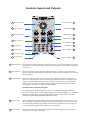
mod
VCO User Guide
Vintage discrete transistor core VCO
Thank you for purchasing the AJH Synth MiniMod VCO module, which like all AJH Synth Modules,
has been designed and handbuilt in the UK from the very highest quality components. We hope
that it will help and inspire you towards creating some great music and soundscapes!
The discrete all transistor core of this Voltage Controlled Oscillator is an exact emulation of the
original, and now very rare, R A Moog Model D Oscillator from 45 years ago. It features a fully
matched PNP transistor expo. converter and P-FET transistor buffer amplifier section but with the
advantage of much improved temperature stability and modern construction using reliable
precision SMT components along with Eurorack modular synthesiser expandibility.
It features front panel switchable octave selection and four independent waveform outputs
including the famous “Sharktooth” waveform, Sawtooth wave, Square wave and Triangle wave
and when used as part of a full MiniMod system can provide a very accurate emulation of the
Model D systhesiser and it’s highly acclaimed “fat vintage” analogue sound.
The Square wave output has fully adjustable Pulse Width Modulation, with manual and CV control
rather than the more restricting selection of square wave or two static fixed pulse widths of the
original design.
Also included are Exponential and Linear modulation inputs and two different types of oscillator
sync which help to make this a very versatile Eurorack VCO in its own right.
Module width is 14 HP of EuroRack space and it is compatible with standard Euro Rack cases. The
height of the panel is 128.5mm, and depth is 38mm. There are four mounting holes at the corners
of the module and we provide 4 of M3 rack fixing screws, along with a Eurorack compatible
power cable. Current consumption is 55mA from the +12V supply rail and 40mA from the -12V
supply rail.
All AJHSynth modules are covered by a one year guarantee against manufacturing defects.
Notes:
As with all vintage analogue oscillators, after powering up it is best to be allowed to “warm up” for 15
minutes or so before use. Tuning immediately after power up is not advised as it takes time for the
internal circuitry to get up to temperature and stabilise. After the warm up period it will maintain pitch
well - much better than the original on which it is based!
It is very important that the power supply ribbon cable is connected correctly, see the “adjustment and
calibration” section for an illustration of the correct orientation.
www.ajhsynth.com
Controls, Inputs and Outputs
1 Octave Switch
5 Exp. CV Level
Linear CV Level 7
Tune Control 2
9 Sync Threshold
PWM Control 16
PWM Shape
15
4 Exp. CV Input
Shark Output 13
10 Sync Type
Saw Output 11
8 Sync Input
Square Output 14
3 1 V / Oct. Input
6 Linear Input
Triangle Output 12
1 Octave Switch : Use the Octave switch to quickly select preset octaves, the Lo setting reduces the oscillator frequency into the Low Frequency Oscillator range so that it can be used as a modulation source.
2 Tune Control :
The tune control varies the oscillator pitch by around +/- 8 notes. Larger variations in
pitch can be obtained by applying a positive or negative control voltage to the 1 Volt per
Octave input (3)
3 1 V/Oct. Input : This is the 1 Volt per Octave control voltage input. Applying a positive voltage to this
input raises oscillator pitch at the rate of exactly one octave for each volt applied, and a
negative voltage will reduce the pitch by exactly one octave per volt. The acceptable
input range is +/- 7 Volts. A limitation of the vintage oscillator core design means that
tracking may not follow the 1V/Oct law above 10KHz
Distribution Buss 1V/Octave CV signal:
The Eurorack power distribution buss can transmit a 1V/Octave voltage from a Mini/CV
converter or similar source. The MiniMod VCO accepts this signal by default as it is “normalled”
through the 1V/Oct socket, however plugging a jack into the 1V/Oct socket unswitches /
defeats this control voltage and allows the VCO to run free.
4 Exp CV Input :
This is the Exponential Control Voltage input. Acceptable input voltage range is +/- 5V.
When a voltage is applied to this input it varies the oscillator pitch in a similar fashion to
the 1 V/Oct input, however the amount of control voltage applied to the oscillator core
can be regulated using the Exponential CV Level control (5).
5 Exp. CV Level :
This control adjusts the amount of voltage from the Exp. CV input that is passed to the
oscillator core, its range is 0 to 120%.
6 Linear Input :
This is the Linear Control Voltage Input. Acceptable input voltage range is +/- 5V. This is a
more subtle modulation effect which varies the oscillator pitch by up to +/- 7 notes
depending upon the setting of the Linear CV Level Control (7)
7 Linear CV Level :
Controls the amount of Linear Modulation applied to the oscillator core from the Linear
CV Input (6)
8 Sync Input :
A rising ramp waveform of +/- 5V (e.g. the Saw waveform from another MiniMod VCO) can
be applied to this input to prematurely reset (synchronise) the oscillator waveform for
interesting sonic results. The sync effect is very level sensitive and is set using the Sync
Threshold control (9).
If it is desired to use a falling ramp waveform from a different oscillator for sync it will
need to be fed through an invertor to convert it to the rising ramp waveform required for
effective triggering.
9 Sync Threshold :
The Sync effect is very level sensitive and the waveform level from the Sync Input (8)
presented to the oscillator core can be set using this control. Start with the control fully
counter clockwise and gradually increase it until the desired effect is obtained. The
frequency relationship between this oscillator and the synchronising oscillator plays a
large part in the resulting sounds created.
If using another MiniMod VCO as the sync source, then Sync Threshold knob position 2 to
3 is a good starting point when the Sync Type switch is in the “down” position, and control
knob position 7 to 8 when this switch is in the “up” position. Experiment!
10
Sync Type :
This switches between the two different sync types. With the switch “down” regular sync is
effective, which can be used to create ripping “laser harp” type sounds. When the switch is
set to "up", a rising ramp waveform is required as the sync source, and this should be set
to a higher frequency than the slave oscillator. Different Sync threshold levels are
required for the “up” and “down” Sync switch positions.
11
Saw Output :
Rising ramp waveform output. It has a level of +/-5 volts centred around 0v. The output
impedance is 1Kohm.
12
Triangle Output : Triangle wave output. It has a level of +/-5 volts centred around 0v. The output impedance
is 1Kohm.
13
Shark Output :
14
Square Output : Square wave output. It has a level of +/-5 volts centred around 0v. The duty cycle
(amount of time the waveform is “high” against “low”) can be varied with the Manual
PWM control (15) or under voltage control (16). The output impedance is 1Kohm.
15
PWM Shape :
Adjusts the duty cycle of the square wave between approximately 10% and 90%. When
set to the half way (12 o’clock) position the duty cycle is 50%, which creates a regular
square wave.
16
PWM Control :
A control voltage can be applied to the PWM CV Input to vary the PWM duty cycle. The
control voltage range should be between +/- 5volts and the intensity can be controlled
between 0% to 100% with the PWM CV rotary control knob. A low frequency triangle
wave to the PWM CV Input will give the classic sweeping PWM effect. The PWM Shape
Control is still effective when using PWM CV and it changes the offset level.
The famous “Sharktooth” waveform from the early Model D synthesiser. It has an output
level of +/-5 volts centred around 0v. The output impedance is 1Kohm.
Adjustment and Calibration
Note:
This information is given for completeness, the MiniMod VCO is calibrated after manufacture
and under normal circumstances should not require any user adjustment.
C Octave Adjust
A Tune Adjust
HFT Adjust
D
Scale Adjust
B
Shape Adjust
E
Power Cable
Red Stripe aligns with -12V as shown
A Tune Adjust :
Sets the default frequency for the VCO. This is a multi-turn trimmer that should be
adjusted with a fine jeweller’s screwdriver. Turn counter clockwise to increase VCO pitch
and clockwise to reduce the pitch. Adjusting this trimmer will not affect the scaling.
B Scale Adjust :
FOR MANUFACTURER ADJUSTMENT ONLY. Sets the V/Oct scaling for the VCO. Specialist
test equipment is needed to calibrate this trimmer correctly.
C Octave Adjust :
FOR MANUFACTURER ADJUSTMENT ONLY. Sets the span for the Octave Select Switch.
Specialist test equipment is needed to calibrate this trimmer correctly.
D HFT Adjust :
FOR MANUFACTURER ADJUSTMENT ONLY. Specialist test equipment is needed to
calibrate this trimmer correctly.
E Shape Adjust :
FOR MANUFACTURER ADJUSTMENT ONLY. This sets the current level through the
P-FET transistor buffer and incorrect adjustment can halt the Oscillator completely, so
NO ATTEMPT should be made to adjust this trimmer.
If you need any help using this module or have any technical questions please feel free to
contact us at [email protected]
Copyright © AJHSynth 2014